1
Operation Manual
OM 1169-1
Group: WSHP
Document No: 910149319
Date: November 2013
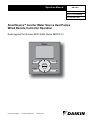
SmartSource™ Inverter Water Source Heat Pumps
Wired Remote Controller Operation
Daikin Applied Part Number #910126993 (Daikin #BRC1E71)
Mode
On/Off
Menu
OK
Fan
Speed
©2013 Daikin Applied • www.DaikinApplied.com • 800.432.1342
Cancel
Contents
Introduction...........................................................................3
Proper Use For Effective Energy Savings.........................3
Preparation........................................................................3
Safety Considerations.......................................................3
Meanings of WARNING and CAUTION Symbols:.............3
Remote Controller Installation............................................4
Dimensions & Mounting Methods......................................4
Mounting the Remote Controller........................................5
Wiring The Remote Controller...........................................6
Button Locations & Descriptions........................................7
Controller Button Descriptions...........................................7
Display Icons – Names & Functions...................................7
How To Follow This Manual...............................................8
Main Menu Screen Overview...............................................9
Moving Within The Main Menu Screen..............................9
Setup Guide..........................................................................9
Setting The Language.......................................................9
Daylight Savings Time.......................................................9
Setting The 12H/24H Clock.............................................10
Setting The Date & Time..................................................10
Standard and Detailed Display Modes............................ 11
Displaying Temperature In Fahrenheit or Celsius............12
Entering Maintenance Contact Information.....................12
Confirmation Registered Details......................................13
Field Settings...................................................................13
Mode & Code Settings.....................................................15
Specific Field Settings Changes......................................16
Setting The Fan Mode ....................................................16
Enabling Setback Temperature Control...........................17
Activating Filter Change Indicator....................................17
Limiting Setpoint Ranges.................................................17
Setting The Setback On/Off Differential...........................18
Setting The Minimum Differential Between Cooling and
Heating Setpoints............................................................18
Prohibiting Remote Controller Keys................................19
Page 2 of 36 / OM 1169-1
Basic Operation..................................................................19
LCD (With Backlight).......................................................19
On/Off Button...................................................................19
Setback Feature..............................................................19
Cool/Heat/Auto Modes....................................................20
Characteristics Of Heat Mode.........................................20
Dry Mode.........................................................................21
Key Lock..........................................................................22
Main Menu...........................................................................23
Main Menu Structure.......................................................23
Quick Reference..............................................................24
Schedule..........................................................................24
Daily Patterns..................................................................24
Settings............................................................................25
Enabling or Disabling The Schedule................................27
Off Timer..........................................................................27
Additional Main Menu Information...................................28
Contrast Adjustment........................................................28
Display Mode...................................................................29
Display Item.....................................................................29
Current Settings...............................................................30
Maintenance....................................................................30
Service Settings Menu.......................................................31
Additional Service Settings Menu Information.................32
Error History.....................................................................32
Indoor Unit Status............................................................32
Forced Fan On................................................................33
General Maintenance.........................................................34
Maintaining The Unit And LCD Display............................34
Reference Information.....................................................34
After-Sale Service...............................................................34
Advise Your Daikin Dealer Of The Following Items.........34
Repairs After Warranty Period.........................................34
Inquiry About After-Sale Service......................................34
Introduction
Proper Use For Effective Energy Savings
Thank you for purchasing the wired remote controller.
This manual describes safety consideration which should be
observed during the use of the product.
Read this manual carefully and be sure you understand the
information provided before attempting to use the product.
Keep this manual where it is readily accessible after reading it
through. If another user operates the product in the future, be
sure to hand over this manual to the new user.
Preparation
Note: For mechanical protection purposes, apply power to
the system units at least six hours before starting the
operation of the system.
WARNING
Do not modify or repair the remote controller. Consult your
Daikin dealer for any modification or for repairs.
Do not relocate or reinstall the remote controller by yourself. Improper installation may result in electric shocks or fire.
Consult your Daikin dealer to relocate or for any reinstallation.
Do not use flammable materials (e.g., hairspray or insecticide) near the remote controller. Do not clean the product
with organic solvents such as paint thinner. The use of organic
solvents may cause cracking, damaging the product, causing
electric shocks, or fire.
Consult the dealer if the remote controller was submerged
under water due to a natural disaster, such as a flood or
hurricane. Do not operate the remote controller at this time
or a malfunction, electric shock, or fire can occur.
The dry mode may not be selected if the remote controller is
master controlled and the system is not already in the cooling
mode of operation. (See page 21 for details)
Safety Considerations
Read these SAFETY CONSIDERATIONS carefully before
operating the remote controller.
Train the customer to operate and maintain the unit.
Inform customers that they should store this Operations
Manual with the Installation Manual for future reference.
Meanings of WARNING and CAUTION
Symbols:
! WARNING
Indicates a potentially hazardous situation which, if not
avoided, could result in death or serious injury.
! CAUTION
Indicates a potentially hazardous situation which, if not
avoided, may result in minor or moderate injury.
It may also be used to alert against unsafe practices.
CAUTION
Do not allow children to play with the remote controller to
avoid causing damage to the product.
Never disassemble the remote controller. Touching the interior parts may result in electric shocks or fire. Consult your
Daikin dealer for internal inspections and adjustments.
Do not touch the remote controller buttons with wet
fingers. Touching the buttons with wet fingers can cause an
electric shock.
Do not wash the remote controller. Doing so may cause electric leakage and result in electric shocks or fire.
Never let the remote controller to get wet. Water can cause
damage to the remote controller, and may cause an electric
shock or fire.
Page 3 of 36 / OM 1169-1
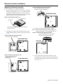
Remote Controller Installation
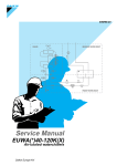
Dimensions & Mounting Methods
Figure 1: Remote controller case dimensions for mounting
Lower case
Back
1-9/16
4-3/4
Operation
lamp
(Green)
4-3/4
Cord outlet hole
1-1/8
3/4
3/16 × 9/16 Oblong hole
7/8
3/16 × 1/4 Oblong hole
3-5/16
1-5/8
Upper case
Front
1-15/16
1-13/16
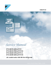
Figure 2: Remote controller mounting methods
Exposed Cord
Embedded Cord
Upper Center
Outlet
3/4
Interior - Back
1-9/16
Upper Outlet
Staple (See Note 1)
(See Note 2)
Through Hole
(ɸ5/16 ~ ɸ3/8)
1-15/16
Left Outlet
Lower Case Portion
3/4
Embedded Cord
(Use Junction Box)
Embedded Cord
(Use Junction Box)
Lower Case Portion
Interior - Back
3-5/16
3-5/16
Lower Case Portion
Interior - Back
1-1/8
Conduit
Junction Box
(Field Supplied)
1-13/16
Junction Box for One Switch
Ex; KJB111A (Optional Accessory)
3/4
Junction Box for Two Switch
Ex; KJB211A (Optional Accessory)
0~3/16
(Between Remote
Controller & Junction Box)
Notes: 1.Remote controller cord and staple are not included, but are field-supplied parts.
2.If the hole size is too large or the location is not correct, the hole may not be hidden by the remote control case.
Table 1: Cable specifications
Type
Vinyl cord with sheath or cable {insulated thickness: 3/8 in. (1mm) or more}
Size
AWG 18 or AWG 16
Total Length
330 ft. (100M)
Page 4 of 36 / OM 1169-1
Remote Controller Installation
Mounting the Remote Controller
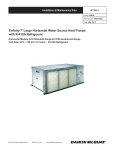
Remove the upper case by doing the following:
1. Insert a screwdriver in the recess of lower case to remove
the upper case (2 points), see Figure 3. Remote controller
PC-board is installed on the upper case. Take care not to
damage the PC-board with the screwdriver. Take care that
dust or moisture does not touch the PC-board.
Figure 6: Cable entry through the top-left
Using an appropriate tool, cut the hatched
area and remove any remaining burrs
Back Interior View
Figure 3: Removing the upper case
Upper case
Screwdriver
Insert and twist the screwdriver
lightly for removal.
Lower case
2. Determine the location where the cabling will enter the
remote controller (back, left side, top left, top center), see
Figure 4.
Figure 4: Cable entry through the back
3. Determine where to install the remote controller.
Note Remote control wiring 2-conductor, stranded, nonshielded copper/PVC or vinyl jacket AWG18 or 16
Figure 7: Cable entry through the top-center
Using an appropriate tool, cut the hatched
area and remove any remaining burrs
Cut-off resin area (hatched area)
Back Interior View
Back View
Figure 5: Cable entry through left side
Using an appropriate tool, cut the
hatched area and remove any
remaining burrs
Back Interior View
4. If the control cable for the remote controller is to be
routed from the rear, make a hole in the wall taking into
consideration the location of the access hole in the lower
case. See Figure 8.
Page 5 of 36 / OM 1169-1
Remote Controller Installation
Figure 8: Through the wall hole location details
External view of the remote controller
5/16 to 3/8
1-9/16
Lower case
Through hole
Align the center of the wall
hole with the center of the
access hole on the controller
lower case when planning the
installation.
1-15/16
Access hole
5/16 to 3/8
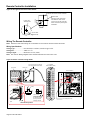
Wiring The Remote Controller
Note: Switch box and control wiring are not included. Do not touch the remote controller PC-board.
Wiring Specifications:
Wiring Type:........................ Non-shielded, 2-conductor, stranded copper cable.
Wiring Size:......................... AWG 18 or 16
Wiring Length:.................... Maximum 330 feet (100m)
Note: See also the “Wiring Diagram Label” located inside the unit’s control box cover.
Figure 9: Remote controller wiring details
Connects to P1 & P2 at the unit
low voltage terminal block X2M
Upper case
Low Voltage
Terminal Block (X2M)
Lower case
BLU
WHT
PNK
GRY SKY BLU
PPL
YLW
Page 6 of 36 / OM 1169-1
BLK
Cable attachment guideline
YLW
Cable attachment
point
ORG
-
RED
Cross-section
Secure the cable at
the attachment point
by using furnished
clamping material.
BRN
Clamp
F1 F2 F1 F2 P1 P2 T1 T2 9 10 11 12
Clamp
PUMP
TRANSMISSION TO OUT/D REMOTE FORCED PUMP
UNIT
CNTRL
OFF INTERLOCK REQUEST
WIRING
PC-board
Unit Control Box
Low voltage wire entry
Button Locations & Descriptions
Functions other than basic operation items (i.e., On/Off,
Operation mode selector, Fan speed control, and temperature
setpoint) are set from the menu screen.
Notes: 1.Do not install the remote controller in places
exposed to direct sunlight, otherwise the LCD will be damaged.
2.Do not pull or twist the remote controller cord, otherwise the remote controller may be damaged.
3.Do not use objects with sharp ends to press the buttons on the remote controller otherwise dam
age may result.
1. Op er at i o n m o d e
selector button
11. L CD (w i t h b ac k l i g h t )
4. Up b u t t o n
5. Do w n b u t t o n
6. Ri g h t b u t t o n
7. L ef t b u t t o n
9. Op er at i o n l am p
Mode
On/Off
3. Men u /OK b u t t o n
Menu
OK
Fan
Speed
8. On /Of f b u t t o n
Cancel
10. Can c el b u t t o n
2. Fan s p eed c o n t r o l
button
Controller Button Descriptions
1. Operation mode selector button
• Press this button to select the operation mode of your preference.
(See “Cool/Heat/Auto Modes” on page 20.)
* Available modes vary with the WSHP unit model.
2. Fan speed control button
• Press this button to select the fan speed of your preference. (See “Step 3.” on page 20.)
* Available fan speeds vary with the WSHP unit model.
3. Menu / OK button
• Used to indicate the main menu.
(See for the menu items.) Used to enter the selected item.
4. Up button ▲
• Used to raise the setpoint.
• The item above the current selection will be
highlighted. (The highlighted items will be scrolled continuously when the button is
continuously pressed.)
• Used to change the selected item.
5. Down button ▼
• Used to lower the setpoint.
• The item below the current selection will be
highlighted. (The highlighted items will be scrolled continuously when the button is
continuously pressed.)
• Used to change the selected item.
6. Right button ►
• Used to highlight the next items on the right-
hand side.
• Each screen is scrolled in the right-hand
` direction.
7. Left button ◄
• Used to highlight the next items on the left-hand side.
• Each screen is scrolled in the left-hand
direction.
8. On/Off button
• Press this button and system will start.
•
Press this button again to stop the system.
9. Operation lamp (Green)
• This lamp illuminates solid during normal
operation.
• This lamp blinks if a error occurs.
10. Cancel button
• Used to return to the previous screen.
11. LCD (with backlight)
• The backlight will be illuminated for
approximately 30 seconds by pressing any
button.
• If two remote controllers are used to control a single WSHP unit, only the controller to be
accessed first will have backlight functionality.
Display Icons – Names & Functions
1. Operation Mode
• Press this button to select the operation mode of your preference.
2. Fan Speed
• Used to display the fan speed that is set for the WSHP unit.
• The fan speed will not be displayed if the
connected model does not have fan speed control functionality.
3. Setpoint Display
• Used to display the setpoint for the WSHP unit.
• Use the Celsius/Fahrenheit item in the main menu to select the temperature unit (Celsius or Fahrenheit).
4. Stand By For Defrost/Hot Start “ STANDBY ”
• Used to change the selected item.
Page 7 of 36 / OM 1169-1
Display Icons – Names & Functions
5. Message
The following message may be displayed.
“This function is not available”
• Displayed for a few seconds when an
operation button is pressed and the WSHP unit does not provide the corresponding function.
• In a remote control group, the message will not appear if at least one of the WSHP units
provides the corresponding function.
“Error: Push Menu button”
“Warning: Push Menu button”
• Displayed if an error or warning is detected
(see page 34).
6.
Display (see page 22)
• Displayed when the key lock is set.
7.
•
Display (see page 27)
Displayed if the Schedule or Off timer is enabled.
8. Under Centralized Control “ CONTROL ”
• Displayed if the system is under the
management of a multi zone controller (option) and the operation of the system through the remote controller is limited.
CENTRAL
9. Changeover Controlled By The Master
WSHP Unit
•
“
MASTER ”
CONTROLLED
(VRV Only)
Displayed when another WSHP unit on the
system has the authority to change the
operation mode between cool and heat.
10. Setback “ SETBACK ” (See page 19)
• The setback icon flashes when the unit is turned on under the setback control.
11. Current Day/Time (12/24 hour time display)
• Displayed if the clock is set (see page 10).
• If the clock is not set, “ -- : -- ” will be displayed.
• 12 hour time format is displayed by default.
• Select 12/24 hour time display option in the main menu under “Clock & Calendar”.
12. Detailed Selection
• Displayed if the detailed display item is selected
• Detailed items are not selected by default.
13.
•
•
Display
Displayed when the clock needs to be set.
The schedule function will not work unless the clock is set.
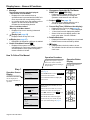
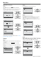
How To Follow This Manual
Operation Procedure
Explains the sequence of operation for the remote controller.
Operate the buttons according to
the procedure.
Step 1.
Main Menu
Operation Screen
Display
Describes screens that
will be displayed on
the remote controller in
operation.
Step 2.
1/2
Schedule
Off Timer
Celsius / Fahrenheit
Maintenance Information
Setting
Schedule
Clock has not been set.
Would you like to set it now?
Yes
No
Setting
Date & Time
Year 2008
Month 01
Day
01
Tuesday
12:00 A
Setting
Page 8 of 36 / OM 1169-1
Display the main menu screen.
(See page 9).
Press ▲▼ buttons to select Schedule
in the main menu screen.
Press Menu/OK button to display the
timer screen.
Before setting the schedule, the clock
must be set.
If the clock has not been set, a screen
like the one on the left will appear.
Press◄► buttons to select Yes and
press Menu/OK button.
The date & time screen will appear.
Set the current year, month, day and
time. (See clock settings on page 10.
Operation Button
Display
Displays the buttons to
be operated.
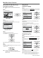
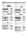
Main Menu Screen Overview
Moving Within The Main Menu Screen
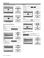
Setup Guide
Display Method For Main Menu
Setting The Language
Note: Pushing any button for the first time activates the back
light.
Press Menu/OK button, the “Main Menu” screen will appear.
Press ▼▲ buttons to select Language on the main menu
screen and press the Menu/OK button.
Step 1.
Press Menu/OK button.
Cool
Return
Step 1.
Main Menu
Set to
Cool 74F
2/2
Configuration
Current Settings
Clock & Calendar
Daylight Saving Time
Language
Setting
Setting
Basic screen
Step 2.
The “Main Menu” screen will appear.
Instructions for moving within the main menu will appear.
Main Menu
1/2
Schedule
Off Timer
Celsius / Fahrenheit
Maintenance Information
Setting
Main menu screen
Step 3.
Selecting items from the main menu.
Press ▼▲buttons to select the desired item to be set.
Step 2.
Press ▼▲ buttons to select the preferred language on the
language screen.
English/Français/Español are available.
Press Menu/OK button to confirm the settings and return to
the basic screen.
Language
English
Setting
Daylight Savings Time
Step 1.
Press Menu/OK button, the “Main Menu” screen will appear.
Step 2.
Press ▼ button to select Daylight Savings Time and press
Menu/OK button, the “Daylight Savings Time” screen will
appear.
Press Menu/OK button to display the details for the selected
item.
Step 4.
To go back to the Basic Screen from the main menu, press the
“Cancel” button.
Note: If a button is not pressed for 5 minutes during
configuration, the controller will automatically revert to
the basic screen.
Main Menu
2/2
Maintenance Information
Configuration
Current Settings
Clock & Calendar
Daylight Saving Time
Language
Setting
Step 3.
Press ▼ button to observe DST ON and press Menu/OK
button. Otherwise, set it to off.
ON sets the clock one hour ahead and OFF restores it.
Note: DST clock correction is not automatically adjusted by
calendar. It must be enabled/disabled manually.
Page 9 of 36 / OM 1169-1
Setup Guide
Daylight Savings Time (Continued)
Daylight Saving Time
Observe Daylight Saving Time
ON
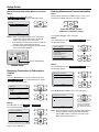
Step 4.
By default, the time display is set to the 12H format.
Press ▼▲ buttons to select 12H
24H on the 12H/24H
clock screen.
The confirmation screen will appear when the Menu/OK button is pressed.
12H/24H Clock
Setting
Clock is set one hour ahead
12H
Daylight Saving Time
Setting
Observe Daylight Saving Time
OFF
Step 5.
Press ◄► buttons to select Yes on the confirmation screen.
Pressing the Menu/OK button confirms the 12H or 24H and
takes you back to the main menu screen.
Setting
Clock is restored
Setting The 12H/24H Clock
Step 1.
Press Menu/OK button, the “Main Menu” screen will appear.
Step 2.
Press ▼▲ buttons to select Clock & Calendar on the main
menu screen.
Press Menu/OK button to display the clock & calendar screen.
Main Menu
2/2
Configuration
Current Settings
Clock & Calendar
Daylight Saving Time
Language
Setting
Step 3.
Press ▼▲ buttons to select 12H/24H Clock on the “Clock
& Calendar” screen.
The “12H/24H Clock” screen will appear when the Menu/
OK button is pressed.
Clock & Calendar
Date & Time
12H/24H Clock
Setting
Page 10 of 36 / OM 1169-1
12H/24H Clock
Save the settings?
Yes
No
Setting
Setting The Date & Time
Step 1.
From the Main Menu screen, press ▼▲ buttons to select
Clock & Calendar on the main menu screen.
Press Menu/OK button to display the “Clock & Calendar”
screen.
Main Menu
2/2
Configuration
Current Settings
Clock & Calendar
Daylight Saving Time
Language
Setting
Setup Guide
Setting The Date & Time (Continued)
Step 2.
Press ▼▲ buttons to select Date & Time on the clock &
calendar screen.
Press Menu/OK button to display the “Date & Time” screen.
Clock & Calendar
Date & Time
12H/24H Clock
Step 6.
Select “Hour” with ◄► buttons. Change the hour with ▼▲
buttons.
Holding down the button causes the number to change continuously.
Date & Time
Year 2009
Month 10
Day
07
Thursday
12:00 A
Setting
Setting
Step 3.
Select “Year” with ◄► buttons. Change the year with ▼▲
buttons.
Holding down the button causes the number to change continuously.
Date & Time
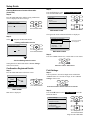
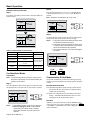
Standard and Detailed Display Modes
Displaying Room Temperature, Day, and Time
The Liquid Crystal Display (LCD) screen offers two display
modes. The Standard Display (below) is set by default.
Auto
Year 2008
Month 01
Day
01
Thursday
Set to
Cool 70F
Heat 64F
12:00 A
Return
Setting
Step 4.
Select “Month” with ◄► buttons. Change the month with
▼▲ buttons.
Holding down the button causes the number to change continuously.
Date & Time
Year 2009
Month 10
Day
01
Thursday
Setting
Standard display
If you want to display Room Temperature and/or Day and
Time, Detailed Display should be selected.
Select Detailed Display as follows.
Step 1.
In main menu, press ▼ button to select Configuration and
press Menu/OK button.
Main Menu
12:00 A
Setting
Step 5.
Select “Day” with ◄► buttons. Change the day with ▼▲
buttons.
Holding down the button causes the number to change
continuously. Days of the week change automatically.
2/2
Maintenance Information
Configuration
Current Settings
Clock & Calendar
Daylight Saving Time
Language
Setting
Step 2.
In “Configuration” screen, press ▼ to select Display and
press Menu/OK button.
Configuration
Date & Time
Contrast Adjustment
Display
Year 2009
Month 10
Day
07
Thursday
12:00 A
Setting
Setting
Page 11 of 36 / OM 1169-1
Setup Guide
Standard and Detailed Display Modes (Continued)
Entering Maintenance Contact Information
Step 3.
In “Display” screen, press ▼ to select
Display Mode - Detailed and press Menu/OK button.
Step 1.
From the Basic (Standard or detailed display) screen, press
and hold the “Cancel” button for 4 seconds or longer.
Display
Display Mode
Display Item
Detailed
Room
Press and hold the “Cancel”
button for 4 seconds or longer
Setting
Notes:1.When in the detailed display menu, select room temperature. The two other items; “Outside Air Temp”. and “System”, are for future use.
2.The displayed contents of the screen vary with the operation mode of the WSHP unit model.
3.The following display will appear when the WSHP unit is in automatic operation:
Auto
Sun
11:48P
Room
73F
Return
Set to
Cool 70F
Heat 64F
The “Service Settings” menu will appear.
Step 2.
Press the ▼ button to select Maintenance Contact . Press
the Menu/OK button.
Service Settings
1/3
Test Operation
Maintenance Contact
Field Settings
Energy Saving Options
Prohibit Buttons
Min Setpoints Differential
Setting
Room Temp display
Setting
Detailed display
Displaying Temperature In Fahrenheit or
Celsius
Step 1.
From the “Main Menu” screen, press ▼ button to select
Celsius / Fahrenheit . Press Menu/OK button to display
the Celsius / Fahrenheit screen.
Step 3.
Press the ▼ button to select Maintenance Contact . Press
the Menu/OK button.
Maintenance Contact
None
Maintenance Contact
Setting
Main Menu
1/2
Quick Start
Schedule
Off Timer
Celsius / Fahrenheit
Filter Auto Clean
The “Maintenance Contact” entry screen will appear.
Maintenance Contact
Setting
_________________
Step 2.
Press ▼ button to select Celsius or Fahrenheit .
Press Menu/OK button to select.
Celsius / Fahrenheit
Celsius / Fahrenheit
Fahrenheit
Setting
Page 12 of 36 / OM 1169-1
Setting
Enter the telephone
number. Scroll through
the numbers with the
▲▼ (Up/Down) buttons.
Note: Enter the telephone number using the ▲▼ buttons to
scroll through the numbers. Start from the left side.
Use the ◄► buttons to shift the cursor left or right.
Blank digits should remain as “–”.
Setup Guide
Entering Maintenance Contact Information
(Continued)
Step 4.
Press the Menu/OK button, and the setting confirmation
screen is displayed as shown in Step 5.
Maintenance Contact
0123–45––––––––––
Step 2.
Press the ▼ button to select Maintenance Information .
Press the Menu/OK button.
Main Menu
1/2
Schedule
Off Timer
Celsius / Fahrenheit
Maintenance Information
Setting
Press Menu/OK button.
Main menu screen
Setting
The registered contact information details are displayed.
Step 5.
Select Yes and press the Menu/OK button.
<Setting confirmation screen>
Maintenance Contact
Save the settings?
Maintenance Information
Contact Info
0123-456-7890
Registered details
are displayed.
Indoor Model ——/000
Outdoor Model ——/000
Setting
Yes
No
Press Menu/OK button.
Main menu screen
Step 3.
Press the “Cancel” button twice, and the basic screen returns.
Setting
▼
<Service Settings menu screen>
Setting details are determined and the “Service Settings”
menu screen returns.
Confirmation Registered Details
Step 1.
Press the Menu/OK button in the basic screen.
Cool
Return
Set to
Cool 68F
Setting
Basic screen
Main menu is displayed.
Press Menu/OK button.
Press the “Cancel” button twice.
Field Settings
Step 1.
Push any button to activate backlight. Press and hold the
“Cancel” button for 4 seconds or longer, to enter “Service
Settings” menu screen.
Press and hold the “Cancel” button for 4 seconds.
Step 2.
Press the ▲▼ button to select Field Settings . Press the
Menu/OK button.
Service Settings
1/3
Test Operation
Maintenance Contact
Field Settings
Energy Saving Options
Prohibit Buttons
Min Setpoints Differential
Setting
Press Menu/OK button.
Page 13 of 36 / OM 1169-1
Setup Guide
Field Settings (Continued)
Step 3.
Select Field Settings by pressing the ◄ ► buttons to select
items, and the ▲▼ buttons to select value. Press ◄► buttons to select Mode number. Refer to Table 14 on page 15.
Field Settings
Unit No.
0 –
0-01 –
4–––
8–––
Mode
20
1-01
2-02
5––– 6–––
9––– a–––
Step 5.
Press the Menu/OK button, and the confirmation screen is
displayed. Select Yes and press the Menu/OK button.
Field Settings
Save the settings?
Yes
3-01
7–––
b–––
Use the ◄ and ► buttons to
select items.
No
Press Menu/OK button.
Setting
Setting Confirmation
Setting details are determined and the “Field Settings” screen
returns. In the case of multiple setting changes, repeat “Step 1
through Step 5”.
Setting
Use the ▲ and ▼ buttons to
select the value.
Step 4.
Press the ◄ or ► buttons to highlight the SECOND CODE
NO. of the FIRST CODE NO. to be changed.
Step 7.
After all setting changes are completed, press the “Cancel”
button twice.
Field Settings
Unit No.
0 –
0-01 –
4–––
8–––
Mode
10
1-+
2-+
5–––
6–––
9–––
a–––
Press the “Cancel” button twice.
3-+
7–––
b–––
Press Menu/OK button.
Setting
Note: 1.Installation of optional accessories on the unit may require changes to field settings. See the manual for the optional accessory.
2.For field setting details related to the unit, see the
installation manual shipped with the unit.
Second Code No.
First Code No.
Step 5.
Press the ▲or▼ button to change the Second Code to its new
value. Refer to Table 14 on page 15
Field Settings
Unit No.
0 –
0-01 –
4-03
8–––
Mode
10
1-+
2-+
5–––
6–––
9–––
a–––
3-+
7–––
b–––
Setting
Second Code No.
First Code No.
Note: When the SECOND CODE NO. is displayed as “–”, there is no function.
Page 14 of 36 / OM 1169-1
Backlight goes out, and “Checking the connection. Please
stand by” is displayed for initialization. After the initialization, the basic screen returns.
Regarding Specific Field Setting Changes
NOTICE
In the next three sections, “Setting The Fan Mode”, “Enabling
Setback Temperature Control”, and “Activating Filter Change Indicator”, a shorthand notation is used to refer to the Mode Number, First Code No., and Second Code No.
For example, “22-06-02” means, (Mode 22 - First Code No. 06 Second Code No. 02)
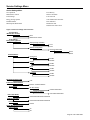
Setup Guide
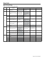
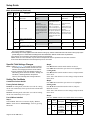
Mode & Code Settings
Table 14: Unit & remote controller field settings
Mode No.
(Note 1)
1b
1c
First Code
No.
Second Code No. (Note 2) (Tinted cells are factory default settings)
Description
01
02
03
04
7
STANDBY icon
Display in Defrost or Hot
Start
1
Thermistor sensor used for
Auto-changeover and Setback
control
Return Air Thermistor
return air temperature
displayed on controller
as room temperature
Remote Controller Thermistor - remote controller
temperature displayed
on controller as room
temperature
‒‒
‒‒
2
Setback availability
N/A
Heating mode only
Cooling mode only
Cooling/Heating modes
4
Schedule and Auto-changeover
enabled when multi zone controller is detected (Note 1)
No
Yes
‒‒
‒‒
9
CENTRAL CONTROL icon
Not displayed
Displayed when under
control by a multi zone
controller
10
Message when button pushed
which has been prohibited by a
multi zone controller
Key lock icon blinks for 5
seconds
Message displayed on
screen: “Under Centralized Control - Adjustments
at the remote controller
are being restricted.”
11
Auto-changeover guard timer
interval
15 minutes
30 minutes
60 minutes
90 minutes
2
Priority of thermistor sensors for
space temperature control.
The return air
thermistor is primary
and the remote
controller thermistor
Is secondary.
Only the return air thermistor will be utilized.
Only the remote controller thermistor will be
utilized.
–
5
Room temperature value reported to multi zone controllers.
Return air thermistor
Thermistor designated by
10-2 above (Note 3).
–
–
6
The remote controller thermistor
is used in Remote Controller
Group.
No
Yes
–
–
Number of stages of electric
heater
1
2
3
1e
20
Not displayed
3
5
21
6
7
8
9
Page 15 of 36 / OM 1169-1
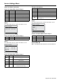
Setup Guide
Mode & Code Settings (Continued)
Mode No.
(Note 1)
First Code
No.
0
Second Code No. (Note 2) (Tinted cells are factory default settings)
Description
01
KRP1B71 X1-X2
status output
02
03
04
Unit Thermistor On/Off
status.
–
Indoor unit operation
On/Off status
On/Off
Closed Contact–Unit is
turned off.
Unit responds to last command, i.e., unit can be
turned on manually or by
central control after circuit
has opened. Operation is
prohibited when remote
controller On/Off control is
restricted by a multi zone
controller.
External Protection
Device
Closed contact–unit
shall resume normal
operation.
Open contact–unit
shall shut down and
generate an A0 error.
Unit Alarm status
1
Unit T1-T2 input
Forced Off
Closed Contact – Unit
is forced off and Central
Control icon is displayed.
Unit cannot be turned on
manually. Operation can
be overridden by central
control.
2
Thermo-On/Off dead band
(Note 4).
2F (1C)
1F (0.5C)
–
–
3
Fan Speed in Heating ThermoOff
LL
User set
Off
–
6
Fan Speed in Cooling ThermoOff
LL
User set
Off
–
22
Notes:1.Native remote controller Schedule and Auto-changeover functions are disabled when a multi zone controller is detected
and a group address is assigned.
2.Field settings are normally applied to the entire remote control group, however if individual units in the remote control group require
specific settings or for confirmation that settings have been established, utilize the mode number in parenthesis.
3.Any features not supported by the installed unit will not be displayed.
4.When mode 10-2-01 is selected, only the return air temperature value is reported to the multi zone controller.
5.The actual default dead band value will depend upon the unit model.
Specific Field Settings Changes
Notes:1Refer to page 13 - 14 for a step by step procedure for selecting the Mode Number and the First Code Number, and changing the Second Code Number.
2.For the remainder of the Field Settings section [or alternatively] In the next three sections, “Setting The Fan Mode”, “Enabling Setback Temperature
Control”, and “Activating Filter Change Indicator”
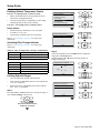
Setting The Fan Mode
Continuous Or Auto On/Off
Factory Default Settings:
22-06-02: In cooling mode, when there is no call for cooling,
the fan runs continuously at the speed selected on the Remote
Controller.
22-03-01: In heating mode, when there is no call for heating,
the fan runs continuously at low speed.
Fan Off When Satisfied
Step 1.
Hold “Cancel” button for 5 seconds to display “Service
Menu”. Scroll down to “Field Settings”. Select by pressing
Menu/OK.
Step 2.
Press▲▼ buttons until the mode number reaches 22.
Press ◄► buttons until the space next to 06 is highlighted
(cooling mode)
Press▲▼ buttons until the number reads 03, and press Menu/
OK to select.
Select “Yes” when asked to save the settings, and press Menu/
OK to select.
Step 3.
Press ◄► buttons until the space next to 03 is highlighted
(heating mode)
Press ▲▼ buttons until the number reads 03, and press
Menu/OK to select.
Select “Yes” when asked to save the settings, and press Menu/
OK to select.
Step 4.
Press the “Cancel” button twice, and the basic screen returns.
Mode
Second Code No.
First
Code No.
Description
01
02
03
3
Fan Speed
in Heating
Thermo-Off
LL
User set
Off
6
Fan Speed
in Cooling
Thermo-Off
LL
User set
Off
22
Page 16 of 36 / OM 1169-1
Setup Guide
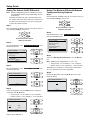
Enabling Setback Temperature Control
Unit On = Occupied period = Comfort Control
• Indoor unit maintains the room temperature at the setpoint in the cooling/heating mode
• Comfort setpoint range is configurable in each cooling
and heating mode on the remote controller
Unit Off = Unoccupied period = Setback Control
Enable Setback
• Setback function is disabled (1e-2-01) by default
• To enable it, set 1e-2-04
• Field setting is available in the Service Settings
Refer to “Field Settings” on page 13 for step-by step
instructions.
Service Settings
1/3
Test Operation
Maintenance Contact
Field Settings
Energy Saving Options
Prohibit Buttons
Min Setpoints Differential
Setting
▼
Energy Saving Options
Setpoint Range Limitation
Setback Configuration
Activating Filter Change Indicator
Refer to “Field Settings” on page 13 for step-by step
instructions.
Table 15: “Time to change filter” message; enable/disable
Code
“Time to change filter” message
20-3-01
Enabled by default
20-3-02
Disabled
Table 16: “Time to change filter” message settings
Code
“Time to change filter” message
20-0-2 and 20-1-1
Displays after 1250 hours
20-0-1 and 20-1-1
Displays after 2500 hours
20-0-2 and 20-1-2
Displays after 5000 hours
20-0-1 and 20-1-2
Displays after 10,000 hours
Setting
Step 2.
Select the temperature item with ◄► buttons. Change the
temperature with ▼▲ buttons.
Holding down the ▼ or▲ button causes the number to
change continuously.
Setpoint Range Limitation
Cool
–
–
Heat
70 F
–
80 F
64 F
–
74 F
Setting
Limiting Setpoint Ranges
•
•
•
User can change the setpoint within the range
Setup setpoint is configurable between Cool setpoint max
+ 2°F (1°C) and 95°F
Setback setpoint is configurable between Heat setpoint
min – 2°F ( 1°C) and 40°F
Step 1.
Press and hold the “Cancel” button for 4 seconds or longer, to
enter “Service Settings” menu screen.
Energy Saving Options
Setpoint Range Limitation
Setback Configuration
Setting
▼
Press and hold the “Cancel”
button for 4 seconds.
▼
Page 17 of 36 / OM 1169-1
Setup Guide
Setting The Setback On/Off Differential
Note: Setback Configuration won’t be available if you have
not enabled the setback control (Field setting 1e-2-04
is necessary).
•
Determine the point when unit is turned off again from
the setback control (the unit is turned on by setback control when room temperature is above the setup setpoint
or below the setback setpoint)
Step 1.
Press and hold the “Cancel” button for 4 seconds or longer, to
enter “Service Settings” menu screen.
Setting The Minimum Differential Between
Cooling and Heating Setpoints
Step 1.
Press and hold the “Cancel” button for 4 seconds or longer, to
enter “Service Settings” menu screen.
Press and hold the “Cancel”
button for 4 seconds.
Step 2.
Press the ▼ button to select Min Setpoints Differential .
Press the Menu/OK button.
Press and hold the “Cancel”
button for 4 seconds.
Step 2.
Press the ▼ button to select Energy Saving Options . Press
the Menu/OK button.
Service Settings
1/3
Test Operation
Maintenance Contact
Field Settings
Energy Saving Options
Prohibit Buttons
Min Setpoints Differential
Setting
Step 3.
Press the ▼ button to select Setback Configuration . Press
the Menu/OK button.
Energy Saving Options
Setpoint Range Limitation
Setback Configuration
Service Settings
1/3
Test Operation
Maintenance Contact
Field Settings
Energy Saving Options
Prohibit Buttons
Min Setpoints Differential
Setting
Step 3.
Select the “Min Setpoints Differential” item with ▼▲ buttons.
Note: Default is 2°F, configurable 0 – 7°F (0 – 4°C)
• Setup setpoint - 4°F as default (2 - 10°F selectable)
• Setback setpoint + 4°F as default (2 - 10°F selectable)
When Multi zone controller is connected, the differential is
set to 0°F automatically and is not adjustable.
Step 4.
Change the differential value with ▼▲ buttons. Press the
Menu OK button.
Min Setpoint Differential
Setting
Step 4.
Select the temperature item with ◄► buttons. Change the
temperature with ▼▲ buttons.
• Setup setpoint - 4°F as default (2 - 10°F selectable)
• Setback setpoint + 4°F as default (2 - 10°F selectable)
Setpoint Configuration
Recovery Differential
–
–
Cool
Heat
– 4F
+ 4F
Setting
Page 18 of 36 / OM 1169-1
Min Setpoints Differential
–
2F
–
Setting
Press Menu/OK button.
Setup Guide
Prohibiting Remote Controller Keys
Step 1.
Press and hold the “Cancel” button for 4 seconds or longer, to
enter “Service Settings” menu screen.
Step 5.
To release it, same as in “Step 1.”. Then when the prohibited
(key) icon will blink three times.
button is pushed, the
Basic Operation
LCD (With Backlight)
Push any button to activate backlight, buttons then resume
normal operation. Backlight automatically turns off 30 seconds after last button push.
Press and hold the “Cancel”
button for 4 seconds.
Step 2.
Press the ▼ button to select Prohibit Buttons . Press the
Menu/OK button.
:
:
:
:
Enable
Enable
Enable
Disable
On/Off
Setting
Press Menu/OK button.
Step 3.
Press the ▼ button to select button item and ► button to
select Enable/Disable . Press the Menu/OK button.
Note: Menu/OK, Cancel and the prohibited button(s) will not
be available.
Prohibit Buttons
Up/Dwn/L/R
On/Off
Mode
Fan Speed
:
:
:
:
Enable
Enable
Enable
Disable
Prohibit Buttons
Up/Dwn/L/R
On/Off
Mode
Fan Speed
:
:
:
:
Enable
Enable
Enable
Disable
Setting
Step 4.
At the main display, holding ► button, push “Mode”, “Fan
Speed” and “Cancel” at the same time, and Access Level is
enabled.
12:10A
Tue
Room
73F
Return
Setting
Setback
Cool 95F
Heat 41F
Auto
12:10A
Tue
Room
73F
Return
Setting
nu
K
When the On/Off button is pressed again, the system will stop
operating and the operation lamp will turn off.
Notes: 1.When the system is stopped while in the heating
mode, the fan will continue to operate for
approximately one minute to remove residual heat from the WSHP unit.
2.To prevent water damage or system failure, do not immediately remove power from the WSHP unit
following system operation. Wait at least five minutes for the condensate pump to finish draining residual water from the unit.
Setback Feature
Setting
Auto
On/Off Button
Press On/Off button. The Operation lamp (green) will illuminate and the system will start operating.
Prohibit Buttons
Up/Dwn/L/R
On/Off
Mode
Fan Speed
Note: If two remote controllers are used to control a single
unit, only the controller to be accessed first will have
backlight functionality.
Setback
Cool 95F
Heat 41F
Unit On = Occupied period = Comfort control
• Indoor unit maintains the room temperature at the setpoint in the cooling/heating mode
• Comfort setpoint range is configurable in each cooling
and heating mode on the remote controller, see “Limiting
Setpoint Ranges” on page 17.
Unit Off = Unoccupied period = Setback control
• The remote controller maintains the room temperature
between the setup and setback setpoints, turning the unit
on/off when necessary
• Setpoints in the unit are not changed
The Setback feature will maintain the space temperature in a
specific range during unoccupied periods.
Notes: 1.This function will temporarily start a WSHP unit that was previously turned off by the user pressing the On/Off button on the remote controller, or turned off from a schedule event / off timer.
2.This function must be enabled by the user or
system installer. See “Enabling Setback Temperature Control” on page 17.
Page 19 of 36 / OM 1169-1
Basic Operation
Setback Feature (Continued)
Step 1.
The setback icon flashes when the unit is turned on under the
setback control.
Cool
Setback
Cool 84F
Return
Step 2.
The setpoint will increase by 1°F (or 1°C) when ▲ button
is pressed and decrease by 1°F (or 1°C) when ▼ button is
pressed.
Note: Setpoint is not available in fan or dry mode.
Cool
Set to
Cool 74F
Setting
Return
Step 3.
To change the fan speed, press the Fan speed control button
and select the desired fan speed from Low or High.
SETBACK
Cool
Setback
Cool 84F
Return
Notes: 1.The system may be in automatic fan speed control for equipment protection purposes.
2.The system may be in automatic fan speed control according to the room temperature. It is normal for the fan to intermittently stop operating.
3.It is normal for a delay to occur when changing the fan speed.
Setting
Table 17: Setback features and functions
Property
Values
Cool Setpoint Range
Configurable in 60-90°F
Setting
Function
Setpoint cannot be
set out of the range
Heat Setpoint Range
Configurable in 60-90°F
Setup Setpoint
Cool setpoint rang max. +2°F
to 95°F
Setback Setpoint
40°F to Heat setpoint range
min. -2°F
Schedule
Events (time, on/off, C/H setpoints or setback setpoints)
Alternative of
manual operation
Time clock
Day and time
48hr backup
Cool
Turn on/off the units
when necessary
Return
Low
Set to
Cool 74F
Setting
High
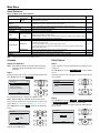
Cool/Heat/Auto Modes
Preparation
Note: For mechanical protection purposes, apply power to
the system units at least six hours before starting the
operation of the system.
Step 1.
Press the Operation mode selector button several times until
the desired mode, Cool, Heat, Fan or Auto mode is selected.
Cool
Return
Set to
Cool 74F
Setting
Notes: 1.Unavailable operation modes are not displayed.
2.
Before changing the mode, confirm that the
display does not indicate master controlled
status. Both heat and cool mode may not be
selected
Page 20 of 36 / OM 1169-1
Characteristics Of Heat Mode
The system automatically controls the following operating
modes to prevent the reduction of heating capacity and space
comfort.
Desuperheater Operation
The optional desuperheater pump will only operate in heating mode if the unit can provide more capacity than is
required for space heating.
See IOM 1160, “SmartSource Inverter Water Source Heat
Pumps -- Installation & Maintenance Data” for more
information on the Desuperheater option.
Hot Start
When the system goes into heat mode, the WSHP unit fan
will stop in order to prevent a cold draft. (In that case, “ STANDBY ”
“ STANDBY ” (Defrost/Hot start) will be displayed on the
remote controller.)
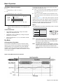
Basic Operation
On entering dry mode, the control system takes note of the
current Room Temperature (Tro).
■ If Tro > 76.1°F (24.5°C), the controller cycles on and off
in cooling mode to keep the room temperature between
Tro and (Tro-2.7°F).
■ If Tro ≤ 76.1°F, the controller cycles on and off in cooling mode to keep the room temperature between Tro and
(Tro-1.8°F).
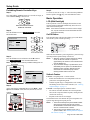
As shown in Figure 10, while in Dry Mode Operation, the fan
operates at low (L) flow rate, stops for a period of six minutes
while the thermostat is OFF, and then returns to operation at
(L) flow rate. (This control is used to prevent a rise in indoor
temperature while in thermostat OFF mode.)
Auto Mode in Remote Controller
H → C:
• Room temp. ≥ C_SP + 1°F (0.5°C)
C → H:
• Room temp ≤ H _ SP − 1°F (0.5°C)
C_SP
H_SP
─ ─ ─ ─ ─ ─ ─ ─ ─ ─ ─ ─ H → C
+1°F (0.5°C)
-1°F (0.5°C)
─ ─ ─ ─ ─ ─ ─ ─ ─ ─ ─ ─ C → H
Step 1.
Operation
Note: C_SP and H_SP can be set independently keeping the
minimum setpoint differential (0-7°F configurable, 2°F
default)
1 Hour Guard Timer
• Upon changeover, guard timer will prevent another
changeover during this period
• Guard timer can be overridden by a change of setpoint
manually or by schedule
• Timer is configurable to 15, 30, or 90 minutes with the
field setting
Dry Mode
Characteristics Of Dry Mode
The Dry Mode dehumidifies the space at reduced cooling
capacity to prevent the room temperature from dropping to
uncomfortable levels. In Dry Mode, the system maintains
automatic temperature and fan speed control. The fan only
operates at low, regardless of whether the controller is set for
low or high fan speed.
Press Mode button several times until the Dry mode is selected.
Dry
Return
Setting
Note: In Dry mode, the system maintains automatic temperature and fan speed control. Therefore, temperature
setpoint or fan speed settings are not available while
the WSHP unit is in the Dry mode.
Note: To prevent water damage or system failure, do not immediately remove power from the WSHP unit following
system operation. Wait at least five minutes for the
condensate pump to finish draining residual water from
the unit.
Figure 10: Dry Mode sequence of operation
Page 21 of 36 / OM 1169-1
Basic Operation
Key Lock
Note: Confirm and cancel Key Lock settings in the basic
display screen. Refer to Figure 11
Step 1.
Press the Menu/OK button for at least four seconds. (While
the backlight is illuminated).
Cool
Return
Step 2.
“ ” will appear. All buttons are disabled when the keys are
locked.
To cancel the key lock mode, continue pressing Menu/OK
button for at least four seconds. (While the backlight is illuminated).
Cool
Set to
Cool 74F
Return
Setting
Set to
Cool 74F
Setting
Basic screen
Figure 11: Menu Structure Example
Menu/OK for 5 sec.
Menu/OK
Basic Display
(Standard or Detailed) Screen
Key Lock
(Child Lock)
Menu/OK for 5 sec.
Cancel
Cancel for 5 seconds
Cancel
Service Settings Menu
Cancel for 5 seconds
Cancel
Maintenance Menu
Page 22 of 36 / OM 1169-1
Main
Menu
Main Menu
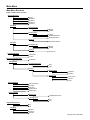
Main Menu Structure
Figure 12: Main menu structure
Air Flow Direction
Swing
Position 0
Position 1
Position 3
Position 4
Schedule
Enable/Disable
Enable
Disable
Daily Patterns
7 Days
Weekday/Weekend
Weekday/Sat/Sun
Settings
Time/Act/Cool/Heat
Off Timer
Enable/Disable
Enable
Disable
Settings
30-180 min.
Fahrenheit/Celsius
Fahrenheit
Celsius
Maintenance Information
Unit Model
Configuration
Contrast Adjustment
Dark
Light
Display
Display Mode
Display Item
Current Settings
Airflow Direction
Schedule
Off Timer
Display Mode
Display Item
Clock Calendar
Date & Time
Year/Month/Day/Time
12H/24H Clock
12H
24H
Daylight Saving Time
On
Off
Language
English
Français
Español
Standard
Detailed
Room Temp
System
None
Page 23 of 36 / OM 1169-1
Main Menu
Quick Reference
Figure 13: Main menu quick reference
Menu Item
Description
Daily Patterns
Settings
Schedule
Page
Used to schedule the dates and times of events such as set point changes and turning the controller off
(unoccupied) or on (occupied).
See below
Off Timer
Used to set each operation period of the system.
Possible to set in 10 minute increments from 30 to 180 minutes.
page 27
Celsius / Fahrenheit
Used to select whether temperature values will be displayed in Celsius or Fahrenheit.
page 12
Maintenance Information
Used to display the maintenance information.
page 12
Configuration
Used to make LCD contrast adjustment.
page 28
Used to set standard or detailed display mode.
Display mode (Standard or detailed display).
Detailed display provides the choice to display between Room Temp, Outside Air Temp, System or None.
page 11
Used to display a list of current settings for available items.
page 30
Date & Time
Used to configure date and time settings and corrections.
The default time display is 12H.
The clock will maintain accuracy to within ±30 seconds per month.
If there is a power failure for a period not exceeding 48 hours, the clock will continue working with the
built-in backup power supply.
page 10
12H/24H Clock
The time can be displayed in either a 12 hour or 24 hour time format.
page 10
Daylight Saving Time
Used to adjust the clock in observance of daylight saving time.
page 9
Language
The display language can be selected between English, Français or Español.
page 9
Contrast Adjustment
Standard or Detailed
Display
Display
Current Settings
Clock & Calendar
Note:
Available setting items vary with the WSHP unit model.
Schedule
Daily Patterns
Setting The Schedule
Step 1.
Select “Schedule” from the Main Menu. The schedule screen
will appear.
Press ▼▲ buttons to select Daily Patterns on the schedule
screen.
The daily patterns screen will appear when the Menu/OK button is pressed.
Note: The schedule cannot be enabled when a multi zone
controller such as the Intelligent Touch controller is
connected.
Step 1.
Display the main menu screen by pressing the Menu/OK button.
Press ▼▲ buttons to select Schedule .
Main Menu
1/2
Schedule
Off Timer
Celsius / Fahrenheit
Maintenance Information
Schedule
2/2
Enable/Disable
Daily Patterns
Settings
Setting
Setting
Press Menu/OK button to display the schedule screen.
Note: Before setting the schedule, the clock must be set.
If the clock has not been set, a screen like the one below will
appear. Refer to “Setting The 12H/24H Clock” on page 10.
Press ◄► buttons to select Yes and press the Menu/OK
button.
Step 2.
Press ▼▲ buttons to select 7 Days , Weekday/Weekend
or Weekday/Sat/Sun on the daily patterns screen.
The confirmation screen will appear when the Menu/OK button is pressed.
Schedule
Schedule
Clock has not been set.
Would you like to set it now?
Yes
No
Setting
Page 24 of 36 / OM 1169-1
Daily Patterns
7 Days
Setting
Main Menu
Daily Patterns (Continued)
Step 3.
Press ◄► buttons to select Yes on the confirmation
screen.
Pressing the Menu/OK button enters the daily patterns in the
schedule and takes you back to the main menu screen.
Step 2.
Press ▼▲ buttons to select the day to be set.
Schedule
Mon
Schedule
Time
– – :– –
– – :– –
– – :– –
– – :– –
– – :– –
Act
––
––
––
––
––
No
–
–
–
–
–
Step 3.
Input the time for the selected day.
Press ◄► buttons to move the highlighted item and press
▼▲ buttons to input the desired operation start time.
Each press of ▼▲ buttons moves the numbers by 1 hour or
1 minute.
Setting
Schedule
Clock has not been set.
Would you like to set it now?
Yes
Heat
–
–
–
–
–
Setting
Save the settings?
Yes
Cool
Schedule
No
Mon
Setting
Time
– 6 :00 A
– – :– –
– – :– –
– – :– –
– – :– –
Act
––
––
––
––
––
Setting
Cool
Heat
–
–
–
–
–
–
–
–
–
–
Cool
Heat
–
–
–
–
–
–
–
–
–
–
Date & Time
Year 2008
Month 01
Day
01
Tuesday
Schedule
Mon
12 : 00 A
Setting
The date & time screen will appear.
Set the current year, month, day, and time. Refer to “Setting
The Date & Time” on page 10)
Settings
Step 1.
Select “Schedule” from the main menu. The schedule screen
will appear.
Press ▼▲ buttons to select Settings on the schedule
screen.
The settings screen will appear when the Menu/OK button is
pressed.
Schedule
Time
– 6 :00 A
– – :– –
– – :– –
– – :– –
– – :– –
Act
––
––
––
––
––
Setting
Step 4.
Press the ◄► buttons to move the highlighted item and press
▼▲ buttons to configure ON/OFF/-- settings. --, ON, or OFF
changes in sequence when ▼▲ buttons are pressed.
Schedule
Mon
Time
– 6 :00 A
– – :– –
– – :– –
– – :– –
– – :– –
Act
––
––
––
––
––
Setting
Cool
Heat
–
–
–
–
–
–
–
–
–
–
Cool
90F
Heat
60F
–
–
–
–
–
–
–
–
2/2
Enable/Disable
Daily Patterns
Settings
Schedule
Mon
Setting
Time
– 6 :00 A
– – :– –
– – :– –
– – :– –
– – :– –
Act
ON
––
––
––
––
Setting
Page 25 of 36 / OM 1169-1
– 5 :30 P ON
1 0 :00 P – –
– – :– – – –
Setting
75F
70F
–
–
–
–
Cool
75F
85F
75F
82F
Heat
70F
50F
70F
62F
–
–
Cool
75F
85F
75F
82F
Heat
70F
50F
70F
62F
–
–
Main Menu
Settings (Continued)
ON: The temperature setpoints can be configured.
OFF: The setback temperature setpoints can be configured.
– –: The temperature setpoints and setback temperature setpoints become disabled.
Schedule
Mon
Time
– 6 :00 A
– 8 :00 A
– 5 :30 P
1 0 :00 P
– – :– –
Setting
Schedule
Mon
Time
– 6 :00 A
– 8 :00 A
– – :– –
– – :– –
– – :– –
Act
ON
OFF
––
––
––
Cool
75F
––F
Setting
–
–
–
Heat
70F
–
–
–
–
Schedule
Tue
The cooling and heating temperature setpoints for both ON
and OFF (Setback) are configured.
“_”: Indicates that the temperature setpoint and setback temperature setpoint for this time period is not specified. The last
active setpoint will be utilized.
“--”: Indicates that the setback function is disabled for this
time period.
Step 5.
A maximum of five actions per day can be set.
Press the Menu/OK button when settings for each day are
completed.
Schedule
Mon
Time
– 6 :00 A
– 8 :00 A
– 5 :30 P
1 0 :00 P
– – :– –
Act
ON
OFF
ON
––
––
Setting
Act
ON
OFF
ON
OFF
––
Cool
75F
85F
75F
Heat
70F
50F
70F
–
–
–
–
Time
– 6 :00 A
– 8 :00 A
– 5 :30 P
1 0 :00 P
– – :– –
Act
ON
OFF
ON
OFF
––
Setting
The confirmation screen will appear. To copy the settings for
the previous day, press the Mode button so that the existing
settings will be copied.
Example: The contents for Monday are copied by pressing
the Mode button after selecting Tuesday.
Step 6.
Press ◄► buttons to select “Yes” on the confirmation screen.
Pressing the Menu/OK button confirms the settings for each
day and takes you back to the main menu screen.
Schedule
Save the settings?
Yes
No
Setting
Schedule
Mon
Time
– 6 :00 A
– 8 :00 A
– 5 :30 P
1 0 :00 P
– – :– –
Act
ON
OFF
ON
OFF
––
Setting
Cool
75F
85F
75F
82F
Heat
70F
50F
70F
62F
Step 7.
–
–
Press the ▼▲ buttons to select WKDY and◄► buttons to select
“Event”. Press ▼▲ buttons to set “Cool” and “Heat” setpoint values.
Note: The example in Figure 14 assumes “Weekday/Weekend” or “Weekday/Sat/Sun” has been selected as the
“Daily Patterns” setting.
Figure 14: Daily patterns example
Schedule
Tue
Time
– 6 :00 A
– 8 :00 A
– 5 :30 P
1 0 :00 P
– – :– –
Schedule
Act
Cool
Heat
Time 70F
Act
ON
75F
OFF
ON
– 7 :00 A50F
WKDY 85F
ON
75F
– 8 :00 A70F
ON
82F
OFF
8 :00A62F
ON
––
OFF
9 :00A–
–
Setting
1 0 :00A OFF
Example
Cool
–
74F
74F
86F
––F
Heat
–
–
68F
62F
–
No setpoints are specified, just turn on the unit with the latest setpoints.
Only cool setpoint is specified, the latest setpoint is used.
Both cool and heat setpoints are specified.
Both setup and setback setpoints are specified.
No setup control (just turn off) and the latest setback setpoint is used.
Setting
No setpoint or setup/setback setpoint is specified. The latest value is used.
Disable setup/setback setpoint and the unit is kept turned off.
Note:
“Event” in the schedule is to carry out for the manual operation at the time.
Page 26 of 36 / OM 1169-1
Main Menu
Enabling or Disabling The Schedule
Off Timer
Step 1.
Display the schedule screen. (See “Setting The Schedule” on
page 24.)
Press ▼▲ buttons to select Enable/Disable on the schedule screen.
Press Menu/OK button to display the enable/disable screen.
Configuring And Confirming The Off Timer Settings
Schedule
Step 1.
Display the main menu screen by pressing the Menu/OK button.
Press ▼▲ buttons to select the Off Timer on the main
menu screen.
Press Menu/OK button to display the off timer screen.
2/2
Enable/Disable
Daily Patterns
Settings
Main Menu
1/2
Schedule
Off Timer
Celsius / Fahrenheit
Maintenance Information
Setting
Setting
Step 2.
Press ▼▲ buttons to select Enable or Disable on the
enable/disable screen.
Press Menu/OK button after selecting the item. The confirmation screen will appear.
Step 2.
Press ▼▲ buttons to select Settings on the off timer
screen.
Press Menu/OK button to display the configuration screen.
Off Timer
Off Timer
Enable/Disable
Enable/Disable
Settings
Disable
Setting
Step 3.
Press ◄► buttons to select Yes on the confirmation
screen.
Pressing Menu/OK button confirms the enable/disable setting
for the schedule and takes you back to the basic screen.
Off Timer
1/2
Setting
Step 3.
Use ▼▲ buttons to set the time from operation start until the
unit automatically stops.
Selections can be made in increments of 10 minutes from 30
to 180 minutes.
Holding down the button causes the number to change continuously.
Save the settings?
Off Timer
Yes
No
Setting
After you turn on the unit,
it will automatically
turn off in
60 minutes.
Setting
Select the desired time and press Menu/OK button.
The confirmation screen will appear.
Page 27 of 36 / OM 1169-1
Main Menu
Off Timer (Continued)
Additional Main Menu Information
Step 4.
Press ◄► button to select Yes on the confirmation screen.
Pressing Menu/OK button confirms the off timer and takes
you back to the basic screen.
See Reference Page:
Off Timer
Page
Fahrenheit / Celsius
page 12
Maintenance Information
Configuration
Save the settings?
Yes
Menu Description
No
Setting
page 12
Contrast Adjustment
Display
Below
page 11 & page 29
Clock & Calendar
page 10
Date & Time
page 10
12H / 24H Clock
page 10
Daylight Savings Time
page 9
Language
page 9
Enabling Or Disabling The Off Timer
Contrast Adjustment
Step 1.
Navigate to the off timer screen. (See “Configuring And Confirming The Off Timer Settings” on page 27.)
Press ▼▲ buttons to select Enable / Disable on the off
timer screen.
Press Menu/OK button to display the enable/disable screen.
Step 1.
Display the main menu screen.
Press ▼▲ buttons to select Configuration on the main
menu screen.
Press Menu/OK button to display the configuration screen.
Main Menu
Off Timer
1/2
Enable/Disable
Settings
2/2
Configuration
Current Settings
Clock & Calendar
Daylight Saving Time
Language
Setting
Setting
Step 2.
Press ▼▲ buttons to select Enable or Disable on the
enable/disable screen.
Press Menu/OK button after selecting the item. Then the confirmation screen will appear.
Step 3.
Press ◄► button to select Yes on the confirmation screen.
Pressing Menu/OK button confirms the enable/disable for the
off timer and takes you back to the basic screen.
Step 2.
Navigate to the configuration screen.
Press ▼▲ buttons to select Contrast Adjustment on the
configuration screen.
Press Menu/OK button to display the contrast adjustment screen.
Step 3.
On the contrast adjustment screen press ▼▲ buttons until
you reach the desired contrast.
After setting, press Menu/OK button and return to the basic
screen.
Contrast Adjustment
Off Timer
Save the settings?
Dark
Yes
No
Setting
Page 28 of 36 / OM 1169-1
Light
Setting
Main Menu
Display Mode
Display Item
Step 1.
Navigate to the configuration screen.
Press ▼▲ buttons to select Display on the configuration
screen.
Press Menu/OK button to display the display screen.
Step 1.
Navigate to the display screen, Main Menu
Configuration
Display.
Press ▼▲ buttons to select Display Item on the display
screen.
Press Menu/OK button to display the display item screen.
Configuration
Display
Contrast Adjustment
Display
Display Mode
Display Item
Standard
None
Setting
Setting
Step 2.
Press ▼▲ buttons to select Display Mode on the display
screen.
Press Menu/OK button to display the Display Mode screen.
Display
Display Mode
Display Item
Standard
None
Step 2.
Pressing ▼▲ buttons displays the following.
None ◄►*Outside Air Temp
*System ◄► Room Temp
* The SmartSource Inverter WSHP will not display these items
even if they are selected.
Be sure to read the following notes regarding display of room
temperature and outside air temperature.
Display
Setting
Display Item
None
Step 3.
Press ▼▲ buttons to select Standard or Detailed on the
display screen.
Press Menu/OK button to confirm the settings and return to
the basic screen.
Note: Refer to Display Item to change detailed display
selection.
Setting
Room Temp
The temperature at the remote controller. The temperature
that is detected may be affected by the location of the remote
controller.
Display
Display Mode
Standard
Setting
Page 29 of 36 / OM 1169-1
Main Menu
Current Settings
Maintenance
Viewing The Current Setting
Reset Filter Indicator
Step 1.
Display the main menu screen.
Press buttons to select Current Settings on the main menu
screen and press Menu/OK button.
Step 1.
When it is time to clean or replace the filter, one of the following messages will appear on the bottom of the basic screen.
“Time to clean filter”
“Time to clean filter & element”
“Time to clean element”
Main Menu
2/2
Configuration
Current Settings
Clock & Calendar
Daylight Saving Time
Language
Cool
Set to
Cool 74F
Setting
Time to clean filter
Step 2.
A list showing the current setting status will appear.
Press ◄► buttons to go to the next item.
Pressing the “Cancel” button takes you back to the main menu
screen.
Current Setting
Schedule
Off Timer
Display Mode
Display Items
1/2
Enable
Disable
Standard
None
Wash, clean, or replace the filter or element.
For details, refer to “Activating Filter Change Indicator” on
page 17.
Step 2.
Reset the filter indicator when the filter or element is cleaned
or replaced.
Press Menu/OK button. The main menu screen will appear.
Setting
Display Items
ScheduleEnable
Off Timer
Disable
Display Mode
Standard
Display Items
None
Note: Display items may differ depending on the model.
Only the items that can be set are displayed.
Step 3.
Press ▼▲ buttons to select Reset Filter Indicator on the
main menu screen and press Menu/Enter button.
Note: Reset Filter Indicator only appears on the Main Menu
when the “Time to clean filter” message is displayed at the bottom of the basic screen.
Main Menu
1/2
Reset Filter Indicator
Schedule
Off Timer
Celsius / Fahrenheit
Setting
Cool
Set to
Cool 74F
The message “Time to clean filter”, as shown in the illustration under Step 1, will disappear from the basic screen when
the filter indicator is reset.
Page 30 of 36 / OM 1169-1
Service Settings Menu
Service Settings Menu
Test Operation
Maintenance Contact
Field Settings
Energy Saving Options
Prohibit Buttons
Min Setpoints Differential
Error History
Indoor Unit Status
Force Fan ON
Switch Main Sub Controller
Filter Indicator
Brush/Filter Ind.
Disable Filter Auto Clean
Figure 15: Service settings menu structure
Test Operation
Maintenance Contact
None
Maintenance Contact
Field Settings
Energy Saving Options
Setpoint Range Limitation
Cool
Heat
Setback Configuration
Recovery Differential
Cool
Heat
Prohibit Buttons
Up/Dwn/L/R
Enable
Disable
On/Off
Enable
Disable
Mode
Enable
Disable
Fan Speed
Enable
Disable
Min Setpoints Differential
0-7F
Indoor Unit AirNet Address
Unit No. / Address Release
Error History
RC Error History
Unit/Error/Date/Time
Indoor Unit Error History
Unit No/Error/Date/Time
Indoor Unit Status
Unit No/TH/TH2/TH3/TH4/TH5/TH6
Outdoor Unit Status
Unit No/TH/TH2/TH3/TH4/TH5/TH6
Forced Fan On
Unit No
Switch Main Sub Controller
Filter Indicator
On
Off
Page 31 of 36 / OM 1169-1
Service Settings Menu
Additional Service Settings Menu Information
See Reference Page:
Menu Description
Page
Maintenance Contact
page 12
Field Settings
page 13
Energy Saving Options
Setpoint Range Limitations
page 17
Setback Configuration
page 19
Prohibit Buttons
page 19
Min Setpoints Differential
page 18
Filter Indicator
page 30
Notes:Error is stored in the unit and the unit remote control-
ler, and can be accessed through “Service Settings.”
Procedure For Checking Error History
Step 1.
Press and hold “Cancel” button for 4 seconds or longer in the
basic screen. Service settings menu is displayed.
Basic screen
Return
Unit Error
01 – – – –
02 – – – –
03 – – – –
04 – – – –
Step 5.
Press “Cancel” button in the “RC Error History” screen 3
times. The basic screen returns.
Indoor Unit Status
Step 1.
Press and hold “Cancel” button for 4 seconds or longer in the
basic screen. Service settings menu is displayed.
Press and hold “Cancel”
button for 4 seconds or
longer during backlight lit
Return
Step 2.
Select Error History in the “Service Settings” menu, and
press Menu/OK button. The “Error History” menu screen is
displayed.
Service settings screen
2/3
Error History
Indoor Unit Status
Forced Fan ON
Switch Main Sub Controller
Step 3.
Select RC Error History in the “Error History” menu,
and press Menu/OK button. Error codes and unit No. can be
confirmed in the RC error history screen.
Setting
Page 32 of 36 / OM 1169-1
Set to
Cool 68F
Press and hold “Cancel”
button for 4 seconds or
longer during backlight lit
Setting
Step 2.
Select Indoor Unit Status in the “Service Settings” menu,
and press Menu/OK button. The “Indoor Unit Status” menu
screen is displayed.
Service settings screen
Service Settings
2/3
Error History
Indoor Unit Status
Forced Fan ON
Switch Main Sub Controller
Setting
RC Error History
Indoor unit Error History
Time
– – :– –
– – :– –
– – :– –
– – :– –
Unit No.
Cool
Setting
Error History
Date
– – /– – /– –
– – /– – /– –
– – /– – /– –
– – /– – /– –
Basic screen
Set to
Cool 68F
Service Settings
1/3
RC Error History
Latest record
Error History
Cool
Step 4.
In the “RC Error History” menu, the 10 most recent items
are displayed in order of occurrence.
Setting
Indoor Unit Status
Indoor Unit Status
Unit No. 0
–
FAN: L–
––– ––rpm
FLAP: PO
EV:
0pls
MP : ON
EH : OFF
Hu : OFF
TBF : OFF
Service Settings Menu
Indoor Unit Status (continued)
Th# menu descriptions
Indoor Unit Status Menu Items In Step 2.
FAN
L or H
rpm:
No data
Fan Speed
PO always
FLAP:
EV:
0pls always
MP:
ON or OFF
N/A ‒ ‒ unused output (drain pump)
EH:
ON or OFF
Electric heater state
Hu:
OFF always
TBF:
OFF always
Step 3.
Press ◄ to display the next “Indoor Unit Status” screen.
Indoor Unit Status
Unit No. 0
–
FLOAT:–CLOSE
T1/T2: CLOSE
Th#
Description
Th1
Return air sensor (Remote sensor) temperature
Th2
Liquid line temperature
Th3
Gas line temperature
Th4
Discharge air temperature (FXMQ_P only)
Th5
Remote controller sensor temperature
Th6
Temperature to be used for indoor unit control (See “Field
Setting” 10(20) - 2)
Step 5.
Press ◄ to display the next “Outdoor Unit Status” screen.
Outdoor Unit Status
Unit No. 0
–
FANstep: –––
COMP: –––––
EV1: ––––pls
SY1: ––
Outdoor Unit Status Menu Items In Step 5.
Indoor Unit Status Menu Items In Step 3.
FANstep
‒‒‒‒
‒‒‒‒
Appears on screen (not adjustable)
FLOAT
Close/Open
(Normally closed)
COMP
T1/T2
Open/Close
(Normally open)
EV1:
‒ ‒ ‒ ‒pls
Appears on screen (not adjustable)
SV1:
‒‒‒‒
Appears on screen (not adjustable)
Step 4.
Press ◄ to display the next “Indoor Unit Status” screen.
Note: Not Applicable with SmartSource Inverter WSHP unit.
Indoor Unit Status
Unit No. 0
–
Th1: ͞ ͞ F
Th2: 75F
Th3: 78F
Th4: ͞ ͞ F
Th5 :
Th6 :
Forced Fan On
85F
84F
Indoor Unit Status Menu Items In Step 4.
Th1:
‒‒‒‒
Th2:
R12T (white) between air coil and RV (Liquid
thermistor)
Th3:
R13T (yellow) - EEV side of air coil, bottom circuit
(Gas thermistor)
Th4:
‒‒‒‒
Th5:
Remote controller thermistor
Th6:
Average of present control temp (R/C thermistor
and Return Air sensor, if any)
Page 33 of 36 / OM 1169-1
General Maintenance
Maintaining The Unit And LCD Display
Wipe the LCD and surface of the remote controller with a dry
cloth when they become dirty.
If the dirt on the surface cannot be removed, soak the cloth in
neutral detergent diluted with water. Squeeze the cloth tightly,
and clean the surface. Wipe the surface with a dry cloth.
Note: Do not use any paint thinner, organic solvent, or strong
acid.
Reference Information
Error Code Display
Contact Your Daikin Dealer In The Following Cases
Step 1.
If an error occurs, either one of the following items will flash
in the basic screen.
“Error: Push Menu button”
• The operation lamp will flash.
“Warning: Push Menu button”
• The operation lamp will not flash.
Press Menu/OK button.
Cool
Set to
Cool 74F
Operation
lamp
Error : Press Menu button
Step 2.
The error code will flash and the service contact and model
name or code may appear.
Error code AI
Contact Info
0123-456-7890
Indoor Model
Outdoor Model
---/000
---/000
Note: Notify your Daikin dealer of the Error code and model
name or code.
Note: A list of Malfunction Codes with brief descriptions can
be found in the SmartSource Inverter WSHP Installation & Maintenance Manual, IOM 1160.
Page 34 of 36 / OM 1169-1
After-Sale Service
WARNING
!
Do not relocate or reinstall the remote
controller by yourself.
Improper installation may result in electric shock or
fire. Consult your Daikin dealer.
Advise Your Daikin Dealer Of The Following
Items
•
•
•
•
•
Model name
Date of installation
Failure conditions: as precise as possible
Error Code
Your address, name and telephone number
Repairs After Warranty Period
• Consult your Daikin dealer
Inquiry About After-Sale Service
• Contact your Daikin dealer.
Page 35 of 36 / OM 1169-1
Daikin Training and Development
Now that you have made an investment in modern, efficient Daikin equipment, its care should
be a high priority. For training information on all Daikin HVAC products, please visit us at
www.DaikinApplied.com and click on Training, or call 540-248-9646 and ask for the Training Department.
Warranty
All Daikin equipment is sold pursuant to its standard terms and conditions of sale, including Limited Product Warranty. Consult your local Daikin Representative for warranty details. Refer to Form 933-430285Y.
To find your local Daikin Representative, go to www.DaikinApplied.com.
Aftermarket Services
To find your local parts office, visit www.DaikinApplied.com or call 800-37PARTS (800-377-2787).
To find your local service office, visit www.DaikinApplied.com or call 800-432-1342.
This document contains the most current product information as of this printing. For the most up-to-date
product information, please go to www.DaikinApplied.com.
Products manufactured in an ISO certified facility.
©2013 Daikin Applied • www.DaikinApplied.com • 800.432.1342
OM 1169-1 Page 36 of 36