1
INSTRUMENTS LLC
W-5000
Contempora ry Keyboa rd
User’s Guide
CAUTION
RISK OF ELECTRIC SHOCK
DO NOT OPEN
The lightning flash with arrowhead symbol, within an equilateral
triangle, is intended to alert the user to the presence of
uninsulated “dangerous voltage” within the product’s enclosure
that may be of sufficient magnitude to constitute a risk of
electric shock to persons.
!
ATTENTION: RISQUE DE CHOC ELECTRIQUE NE PAS OUVRIR
CAUTION: TO REDUCE THE RISK OF ELECTRIC SHOCK, DO NOT REMOVE
COVER (OR BACK). NO USER-SERVICEABLE PARTS INSIDE. REFER
SERVICING TO QUALIFIED SERVICE PERSONNEL.
!
The exclamation point within an equilateral triangle is intended
to alert the user to the presence of important operating and
maintenance (servicing) instructions in the literature
accompanying the product.
INSTRUCTIONS PERTAINING TO A RISK OF FIRE, ELECTRIC SHOCK, OR INJURY TO PERSONS.
IMPORTANT SAFETY INSTRUCTIONS
SAVE THESE INSTRUCTIONS
WARNING: When using electric products, basic precautions should always be followed, including the following:
1. Read all the instructions before using the product.
2. Do not use this product near water — for example, near a
bathtub, washbowl, kitchen sink, in a wet basement, or near
a swimming pool, or the like.
3. This product should be used only with a cart or stand that is
recommended by the manufacturer.
4. This product, either alone or in combination with an amplifier
and headphones or speakers, may be capable of producing
sound levels that could cause permanent hearing loss. Do
not operate for a long period of time at a high volume level
or at a level that is uncomfortable. If you experience any
hearing loss or ringing in the ears, you should consult an
audiologist.
7. The product should be connected to a power supply only of the
type described in the operating instructions or as marked on the
product.
8. The power-supply cord of the product should be unplugged from
the outlet when left unused for a long period of time.
9. Care should be taken so that objects do not fall and liquids are
not spilled into the enclosure through openings.
5. The product should be located so that its location or position
does not interfere with its proper ventilation.
10. The product should be serviced by qualified service personnel
when:
A. The power-supply cord or the plug has been damaged; or
B. Objects have fallen, or liquid has been spilled onto the
product; or
C. The product has been exposed to rain; or
D. The product does not appear to operate normally or exhibits
a marked change in performance; or
E. The product has been dropped, or the enclosure damaged.
6. The product should be located away from heat sources such
as radiators, heat registers, or other products that produce
heat.
11. Do not attempt to service the product beyond that described in
the user/maintenance instructions. All other servicing should
be referred to qualified service personnel.
This product may be equipped with a polarized line plug (one blade wider than the other). This is a safety feature. If you are unable
to insert the plug into the outlet, contact an electrician to replace your obsolete outlet. Do not defeat the safety purposeFor
of the
plug.
the
USA
For Canada
CAUTION:
TO PREVENT ELECTRIC SHOCK, MATCH WIDE BLADE OF PLUG TO WIDE SLOT, FULLY INSERT.
ATTENTION:
POUR EVITER LES CHOCS ELECTRIQUES, INTRODUIRE LA LAME LA PLUS LARGE DE LA FICHE DANS LA
BORNE CORRESPONDANTE DE LA PRISE ET POUSSER JUSQU’ AU FOND.
For the U.K.
IMPORTANT: THE WIRES IN THIS MAINS LEAD ARE COLOURED IN ACCORDANCE WITH THE FOLLOWING CODE.
BLUE:
BROWN:
NEUTRAL
LIVE
As the colours of the wires in the mains lead of this apparatus may not correspond with the coloured markings identifying the terminals in
your plug, proceed as follows:
The wire which is coloured BLUE must be connected to the terminal which is marked with the letter ‘N’ or coloured BLACK.
The wire which is coloured BROWN must be connected to the terminal which is marked with the letter ‘L’ or coloured RED.
User’s Guide
INTRODUCTION
Thank you and congratulations on your choice of the Rodgers W-5000! The W-5000 is a contemporary
keyboard instrument which combines the very best of current organ tone-generation and leading-edge
synthesizer technology. As a players’ instrument, the W-5000 will satisfy the needs of the most demanding
professional, yet is easy enough to operate for the novice player to enjoy.
This User’s Guide contains all of the ‘nuts and bolts’ of W-5000 operation. Refer to this guide when you
need specific information about particular operations or functions. The W-5000 Quick Start guide, on the
other hand, provides a very brief, step-by-step description of playing the instrument. If you want to get
playing right away, work through the Quick Start guide. When you need more detailed information, however,
the User’s Guide is where you should look.
Note: This edition of the W-5000 User’s Guide refers specifically to software version 2.970604.
To determine which version of the operating software is currently installed in your W-5000, refer to
Chapter 10 (Utility Parameters; Software Version).
Rodgers instruments are built in Hillsboro, Oregon, USA. Through the most advanced technology available,
Rodgers Instruments LLC, a member of the Roland Group, delivers proven reliability, design innovation and
a tradition of musical excellence. Rodgers ... The Sound Choice!
FEATURES
•
•
The W-5000 features a two-manual plus pedalboard design in the tradition of great players’ instruments!
•
•
classical organ sounds, and a Synth generator for synthesized instrument and percussion sounds.
•
A 160 watt, multi-speaker sound system delivers full, rich sounds without any additional amplifiers or
speakers. However, the W-5000’s extensive output array can handle virtually any sound output
configuration you might require.
•
The W-5000 features full MIDI (Musical Instrument Digital Interface) capability, with the internal Synth
generator available for control via an external instrument.
•
The on-board disk drive can be used to record and playback your keyboard performances. The drive can
also be used to play commercially available Standard MIDI File (SMF), General MIDI (GM), and
Roland/Rodgers GS Format data (on 3.5” disks).
Sounds are produced by three independent tone generators; a Drawbar/Tone-Wheel generator for
contemporary organ sounds, a Classic Organ generator for church and
The W-5000 utilizes specially designed LED-lit Tone buttons and authentic drawbars to control the ToneWheel organ sounds.
iii
Rodgers W-5000
Copyright © 1997
RODGERS INSTRUMENTS LLC
All rights reserved. No part of this publication may be reproduced in any form
without the permission of Rodgers Instruments LLC.
Information in this publication is subject to change without prior notice.
iv
User’s Guide
TABLE OF CONTENTS
Introduction ...........................................................................................................................................................iii
Features..................................................................................................................................................................iii
Customer Support ............................................................................................................................................. viii
Conventions Used In This Manual ................................................................................................................... viii
The General MIDI (GM) System......................................................................................................................... ix
The GS Format...................................................................................................................................................... ix
Standard MIDI Files (SMF)................................................................................................................................... ix
Important Notes.................................................................................................................................................... x
CHAPTER 1 Introduction & Installation
Front Panel Description .....................................................................................................................................12
Rear Panel Description ......................................................................................................................................14
Setup And Installation........................................................................................................................................16
Basic Assembly.....................................................................................................................................16
Installing The Pedalboard/(Model W-5000A) .................................................................................17
Opening The Lid ..................................................................................................................................19
The Music Rest......................................................................................................................................19
Connecting The Power Cord, Expression Pedal and Speakers...................................................20
CHAPTER 2 Performance Basics
Powering Up ........................................................................................................................................................24
LCD Contrast ........................................................................................................................................24
Panel / Pedalboard Lighting .............................................................................................................25
Performance Basics ...........................................................................................................................................26
Drawbar Tones .....................................................................................................................................26
Classic Organ Tones............................................................................................................................29
Synth Tones ...........................................................................................................................................31
Layering Tones ....................................................................................................................................................33
The Solo Function................................................................................................................................................35
Bass Tones ............................................................................................................................................................37
Pedalboard .........................................................................................................................................37
Keyboard Bass .....................................................................................................................................37
Bass Sustain/Solo..................................................................................................................................38
Manual Drums.....................................................................................................................................................39
CHAPTER 3 Advanced Performance Features
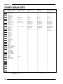
Advanced Performance Features ..................................................................................................................42
Tone Mapping......................................................................................................................................42
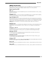
More Performance Functions...........................................................................................................................44
[DRAWBAR PRESET] Buttons................................................................................................................44
[OCTAVE +/-] Button ...........................................................................................................................45
[HOLD] Button ......................................................................................................................................46
[ORGAN TREM] Button........................................................................................................................46
[SUSTAIN] Button (BASS) ......................................................................................................................47
[MIDI] Buttons (UPPER/LOWER/BASS)................................................................................................47
v
Rodgers W-5000
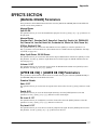
CHAPTER 4 Effects
EFFECTS Section ..................................................................................................................................................50
[MANUAL DRUMS] Button...................................................................................................................50
[UPPER DB VIB] + [LOWER DB VIB] Buttons.......................................................................................51
[DRAWBAR DISTORT] Button...............................................................................................................51
[DRAWBAR CLICK] Button ..................................................................................................................52
[CROSSFADE] Button...........................................................................................................................52
[AFTERTOUCH] Button .........................................................................................................................53
[GENERAL REVERB] Button .................................................................................................................54
[SYNTH CHORUS] Button .....................................................................................................................54
[TRANSPOSE] Button ............................................................................................................................55
[ROTARY] + [FAST/SLOW] Buttons......................................................................................................55
CHAPTER 5 General Presets
General Presets...................................................................................................................................................58
Globals ..................................................................................................................................................59
Preset Storage......................................................................................................................................60
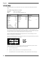
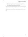
CHAPTER 6 Voicing & Controller Settings
Voicing & Controller Settings............................................................................................................................66
Keyboards............................................................................................................................................................66
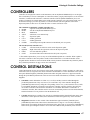
Controllers............................................................................................................................................................67
Controller Destinations ......................................................................................................................................67
Setting The Controllers .......................................................................................................................................69
Voicing …….........................................................................................................................................................70
CHAPTER 7 The Floppy Disk Drive
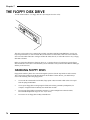
The Floppy Disk Drive .........................................................................................................................................74
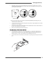
Handling Floppy Disks .........................................................................................................................74
Handling The Disk Drive ......................................................................................................................75
Formatting A Floppy Disk ...................................................................................................................76
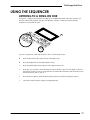
Using The Sequencer .........................................................................................................................................77
Listening To A Song On Disk...............................................................................................................77
Playback Controls ...............................................................................................................................78
Recording Your Performances.........................................................................................................................80
Storing W-5000 Data On Disk............................................................................................................................81
Registrations .........................................................................................................................................81
CHAPTER 8 Audio
The Audio System ...............................................................................................................................................86
Outputs..................................................................................................................................................86
Inputs .....................................................................................................................................................88
Speaker And Line Mixes ....................................................................................................................................88
The Speaker Mix...................................................................................................................................88
Auxiliary Inputs .....................................................................................................................................89
The Line Mix ..........................................................................................................................................90
Auxiliary Inputs .....................................................................................................................................91
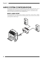
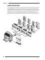
Audio System Configurations ...........................................................................................................................92
Basic Audio Setup ...............................................................................................................................92
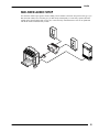
Mid-Sized Audio Setup .......................................................................................................................93
Large Audio Setup ..............................................................................................................................94
vi
User’s Guide
CHAPTER 9 Using MIDI
Using MIDI ............................................................................................................................................................96
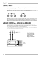
Using External Sound Modules .........................................................................................................................96
Using The W-5000 As A Sound Module ...........................................................................................................98
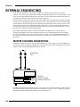
External Sequencing ........................................................................................................................................100
Master Channel Sequencing ..........................................................................................................100
Native Mode Sequencing ...............................................................................................................104
Multi-Track Recording.......................................................................................................................105
Synchronizing .....................................................................................................................................106
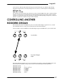
Controlling Another Rodgers Organ .............................................................................................................108
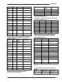
CHAPTER 10 Appendix
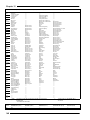
Parameter Lists ..................................................................................................................................................110
UPPER / LOWER / BASS Sections .....................................................................................................................111
[TONE] Parameters ............................................................................................................................111
[TONE 1] + [TONE 2] Parameters .....................................................................................................111
[SOLO] Parameters............................................................................................................................111
[OCTAVE +/-] Parameter..................................................................................................................113
[ORGAN TREM] Parameters.............................................................................................................113
Drawbar Parameters ([CURRENT DRAWBAR] + [DRAWBAR PRESET]) .......................................113
[MIDI] Parameters..............................................................................................................................115
[KEYBD BASS] Parameter ..................................................................................................................116
Bass [SUSTAIN] Parameters...............................................................................................................116
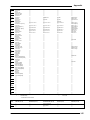
EFFECTS Section ................................................................................................................................................117
[MANUAL DRUMS] Parameters........................................................................................................117
[UPPER DB VIB] + [LOWER DB VIB] Parameters .............................................................................117
[DRAWBAR DISTORT] Parameters....................................................................................................118
[DRAWBAR CLICK] Parameter ........................................................................................................118
[CROSSFADE] Parameters................................................................................................................119
[AFTERTOUCH] Button .......................................................................................................................120
[GENERAL REVERB] Parameters ......................................................................................................120
[SYNTH CHORUS] Parameters ..........................................................................................................120
[TRANSPOSE] Parameter ..................................................................................................................121
General Controls ..............................................................................................................................................122
[ROTARY] Parameters .......................................................................................................................122
[FAST/SLOW] Parameters..................................................................................................................123
[MEMORY] (General Preset) Parameter ........................................................................................123
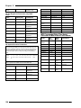
FUNCTIONS Section ..........................................................................................................................................124
[CONTROLS] + [VOICING] Parameters ..........................................................................................124
[PRESETS] Parameters........................................................................................................................127
[SEQ] Parameters...............................................................................................................................128
[AUDIO] Parameters .........................................................................................................................130
[MIDI] Parameters..............................................................................................................................133
[UTILITY] Parameters ..........................................................................................................................136
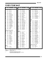
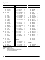
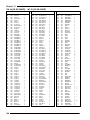
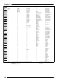
Synth Tone Map ................................................................................................................................................139
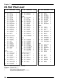
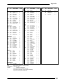
PR-300 Tone Map..............................................................................................................................................142
CM-64/MT-32 (PR-300 Subsets) ........................................................................................................144
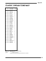
Classic Organ Tone Map ................................................................................................................................145
Synth Drum Sets.................................................................................................................................................146
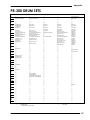
PR-300 Drum Sets ..............................................................................................................................................147
General Preset Parameters.............................................................................................................................151
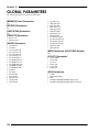
Global Parameters ...........................................................................................................................................152
Software Updates.............................................................................................................................................153
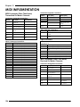
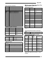
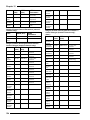
MIDI Implementation .......................................................................................................................................154
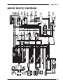
Audio Block Diagram ......................................................................................................................................160
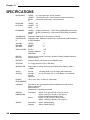
Specifications....................................................................................................................................................161
vii
Rodgers W-5000
CUSTOMER SUPPORT
The Customer Service Department of Rodgers Instruments LLC is available to answer any of your questions.
Before you call, however, please try the following steps:
•
•
•
Check your documentation
Contact your local Rodgers dealer
Call the Rodgers Field Service Department
If you are unable to resolve your problem, please feel free to call the Customer Service Department between
the hours of 7:00 AM and 5:00 PM Pacific Time, Monday through Friday (excluding holidays). Weekend
support hours are 5:00 to 9:00 PM Friday, 7:00 AM to 5:00 PM Saturday, 7:00 AM to 12:00 PM Sundays.
Call (503) 648-4181 of fax (503) 681-6530. Before you call, please have the following information in front
of you:
•
•
•
•
Model number
Serial number
Date of installation
A description of the problem and steps taken to correct it
RODGERS INSTRUMENTS LLC
1300 N.E. 25th Avenue
Hillsboro, OR 97124
Telephone: (503) 648-4181
CONVENTIONS USED IN THIS MANUAL
•
Panel buttons are indicated within square brackets. For example; Press the [UTILITY] button in the
FUNCTIONS section, and then the [+] button in the EDIT section.
•
Whenever a panel button is pressed, the LCD will instantly display relevant information; a Program
Number and name, a parameter name and setting value and so on. Generally, to navigate through the
options and to set parameter values you will:
Ê
Ë
Ì
viii
Press the relevant panel button.
Use the [NEXT] and [PREVIOUS] buttons in the EDIT section to select the desired
parameter.
Use the [+] and [-] buttons in the EDIT section to set a numeric value (e.g. 0—127) or select
an option (e.g. High, Low or Off). (Using the [++] and [--] buttons allow you to change
numeric values in large jumps.)
•
Due to space limitations, many parameter, Tone and function names are abbreviated. For example, ‘chorus’
is abbreviated as ‘Cho’. Where necessary, the abbreviations will be explained.
•
Where possible, actual LCD screens will be used in explaining the instrument’s functions. Keep in mind,
however, that screens presented by your W-5000 may differ depending on its settings.
User’s Guide
THE GENERAL MIDI (GM) SYSTEM
The General MIDI System is a universal set of specifications for sound generating devices which hasbeen
agreed upon by the Japanese MIDI Standards Committee and the American MMA (MIDI Manufacturer’s
Association). These specifications seek to allow for the creation of music data which is not limited to
equipment by a particular manufacturer or to specific models.
The GM System defines such things as the minimum number of voices that should be supported, the MIDI
messages that should be recognized, which sounds correspond to which Program Change Numbers, and the
layout of rhythm sounds on the keyboard. Thanks to these specifications, any device that is equipped with
sound sources supporting the GM System will be able to accurately reproduce GM Scores (music created
under the GM System), regardless of the manufacturer or model.
THE GS FORMAT
The GS Format is the Roland/Rodgers standardized set of specifications for Roland/Rodgers sound sources
which defines the manner in which multi-timbral sound generating units will respond to MIDI messages. The
GS Format also complies with the GM System. The GS Format, however, defines a number of additional
items. These include unique specifications for sounds, the functions available for Tone editing and effects
(e.g. chorus and reverb), and other specifications concerning the manner in which sound sources will
respond to MIDI messages.
Any device that is equipped with GS Format sound sources can faithfully reproduce GS Music Data (music
data created under the GS Format).
The W-5000 supports both the General MIDI System and the GS Format. Song data (on 3.5 inch
floppy disks) which carries either of these logos can be accurately reproduced.
STANDARD MIDI FILES (SMF)
The W-5000 can also playback Standard MIDI Files (720 Kbyte or 1.2 Mb format, 3.5 inch floppy disks)
such as the data on any commercially available SMF music disk.
ix
Rodgers W-5000
IMPORTANT NOTES
In addition to the Important Safety Instructions inside the front cover, please read and observe the following:
POWER SUPPLY
•
•
•
•
•
Before connecting the instrument to other devices, be sure the power to all units is off; this will help
prevent damage or malfunction.
Be sure the voltage in your installation meets the requirement of your instrument. Check the back panel of
your instrument for power requirements.
Do not use this instrument on the same power circuit with any device that may generate line noise; an
electric motor or variable lighting system for example.
Unplug the AC cord when the instrument will not be used for an extended period of time. When
disconnecting the AC cord, always pull on the plug itself; never pull on the cord.
Avoid damaging the power cord; do not step on it or place heavy objects on it.
PLACEMENT
•
•
Be sure to install this instrument on a very solid and stable floor or stage; its size and weight demand that
safety be an important consideration.
This device may interfere with radio and/or television reception. Avoid using this instrument in the vicinity
of such receivers. (See inside back cover for more information.)
MAINTENANCE
•
•
For everyday cleaning wipe the instrument with a soft, dry cloth. To remove stubborn dirt or stains, use a
slightly dampened cloth and a mild, non-abrasive detergent. Afterward, be sure to wipe the instrument with
a soft, dry cloth. (Be very careful not to spill any liquid into the instrument!)
Never use benzine, thinners, alcohol or solvents of any kind to avoid the possibility of discoloration and/or
deformation of plastic parts.
ADDITIONAL PRECAUTIONS
•
•
•
•
x
Take great care when moving the instrument as it is very heavy. Safety should be foremost in your mind
when you transport the unit. Proper care and a little common sense will ensure that no injuries occur and
that the instrument isn’t damaged.
Before operating the instrument in a foreign country, be sure to consult with qualified service personnel.
(Voltage incompatibility can seriously damage your instrument.)
Setting a vase, bottle or glass containing liquid on the instrument is inviting an accident to happen! Any
liquid spilled into the instrument can cause a great deal of damage or electric shock to users. To avoid such
an occurrence, don’t put any containers on the instrument. In the event that liquid is spilled into the
instrument, discontinue use immediately. Unplug the power cord from the wall and contact qualified
service personnel as soon as possible.
Contact qualified service personnel when:
•
The power cord has been damaged
•
Objects or liquids have fallen into the instrument
•
The instrument has been exposed to rain or weather damage
•
The instrument has been dropped or the enclosure has been damaged
•
The instrument does not appear to function normally
CHAPTER 1.
Introduction &
Installation
Chapter 1
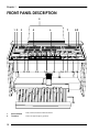
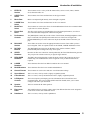
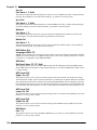
FRONT PANEL DESCRIPTION
5
1 2
3
9 10
4
11 12
6
13
14
15
7
82
16 17
18 19
20
21
22
1
Power Switch
This switch turns the W-5000 on and off.
2
Tweeters
These are high-frequency speakers.
12
Introduction & Installation
3
EFFECTS
Section
These buttons access a variety of the W-5000's effects, such as reverb, chorus, drawbar
click, aftertouch and so on.
4
UPPER Tone
Select
These buttons select Tones and functions for the Upper manual.
5
Music Rest
Music rest and panel light intensity can be changed as required.
6
LOWER Tone
Select
These buttons select Tones and functions for the Lower manual.
7
BASS Tone
Select
These buttons are used to select Tones for the Pedalboard and for the Lower manual when it
is split into two sections (Keybass).
8
Floppy Disk
Drive
The drive can be used to record and playback your keyboard performances, as well as to
store instrument data and playback commercial song data.
9
Performance
Controls
The [SPKR] knob controls the overall volume of the W-5000 (including headphones when
they're connected). The [LINE] knob controls the level of the Line Out signal. The
[Bender/Modulation] lever raises and lowers the pitch, and adds vibrato to the notes you
play.
10
BALANCE
Section
These sliders are used to create the appropriate balance between Tones which you have
layered together. There are separate sliders for the UPPER, LOWER and BASS sections.
11
ROTARY
Buttons
The [ROTARY] button activates the W-5000's rotary speaker simulator, and the
[FAST/SLOW] button changes the rotary effect speed.
12
UPPER
Drawbars
Drawbars act like tone controls for sounds produced by the Tone-Wheel/Drawbar generator.
They can provide real-time control as you play the Upper manual.
13
PERC/USER
Drawbars
The PERC (Percussion) drawbars control the attack portion of the sound (for the Upper
manual only). The USER drawbars can be assigned a variety of different functions as
required.
14
LOWER
Drawbars
These drawbars affect the Tone-Wheel sounds for the Lower manual.
15
BASS Drawbars
These drawbars affect the Lower manual and Pedalboard.
16
General Presets
These buttons are used to select and store overall instrument settings.
17
Upper Manual
This is a 61 note, velocity sensitive, lightly weighted keyboard.
18
Lower Manual
This is a 76 note, velocity and aftertouch sensitive, lightly weighted keyboard.
19
LCD/System
Controls
The LCD (Liquid Crystal Display) provides information about selected Tones and
operational status. The system controls (EDIT and FUNCTIONS) allow you to custom
configure and control your instrument.
20
Speaker
Enclosure
This box contains the W-5000's speakers.
21
Expression
Pedal
This pedal functions as a kind of volume control, but different functions can be assigned to
it. The 'kick' switches offer additional control.
22
Pedalboard
This is a 25 note, velocity sensitive pedalboard.
13
Chapter 1
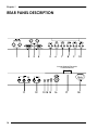
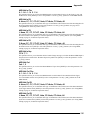
REAR PANEL DESCRIPTION
1
2
3
4
5
6
7
8
9
10
Internal Speaker/Expression
Pedal/Pedalboard
C
t
11
14
12
13 14 15
16
17
18
Introduction & Installation
1
MIXED LINE
These XLR connectors allow you to connect your W-5000 to a mixing console BALANCED
INPUT (using long cables if necessary). The signal from these connectors is a Line level mix
of the individual outputs (SYNTH, DRAWBAR and CLASSIC).
2
RODGERS
This is the standard Rodgers connector for the main individual outputs MAIN
OUTPUT(SYNTH, DRAWBAR and CLASSIC) and the MIXED LINE or SPKR OUTPUT.
It also sends a 'power on' signal to any connected amplifier(s).
3
AUX INPUT
These XLR inputs accept connection of microphones, external keyboards etc. Sensitivity and
other controls are accessible through the [AUDIO] button in the FUNCTIONS section.
4
RODGERS
This is the standard Rodgers connector for MIXED LINE Output. It also sends a
ANTIPHONAL OUTPUT 'power-on' signal to any connected amplifier(s).
5
AUX INPUT
These 1/4" inputs accept connection of microphones, sound modules, external keyboards etc.
Sensitivity and other controls are accessible through the [AUDIO] button in the
FUNCTIONS section.
6
SYNTH
OUTPUT
These 1/4" jacks provide an individual, line-level output for sounds from the Synth tone
generator. For the best results, use both jacks.
7
DRAWBAR
OUTPUT
These 1/4" jacks provide an individual, line-level output for sounds from the Tone-Wheel
generator. For the best results, especially when the Rotary simulator is active, use both jacks.
8
CLASSIC
OUTPUT
These 1/4" jacks provide an individual, line-level output for sounds from the Classic Organ
tone generator. For the best results, use both jacks.
9
MIXED SPKR
These 1/4" jacks provide a line-level output for the same signals going to the OUTPUT
internal amplifier and speakers (the Speaker mix).
10
MIXED LINE
These 1/4" jacks provide an option for connection to a mixing console (an OUTPUT optional
Line mix output).
11
MIDI 1
These MIDI ports allow you to connect your W-5000 to external MIDI devices (such as
sound modules, sequencers etc.). Control of these ports is accessed through the [MIDI]
buttons found in each section (UPPER/LOWER/BASS) and the [MIDI] button in the
FUNCTIONS section.
12
MIDI 2
Same as MIDI Port 1 without the THRU connector.
13
SW1
This 1/4" jack accepts connection of an external, switched (on/off) controller. The function
of this controller is user defined.
14
PEDAL
This 1/4" jack accepts connection of an external controller (such as an Expression pedal).
The function of such a controller is user defined.
15
ACC POWER
This is a general purpose 12v DC power outlet. It can be used to power an external piece of
equipment (like a Rodgers PR-300, for example).
16
ROTARY TONE
CABINET
This multi-pin connector is used to connect a rotary tone cabinet to your W-5000.
17
SPEAKER/
EXPRESSION
PEDAL
This multi-pin connector is used to connect the on-board speakers and Expression pedal
(both integrated into the stand) to the keyboard.
18
MAIN POWER
Connect the included AC power cord to this inlet.
15
Chapter 1
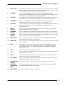
SETUP AND INSTALLATION
Because of the W-5000's size and weight, setup and installation are somewhat more involved than with a
smaller instrument. Your Rodgers dealer will very likely assist with the delivery and initial setup of your
new instrument, and this provides a good opportunity to gain first-hand experience with the process.
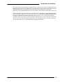
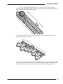
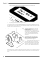
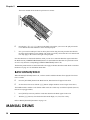
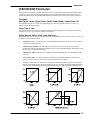
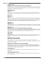
BASIC ASSEMBLY
Your Rodgers dealer may deliver your W-5000 in one piece, or it may be necessary to assemble the two
main sections; the keyboard itself and the stand. The information provided here will also be useful should
you need to disassemble the instrument for future transport.
EF
FE
CT
S
UP
PE
R
UP
PE
R
+
KR
SP
PE
-
RC
+
E
LIN
US
ER
LO
WE
R
LO
WE
R
BA
SS
BA
SS
3
4
5
6
7
8
9
NEXT
PREV
+
IOUS
-
STOP
SMF
+
+
-
REC
SMF
VOIC
PLAY
ING FUNC
TION
MIDI
S
CONT
ROLS
Ë Insert and
tighten the screws
provided
(three per side).
To disassemble
the unit, remove
these screws first.
16
Alignment pin
(both sides)
Ê Slide the locking grooves of
the brackets until they sit tightly
against the pins on the stand. To
disassemble, slightly raise the
front of the keyboard to clear the
alignment pins and then slide the
keyboard forward to disengage
the groves from the rear pins. Be
sure to disconnect the
speaker/Expression
pedal/Pedalboard cable first!
Introduction & Installation
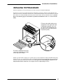
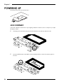
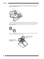
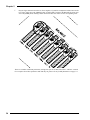
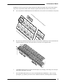
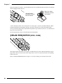
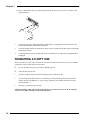
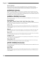
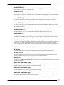
INSTALLING THE PEDALBOARD
Once the instrument is secured to the stand, it will be necessary to install the Pedalboard.
First, however, free the two pedal cables that are temporarily secured by a fastener to the underside of the
stand. (Do not remove this fastener from the base of the instrument. Before moving the W-5000, be sure that
these cables are carefully bundled (without any slack) and secured to the base using the fastener.) [NOTE:
Refer to the following page for information on pedalboard installation for the "A" version of the W5000.]
1
+
R
SPK
+
E
LIN
Ê Connect the pedal cables to the
receptacles on the right side of the
Pedalboard assembly; one is a 5pin cable for the Pedalboard) and
the other is an 8-pin cable (for the
Expression pedal).
5-pin 8i
Ë Push the pedalboard (from the
center of the heelpad) so it slides
all the way into the stand.
NOTE: If your W-5000 is sitting on a very thick carpet, it may be difficult to slide the Pedalboard into place.
If that is the case, very carefully lift one side of the instrument and rotate the adjustable feet to provide more
clearance. Then lift the other side and do the same. Take great care when making this adjustment; this
500 pound instrument could cause severe injury if it were to pinch fingers or toes!
17
Chapter 1
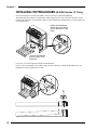
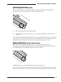
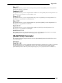
INSTALLING THE PEDALBOARD (W-5000 Version "A" Only)
Once the instrument is secured to the stand, it will be necessary to install the Pedalboard.
The Pedalboard unit contains two metal hooks which simply hook over top of the short metal bars on the
bottom of the stand. (It's very important to make sure the Pedalboard is straight while you firmly push it into
its latched position):
¶ Place the Pedalboard
against the metal hanger
pins on the bottom of the
stand.
· Push the Pedalboard
from the center of the
heelboard.
If you like, you can also adjust the height of the Pedalboard.
Note: If you are installing the unit on thick carpet, raise the console by rotating its adjustable feet so the
Pedalboard is relatively parallel to the floor:
18
Introduction & Installation
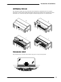
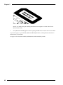
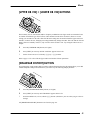
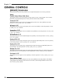
OPENING THE LID
The instrument's lid may have been locked for transit. Find the key and unlock the lid. To open the
instrument lid, simply lift the handle and fold back. When the lid is folded, push it straight back into the
instrument case. To close the lid, pull it straight out, unfold, and gently lower over the keyboards:
Ê
Ë
Ì
Í
PER
C
USE
R
LOW
ER
THE MUSIC REST
The plexiglass music rest slides easily into the deep groove on top of the keyboard:
19
Chapter 1
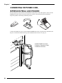
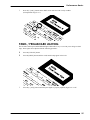
CONNECTING THE POWER CORD,
EXPRESSION PEDAL AND SPEAKERS
Be sure the [Power] switch (on the far left-hand side of the panel) is in the OFF position. Also be sure the
[SPKR] knob (main volume) (just below the Power switch) is at the minimum position and that the
Expression pedal is in the full-up (minimum) position:
Connect the included AC power cord to the MAIN POWER inlet on the rear panel of the instrument; tuck
the power cord into the channel in the leg of the stand (but don't close the cover just yet):
Ê MAIN POWER connection
Ë Speaker / Expression Pedal /
Pedalboard connection.
20
Introduction & Installation
The speakers, Expression pedal and the Pedalboard must be connected to the keyboard. Find the multi-plug
connector (which is located in the channel of the leg) and connect it to the receptacle above and to the left of
the MAIN POWER inlet. (See graphic on the previous page.) Once both the power cord and the
speaker/Expression pedal/Pedalboard cable are secure, tuck the cables inside the channel and close the cover.
Once the instrument is fully assembled, move it carefully into its final position (if it isn't already there). Be
sure the instrument is sitting on a very solid, stable floor or stage. (If necessary, stabilize the instrument by
rotating the adjustable feet on the bottom of the unit.) Remember to leave enough space behind the
instrument so that you can easily access the rear panel. Connect the power cord to a wall outlet. (Be sure the
voltage of your power outlet matches the requirement of your instrument! And never attempt to modify the
power cord; DO NOT remove the ground pin (the third prong) from the plug.)
21
Chapter 1
22
CHAPTER 2.
Performa nce
Ba sics
Chapter 2
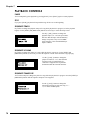
POWERING UP
Press the [Power] switch. (It's just that easy!)
LCD CONTRAST
If the LCD is difficult to read because of poor lighting conditions or whatever, there is a simple way to adjust
the display contrast:
24
Ê
Find and press the [UTILITY] button in the FUNCTIONS section (directly under the LCD):
Ë
Press the [NEXT] button (in the EDIT section) repeatedly until the words 'LCD Contrast' appear in
the LCD:
Performance Basics
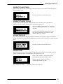
Ì
Press the [+] and [-] buttons in the EDIT section until the LCD is easily readable.
(The adjustable range is 0-9.):
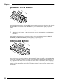
PANEL / PEDALBOARD LIGHTING
The W-5000 contains panel and Pedalboard lights which make it easy to see what you're doing on a dark
stage. These lights can be adjusted with the following procedure:
Ê
Press the [UTILITY] button.
Ë
Press the [NEXT] button until the words 'Panel Lamp' appear in the LCD:
Ì
Press the [+] and [-] buttons until the panel lights are properly adjusted; High, Low or Off.
25
Chapter 2
PERFORMANCE BASICS
The W-5000 contains three tone generators; the Drawbar/Tone-Wheel generator (for contemporary organ
sounds), the Classic Organ generator (for classical and church organ sounds), and the Synth generator (for
synthesized instrument and percussion sounds). The following sections describe how to select and play
sounds from these three generators. (If you've worked through the Quick Start guide, you'll already be
familiar with these procedures.)
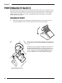
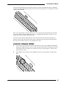
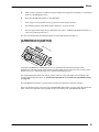
DRAWBAR TONES
Ê
While seated comfortably (on the handsome and functional bench!), raise the volume a little by
rotating the [SPKR] knob clockwise and by depressing the Expression pedal slightly.
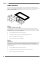
Ë Play a few notes on the Upper manual (the top keyboard) and
set an appropriate volume with the [SPKR] knob and Expression
pedal.
Headphones can also be used; the headphone jack is located just
below the [Bender/Modulation] lever. Note that connecting
headphones to this jack will cut off the internal and any external
speakers. Take great care when using headphones however;
excessive volume levels can easily damage your hearing!
[Bender/Modulation] lever
26
Performance Basics
Ì
Find the [CURRENT DRAWBAR] button in the group of buttons marked UPPER; the
button's red LED (Light Emitting Diode) should be lit. (When a [CURRENT DRAWBAR] button is
lit, the W-5000's Tone-Wheel generator is active.)
UP
PE
R
Í
While playing the Upper manual with your right hand, move some of the UPPER drawbars (the
sliders with all the numbers on them):
As you play, you'll instantly hear that each drawbar affects a different range of the harmonic content
of the sound. You'll discover that each one controls different frequency ranges, like sophisticated tone
controls. Once you get a little experience you'll be able to quickly create the sound you want.
27
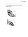
Chapter 2
Î
Just to the right of the nine UPPER drawbars are two PERC (Percussion) drawbars. Try pushing and
pulling these drawbars and you'll notice that they affect the attack or initial portion of the sound,
making it a little 'harder' or 'softer'.
Ï
To add to the fun, find the [ROTARY] button (located on the vertical panel just under the Upper
manual). When this button is lit, the W-5000's rotary speaker simulator is active. (This simulates the
effect of real rotary speakers such as the famed Leslie.) To change the rotary speed, press the
[FAST/SLOW] button.
However, you can also change the speed using the right 'kick' switch on the Expression pedal (just
give it a little tap with the right side of your foot!):
The right foot (or ‘kick’)
switch controls rotary
speed.
The left foot (or ‘kick’)
switch controls sustain of
Synth Tones.
28
Performance Basics
All of the controls and functions described here (with the exception of the PERC drawbars) are duplicated
for the Lower manual (the bottom keyboard). All of the relevant controls for the Lower manual are (cleverly
enough) marked LOWER!
There are several parameters (settings) which you can set to customize the W-5000's drawbar sounds and
rotary effect. Refer to 'Drawbar Parameters' on page 113, and '[ROTARY] Parameters' on page 122 for a
complete list of these parameters and what they do.
Of course, the Drawbar/Tone-Wheel generator is but one of three in the W-5000. This instrument also
contains a Classic Organ tone generator which creates sounds ideally suited to classical and church music.
The next section will show you how to select and play these Tones.
CLASSIC ORGAN TONES
Ê
To access the Classic Organ Tones for the Upper manual, first press the [CURRENT DRAWBAR]
button in the UPPER Tone select section; be sure the button's LED is dark. (It's important to turn the
Tone-Wheel generator off, otherwise its sounds will be layered - played together - with the Classic
Organ Tones you select.)
Ë
Press [ORGAN 1] (for example) in the UPPER Tone select section. The button's red LED should
light:
UP
PE
R
29
Chapter 2
Depending on which Tone has been assigned to that button (which you'll learn how to do), the LCD
will read something like:
This indicates a Program Number ('1' in this case), a Bank Number ('0'), and a name ('Gedackt'). (Note
that much of the terminology used with the W-5000's Classic Organ Tones comes from traditional
pipe organs.)
Play the Upper manual to hear the sound you have selected.
Ì
To select different Classic Organ Tones (Program Numbers), press the [+] button in the EDIT section.
Pressing the [+] button will advance through the Program Numbers and pressing the [-] button
reselects the previous Program Number.
Í
Try some of the other organ Tones under the [ORGAN 2], [ORGAN 3] and [ORGAN 4] buttons if
you like. Again, you can select additional Tones using the [+] and [-] buttons in the EDIT section.
(Don't be concerned about selecting some of the same sounds you found under the [ORGAN 1] button
- we'll explain what's going on in due time!)
UP
PE
R
30
Performance Basics
NOTE: If you've already tried, you've discovered that the drawbars will not affect the Classic Organ Tones.
The Classic Organ and Drawbar/Tone-Wheel generators are independent of one another. The drawbars are
active ONLY when a [CURRENT DRAWBAR] button is lit.
Finally, we come to the last Tone generator in the W-5000, the generator that produces...
SYNTH TONES
Ê
To access the W-5000's Synth Tones for the Upper manual, first be sure the [CURRENT
DRAWBAR] button in the UPPER Tone select section is dark. (Again, for now you probably won't
want the drawbar sounds to be heard with the Synth Tones you select.)
UP
PE
R
Ë
Press [PIANO 1] (for example) in the UPPER Tone select section. The button's red LED should light .
UP
PE
R
31
Chapter 2
Again, depending on what Tone has been assigned to that button, the LCD might read:
Ì
Play the Upper manual and you'll hear a piano sound.
You might also want to try moving the [Bender/Modulation] lever (just below the [SPKR] knob) while you
play. Note that this lever affects all but a few of the Synth Tones available; a simple trial will tell you which.
(Drawbar Tones are unaffected by this lever.)
+
The [Bender/Modulation] lever is one of the
W-5000 controllers.
Pushing the [Bender/Modulation lever to the
right raises the pitch (+), pushing it to the left
lowers the pitch (-), and pushing it forward adds
a vibrato effect. Pitch bend and modulation
effects work best with synthesizer-type tones.
Experiment!
Pitch bending sounds a little strange when
applied to a fixed-interval instrument like a
piano, so just use your best judgement when
deciding which sounds to apply it to.
Í
To select other piano sounds, press the [+]
button in the EDIT section. As you press this
button you'll step through these sounds, starting
with Piano 1: Piano 2, Piano 3, Honky-Tonk. E.
Piano 1, E. Piano 2, Harpsichord and Clavinet.
NOTE: Don't press the [+] button any further at this point as the 'Tone Map' - the way sounds are organized may seem a little confusing at first. Eventually you'd call up sounds that aren't even remotely related to the
piano!
32
Performance Basics
The idea behind the W-5000's structure is that you're able to assign any Tone to any Tone button. So, for
example, if you have three favorite piano sounds, you can easily assign each of them to one of the three
Piano buttons ([PIANO 1], [PIANO 2] or [PIANO 3]) in a Tone select section. By doing this you'll be able
to instantly recall your favorite piano sounds without having to dig through layers of Program and Bank
Numbers. For a more detailed explanation of the W-5000's sound organization and how to assign Tones to
Tone buttons, please refer to 'Tone Mapping' on page 42.
LAYERING TONES
Further increasing the W-5000's versatility is the ability to layer Tones, that is, having two Tones sound
together.
So far we have been dealing with Tone 1 sounds only. When the [TONE 1/TONE 2] button (in any Tone
select section) is red, you'll be selecting Tone 1 sounds; any Tone button you press will light with a red LED.
Note that you can only select a single Tone 1 sound at a time (pressing another Tone select button will
replace your previous selection) .
UP
PE
R
If, however, you press the [TONE 1/TONE 2] button again so its green LED lights, you'll be able to choose a
second Tone to layer with the Tone 1 sound you've selected. Follow this example and you'll see what we
mean.
In the UPPER Tone select section:
Ê
Press the [TONE 1/TONE 2] button so its red LED lights.
Ë
Press the desired Tone select button (its red LED should light).
Ì
Press the [TONE 1/TONE 2] button again so its green LED lights.
Í
Press another Tone select button (its green LED should light).
You'll now have two active Tone buttons; one lit with a red LED (Tone 1) and the other lit with a green LED
(Tone 2). (Note that simply pressing two Tone buttons simultaneously will achieve the same result.)
33
Chapter 2
Î
Play the Upper manual to hear the two Tones together. If you'd like to adjust the balance between the
two Tones, simply move the UPPER [TONE 1] and [TONE 2] sliders in the BALANCE section (just
above the [SPKR] knob). Pulling a slider down will reduce the volume for the corresponding Tone.
There are a number of different parameters (settings) that you can set that affect Tone 1 and Tone 2 sounds.
For a complete list of these parameters and what they do, please refer to '[TONE] Parameters' on page 111.
34
Performance Basics
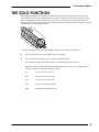
THE SOLO FUNCTION
The UPPER and LOWER sections of the W-5000 each contain a [SOLO] button. When this function is
active (the button LED is lit), an additional Tone is enabled, which can be restricted to following a single
note, or arpeggiating a chord. In effect this gives you three Tones playable from each manual. Balance
among the three Tones of either manual can be adjusted using the corresponding sliders ([TONE 1], [TONE
2] and [SOLO]) in the BALANCE section.
UP
PE
R
To use the Solo function (for either the UPPER or LOWER section), follow this procedure:
Ê
Press the [SOLO] button in the UPPER section (for example).
Ë
Select a Solo Tone using the [+] and [-] buttons in the EDIT section.
Ì
Press the [NEXT] button repeatedly until the words 'Solo Mode' appear in the LCD.
Í
With the [+] and [-] buttons, select the desired Solo mode: Poly, First, Last, Low, High, Sequence,
Up, Down, Up & Down, Wander, Random or Chord.
Poly
: All notes use the Solo Tone
First
: First note uses the Solo Tone
Last
: Last note uses the Solo Tone
Low
: Lowest note uses the Solo Tone
High
: Highest note uses the Solo Tone
35
Chapter 2
Arpeggio Modes
The seven Arpeggio modes are an extension of the W-5000's Solo function. The delay time between
the arpeggiated notes or chords is determined by the Vibrato rate. Arpeggio sequences may also be
'latched' using the Sustain pedal. These Arpeggio modes are:
Sequence
: Notes played are played back, one at a time, in the same sequence (order) they
were played in.
Up
: Notes are played back, one at a time, in ascending order.
Down
: Notes are played back, one at a time, in descending order.
Up & Down
: Notes are played back, one at a time, in alternating ascending and descending
order.
Wander
: This mode is similar to the 'Up & Down' mode except that it changes randomly.
Random
: All notes are played one at a time but in a random order.
Chord
: The Arpeggio sequence is based upon a repeated (or looped) four-beat measure in
which all the notes are quantized. This simply means that all the notes which fall
within the first beat of the bar will be timed to play precisely where they should.
The same applies to all the notes falling within the second, third and fourth beats.
The delay time between the beats depends upon the value set for the Vibrato rate.
Arpeggio Latching
In the Arpeggio modes the sustain function no longer sustains notes, but instead 'latches' them into the
Arpeggiator. This allows you to play longer arpeggios than you can reach at one time.
As you've seen in the LCD, the Solo function also contains a number of other parameters which you can set
(including the note range over which the Solo Tone is heard). See '[SOLO] Parameters' on page 112 for a
complete list and description of these parameters.
36
Performance Basics
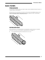
BASS TONES
PEDALBOARD
No serious players' instrument of this type would be complete without a Pedalboard! And the W-5000's is as
versatile as the rest of the instrument.
The BASS Tone select section allows you to select a variety of Tones for the Pedalboard. Again, you can
layer Tones (using the [TONE 1/TONE 2] button) and create the appropriate balance using the BASS
[TONE 1] and [TONE 2] sliders in the BALANCE section.
KEYBOARD BASS
One last option allows you to split (divide) the Lower manual into two parts, allowing you to play Bass
Tones in the section to the left of the split point, and standard Tones to the right of it.
Ê
Press the [KEYBD BASS] button in the BASS Tone select section :
37
Chapter 2
The Lower manual will be divided or split into two sections:
Ë
Pressing the [+]/[-] or [++]/[--] buttons in the EDIT section allow you to move the split point on the
Lower manual. Use these buttons to set the desired split point.
Ì
Now you can select and layer Tones for the keybass section using the same procedure described for
the Upper and (complete) Lower manuals. The Tone(s) previously selected for the Lower manual will
now only apply to the section to the right of the split point.
Note also that there are four BASS drawbars which you can use to control the Drawbar organ sound when
the BASS section [CURRENT DRAWBAR] button is lit. (Remember that drawbars for a particular section
are active only when the corresponding [CURRENT DRAWBAR] button is lit.)
The drawbar parameters that we mentioned earlier also apply to the Bass drawbar sounds. Refer to 'Drawbar
Parameters' on page 113 for information about them.
BASS SUSTAIN/SOLO
When the BASS [SUSTAIN] button is lit, a release sustain is added to the Bass Tones played. This release
time is variable:
Ê
Press the [SUSTAIN] button in the BASS section; 'Bass Sustain' will appear in the LCD.
Ë
Set the release time (0-10) with the [+]/[-] buttons. (Higher numbers create a longer release time.)
The Pedalboard also contains a Solo function which works in a similar way as with the keyboards (however,
there are no Arpeggio modes):
Ì
Press [NEXT] as necessary until the words 'Bass Sustain Solo Mode' appear in the LCD.
Í
With the [+]/[-] buttons, select the desired Solo mode: High, Low, Last, First or Poly.
Refer to 'BASS [SUSTAIN] Parameters' on page 116.
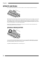
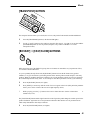
MANUAL DRUMS
38
Performance Basics
In addition to all of its great Classic Organ, Drawbar/Tone-Wheel and Synth Tones, the W-5000 contains a
wide variety of percussion sounds. These sounds are organized into Drum Sets and are easily selected.
Ê
Press the [MANUAL DRUMS] button in the EFFECTS section (on the far left-hand side of the panel)
:
Ë
Play the Lower manual (towards the left) and you will hear that a different percussion sound has been
assigned to almost every key. (Note that some keys do not have an assigned sound.)
2
Ì
(in the EDIT section) four or five times until the display stops changing. This simply moves the split
point farther and farther to the right.
Í
Press the [NEXT] button until you see the words 'Manual Drums Standard Set 1' in the LCD. By
pressing the [+]/[-] buttons you can now select a different Drum Set (containing different sounds):
39
Chapter 2
NOTE: As a default setting, the USER [2] drawbar has been assigned as a volume control for the
Manual Drum sounds.
Î
Press [MANUAL DRUMS] again to return to playing standard Tones across the entire Lower manual.
If you refer to page 117 you'll find the '[MANUAL DRUMS] Parameters'. All the parameters that relate to
Manual Drums are listed there.
See page 146 for a list of the available Synth Drum Sets and the sounds they contain.
40
CHAPTER 3.
Adva nced
Performa nce
Fea tures
Chapter 3
ADVANCED PERFORMANCE FEATURES
Now that you've had a little hands-on experience, you should have a good understanding of the W-5000's
basic operation. In this chapter, however, we'll move on to describe some of the instrument's more advanced
features.
TONE MAPPING
The W-5000 contains three 'Tone Maps' (collections or arrangements of sounds): Organ, Synth and PR-300.
The Organ Tone map contains the Classic Organ Tones. You select this map automatically whenever you
press one of the Organ buttons. The Synth map contains most of the other instrument sounds (Pianos, Guitars
etc.) and the PR-300 map contains the sounds found in Rodgers' PR-300 sequencer/sound module. (There is
a fair degree of overlap of sounds in the Synth and
PR-300 Tone maps and this has to do with compatibility with other Rodgers and Roland products should
they be used in conjunction with the W-5000.) (The sounds in the three Tone maps are presented starting on
page 142.)
As described earlier in the section about Synth Tones, it is possible to assign any Tone in the W-5000 to any
Tone button on the front panel. So although every button comes with a pre-assigned Tone, you can, if you
like, custom configure the entire instrument to your liking!
The Tone select buttons are marked with general instrument categories like Piano, Organ and Guitar for
example. If you look at the UPPER Tone select section for a moment, you'll notice that there are three Piano
buttons (for example). Well, the W-5000 contains some 30 different piano-type sounds, including acoustic
and electric varieties, and even harpsichord and clavinet! How do you go about selecting those different
sounds and how do you assign them to the various buttons?! Good questions! Let's take a look.
TONE SELECTION AND MAPPING
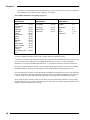
In simple terms, within each Tone Map (Organ, Synth and PR-300) sounds in the W-5000 are organized by
Program Number (abbreviated as 'Prg' in the LCD) and Bank Number ('Bnk'):
42
Advanced Performance Features
Each Program Number represents a basic instrument sound and the Bank Number represents a variation of
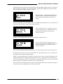
that basic sound. For example, if you press the [PIANO 1] button in the UPPER section (which normally
selects the PR-300 Tone Map), the display will read:
The Tone ‘Piano 1’ is found at Program Number 1
and Bank Number 0 in the PR-300 Tone map. This
Tone is assigned to the [PIANO 1] button at the
factory.
If you press [NEXT] (to move the underline cursor to the Bank field) and then press [+], the Tone 'Piano 1w'
will appear. This is the first variation of the basic Piano sound:
The Tone ‘Piano 1w’ (the ‘w’ stands for ‘warm’) is
found at Program Number 1 and Bank Number 8 in
the PR-300 Tone map. This Tone is the first
variation of ‘Piano 1’.
Press the [+] button again and the Tone 'Piano 1d' will appear (Bank Number 16):
The Tone ‘Piano 1d’ (the ‘d’ stands for ‘dark’) is
found at Program Number 1 and Bank Number 16 in
the PR-300 Tone map. This Tone is the second
variation of ‘Piano 1’.
Don't worry that the Bank Numbers don't increase by one each time, that's just the way this system works!
So basically, to select any Tone you see in a particular Tone map (starting on page 139), you simply select
the Program Number and then the Bank Number.
NOTE: To switch among the three Tone maps, you simply press any Tone select button and then press the
[NEXT] button until the word 'Map' appears in the LCD. Use the [+] and [-] buttons to select the desired
Tone map: Synth, PR-300 or Organ. The Synth map is normally selected whenever you press a Tone button
and the Organ map is normally selected when you press an Organ button.
Note also that when switching between Tone maps, the Prg and Bnk numbers may automatically change to
reflect the closest Prg or Bnk Number of the newly selected map.
43
Chapter 3
OK, suppose you want to assign the Tone 'Hyper Alto' to the [PIANO 2] button in the UPPER Tone select
section:
Ê
Press the [PIANO 2] button in the UPPER section.
Ë
Select the Tone 'Hyper Alto' (Program Number 66, Bank Number 8 in the Synth Tone map).
Do this by pressing the [++] button (which moves you in jumps of eight) until you reach Program
Number 65, then increase the Program Number to 66 by pressing the [+] button. Now press [NEXT]
to move the cursor to the Bank field. Press [+] and Bank 8 is selected. (Again, don't worry that the
Bank numbers don't increase in simple numeric order, it's just the way things are!)
Ì
That's it! 'Hyper Alto' is now assigned to the [PIANO 2] button. Press any other Tone button in the
UPPER section, play a few notes, then go back to [PIANO 2]; 'Hyper Alto' will be there! (Note,
however, that unless you save your custom Tone map by storing it in a Preset (see page 58), the
default (factory) Tone map will be in effect whenever you power up the instrument.)
NOTE: You probably wouldn't want to put a saxophone sound under a Piano button (it would likely
be better to put it under one of the Reed buttons), but the flexibility is there.
By assigning the Tones you use most often to specific Tone buttons, you'll be able to instantly recall them
without having to dig through layers of Program and Bank Numbers. In this way, you can configure the
entire instrument to suit your particular tastes and requirements.
MORE PERFORMANCE FUNCTIONS
In addition to the Tone select buttons, each of the UPPER, LOWER and BASS sections also contain a
number of performance-related controls.
[DRAWBAR PRESET] BUTTONS (UPPER; LOWER; BASS)
UP
PE
R
Each section (UPPER, LOWER and BASS) contains a [CURRENT DRAWBAR] button - a button which
activates the Tone-Wheel generator for the corresponding section. When this button is lit, you can use the
drawbars to create real-time changes in the sound produced.
Well suppose you come across a killer sound that you don't want to lose. What do you do? You could write
down the drawbar settings but that would be impractical. Instead, you can instantly save that current setting
using a [DRAWBAR PRESET] button. (Note that the UPPER and LOWER sections each have three
[DRAWBAR PRESET] buttons ([A], [B] and [C]), and the BASS section has just one.) Try the following
example.
44
Advanced Performance Features
In the UPPER section (be sure any Tone select buttons are turned off):
Ê
Press the [CURRENT DRAWBAR] button.
Ë
Play the Upper manual and adjust the UPPER and PERC drawbars to your liking.
Ì
Press and hold [DRAWBAR PRESET A] and then press the [CURRENT DRAWBAR] button.
All of the current drawbar settings are now stored under the [DRAWBAR PRESET A] button and can be
recalled at any time. Note that when [DRAWBAR PRESET A] is active the drawbars will not affect the
sound; the drawbars are active ONLY when the [CURRENT DRAWBAR] button is lit. You can, of course,
also create and store different settings for [DRAWBAR PRESET B] and [DRAWBAR PRESET C].
You can also copy the current or active drawbar settings from one manual to a Preset button of the other: Be
sure the destination Preset button is off, then press and hold that Preset button and then tap the desired
[CURRENT DRAWBAR] button from the source manual.
Several parameters (including drawbar click time and level) can be accessed whenever a [CURRENT
DRAWBAR] or [DRAWBAR PRESET] button is pressed. These parameters are listed and explained on
page 113. (When [CURRENT DRAWBAR] settings are 'captured' as described above, the other [CURRENT
DRAWBAR] parameters are also copied into the preset. These parameters can be edited individually for
each preset.) General on/off control of click sounds is controlled by the [DRAWBAR CLICK] button in the
EFFECTS section.
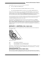
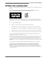
[OCTAVE +/-] BUTTON (UPPER; LOWER; BASS)
Each section contains a [+/- OCTAVE] button which is used to shift the pitch of the selected keyboard an
octave higher or lower:
UP
PE
R
When the button LED is...
Dark
Red
Green
: the keyboard is at normal pitch
: the keyboard pitch is one octave higher than normal
: the keyboard pitch is one octave lower than normal
NOTE: The [+/- OCTAVE] buttons do not affect Drawbar Tones. They do, however, affect Tone 1, Tone 2
and Solo Tones, as well as Classic Organ Tones and MIDI output. Notes sustained when a [+/- OCTAVE]
button is pressed are not affected either.
[HOLD] BUTTON (UPPER; LOWER; BASS)
Each section of the W-5000 has a [HOLD] button. Quite simply, whenever this button is lit in a particular
section, notes played on the corresponding keyboard will be sustained* whenever the left 'kick' switch on the
45
Chapter 3
Expression pedal is activated (i.e. moved and held to the left). The [HOLD] button also allows note latching
when in arpeggio modes (page 36).
Left ‘kick’ switch
(footswitch) controls
the Hold function.
Right ‘kick’ switch
(footswitch) controls
rotary speed.
* Some instrument sounds - like acoustic piano or acoustic guitar - cannot be sustained indefinitely. When
using the Hold function with sounds of this type, the notes will sustain for a short time and then decay
slowly. Sounds like Strings, Brass instruments and synthesizer-type sounds can, however, be sustained for as
long as the footswitch is held.
Note also that Drawbar Tones are not affected by the Hold function.
[ORGAN TREM] BUTTON (UPPER; LOWER)
The Organ Tremolo effect adds a low frequency oscillation (LFO) to pitch, volume and filtering of Classic
Organ Tones. This is a kind of vibrato effect. Organ Trem is active for a keyboard when the corresponding
button's LED is lit.
Refer to '[ORGAN TREM] Parameters' on page 113 for a list of settings you can make for this effect.
46
Advanced Performance Features
[SUSTAIN] BUTTON (BASS)
When on (the button LED is lit), this function adds a release time to the Drawbar and Synth Bass notes
played. This function affects both the Keybass section and Pedalboard Tones.
Ê
Press the [SUSTAIN] button (in the BASS section).
Ë
Set the release time (0-10) with the [++]/[--] or [+]/[-] buttons. (Higher numbers produce a longer
sustain time.)
Note: If the Solo Mode (under the [SUSTAIN] button) is set to something other than 'Poly', new notes played
will 'squelch' (i.e. cut off or clip) the previous notes. So the combination of a non-zero Sustain value and a
monophonic Solo mode setting allow you to mimic the old style 'walking' organ bass sounds.
[MIDI] BUTTONS (UPPER; LOWER; BASS)
Each section contains a [MIDI] button which allows you to access the MIDI parameters for the
corresponding section. Refer to 'Using MIDI' (page 96) for further information. (This button is somewhat
like the 'MIDI Coupler' in other Rodgers Organs, but is much more flexible.)
All MIDI parameters are listed under '[MIDI] Parameters' starting on page 115.
Note: The three MIDI 'layers' are selectable under the [VOICING] and [CONTROLS] buttons, so the MIDI
outputs can act like any other layer. This provides extreme flexibility in controlling external sound modules.
47
Chapter 3
48
CHAPTER 4.
Effects
Chapter 4
EFFECTS SECTION
The 10 buttons in the EFFECTS section control a number of effects and special performance functions.
When an EFFECTS section button is pressed, the LCD will instantly show the current setting or value for the
first parameter of that effect. When the value is displayed, the [+] and [-] buttons in the EDIT section can be
used to change the value or setting. Keep in mind that some effects may have several parameters. Generally,
these additional parameters can be selected by pressing the [NEXT] and [PREVIOUS] buttons. Then you can
use the [+] and [-] buttons to set the value for that parameter.
NOTE: Even if a parameter for a particular effect is properly set, that effect will not be heard unless the
corresponding EFFECTS button is currently lit.
[MANUAL DRUMS] BUTTON
As we've already discussed the Manual Drums function, we won't repeat that information here. To refresh
your memory, you may want to refer back to page 39. And if you'd like to see a list of the available Drum
Sets and the sounds they contain, please refer to page 146.
All '[MANUAL DRUMS] Parameters' are listed on page 117.
50
Effects
[UPPER DB VIB] + [LOWER DB VIB] BUTTONS
These buttons (one for each manual) add low frequency modulation to the Upper and Lower Drawbar Tones
to simulate Tone-Wheel type vibrato effects. (These buttons turn the effect on and off.) There are several
settings you can make for this effect. Note that the same setting must be made for both the Upper and Lower
manuals. As that is the case, changing one setting automatically changes the other. Note also that the Vib and
Rotary effects are mutually exclusive; only one effect can be used at a time. Try setting the vibrato rate as a
sample:
Ê
Press the [UPPER DB VIB] button (so it lights).
Ë
Press [NEXT] as necessary until the word 'Rate' appears in the LCD.
Ì
Set the vibrato rate (0-127) with the [+]/[-] (or [++]/[--]) buttons.
Refer to page 117 for a list of all the Upper and Lower Drawbar Vibrato parameters.
[DRAWBAR DISTORT] BUTTON
No contemporary organ sound would be complete without distortion! Pressing this button allows you to add
simulated amplifier and speaker distortion to your sound. Try the following sample parameter:
Ê
Press the [DRAWBAR DISTORT] button (so it lights).
Ë
Press [NEXT] as necessary until 'Threshold N' appears in the LCD.
Ì
Set the threshold level (-10-10) with the [+]/[-] buttons. (Hold on to your ears when you get to the '10'
setting!)
All '[DRAWBAR DISTORT] Parameters' are listed on page 118.
51
Chapter 4
[DRAWBAR CLICK] BUTTON
One of the things that made those old Tone-Wheel organs sound so unique was the keyswitch noise. Pressing
the [DRAWBAR CLICK] button on the W-5000 allows you to add that distinctive quality to your own
sound:
Ê
Press the [DRAWBAR CLICK] button (so the LED lights).
Ë
With the [+] and [-] buttons, set the 'Filt Cutoff' point (0-127). (This controls the overall brightness of
the effect.)
Other Drawbar parameters (such as click level and time) can be accessed by pressing any [CURRENT
DRAWBAR] or [DRAWBAR PRESET] button ([A], [B] or [C]). See page 113.
[CROSSFADE] BUTTON
The Crossfade function allows you to use what we call 'velocity-controlled mixing'. What this means is that
when two Tones are selected for a keyboard, differing amounts of those two sounds can be heard depending
on how hard you play the keyboard. For example, in the 'Normal' mode (automatically selected at power up),
as you play harder both Tones increase in volume at the same rate. In the 'Switch' mode, however, playing
softly allows you to hear only Tone 1. As you play harder and harder you'll reach a point at which the Tone 1
sound is no longer heard and only the Tone 2 sound is heard. Follow this procedure to try out the Velocity
Switch mode:
52
Effects
Ê
Select a Tone 1 and Tone 2 sound for the Upper manual. (Selecting Tones which have a very different
character will highlight the effect.)
Ë
Press the [CROSSFADE] button (so the LED lights).
Ì
Select 'Upper' as the keyboard. (Use the [+] button if it isn't already selected.)
Í
Press [NEXT] until the word 'Mode' appears and press [+] to select 'Switch'.
Î
Play the Upper manual softly and you should only hear Tone 1. Gradually play harder and harder. At
some point you'll only hear Tone 2.
The other Crossfade modes and related parameters are listed and explained on page 119.
[AFTERTOUCH] BUTTON
Aftertouch is modulation (or change) that occurs to a sound after the sound has been played. This
modulation is created by playing a note and then exerting further pressure on the key once it's down (at the
bottom of its travel). Only the W-5000's Lower manual is aftertouch sensitive.
The Aftertouch depth for Pitch, TVF Cutoff, Volume, LFO rate, LFO pitch depth, LFO TVF depth, LFO
TVA depth and expression can be set. All aftertouch parameters are set under the [CONTROLS] menu
(see page 69).
The [AFTERTOUCH] button is a general on/off switch for the aftertouch continuous controller.
Note: The aftertouch signal is also sent to the [CROSSFADE] button where it can be used in the '2nd Touch'
mode. In this case, aftertouch works regardless of the on/off setting of the [AFTERTOUCH] button.
53
Chapter 4
[GENERAL REVERB] BUTTON
Reverb is a digital effect which creates the illusion that you're playing in spaces of different sizes (like a
concert hall or room, for example). That is, the sound decays naturally over time. Pressing the [GENERAL
REVERB] button allows you to select the reverb time (which applies to all Tones):
Ê
Press the [GENERAL REVERB] button (so the button LED lights).
Ë
Press [NEXT] as necessary to select the 'Time' parameter.
Ì
With the [+] and [-] buttons set the Reverb Time (0-127). Higher numbers result in a longer reverb
time.
There are several additional parameters that affect Reverb and these are listed on page 120.
[SYNTH CHORUS] BUTTON
Chorus is a digital effect which makes one instrument sound like several; as if they were playing in unison.
The [SYNTH CHORUS] button allows you to set the amount of chorus for Synth Tones:
Ê
Press the [SYNTH CHORUS] button (so its LED lights).
Ë
Press [NEXT] as necessary to select the 'Level' parameter.
Ì
Use the [+] and [-] (or [++]/[--]) buttons to set the Chorus Level (0-127). (Note that the other
parameters must be set properly before any effect will be heard.)
All the Chorus parameters are listed on page 120.
54
Effects
[TRANSPOSE] BUTTON
The transpose function allows you to shift (raise or lower) the pitch of both manuals and the Pedalboard:
Ê
Press the [TRANSPOSE] button (so the button LED lights).
Ë
Use the [+] and [-] buttons to raise and lower the pitch. The range is: C#-1-B0. (You can also hold the
[TRANSPOSE] button (in the 'on' position) and press a key relative to Middle 'C' to set the
transposition value.)
[ROTARY] + [FAST/SLOW] BUTTONS
ROT
ARY
FAS
T
SLO
W
While not strictly part of the EFFECTS group, these two buttons are nonetheless very important as effects,
so we'll talk a bit about them here.
As you've probably already discovered, the [ROTARY] button activates the W-5000's rotary speaker
simulator; a very special software system that generates those amazing vibrato sounds unique to real rotary
speakers. What you probably don't know is that there are several parameters which you can set to customize
the sound and speed of the rotary effect. As an example of what these parameters can do, try the following:
Ê
Press the [ROTARY] button (so it lights).
Ë
Press [NEXT] (as necessary) until the words 'Tw Level' appear in the LCD. (This particular parameter
allows you to set the volume of the tweeter or high frequency driver.)
Ì
While you play, press the [++] button so the tweeter volume increases. Set the volume where
sounds best (0-127).
it
The [FAST/SLOW] button and the right footswitch on the Expression pedal change the rotation speed of the
speaker simulation. Again there are several parameters that affect this function so we'll just mention one
which really demonstrates what they're all about.
Ê
Press the [FAST/SLOW] button (so it lights).
55
Chapter 4
Ë
Press [NEXT] (as necessary) until the words 'Tw Rise Time' appear. (This parameter allows you to set
the time it takes for the tweeter rotation speed to reach maximum from its minimum speed. Parameters
for setting the minimum and maximum speeds are also available.)
Ì
Set the rise time (0-9) with the [+]/[-] buttons. (Higher numbers create a longer rise time.)
Now as you press the [FAST/SLOW] button (or activate the right footswitch on the Expression pedal)
the tweeter will speed up at the new rate you have set.
All of the Rotary parameters and their functions are listed on page 122. Fast/Slow parameters are listed on
page 123.
56
CHAPTER 5.
Genera l
Presets
Chapter 5
GENERAL PRESETS
Along the front edge of the instrument - between the Upper and Lower manuals - is a series of 11 buttons
(ignore [ROTARY] and [FAST/SLOW] for the moment). There are eight General Preset buttons ([1]-[8];
also called 'Pistons'), a [SET] button, a [MEMORY] button and a [CANCEL] button:
Each button allows you to store (and later instantly recall) all the panel settings that define the sound of the
instrument (minus a few global settings, described later). This collection of settings, called a 'registration',
includes Tone assignments, effect settings and function settings. (See page 150 for a complete list of the
parameter settings you can store in a General Preset.)
A total of seventeen registrations can be stored in the W-5000's memory. The eight numbered buttons
(pistons) can each contain a different registration, while the [MEMORY] button functions as a switch to
alternate between two different banks (when this button is lit, the second bank is active). One additional
registration can be stored under the [CANCEL] button. (Normally the [CANCEL] button is used to store a
'silent' registration, used to mute the instrument, or a default registration, automatically selected when the
instrument is turned on.)
In order for registrations to be retained in memory when the instrument is turned off, they are also stored in
'files' in the W-5000's internal, non-volatile memory. As we will see later, these files can also be stored on
floppy disk, greatly expanding the flexibility of your instrument.
The W-5000 comes with seventeen preset registrations in its non-volatile memory. When the instrument is
turned on, these registrations are automatically loaded and can be selected with the numbered buttons. You
can, of course, modify these registrations in whatever manner you wish and then reassign them to the
numbered buttons. This is accomplished using the [SET] button.
To store a registration:
58
General Presets
Ê
Make all the necessary panel settings (Tone assignments, effects settings and function settings) until
everything sounds just right.
Ë
Be sure the [MEMORY] button is on or off, depending on which bank of registrations you wish to
work with. (When lit, the second memory bank is active.)
Ì
Hold the [SET] button and then press the General Preset button ([1]-[8]) you want to use.
Note: If the 'Memory Lock' parameter is 'On', the Preset memories are protected and saving a registration
will not be possible. See [PRESETS] 'Memory Lock' (page 128) for more information.
Instantly your registration is stored under the General Preset button you pressed and can be recalled at any
time. These registrations will remain in memory (even after you power down) until you change them. By
creating and storing a series of registrations for different performance needs, you can easily set up the
instrument for your next song or set; live performances become much simpler!
(You can also assign a registration to the [CANCEL] button if you like. Simply hold the [SET] button and
press [CANCEL] and your registration will be stored as described above. Be aware, however, that there is
only one [CANCEL] registration, not one for each memory bank.)
Once you've set all your General Presets the way you want, you can switch among them quickly during
performance. You can, of course, still switch to different sounds using the various Tone buttons, but the
General Preset feature lets you make much more complex changes during a performance, all at the touch of
one button.
GLOBALS
As mentioned above, there are also a number of 'global' settings, some of which affect the sound, and some
of which affect the function of the instrument. These settings are not stored as part of the registration
associated with each General Preset button. Rather, these settings are stored separately because they do not
change as you select different registrations. They are, however, stored in non-volatile memory (just like
registrations) but there are separate operations (under the [PRESETS] menu) for loading and storing them.
59
Chapter 5
PRESET STORAGE
The W-5000 contains several functions which allow you to save, load and protect important data. These
functions - accessible through the [PRESETS] button in the FUNCTIONS section - are discussed here. Note
that the various Reset functions require that the 'Preset Lock' switch be set to 'Off' (otherwise these
operations will not be possible).
Presets
Pist Kybd: All, Upper, Lower, Bass
This function allows you to recall only those settings in a General Preset that pertain to one particular
keyboard. Normally, it is set to 'All', but if you set it to 'Upper', 'Lower', or 'Bass', and then press a General
Preset button ([1]-[8]), only that part of the registration will be loaded. Further, when complete, this setting
automatically reverts to 'All', so it's a 'one-shot' function.
Ê
Press the [PRESETS] button in the FUNCTION section.
Ë
Press [NEXT] (as necessary) until the words 'Pist Kybd' appear in the LCD.
Ì
Press the [+]/[-] buttons to select the keyboard.
Í
Press one of the General Preset ([1]-[8]) buttons.
Presets
Reset All (+)
If you'd like to restore all of the instrument's settings (including General Preset data and Global data) to their
factory defaults, use this function. It overwrites all seventeen registration 'files' in the internal, non-volatile
memory to their factory defaults, loads them into the buttons, and selects the first memory bank (the
[MEMORY] button turns off). It also overwrites the 'global' file with the factory data and loads the various
global settings from it.
60
Ê
Press the [PRESETS] button in the FUNCTION section.
Ë·
Press [NEXT] (as necessary) until the words 'Reset All (+)' appear in the LCD.
Ì
Press the [+] button to execute the reset function.
General Presets
Presets
Reset Memory (+)
This function resets the eight registrations in the currently selected memory to their factory defaults. It
overwrites the eight 'files' in the internal, non-volatile memory with their factory defaults, and loads them
into the General Preset buttons.
Ê
Be sure the [MEMORY] button is on or off, depending on which bank of registrations you wish to
reset.
Ë
Press the [PRESETS] button in the FUNCTION section.
Ì
Press [NEXT] (as necessary) until the words 'Reset Memory (+)' appear in the LCD.
Í
Press the [+] button to execute the reset function.
Presets
Reset Piston (+)
This function resets the currently selected piston to its factory default. It overwrites the 'file' in the internal,
non-volatile memory with the factory default, and loads it into the selected General Preset button.
Ê
Be sure the [MEMORY] button is on or off, depending on which bank of registrations you wish to
reset, and that you've selected the piston you want to reset.
Ë
Press the [PRESETS] button in the FUNCTION section.
Ì
Press [NEXT] (as necessary) until the words 'Reset Piston (+)' appear in the LCD.
Í
Press the [+] button to execute the reset function.
Presets
Reset Global (+)
This function resets the global settings to their factory defaults. It overwrites the global 'file' in the internal,
non-volatile memory, and also loads all the settings contained in it.
Ê
Press the [PRESETS] button in the FUNCTION section.
Ë
Press [NEXT] (as necessary) until the words 'Reset Global (+)' appear in the LCD.
Ì
Press the [+] button to execute the reset function.
Presets
Reset Cancel (+)
This function resets the [CANCEL] button registration to its factory default. It overwrites the CANCEL 'file'
in the internal, non-volatile memory with the factory default, and loads it into the [CANCEL] button.
Ê
Press the [PRESETS] button in the FUNCTION section.
Ë
Press [NEXT] (as necessary) until the words 'Reset Cancel (+)' appear in the LCD.
Ì
Press the [+] button to execute the reset function.
61
Chapter 5
Presets
Reset Lock: On, Off
This function allows you to lock the Reset functions so that they cannot be activated by accident:
Ê
Press the [PRESETS] button in the FUNCTION section.
Ë
Press [NEXT] (as necessary) until the words 'Reset Lock' appear in the LCD.
Ì
Press the [+]/[-] buttons to turn the lock 'On' or 'Off'.
Presets
Auto Load: On, Off
This function tells the W-5000 whether or not to select and load a folder when a floppy disk is inserted or
removed from the disk drive. See the section entitled 'Storing W-5000 Data On Disk' on page 81 for further
details.
Ê
Press the [PRESETS] button in the FUNCTION section.
Ë
Press [NEXT] (as necessary) until the words 'Auto Load' appear in the LCD.
Ì
Press the [+]/[-] buttons to turn this function 'On' or 'Off'.
Presets
Read Globals (+)
This function allows you to re-read the global settings stored in the internal, non-volatile memory, thus
resetting any changes you've made to the individual settings since the instrument was turned on (or since you
last wrote the globals).
Ê
Press the [PRESETS] button in the FUNCTION section.
Ë
Press [NEXT] (as necessary) until the words 'Read Globals (+)' appear in the LCD.
Ì
Press the [+] button to read the global settings.
Presets
Write Globals (+)
This function allows you to write the global settings into the internal, non-volatile memory, thus recording
any changes you've made to the individual settings so they'll still be there next time you turn the instrument
on.
Ê
Press the [PRESETS] button in the FUNCTION section.
Ë
Press [NEXT] (as necessary) until the words 'Write Globals (+)' appear in the LCD.
Ì
Press the [+] button to write the global settings.
Presets
Load Globals (+)
This function allows you to load the global settings stored in the global file on a floppy disk.
Ê
62
Press the [PRESETS] button in the FUNCTION section.
General Presets
Ë
Press [NEXT] (as necessary) until the words 'Read Globals (+)' appear in the LCD.
Ì
Press the [+] button to load the global settings.
Presets
Save Globals (+)
This allows you to save the global settings to a floppy disk.
Ê
Press the [PRESETS] button in the FUNCTION section.
Ë
Press [NEXT] (as necessary) until the words 'Save Globals (+)' appear in the LCD.
Ì
Press the [+] button to save the global settings.
Presets
Load Cancel (+)
This function allows you to load a CANCEL registration file stored on a floppy disk. It is written over the
CANCEL 'file' stored in non-volatile memory, and loaded into the [CANCEL] button.
Ê
Press the [PRESETS] button in the FUNCTION section.
Ë
Press [NEXT] (as necessary) until the words 'Load Cancel (+)' appear in the LCD.
Ì
Press the [+] button to load the CANCEL registration.
Presets
Save Cancel (+)
This function allows you to save the CANCEL registration to a floppy disk. It copies the CANCEL 'file'
from internal, non-volatile memory to the corresponding file on the disk.
Ê
Press the [PRESETS] button in the FUNCTION section.
Ë
Press [NEXT] (as necessary) until the words 'Save Cancel (+)' appear in the LCD.
Ì
Press the [+] button to save the CANCEL registration.
Presets
Memory Lock: On, Off
This function allows you to lock the internal, non-volatile memory so that it cannot be modified by accident.
When locked, you cannot store General Preset registrations or a CANCEL registration.
Ê
Press the [PRESETS] button in the FUNCTION section.
Ë
Press [NEXT] (as necessary) until the words 'Memory Lock' appear in the LCD.
Ì
Press the [+]/[-] buttons to turn the lock 'On' or 'Off'.
Presets
Delete Folder (+)
This function allows you to delete a folder from a disk. See the section entitled 'Storing W-5000 Data On
Disk' on page 81 for further details.
63
Chapter 5
64
Ê
Press the [MEMORY] button, to display the currently selected folder.
Ë
Press the [+]/[-] buttons to select the folder you wish to delete. Note that you cannot delete the
Internal folder.
Ì
Press the [PRESETS] button in the FUNCTION section.
Í
Press [NEXT] (as necessary) until the words 'Delete Folder (+)' appear in the LCD.
Î
Press the [+] button to turn the folder 'On' or 'Off'.
CHAPTER 6.
Voicing &
Controller
Settings
Chapter 6
VOICING AND CONTROLLER SETTINGS
Your W-5000 contains a number of controllers; physical controls that you use to play and manipulate sound.
In this chapter we'll tell you how you can change the settings for these controllers and even assign different
functions to them if you like. We'll also discuss how you can edit (change the basic character of) the
instrument's Synth sounds. Before we begin with Controller and Voicing settings, however, let's look at a
more basic setting.
KEYBOARDS
These are your primary controllers! With a simple setting or two, you can achieve a variety of results.
The keyboard sensitivity settings allow you to have your keyboards respond in different ways. There are
three settings to choose from (each representing a different response). To try out these settings, follow the
instructions below.
Ê
Press the [UTILITY] button.
Ë
Press the [NEXT] button until the words 'Upper Sens' appear in the LCD.
Ì
Use the [+]/[-] buttons to select one of the three sensitivity settings for the Upper keyboard: High,
Norm or Low.
Í
Press the [NEXT] button (as necessary) to select 'Lower Sens' and then select an appropriate setting
for the Lower keyboard.
Î
Press [NEXT] (as necessary) to select 'Pedal Sens' and then select a setting for the Pedalboard.
These settings allow you to set the instrument to match your general playing style. (These settings are stored
as part of the Global data.)
Select 'Low' if you normally play hard. Choose the 'High' setting if you tend to play more softly. In addition,
the Pedal sensitivity values allow for a certain minimum velocity. To provide finer control over sensitivity,
or to set a layer or keyboard to a constant (fixed) velocity, use the [VOICING] button (explained later in this
chapter). The [VOICING] button's control of sensitivity is adjustable for each layer and can be stored under
a General Preset.
66
Voicing & Controller Settings
CONTROLLERS
Controllers are the physical controls on the instrument (such as the [Bender/Modulation] lever or the right
kick switch) that you can use to manipulate or control the sound as you play. Basically there are two kinds of
controllers; continuous and switched. A continuous controller (like the [Bender/Modulation] lever) can
produce a continuous or smooth change in the sound from the controller's zero (off) position all the way to
its maximum setting if you want. By contrast, a switched controller (like the right kick switch on the
Expression pedal) is either on or off; either the effect it controls is heard or it isn't.
The continuous (continuously variable) controllers are:
: right side of the [Bender/Modulation] lever
• Bend R
: left side of the [Bender/Modulation] lever
• Bend L
: Modulation
• Mod
: aftertouch; Lower manual only
• AfterT
: Expression pedal
• Exp
: USER [1] drawbar
• User1
: USER [2] drawbar
• User2
: external Expression pedal connected to the PEDAL jack (rear panel)
• ExtEXP
The switched (on/off) controllers are:
: Left footswitch; the left 'kick' switch on the Expression pedal
• LeftFS
• RghtFS2 : Right footswitch; the right 'kick' switch on the Expression pedal
: user-selectable bass pedals**
• Pedals
: an external footswitch connected to the SW1 jack (rear panel)
• ExtFS
** The 'Pedals' option allows you to use any one of the Pedalboard pedals as a controller. When a pedal is
selected as a controller it does not produce sound, but instead functions as a switched controller for the
assigned function. Pedals are selected with the 'Pedal Control' parameter found under the [UTILITY] button.
See '[UTILITY] Parameters' on page 136 for more information.
CONTROL DESTINATIONS
Control 'Destinations' are the various aspects of the sound (such as pitch, volume, resonance etc.) that can be
connected to (that is, assigned to) the various controllers mentioned above. These destinations can be (for the
most part) edited through the [VOICING] button menu and/or assigned (connect to) a physical controller
through the [CONTROLS] button menu. There are three basic kinds of destination; switchable, voicable and
mappable.
•
Switchable control destinations are either on (1) or off (0) and they cannot be edited through the
[VOICING] button menu. They can, however, be connected to any of the controllers through the
[CONTROLS] button menu by setting the corresponding value to one (1; ON) instead of zero (0; OFF).
If a switchable destination is assigned to more than one controller (which is possible), then using any
one of those controllers will activate the destination. If a switchable destination is connected to a
continuous controller, that controller must be moved to its maximum position to activate the destination,
and then returned to its zero position to turn the destination off.
•
Voicable destinations are variable. They can only be edited through the [VOICING] button menu. Note
that because of their particular nature, these destinations cannot be assigned to any of the controllers.
•
Mappable destinations are also variable. These destinations appear in both the [VOICING] and
[CONTROLS] button menus. Most of these destinations have a range of -10-10 in the [VOICING]
button menu, representing deviations from the normal value, and a range of -25-25 in the [CONTROLS]
button menu, representing the amount or level of the effect added to the [VOICING] value when the
67
Chapter 6
controller is at its maximum position. Basically this gives you a two-level control system, not unlike the
Gain and Master Gain controls on some amplifiers, for example.
The available destinations (and setting ranges) are:
Mappable
Destinations
Values
Voicable
Destinations
Values
Switchable
Destinations
Values
Pitch
(semitones)*
Volume
Vib Depth
Vib Rate
Cutoff
Resonance
Attack
Decay
Release
Pan
Seq Volume
Drum Volume
Detune (in
'cents')
Hz Detune (x 0.2
Hz)
-12-12
Vel Sense
-10-10
Sustain
0, 1
-20-20
-25-25
-25-25
-25-25
-25-25
-25-25
-25-25
-25-25
-16-16
-20-20
-20-20
-25-25
Vel Offset
Glide Time
Vib Delay
-10-10
-10-10
-10-10
Sostenuto
Soft
Glide**
Rotary S/F
0, 1
0, 1
-1, 0, 1
0, 1
-25-25
* Pitch is a mappable destination that is NOT available under the [VOICING] button.
** Glide is a switchable control destination that is also found under the [VOICING] button because you may
want it on all the time. In addition, its [CONTROLS] destination can be set to '-1'. If the [VOICING]
destination is '1' and the [CONTROLS] destination is '-1', the physical controller will function backwards.
Note: The switched destination 'Sustain' is also routed through the [HOLD] button in each section (UPPER,
LOWER and BASS). Therefore, the destination will not be affected unless the [HOLD] button is lit.
Note: The aftertouch controller is routed through the [AFTERTOUCH] button first, before being assigned to
a layer or a destination. Therefore, aftertouch works only when the [AFTERTOUCH] button is lit. However,
it will be routed to the [CROSSFADE] button regardless of the setting of the [AFTERTOUCH] button.
Just to recap, the point of all this is that you can choose any of the instrument's controllers, assign virtually
any destination (effect) to it, and have the result apply to a particular layer within a particular keyboard. The
number of possible combinations is amazing!
68
Voicing & Controller Settings
SETTING THE CONTROLLERS
The best way to understand what all of this means is to try an example. Once you've done that you'll see what
we mean!
In the LCD, [CONTROLS] parameters are presented in five fields: one for keyboard selection, layer
selection, controller selection, destination selection and finally for a depth value:
3
2
1
4
5
OK, suppose you want to be able to control the pitch of Tone 1 in the Upper manual using the USER [1]
slider. (First be sure you have a Tone 1 sound selected otherwise you won't hear anything.) Here's what you
do:
Ê
Press the [CONTROLS] button.
Ë
With the [++] and [--] buttons, select 'Upr' (the keyboard) in the first field.
Ì
Press [NEXT] to move to the next field. With the [++] and [--] buttons, select 'Tone 1' (the layer).
Í
Press [NEXT] to move to the next field. With the [++] and [--] buttons, select 'User 1' (the controller).
Î
Press [NEXT] to move to the next field. With the [++] and [--] buttons, select 'Pitch' (the destination).
Ï
With the [+] button, set the value to '12' (the maximum value). (This will really show the effect well!)
Now, as you play the Upper manual (with Tone 1 selected), move the USER [1] slider in and out. You
should hear the pitch of Tone 1 rise and fall as you do.
Note that some of the fields allow you to select all the available options (such as all the controllers or all the
layers). If you select 'All' in more than one field, the value field may display a series of question marks
('????'). This just means that the values for all of the selected options are different from one another. As you
start to assign a new value, it will be displayed in the value field because all of the values will be reset to this
new value.
For a complete list of the all the [CONTROLS] parameters and their functions, please refer to page 124.
Note: The 'Rotary S/F' switchable destination and the 'Seq Volume' and 'Drum Volume' mappable
destinations are global in nature. In other words, they work the same regardless of the settings of the
Keyboard or Layer fields. Also note that the 'MIDI' layer is the external sound module controlled by the
UPPER, LOWER and BASS [MIDI] buttons. Some controls may require a GS Format sound module before
you can hear the results.
69
Chapter 6
VOICING
The Voicing parameters are provided for those who wish to customize the W-5000's Synth or Drawbar
Tones.
The available voicing parameters are as follows:
Keyboards:
Layers:
Upper, Lower, Pedal, All
Tone 1, Tone 2, Drawbar, MIDI, Solo, All
Mappable
Destinations
Values
Voicable
Destinations
Values
Switchable
Destinations
Values
Volume
Vib Depth
Vib Rate
Cutoff
Resonance
Attack
Decay
Release
Pan
Seq Volume
Drum Volume
Detune (in 'cents')
Hz Detune (x 0.2 Hz)
0-20
-10-10
-10-10
-10-10
-10-10
Vel Sense
Vel Offset
Glide Time
Vib Delay
-10-10
-10-10
-10-10
-10-10
Sustain
Sostenuto
Soft
Glide
Rotary S/F
0, 1
-10-10
-10-10
-10-10
-10-10
0-20
0-20
-25-25
-25-25
Note: 'Pitch' is not available under the [VOICING] button as a mappable or voicable destination because
each Tone button has an octave shift parameter, and it is unlikely that you would want to shift a layer's pitch
in semitones. Therefore, please use 'Detune' and 'Hz Detune' to set the pitch of a layer.
Again, an example will best illustrate how the Voicing functions work. You'll see that they are set in a
manner very similar to the Controls parameters.
In the LCD, [VOICING] parameters are presented in four fields: one for keyboard selection, layer selection,
destination selection and finally for a depth value.
1
2
3
4
Suppose you want to set the release time for Tone 2 in the Lower keyboard. (Be sure you have a Tone 2
sound selected otherwise you won't hear anything.) Here's what you do:
70
Ê
Press the [VOICING] button.
Ë
With the [++] and [--] buttons select 'Lower' (the keyboard) in the first field.
Ì
Press [NEXT] to move to the next field. With the [++] and [--] buttons select 'Tone 2' (the layer).
Voicing & Controller Settings
Í
Press [NEXT] to move to the next field. With the [++] and [--] buttons select 'Release' (the
destination).
Î
With the [+] and [-] buttons, set the value to '10' (the maximum value). (Negative numbers in the
value field will actually 'clip' the sound you play to make it very short.)
Now as you play the Lower keyboard you'll hear that the notes you play have a very long release time; that
is, they decay very slowly over time.
For a complete list of the [VOICING] parameters and what they do, please refer to page 121.
Note: The 'MIDI' layer is the external MIDI sound module controlled by the UPPER, LOWER and BASS
[MIDI] buttons. Some voicing parameters require a GS Format sound module before the results can be
heard.
71
Chapter 6
72
CHAPTER 7.
The
Floppy Disk
Drive
Chapter 7
THE FLOPPY DISK DRIVE
Your W-5000 includes a 3.5" floppy disk drive (located just above the LCD):
This drive can be used to play commercially available song data (GM/GS Format/SMF data), record your
keyboard performances, or store W-5000 data (General Preset or Global data). Data from one W-5000 can
also be stored on disk and used to configure another W-5000; after all, it's somewhat easier to carry a floppy
disk than a W-5000!
Before we begin describing these functions, however, we need to discuss a few things in regard to floppy
disks and the drive itself. (We recommend that you use 2HD disks as they hold more data than the 2DD type,
and they work faster too.)
HANDLING FLOPPY DISKS
Floppy disks contain a plastic disc coated with magnetic particles (like the tape inside an audio cassette).
This is the storage medium for all the data. Because this medium is rather delicate, you should always
observe the following when using floppy disks:
•
•
•
•
74
Never touch the coated surface inside a disk; finger prints or dust can render a disk useless. Never pull
back the spring-loaded shutter.
Never expose floppy disks to strong magnetic fields (such as those generated by loudspeakers, for
example). A magnetic field can instantly erase all the data on a disk.
Do not expose floppy disks to temperature extremes (e.g. direct sunlight in an enclosed vehicle).
Recommended temperature range: 50°-110° F (10°-50°C).
Do not store or use floppy disks in dusty or humid areas.
The Floppy Disk Drive
•
Floppy disks contain a 'write protect' tab which protects your data from accidental erasure. To preserve
your data, keep the tab in the 'PROTECT' position. Move the tab to the 'WRITE' position only when you
wish to add new data to the disk:
WRITE
PROTECT
Protect Tab
This protect tab, along with the 'Lock' parameters (found under the [PRESETS] button) help protect your
valuable data from accidental erasure.
•
•
•
All important data should be copied onto backup disks. This provides a complete duplicate in the event the
original disks are lost or damaged.
The identification label should be firmly fixed to the disk. Should the label come loose while the disk is in
the drive, it may be difficult to remove the disk.
Disks not in use should be placed in their storage cases.
HANDLING THE DISK DRIVE
•
•
Avoid using the drive in dusty areas, or areas of high humidity (e.g. condensation). High humidity can
adversely affect the operation of the drive and/or damage floppy disks. When the instrument has been
transported, allow it to warm to room temperature before attempting to use the drive.
To insert a disk into the drive (label side up; metal shutter first), push it gently but firmly until it clicks into
place:
75
Chapter 7
To remove a disk from the drive, press the Eject button firmly. Do not use excessive force to remove a disk
lodged in the drive:
•
•
•
Never attempt to remove a disk from the drive while the drive is operating (the activity LED is lit); this
could result in damage to both the disk and the drive.
Unless specifically instructed to do otherwise, always remove any disk from the drive before powering the
instrument up or down.
To maintain the drive in good working order, make occasional use of a commercially available disk drive
cleaning kit.
FORMATTING A FLOPPY DISK
Before any disk (new or previously used) can be used in the W-5000 for the first time, it must be formatted
(prepared). To format a disk, follow this procedure:
Ê
Be sure the disk's write protect tab is in the 'WRITE' position.
Ë
Insert the disk into the drive.
Ì
Press the [UTILITY] button in the FUNCTIONS section (under the LCD).
Í
If you're using an HD disk (which we recommend), press the [NEXT] button repeatedly until the
display reads: Format HD Dsk (+). If you're using a DD disk, press [NEXT] until the LCD reads:
Format DD Dsk (+).
Î
Press the [+] button to format the disk.
NOTE: Formatting a disk will erase all of the data (if any) previously stored on it. Be sure the disk
you want to use doesn't already contain important data!
76
The Floppy Disk Drive
USING THE SEQUENCER
LISTENING TO A SONG ON DISK
A sequencer is simply a special kind of recording device for MIDI instruments. This same sequencer can
also play commercially available song data. The W-5000's sequencer controls are found in the SEQ
(Sequencer) section under the LCD:
If you have song data on a disk and you'd like to hear it, follow this procedure:
Ê
Insert the disk into the drive (label side up; metal shutter first).
Ë
Press the [SEQ] button (in the FUNCTIONS section).
Ì
Press the [NEXT] button until 'Sequence Select' appears in the LCD.
Í
Press the [+] or [-] button to select the different songs on the disk. (The LCD will display as much of
the song title as there is room for. If the disk does not contain title information, then file names will be
shown instead; 00_mid, 01_mid, etc.)
Î
Press the [PLAY] button. (LEDs beside the [PLAY] button will indicate the playback tempo.)
Ï
Control the volume using the USER [1] assignable drawbar.
77
Chapter 7
PLAYBACK CONTROLS
PAUSE
You can temporarily pause playback by pressing [PLAY]. Press [PLAY] again to resume playback.
STOP
If you press [STOP], playback will stop and the song will be reset to the beginning.
SEQUENCE TEMPO
It's possible to change the playback tempo of a song while playback is in progress (or before playback
begins). Use the [NEXT] and [PREVIOUS] buttons (as necessary) to select the tempo screen:
Use the [+] and [-] buttons to change the
playback tempo (34—312 beats per minute).
Note also that the tempo will automatically
change in response to any received MIDI
clock messages, if the external MIDI Sync
Input is enabled.
SEQUENCE VOLUME
It's possible to change the volume of a song while playback is in progress. Use the [NEXT] and
[PREVIOUS] buttons (as necessary) to select the sequence volume screen while the song is playing:
Use the [+] and [-] buttons to change the
playback volume (0—127). Note that this
function can be set automatically if a
controller is mapped to the Seq Volume
destination under the Controls functions.
SEQUENCE TRANSPOSE
You can also transpose (change) the pitch of a song while the playback is in progress. Press the [NEXT] or
[PREVIOUS] button until the sequencer transpose screen appears:
Use the [+] and [-] buttons to change the
transposition setting (in semi tone steps; -11—
11;.’0’ means standard pitch).
78
The Floppy Disk Drive
SEQUENCE CHANGE TEMPO
When activated, this function sets the tempo of the current sequence to the value set under the Sequence
Tempo parameter value.
Press the [+] button to activate this function.
SEQUENCE CHANNEL VOLUME
It's also possible to make individual volume adjustments for each channel. Press the [NEXT] or
[PREVIOUS] button until the channel volume screen appears in the LCD:
This screen displays volume settings (0—9) for each
of the 16 available MIDI channels, ‘0’ is off and ‘9’ is
maximum.
Use the [NEXT] and [PREVIOUS] buttons to move
from channel to channel. Set the volume for each
channel with the [+]/[-] buttons.
ROLAND SETUP RULES
If you are using Roland music data, this parameter will instruct your W-5000 to comply with the data's
specific requirements. Press the [NEXT] or [PREVIOUS] button until the Setup Rules screen appears in the
LCD:
Press the [+] button to activate this function.
SEQUENCE MAP
This parameter allows you to select which Tone map will be used to playback your song data. Press the
[NEXT] or [PREVIOUS] button until the Map screen appears in the LCD:
Select ‘Synth’ (with the [+] and [-] buttons) if you
are playing song data created on the W-5000
Select the ‘PR-300’ option if you’re using
commercially available song data.
For a complete list of SEQ```````` parameters, please refer to page 128.
79
Chapter 7
RECORDING YOUR PERFORMANCES
The W-5000's sequencer allows you to make recordings of your own keyboard performances. Be aware,
however, that this unit is only capable of 'single-pass' recording; you can't go back and add more things to
your performance. (For information on multi-track recording, please refer to page 105.)
Ê
Insert a formatted disk into the drive. (Be sure the disk's protect tab is set to 'WRITE'.)
Ë
Press the [SEQ] button.
Ì
Press the [NEXT] button (as necessary) to select the sequence tempo screen. Set the desired tempo
with the [+]/[-] buttons.
Í
If you're recording a song with a time signature other than 4/4 you'll have to press the [NEXT] button
to select the time signature screen. Set the desired time signature with the [+]/ [-] buttons. (Use the
[NEXT]/[PREVIOUS] buttons to move between the two time signature fields.)
Î
Press [NEXT] to select the metronome volume parameter. Set the volume with the [+]/[-] buttons.
Ï
When you're ready to start recording, press the [REC] button. The metronome will start clicking (if
you have the volume turned up) and the LEDs beside the [PLAY] button will flash at the set tempo.
Play your piece.
Ð
Press the [STOP] button when you're finished.
Ñ
Press [PLAY] to hear what you've just recorded.
If you really don't like what you hear, press [NEXT] to select the 'Delete Song' parameter. Press the [+]
button to erase your performance. Go back and record your song again if you like.
Each time you record, another file is created on the disk. All real-time controls, notes, and General Preset
storable parameters are saved in the file. Some effects are common (shared) between real-time performance
and playback. These effects are therefore turned on and off when a specific song is selected. These effects
are 1) [UPPER DB VIB] on/off, [LOWER DB VIB] on/off, and all the drawbar vibrato parameters, 2)
[ROTARY] on/off, [FAST/SLOW], and all their parameters, 3) [DRAWBAR DISTORT], and all its
parameters, 4) The Click Cutoff parameter behind [DRAWBAR CLICK], but not on/off, 5) [REVERB]
on/off and all its parameters, but only as they apply to the Classic Organ and Drawbar sounds and 6) The
Aux Volume control destination, in both the CONTROLS and VOICING menus. The Synth reverb is
independent between real-time and playback.
Other than this, there is no interaction between realtime and playback, and the sequence seems to control a
'parallel' instrument. The UPPER, LOWER and BASS [MIDI] button's output is also recorded.
80
The Floppy Disk Drive
STORING W-5000 DATA ON DISK
REGISTRATIONS
As explained in Chapter 5, General Presets, all the panel settings that define the sound of the instrument can
be collected together into a 'registration' and assigned to a General Preset piston ([1]-[8]) for instant recall.
There are two banks of these presets, selectable via the [MEMORY] button. One final registration can be
assigned to the [CANCEL] button giving a total of 17 registrations.
When there is no disk in the drive, these seventeen registrations are all you have access to. They are stored in
various 'files' in the internal, non-volatile memory, so that they will be available whenever the W-5000 is
turned on. When you save a registration (by holding the [SET] button and pressing one of the numbered
buttons or the [CANCEL] button), one of these files in the non-volatile memory is overwritten with new
data.
If you insert a disk into the drive, the W-5000's storage space for registrations is vastly expanded. Each set of
sixteen piston registrations (two banks of eight) constitutes a 'folder', which means that the internal, nonvolatile memory consists of a single folder. A floppy disk, however, can contain eight such folders, for a
total of 128 registrations.
SAVING A FOLDER
The easiest way to create a folder on a disk is to copy the entire folder from the internal, non-volatile
memory. With a disk in the drive, simply hold both [SET] and [MEMORY], and press one of the numbered
pistons ([1]-[8]). This causes all sixteen registrations assigned to the buttons to be written to the disk folder.
This process may take half a minute or so and the [SET] LED goes out when it is complete. Once you've
done this, the folder you've stored becomes the 'current folder'. This means that whenever you store an
individual piston registration (by holding [SET] and pressing a button ([1]-[8])) it is written to the folder on
the floppy disk (not to internal memory). (This takes a few seconds, unlike writing to the internal folder
which is nearly instantaneous.)
LOADING A FOLDER
Once you have a disk that contains one or more folders, you can load an entire folder in a single operation.
Simply hold [MEMORY] and press one of the numbered pistons ([1]-[8]). This causes all sixteen registration
files to be loaded from that disk folder and assigned to the General Preset buttons. It also makes the folder
the 'current folder' for all subsequent [SET] operations. If you attempt this operation and the disk doesn't
contain the specified folder (or there is no disk in the drive), the W-5000 will inform you.
ACCESSING THE INTERNAL FOLDER
The functions for loading and saving an entire folder also apply to the internal folder, using the [CANCEL]
button instead of a numbered button. That is, you can store all your registrations in the internal folder (and
select the internal folder) by holding [SET] and [MEMORY] and pressing [CANCEL]; and you can load all
of your registrations from the internal folder by holding [MEMORY] and pressing [CANCEL].
81
Chapter 7
AUTOMATIC FOLDER LOADING
The [PRESETS] menu contains an Auto Load function, mentioned earlier, which can be set to 'On' or 'Off'.
When on, the W-5000 automatically tries to load folder number one whenever a disk is inserted into the
drive. If the disk doesn't have folder number one, the internal folder remains active. Similarly, when the disk
is removed from the drive, the internal folder is automtically selected.
When this function is off, inserting or removing a disk has no effect. Well, not quite. If you have a disk
folder selected, and you remove the disk, the internal folder is 'selected' but not loaded. This means that
subsequent [SET] operations will write to the internal folder, but removing the disk doesn't cause
registrations to be loaded from the internal folder. Got it?
This function is particularly useful when you want to copy from one disk to another. With Auto Load turned
off, you can insert one disk, load one folder (using [MEMORY] and [1]-[8]), swap in a different disk, and
save that folder (using [SET] and [MEMORY] and [1]-[8]). If Auto Load is on, you wouldn't be able to do
this because the W-5000 would automatically load the internal folder when you removed the disk from the
drive and then load folder one from any new disk inserted into the drive.
SELECTING A FOLDER WITHOUT LOADING
If there is a disk in the drive you can also 'select' a folder without actually loading it. If you press the
[MEMORY] button, the number of the currently selected folder is displayed ('Internal', or '1' through '8').
You can edit this setting like any other value using the [+] and [-] buttons. Doing so, however, will not cause
your selection to be loaded. All this does is change the folder that will be accessed when you store an
individual registration using the [SET] button. (It is also useful for selecting what folder will be deleted
when the Delete Folder function is selected from the [PRESETS] menu.)
Note, however, that if you select a folder in this manner, you can no longer be sure that the registrations that
are assigned to the General Preset buttons match what is in the currently selected folder. Sometimes this can
be useful because it allows you to create a folder consisting of individual registrations collected from various
other folders.
THE CANCEL AND GLOBAL FILES
A floppy disk can also store a copy of a CANCEL registration and a global file. (Even though there can be
eight folders on a disk, there can only be one CANCEL registration and one global file.) This allows you to
exchange these files with a different instrument, or simply maintain a backup file.
The CANCEL file works like this:
•
When the instrument is turned on, the CANCEL file is loaded from internal memory into the [CANCEL]
button, and that registration is selected.
•
When you hold [SET] and press [CANCEL], the current registration is stored to the CANCEL file in the
internal memory. It always goes to the internal memory, even if a disk folder is selected.
•
When you execute the 'Save Cancel' function ([PRESETS] menu), the CANCEL file is copied from
internal memory to the disk. It doesn't save the current registration, it just copies this file.
•
When you execute the 'Load Cancel' function ([PRESETS] menu), the CANCEL file is copied from the
disk to internal memory. It doesn't affect the current registration, it just copies the file.
The Global file works like this:
82
•
Global settings are not part of any registration. When the instrument is turned on, the global 'file' is loaded
from internal memory, and all the settings recorded in it are read.
•
When you change a global setting, it is a temporary change and must be saved if you want to keep it.
The Floppy Disk Drive
•
When you execute the 'Write Globals' function ([PRESETS] menu), the global settings are written to the
global file in the internal, non-volatile memory. They will therefore be activated next time the instrument is
turned on.
•
When you execute the 'Save Globals' function ([PRESETS] menu), the global settings are written to the
global file on disk. This saves the current settings, not a copy of the internal global file.
•
When you execute the 'Read Globals' function ([PRESETS] menu), the global settings are read from the
global file in the internal, non-volatile memory, just as though the instrument had just been turned on.
•
When you execute the 'Load Globals' function ([PRESETS] menu), the global settings are read from the
global file on disk. This only affects the current settings and not the global file in the internal memory.
83
Chapter 7
84
CHAPTER 8.
Audio
Chapter 8
THE AUDIO SYSTEM
Although you've no doubt discovered that the W-5000's internal sound system is extremely capable, there
may be situations in which you need greater volume or flexibility. You'll be pleased to know that the W5000 is designed to accommodate!
NOTE: Before making any connections or disconnecting any cables, be sure all of the equipment in
your audio system is off. This includes all mixers, amps, PA systems and the W-5000 itself.
Taking this simple precaution will help prevent damage or malfunction.
Before you turn anything on, double check the connections and be sure all volume levels are
set to zero. Once all the equipment is on, then set the volume controls to appropriate levels.
OUTPUTS
Audio output from the W-5000 is provided in a variety of forms. With the output array provided you'll be
able to create the configuration you need. (Refer back to page 14 (Rear Panel Description) if you need to
refresh your memory.)
MIXED LINE BALANCED OUTPUT
These XLR connectors provide a balanced output of all the W-5000's internal sources; SYNTH,
DRAWBAR and CLASSIC ORGAN (this is called the Line mix). Any source connected to the AUX
INPUTs can also be output through these connectors. The composite signal from these outputs can be sent
directly to a mixing board (using long cables if necessary).
MIXED SPKR OUTPUT
These 1/4" jacks provide an output for the Speaker mix; the same signal heard through the instrument's
internal speakers. Any source connected to the AUX INPUTs can also be output through these connectors.
Send the output from these jacks to a mixer for house or stage monitor use.
MIXED LINE OUTPUT
These 1/4" jacks provide a line level output (Line mix) for the instrument's main sources (SYNTH,
DRAWBAR and CLASSIC ORGAN). The output from these jacks can be sent to recording devices or
outboard digital processors (for example). This is the same signal as provided by the MIXED LINE
BALANCED OUTPUTs (but the signal is not balanced and these are 1/4" jacks, not XLRs).
RODGERS MAIN OUTPUT
This is the standard Rodgers 15-pin connector providing a composite of the main individual outputs
(SYNTH, DRAWBAR and CLASSIC ORGAN) as well as the MIXED LINE or MIXED SPKR OUTPUTs.
This connector can also send a 'power on' signal to any amplifiers in the chain.
RODGERS ANTIPHONAL OUTPUT
This is the standard 9-pin connector for the MIXED LINE OUTPUTs. This connector can also send a 'power
on' signal to any amplifiers in the chain.
SYNTH OUTPUT
These 1/4" jacks allow you to send a line-level signal from the Synth generator to separate channels of a
mixing board, a dedicated effects unit and/or to separate speaker enclosures. This gives you full control over
the output of Synth sounds. For the best results, use both the Left and Right jacks.
DRAWBAR OUTPUTS
These 1/4" jacks allow you to send a line-level signal from the Drawbar/Tone-Wheel generator to separate
channels of a mixing board, a dedicated effects unit and/or to separate speaker enclosures. This is the signal
86
Audio
containing the Drawbar sounds after they are routed through the [DRAWBAR DISTORT] and [ROTARY]
effects. For the best results, use both the Left and Right jacks.
CLASSIC OUTPUT
These 1/4" jacks allow you to send a line-level signal from the Classic Organ generator to separate channels
of a mixing board, a dedicated effects unit and/or to separate speaker enclosures. This gives you full control
over the output of Classic Organ sounds. For the best results, use both the Left and Right jacks.
ROTARY TONE CABINET
Although the W-5000 provides a very realistic simulation of a rotary speaker system, there's nothing like the
real thing! This multi-pin connector allows you to use a real rotary tone cabinet with your instrument. We
recommend the following models:
•
Leslie 122 (requires an 11-pin to 6-pin adapter module; Leslie Kit 1122)
This is the old unit that most people are likely to have. It supports only a single rotating channel.
•
Leslie 122XB
This is the newer version of the Leslie 122 and does not require the 11-pin to 6-pin adapter. It also supports
only a single rotating channel.
•
Leslie 716/723
These models are similar the 122XB except that they support a stationary channel (called MAIN) as well
as the rotating channel. In the W-5000, the drawbar signal can be sent to this MAIN stationary channel.
This simulates the combination of the old Leslie 122 and the stationary organ tone cabinet sometimes used
in church environments.
•
Leslie 750
This model is like the 723, but adds another pair of stationary channels called AUX 1 and AUX 2 (four
channels in all). The W-5000 supports these AUX channels by allowing you to select whether the Speaker
mix or the Line mix goes to these pins of the ROTARY TONE CABINET connector.
NOTE: The Leslie 412 is NOT RECOMMENDED because it has only a single AUX channel.
The ROTARY TONE CABINET output signal (called 'XRot' in the Audio parameters) is the 'dry' Drawbar
signal split off before it reaches the W-5000's internal Rotary simulator, but after the [DRAWBAR
DISTORT] and [UPPER DB VIB]/[LOWER DB VIB] effects. Therefore, it is possible to have an external
rotary tone cabinet and the W-5000's simulated rotary sound used simultaneously for that 'multiple rotary'
sound.
Leslie® is a registered trademark of Hammond Suzuki, Inc.
87
Chapter 8
INPUTS
AUX INPUTS (XLR)
These XLR connectors allow you to connect a variety of external devices to your W-5000. These include
other keyboard instruments, mixing consoles or microphones. The signals input to the W-5000 can be routed
through the on-board reverb unit and then directed to one or more of the output connectors.
AUX INPUTS (1/4")
These extremely versatile 1/4" jacks accept connection of a wide variety of devices including external sound
modules, electronic instruments or microphones. The signals input to the W-5000 can be routed through the
on-board reverb unit and then directed to one or more of the output connectors.
SW1 (1/4")
This jack accepts connection of an external footswitch (usually a switched (on/off) controller).
PEDAL (1/4")
This jack accepts connection of an external footswitch (such as another Expression pedal).
ACC POWER (1/4")
This jack is a general purpose 12 volt output. External equipment (like a Rodgers PR-300) can be powered
from this jack.
All of the parameters (including sensitivity adjustments, stereo pan locations, reverb/chorus levels, signal
routing and so on) for the audio system (internal and external) are accessible through the [AUDIO] button in
the FUNCTIONS section. Please refer to page 130 for a complete list of audio parameters. Please refer to
'Specifications' on page 161 for details regarding the W-5000's internal audio system. Finally, an Audio
Block Diagram can be found on page 160.
SPEAKER AND LINE MIXES
THE SPEAKER MIX
The [SPKR] knob, as you will know, controls the overall volume of the instrument's internal speakers. The
sound that comes from the internal speakers is a mix of various sources, primarily the Classic Organ, ToneWheel/Drawbar and Synth generators. If you like, you can adjust the relative levels of each of these internal
sources using the corresponding parameters accessed by pressing the [AUDIO] button in the FUNCTIONS
section:
Audio Syn
Spkr Mix: 0-127
This parameter allows you to determine the level of the Synth sounds in the overall Speaker mix. Press
[NEXT] as necessary until this parameter appears in the LCD. Set the volume level with the [+]/[-] (or
[++]/[--]) buttons.
88
Audio
Audio Org
Spkr Mix: 0-127
This parameter allows you to determine the level of the Classic Organ sounds in the overall Speaker mix.
Press [NEXT] as necessary until this parameter appears in the LCD. Set the volume level with the [+]/[-] (or
[++]/[--]) buttons.
Audio DBar
Spkr Mix: 0-127
This parameter allows you to determine the level of the Tone-Wheel/Drawbar sounds in the overall Speaker
mix. Press [NEXT] as necessary until this parameter appears in the LCD. Set the volume level with the [+]/[] (or [++]/[--]) buttons.
AUXILIARY INPUTS
However, if you've connected external devices to the W-5000 (through the AUX INPUTs (XLR or 1/4"),
you can also hear these sources through the internal speakers. So, for example, if you want to connect two
microphones to the 1/4" AUX INPUTs (one for each channel), you'll be able to hear the microphone signals
through the W-5000's internal speakers.
To be able to do this however, you'll have to set a couple of parameters that will optimize the signals from
the microphones. In our example, we'll also determine the pan (stereo location) of the sounds and add reverb.
All of the parameters for the audio system (internal and external) are accessible by pressing the [AUDIO]
button in the FUNCTIONS section. For the example of connecting two microphones, however, we'll show
you which parameters you should set:
Audio Aux
Pad: L0-255 R0-255
This parameter allows you to adjust the input pad (a type of attenuation) for the microphones connected to
the 1/4" AUX INPUT jacks. Press [NEXT]/[PREVIOUS] as necessary to select this parameter. Set the Left
pad so the microphone input level is not too high or low. Use the [+]/[-] (or [++]/[--]) buttons. Press [NEXT]
to select the Right pad. Make an appropriate setting for the right microphone. (A value of '0' mutes the input.
A value of '192' is 'Unity' gain. Finally, a value of '255' is +31.5dB.)
Audio Aux
Gain: +0db, +6db, +12db, +18db
This parameter allows you to adjust the input sensitivity to match the output of the microphones. Press
[NEXT]/[PREVIOUS] as necessary to select this parameter. Set the Gain using the [+]/[-] buttons. (This
setting applies to both inputs.) This option has been optimized on the W5000C and is not configurable.
Audio Aux Left
Spkr: L0-127 R0-127
This parameter allows you to direct the microphone signal from the left AUX INPUT to the left or right
speakers in the W-5000 (the pan location). Press [NEXT]/[PREVIOUS] as necessary to select this parameter.
Set the amount of signal you want to go to the left using the [+]/[-] (or [++]/[--]) buttons. (Higher numbers
move the signal farther to the left.) Press [NEXT] to move to the next field. Set the amount of signal you
want to send to the right speakers. (Higher numbers move the signal farther to the right.)
Audio Aux Right
Spkr: L0-127 R0-127
This parameter allows you to direct the microphone signal from the right AUX INPUT to the left or right
speakers in the W-5000 (the pan location). Press [NEXT]/[PREVIOUS] as necessary to select this parameter.
Set the amount of signal you want to go to the left using the [+]/[-] (or [++]/[--]) buttons. (Higher numbers
move the signal farther to the left.) Press [NEXT] to move to the next field. Set the amount of signal you
want to send to the right speakers. (Higher numbers move the signal farther to the right.)
89
Chapter 8
Audio Aux Left
RevSnd: 0-127
This parameter allows you to send the signal from the left AUX INPUT to the W-5000's internal reverb unit.
Press [NEXT] as necessary to select this parameter. Set the reverb send level with the [+]/[-] (or [++]/[--])
buttons.
Audio Aux Right
RevSnd: 0-127
This parameter allows you to send the signal from the right AUX INPUT to the W-5000's internal reverb
unit. Press [NEXT] as necessary to select this parameter. Set the reverb send level with the [+]/[-] (or [++]/[-]) buttons.
Audio Rev Return
Spkr Mix: 0-127
This parameter determines the level of processed signal added to the Speaker mix. Press [NEXT] as
necessary to select this parameter. Set the reverb return level to the Speaker mix with the [+]/[-] (or [++]/[--])
buttons. (Higher numbers mean a greater level of processed sound; the sound with added reverb.)
THE LINE MIX
In addition to the Speaker mix, the W-5000 also provides a Line mix; a mix of sounds (which can be
completely different from the Speaker mix) that you can send to external mixing boards, digital processors or
recording equipment via the MIXED LINE BALANCED OUPUTs (XLR) or MIXED LINE OUTPUTs
(1/4"). The overall level of the Line mix is controlled by the [LINE] knob.
As with the Speaker mix, you can set the relative levels of the primary internal tone generators for the Line
mix. Press [AUDIO] in the FUNCTIONS section to access these parameters:
Audio Syn
Line Mix: 0-127
This parameter allows you to determine the level of the Synth sounds in the overall Line mix. Press [NEXT]
as necessary until this parameter appears in the LCD. Set the volume level with the [+]/[-] (or [++]/[--])
buttons.
Audio Org
Line Mix: 0-127
This parameter allows you to determine the level of the Classic Organ sounds in the overall Line mix. Press
[NEXT] as necessary until this parameter appears in the LCD. Set the volume level with the [+]/[-] (or
[++]/[--]) buttons.
Audio DBar
Line Mix: 0-127
This parameter allows you to determine the level of the Tone-Wheel/Drawbar sounds in the overall Line
mix. Press [NEXT] as necessary until this parameter appears in the LCD. Set the volume level with the [+]/[] (or [++]/[--]) buttons.
90
Audio
AUXILIARY INPUTS
Any source that you connect to the AUX INPUTs can also be sent to the Line mix if you so wish. If we
continue to use our example of the two microphones, there are a number of parameters that you can set for
the Line mix. The following parameters (which represent but a few of the total number) are again accessible
by pressing the [AUDIO] button in the FUNCTIONS section:
Audio Aux Left
Line: L0-127 R0-127
This parameter allows you to place the microphone signal from the left AUX INPUT anywhere in the stereo
spectrum (L/R) of the Line mix (the pan location). Press [NEXT]/[PREVIOUS] as necessary to select this
parameter. Set the amount of signal you want to go to the left using the [+]/[-] (or [++]/[--]) buttons. (Higher
numbers move the signal farther to the left.) Press [NEXT] to move to the next field. Set the amount of
signal you want to send to the right speakers. (Higher numbers move the signal farther to the right.)
Audio Aux Right
Line: L0-127 R0-127
This parameter allows you to place the microphone signal from the right AUX INPUT anywhere in the
stereo spectrum (L/R) of the Line mix (the pan location). Press [NEXT]/[PREVIOUS] as necessary to select
this parameter. Set the amount of signal you want to go to the left using the [+]/[-] (or [++]/[--]) buttons.
(Higher numbers move the signal farther to the left.) Press [NEXT] to move to the next field. Set the amount
of signal you want to send to the right speakers. (Higher numbers move the signal farther to the right.)
Audio Aux Left
RevSnd: 0-127
This parameter allows you to send the signal from the left AUX INPUT to the W-5000's internal reverb unit.
Press [NEXT] as necessary to select this parameter. Set the reverb send level with the [+]/[-] (or [++]/[--])
buttons.
Audio Aux Right
RevSnd: 0-127
This parameter allows you to send the signal from the right AUX INPUT to the W-5000's internal reverb
unit. Press [NEXT] as necessary to select this parameter. Set the reverb send level with the [+]/[-] (or [++]/[-]) buttons.
Audio Rev Return
Line Mix: 0-127
This parameter determines the level of processed signal added to the Line mix. Press [NEXT] as necessary to
select this parameter. Set the reverb return level to the Line mix with the [+]/[-] (or [++]/[--]) buttons.
(Higher numbers mean a greater level of processed sound; the sound with added reverb.)
For a complete list of all the audio parameters and their functions, please refer to page 127.
91
Chapter 8
AUDIO SYSTEM CONFIGURATIONS
The following few pages present some recommended audio system setups using the W-5000 and a variety of
external Rodgers devices. Three setups are illustrated, each targeted at spaces of differing sizes (small,
medium and large). Keep in mind that these are suggestions only. To create a system which is customtailored to your particular needs, please consult your Rodgers dealer.
BASIC AUDIO SETUP
The setup illustrated below is suited to smaller environments (a small church or a home perhaps). A Rodgers
S-200 amplifier driving a pair of Rodgers FR 5.0s (Full Range speaker systems; for the Line mix) will create
a pleasing sound in a smaller setting:
92
Audio
MID-SIZED AUDIO SETUP
For situations which require greater volume, adding a Leslie cabinet to the basic setup will not only give you
that increased volume, but it will also give you that unique sound quality of a real rotary speaker; Drawbar
sounds can be taken from the Spkr or Line mix, or the real rotary sounds from the Leslie can be 'paralleled'
with the W-5000's simulated rotary sounds:
93
Chapter 8
LARGE AUDIO SETUP
If you're using the W-5000 in situations where high volume levels (and wide sound dispersion) are required,
the setup illustrated below is an option to consider. Three pairs of FR 1.7s (one for each of the individual
outputs; DRAWBAR, CLASSIC and SYNTH) and a pair of FR 5.0s (for the LINE mix) all driven by four S200 amplifiers should provide all the power you need. (An Audio Cable Interface (Rodgers part number
5298-300) will be necessary to distribute signals.) A Leslie cabinet added to the setup gives you additional
sonic flexibility. (If a Leslie is used in this setup, it is possible to move the Drawbar output RF 1.7s
(Channels 3 & 4) and double them up with the FR 5.0s to increase the Line Mix volume. In this case, the S200 amp for channels 7 & 8 will support the 4-ohm load and you will not need an S-200 for channels 3 &
4.):
94
CHAPTER 9.
Using
MIDI
Chapter 9
USING MIDI
MIDI stands for 'Musical Instrument Digital Interface' - an industry-wide standard that allows electronic
musical instruments and computers to exchange musical and system data. Most electronic instruments sold
these days are MIDI compatible.
MIDI devices have unique, multi-pin connectors which are used to physically link one device to another via
special MIDI cables. The W-5000 has two sets of MIDI connectors; MIDI Port 1 and 2:
MIDI does not transmit the sound of an instrument, but rather digital messages which instruct the receiving
device to do something (e.g. change to a different sound, raise the volume, turn the reverb off and so on).
MIDI is the most significant advancement in the music industry in the last 15 years and has revolutionized
the way music is made!
USING EXTERNAL SOUND MODULES
As the W-5000 features two MIDI ports, you can connect one or two external sound modules to the
instrument and then use them to produce additional sounds. For our example, however, we'll assume that
only one module is being used (and that it is connected to MIDI port 1).
Connect the MIDI OUT of port 1 to the MIDI IN port of the sound module. Then connect the MIDI OUT
port of the sound module to the MIDI IN on the W-5000:
W-5000 MIDI
Port 1
MIDI
O
Note: If you connect the
external sound module after
powering up the W-5000,
you should use the [MIDI]
Initialize parameter to
initialize the sound module.
(See page 133.)
MIDI IN
Sound
Module
96
Using MIDI
For this example, we'll use the Upper manual to trigger sounds in the module. Sounds from the module will
then be sent to the W-5000 where they will be played through the internal speakers. Refer to your sound
module's manual for information on using it in this type of setup.
The [MIDI] buttons in each of the three sections (UPPER, LOWER and BASS) control whether or not note
data is sent to the external module (they function as ON/OFF switches). Controller data (volume, pitch
bend/modulation, expression etc.), however, is always sent to the MIDI OUT ports regardless of the settings
of the [MIDI] buttons. The [MIDI] buttons represent 'layers' in the W-5000 and can be affected by the
[VOICING] button, as well as controllers assigned to them under the [CONTROLS] button. However, some
of these advanced capabilities require a GS Format sound module.
Press the [MIDI] button in the UPPER section. Set the parameters as indicated below:
Upper MIDI
Port: 1, 2
This parameter determines from which port on the W-5000 (1 or 2) the MIDI data is sent. Select port '1' with
the [+] and [-] buttons.
Upper MIDI
Channel: 1-16
This parameter determines on which channel (1-16) the data will be sent. Press [NEXT] to select this
parameter. Use the [+] and [-] buttons to select channel '1'.
Upper MIDI
Prg: 0-128 Bnk: 0-127
This parameter determines which Program Change Number (1-128) and Bank (Variation) Number (MSB; 0127) is sent when the UPPER [MIDI] button is pressed. Press the [NEXT] button to select the 'Prg' field.
Select the desired 'Prg' Number with the [+]/[-] (or [++]/[--]) buttons. Press [NEXT] to select the 'Bnk' field.
Select the desired 'Bnk' Number with the [+]/[-] (or [++]/[--]) buttons. (Select Prg '0' or Bnk '0' if you do not
want Program and/or Bank select messages sent to the MIDI port.)
Upper MIDI
Bank LSB: 0-127
This parameter selects the Bank LSB (Least Significant Bit) Number. Press the [NEXT] button to select this
parameter. Use the [+]/[-] (or [++]/[--]) buttons.
Upper MIDI
Transpose: -127-127
This parameter allows you to transpose the pitch of outgoing note data (-127-127). Press the [NEXT] button
to select this parameter. Use the [+]/[-] (or [++]/[--]) buttons to set the transposition. (If you do not wish to
transpose note data, set this parameter to '0'.)
Upper MIDI
Volume: 0-127
This parameter allows you to set the volume of note data sent to the sound module. Press the [NEXT] button
to select this parameter. Use the [+]/[-] (or [++]/[--]) buttons. (Set the volume to maximum, that is, to '127'.)
These parameters, along with the setting of each [MIDI] button (on/off), can be stored in the General Presets.
In addition, changing these parameters will result in the data being sent to MIDI port 1 allowing you to hear
the changes as you make them.
MIDI Layer
Exp CC#: 7, 11
This parameter determines which Control Change command is executed when the Expression pedal is
moved: 7 or 11. Press [NEXT] to select this parameter. Use the [+]/[-] buttons to select ‘7’.
97
Chapter 9
USING THE W-5000 AS A SOUND MODULE
While it may not seem to be practical (given the instrument's size and weight), it is possible to use the W5000 as a sound module for other devices! To setup for this type of arrangement, connect the MIDI OUT
port on the external sequencer or keyboard to either of the W-5000's MIDI IN ports. For our example we'll
use the MIDI IN connector of port 1:
W-5000 MIDI
Port 1
MIDI
OUT
External
Keyboard
The [MIDI] button in the FUNCTIONS section provides access to the many parameters you'll need for this
type of configuration. Note that not all of these parameters are listed here; see page 115 for a complete
description of these MIDI parameters. (MIDI Master parameters are listed on page 133.)
Press the [MIDI] button in the FUNCTIONS section. Set the following parameters:
MIDI Mst In
Port: 1, 2
This parameter determines which MIDI port (1 or 2) is used as the Master (Mst) MIDI input. Data arriving at
the selected port will be played as if the instrument itself were being played. Press [NEXT] to select this
parameter. Use the [+] and [-] buttons to select MIDI port '1'.
MIDI Mst In Chn
U:1-16 L:1-16 P:1-16
These three parameters determine which MIDI channel (1-16) will be used as the Master MIDI Input. Data
arriving on the selected channel will be played as if the instrument itself were being played. Press [NEXT] to
select this parameter (and to move to the next field). Use the [+] and [-] buttons to select channel '1' for each
section (Upper, Lower, Pedal).
98
Using MIDI
MIDI Mst In Filt
U: None, PC, CC, CC+PC, Note, PC+Note, CC+Note, All
This parameter determines what type of data will be filtered out of the incoming data via the Master MIDI
Input for the Upper section. The following options can be selected:
•
•
•
•
•
•
•
•
NONE
: No filtering is done
PC
: Program Changes (preset selections) are filtered
CC
: Control Changes (such as UPPER Drawbars and UPPER BALANCE sliders) are filtered
CC+PC
: Control Changes and Program Changes are filtered
NOTE
: Note data is filtered
PC+Not
: Program Changes and Note data are filtered
CC+Not
: Control Changes and Note data are filtered
All
: All data is filtered
Press [NEXT] to select this parameter. Use the [+]/[-] buttons to select 'CC+PC'.
MIDI Mst In Filt
L: None, PC, CC, CC+PC, Note, PC+Note, CC+Note, All
This parameter determines what type of data will be filtered out of the incoming data via the Master MIDI
Input for the Lower section. The options outlined above apply. Press [NEXT] to select this parameter. Use
the [+]/[-] buttons to select 'CC+PC'.
MIDI Mst In Filt
P: None, PC, CC, CC+PC, Note, PC+Note, CC+Note, All
This parameter determines what type of data will be filtered out of the incoming data via the Master MIDI
Input for the Pedal (Bass) section (Pedalboard or Keybass). The options outlined above apply. Press [NEXT]
to select this parameter. Use the [+]/[-] buttons to select 'CC+PC'.
MIDI Mst In
Exp CC#: 7, 11
This parameter determines which Control Change command is executed when the Expression pedal is
moved: 7 or 11. Press [NEXT] to select this parameter. Use the [+]/[-] buttons to select '7'.
These parameters are stored in the Global Parameter's memory if you press the [SET] and [ROTARY]
buttons simultaneously. In addition, changing parameters may result in data being output to the MIDI port(s),
so you will be able to hear the results immediately.
Program Changes coming in on the Master MIDI Input are interpreted (if not filtered out) as General Preset
selections. Since the General Presets are 'general', it doesn't matter which section is receiving the Program
Changes. However, they are always transmitted (and, therefore, recorded) on the Lower MIDI Master
Channel. The Program Numbers representing specific presets are as outlined below:
Program #
1
2
3
4
5
6
7
8
20
31
32
Action
Selects General Preset [1]
Selects General Preset [2]
Selects General Preset [3]
Selects General Preset [4]
Selects General Preset [5]
Selects General Preset [6]
Selects General Preset [7]
Selects General Preset [8]
Selects Cancel
Selects Memory 1
Selects Memory 2
99
Chapter 9
EXTERNAL SEQUENCING
As the W-5000's sequencer is only capable of 'single-pass recording', you'll need to use an external
sequencer if you want to do any multi-track recording. The Rodgers PR-300S is a very good example of such
a unit! The following explanation therefore assumes that you're using a PR-300S (or similar unit). (Refer to
your sequencer's manual for information on multi-track recording.)
W-5000 sequencing can be done using the same 'master' MIDI inputs and outputs described in the preceding
section. However, when playing back such a sequence, it plays on the same section of the instrument that the
keyboards play on (rather like a player piano). This kind of sequencing only allows for three 'tracks', one for
each keyboard, and is therefore of limited usefulness. What's more, since the 'master' channel interface only
records note messages, raw controller data and General Preset selection, the instrument must have access to
the same folder of presets for recording and playback.
Native Mode sequencing (internal or external) transcends these limitations. First, it plays back on a
completely independent section of the instrument (except for a few common global controls), so it doesn't
interfere with your ability to play along with the sequence. Second, it records the individual parameters of
the sound, not General Preset selection, so it doesn't matter what presets are available when you play back
the sequence.
MASTER CHANNEL SEQUENCING
To do Master Channel sequencing, first connect the MIDI IN port of the sequencer to one of the MIDI OUT
ports on the W-5000 (we suggest using MIDI port 1 for this mode). Then, connect the MIDI OUT port of the
sequencer to the corresponding MIDI IN port on the W-5000.
W-5000 MIDI
Port 1.
PR-300S
Sequencer/Sound
Module or similar unit.
The [MIDI] button in the FUNCTIONS section will provide access to the many parameters you'll need to set
for recording. Note that not all of these parameters are listed here; see page 115 for a complete description of
the MIDI parameters. (MIDI Master parameters are listed on page 133.)
100
Using MIDI
First, however, quickly review the parameters described in 'Using The W-5000 As A Sound Module' (page
94). Some of those same parameters will be useful to you. To get you started, here a few parameters you'll
need to set:
MIDI Mst Out
Port: 1, 2
This parameter determines which port (1 or 2) is used as the Master MIDI Output. Data played on the
instrument is sent from the selected port. Press [NEXT] to select this parameter. Use the [+]/[-] buttons to
choose port '1'.
MIDI Mst Out Chn
U: 1-16 L:1-16 P: 1-16
These three parameters determine which MIDI channel (1-16) will be used for the Master MIDI Output.
Data played on the instrument is transmitted on the selected channel. Press [NEXT] to select this parameter
(and to move from field to field) . Use the [+]/[-] buttons to set the channels.
MIDI Mst Out Flt
U: None, PC, CC, CC+PC, Note, PC+Note, CC+Note, All
This parameter determines what type of data is filtered out of the data sent to the Master MIDI Output from
the Upper keyboard. The following options are available:
•
•
•
•
•
•
•
•
NONE
PC
CC
CC+PC
NOTE
PC+Note
CC+Note
All
: No filtering is done
: Program Changes (preset selections) are filtered
: Control Changes (such as UPPER Drawbars and UPPER BALANCE sliders) are filtered
: Control Changes and Program Changes are filtered
: Note data is filtered
: Program Changes and Note data are filtered
: Control Changes and Note data are filtered
: All data is filtered
Press [NEXT] to select this parameter. Use the [+]/[-] buttons to select 'CC+PC'.
MIDI Mst Out Flt
L: None, PC, CC, CC+PC, Note, PC+Note, CC+Note, All
This parameter determines what type of data is filtered out of the data sent to the Master MIDI Output from
the Lower keyboard. The available options are the same as those listed above. Press [NEXT] to select this
parameter. Use the [+]/[-] buttons to select 'CC+PC'. (Preset selections and generally assignable controllers
are transmitted on the Lower MIDI Master Channel. Therefore, it is this filter that you will most likely
change, even if you are not playing on the Lower manual.)
MIDI Mst Out Flt
P: None, PC, CC, CC+PC, Note, PC+Note, CC+Note, All
This parameter determines what type of data is filtered out of the data sent to the Master MIDI Output from
the Pedalboard or keybass. The available options are the same as those listed above. Press [NEXT] to select
this parameter. Use the [+]/[-] buttons to select 'CC+PC'.
MIDI Mst Out
Exp CC#: 7, 11
This parameter determines which Control Change command is sent when the Expression pedal is moved: 7
or 11. Press [NEXT] to select this parameter. Use the [+]/[-] buttons to select '7'.
MIDI Start
Stat Send: Both, CC, PC, None
This parameter determines what type of information is sent when the W-5000 receives a MIDI Song Start or
Song Continue message: Both, CC, PC, None. If set to 'None', nothing is sent when these MIDI timing
101
Chapter 9
commands are received. If set to 'PC', only the General Preset selection is sent. If set to 'CC', only the
position of the controllers is sent. If set to 'Both', both the General Preset selection and the controller
positions are sent. This way, the start of the song on playback will always set the instrument up the way it
was when the song was recorded.
MIDI Local Cntl
Upper: On, Off
MIDI Local Cntl
Lower: On, Off
MIDI Local Cntl
Pedal: On, Off
These three parameters determine the local control setting for each section. (Local control determines
whether an instrument's internal sound source is connected to its keyboard.) If 'On', then playing the
keyboard or controller will trigger the W-5000, as well as result in data being sent to the Master MIDI
Output. If 'Off', then playing the keyboard or controller will result in data only being sent to the Master MIDI
Output.
You'll need to set all of these parameters to be able to do any multi-track (multi-pass) recording on an
external sequencer. Generally, the setting of these parameters depends upon the order in which you want to
accomplish your goal (i.e. the order of recording passes). In addition, the first pass is significantly different
from subsequent passes. Finally, the type of sequencer and its features also determine which parameters you
need and their probable values.
As you can see, it's difficult to be specific when there are so many variables to consider! However, assuming
that you want to record the notes and controller data for the Pedal (Bass), Lower, and Upper sections, in that
order, followed by a pass for sound registration on a PR-300S, we can give you the following step-by-step
directions. The following example assumes that you have connected the PR-300S MIDI IN and OUT to the
W-5000's MIDI Port 1.
MASTER CHANNEL RECORDING WITH AN EXTERNAL SEQUENCER
102
Ê
Select a New Song on the PR-300S. Be sure the PR-300S MIDI Clock Out is 'ON', MIDI IN Chn 110 is set to 'INT', and the switch on the back of the PR-300S is set to 'EXT'.
Ë
Select an appropriate bass Tone on the W-5000. Be sure that all the controllers you want assigned to
the Pedal (Bass) section are so assigned (you can use a General Preset to do this), so that you can hear
the result by moving the controllers.
Using MIDI
Ì
Set (or verify) the following parameters on the W-5000:
MIDI Mst In Port
2
MIDI Mst In Chn
U:13 L:12 P:14
MIDI Mst In Filt
U:None
MIDI Mst In Filt
L:None
MIDI Mst In Filt
P:None
MIDI Mst In Exp
CC#: 7
MIDI Mst Out Port
2
MIDI Mst Out Chn
U:13 L:12 P:14
MIDI Mst Out Filt
U:All
MIDI Mst Out Filt
L:All
MIDI Mst Out Filt
P:PC
MIDI Mst Out Exp
CC#: 7
MIDI Start Stat Send
CC
MIDI Local Cntl Upper
Off
MIDI Local Cntl Lower
Off
MIDI Local Cntl Pedal
On
You can use the BASS [MIDI] button to control sound coming from the PR-300S. Just be sure that its
Port is set to '1' and its Chn is '1-10'.
Í
Record the first pass by pressing [RECORD] on the PR-300S and playing your bass lines on the W5000. You can select General Presets or other bass sounds during the pass, but remember that they
will not be recorded. Only notes played on the pedals or keyboard bass (and controller movements)
will be recorded. Also, if you play on the other two keyboards, you will hear no sound because their
local control parameters are turned off. If the General Presets selected during recording contain
different controller assignments, you may not hear controller movements although they are being
recorded. Press [STOP] on the PR-300S when recording is complete.
Î
Select a sound for the Lower manual. Make sure that all the controllers you want assigned to the
Lower manual are so assigned (you can use a General Preset to do this).
Ï
Change the following parameters on the W-5000:
MIDI Local Cntl Lower
MIDI Local Cntl Pedal
MIDI Mst Out Filt
MIDI Mst Out Filt
On
Off
L:PC
P:All
You can use the LOWER [MIDI] button to control sound coming from the PR-300S. Just be sure that
its Port is set to '1' and its Chn is '1-10'.
Ð
Record the second pass by pressing [RECORD] on the PR-300S and playing your Lower manual
parts. You can select General Presets or other Lower manual sounds during the pass, but remember
that they will not be recorded. Only notes and controllers assigned to the Lower manual will be
recorded. Also, if you play on the pedals or the Upper manual, you will hear no sound because their
local control parameters are turned off. If the General Presets selected during recording contain
different controller assignments, you may not hear controller movements although they are being
recorded. Press [STOP] on the PR-300S when recording is complete.
Ñ
Select an appropriate Upper manual sound on the W-5000. Be sure that all the controllers you want
assigned to the Upper manual are so assigned (you can use a General Preset to do this).
103
Chapter 9
Ò
Change the following parameters on the W-5000:
MIDI Local Cntl Lower
MIDI Local Cntl Upper
MIDI Mst Out Filt
MIDI Mst Out Filt
Off
On
U:PC
L:All
You can use the UPPER [MIDI] button to control sound coming from the PR-300S. Just be sure that
its Port is set to '1' and its Channel is '1-10'.
Ó
Record the third pass by pressing [RECORD] on the PR-300S and playing your Upper
manual
parts. You can select General Presets or other Upper manual sounds during the pass, but remember
that they will not be recorded. Only notes and controllers assigned to the Upper manual will be
recorded. Also, if you play on the pedals or the Lower manual, you will hear no sound because their
local control parameters are turned off. If the General Presets selected during recording contain
different controller assignments, you may not hear controller movements although they are being
recorded. Press [STOP] on the PR-300S when recording is complete.
ÊÊ
Setup a set of General Presets that contain the sound changes (including sectional [MIDI] buttons)
that you want throughout the song. Also, all controller assignments made during the above passes
should be included in the General Presets, although you can do this later prior to playback if you
wish.
ÊË
Change the following parameters on the W-5000:
MIDI Mst Out Filt
MIDI Start Stat Send
ÊÌ
L: NOTE+CC
PC
Record the final pass by pressing [RECORD] on the PR-300S and pressing the General Presets on the
W-5000 at the appropriate time. Only Program Changes responding to the General Presets will be
recorded. Also, if you play on the pedals or the Lower manual, you won't hear any sound because
their local control parameters are turned off. If you play on the Upper manual, you will hear notes if a
Tone is selected, but these will not be recorded.
NATIVE MODE SEQUENCING
More powerful sequencing is available using the Native Mode interface. This function gives each layer of
sound a separate MIDI channel, as shown in the following table:
ch
layer
ch
layer
1
upper solo
9
lower drawbar
2
upper tone 1
10
drum
3
upper tone 2
11
lower external MIDI
4
upper drawbar
12
global
5
upper external MIDI
13
bass tone 1
6
lower solo
14
bass tone 2
7
lower tone 1
15
bass drawbar
8
lower tone 2
16
bass external MIDI
(The drum layer records anything that is played using the [MANUAL DRUMS] button, and the global layer
records all controls that are common to all layers.)
Native Mode mimics the way the internal sequencer functions. Be aware, however, that the data rate when
using sixteen MIDI channels can be quite high - especially if you've used the [CONTROLS] menu to map
things like the expression pedal to more than one control destination. Some sequencers (or sequencing
programs running on slow computers) may have problems keeping up with the data rate. If this happens, all
104
Using MIDI
you can do is to try to record on fewer layers at any one time, or use simpler sounds with fewer control
mappings.
Since all MIDI channels are used for Native Mode sequencing, it's essential that it use the MIDI port that
isn't used for Master Channel input or output, or for the external MIDI layers. We suggest using MIDI port 1
for these purposes and reserving MIDI port 2 for Native Mode sequencing. Follow this setup procedure:
Ê
If you're using an external MIDI sound module, make sure it's connected to port 1, and that all your
presets that refer to it are set up accordingly.
Ë
Connect port 2's MIDI output to the input of the sequencer, and the output of the sequencer back to
port 2's input.
Ì
Make sure the disk drive doesn't contain a disk with any sequences on it. If it does, it will be cued up
to play one of the sequences, and the Native Mode input (which shares the same set of sound
generation resources) won't work.
Í
Press [MIDI] in the FUNCTIONS section.
Î
Select “Native Language” = CC for multi-track recording. Either CC or NRPN is fine for 1 pass or
single track recording.
Ï
Select the Mst Out Port parameter, and make sure it's set to 1; do the same for the Drum Out Port
parameter, if you're using manual drums.
Ð
Select the Native Out Port parameter, and set it to 2.
Ñ
Select the MIDI Output Initialize parameter, but don't invoke it yet. (This is the last parameter in the
[MIDI] menu, so can be quickly reached by pressing [MIDI] again to get to the first parameter, and
then pressing [PREV] to go backward one parameter.
Ò
Select the General Preset you want to start the recording with.
At this point, you're ready to begin recording. How you initiate recording depends upon your
sequencer, but once you've started recording, you'll need to do one more step before you begin to
play:
Ó
Press [+] to invoke the MIDI Output Initialize function. This causes the current state of all controls to
be transmitted on all MIDI channels. If you fail to do this, when you play the sequence back, it will be
playing on whatever random sounds were left over from the last sequence.
When you're done recording, stop the recorder and play back the sequence to verify that it recorded
properly.
MULTI-TRACK RECORDING
The W-5000's Native Mode interface only sends data on those channels that correspond to layers that are
currently on. This means that if you record a sequence using only Tone 1 (for example) in the upper
keyboard, MIDI channels 1, 3, 4 and 5 will be silent. You can therefore do a certain amount of multi-track
recording, as long as in each track you use a different set of layers. (If you record with the same layer more
than once, and play the combination back, the two tracks will conflict with one another producing
unexpected results.)
There is, however, one other thing to watch out for when multi-track recording, and that is that the global
layer (MIDI channel 12) is always on. This can cause problems with some sequencers, because the MIDI
Output Initialize function will transmit global parameters at the start of each track, which may become
distorted if they become part of the actual sequence. (The PR-300S doesn't suffer from this problem because
you're required to specify different MIDI channels for each track.) The best solution to this problem is to use
your sequencer's controls to disable MIDI channel 12 on all but one track. This means, however, that this
particular track must contain all the necessary global controls, including such things as Rotary and Fast/Slow
changes.
105
Chapter 9
You might want to redirect certain channels so that something recorded on one channel is sent to another
during playback. You can achieve this with some limitations:
•
Channels 1, 2, 3, 6, 7, 8, 13 and 14 may only be used for Synthesizer and Classic Organ sounds.
•
Channels 4, 9 and 15 may only be used for Drawbar sounds.
•
Channels 5, 11 and 16 may only be used for external MIDI sound module control.
•
Channel 10 may only be used for drums.
•
Channel 12 is reserved for global controls.
This means that you can redirect data only among the channels in the first three groups.
The Native Mode sequencing parameters are:
MIDI Output
Initialize (+)
This parameter refreshes all MIDI outputs by retransmitting program changes, notes that are on, and controls
whose values are non-zero. It also refreshes the Native Mode outputs, the Master Channel outputs and the
external MIDI layers.
MIDI Native In
Port: Off, 1, 2
This parameter determines which port, if any, the playback sound generation modules are connected to. We
suggest using port 2, in which case you must be sure that the Master Channel interface, and all external
MIDI layers, use port 1. Also, be aware that if there is a disk in the drive containing one or more sequences,
the playback sound generators will be disconnected from the Native In port and connected to the internal
sequencer, regardless of the setting of this parameter.
MIDI Native Out
Port: Off, 1, 2
This parameter determines which port, if any, is used to record Native Mode sequences. We suggest using
port 2, in which case you must be sure that the Master Channel interface and all
external MIDI layers
use port 1.
MIDI Native Out
Language: NRPN, CC
W5000 specific controls will be sent to the external sequencer as either Non Registered Parameter Numbers
(NRPNs) or Control Changes (CC). NRPN messages may overflow some sequencers, therefore it is best to
use the native CC language to reduce MIDI bandwidth.
SYNCHRONIZING
The W-5000 also includes the ability to synchronize its internal metronome (which regulates the speed of the
internal sequencer) to an external device. The [MIDI] menu contains two parameters to control this:
MIDI Sync In
Port: Off, 1, 2, Both
This parameter tells the W-5000 which port (or ports) to monitor for incoming MIDI Clock, Start, Continue
and Stop messages. If Clocks are received, the internal metronome will track the tempo, which will show up
in the Tempo parameter of the [SEQ] menu; if Clock messages stop, the internal metronome continues to run
at its set tempo. Start, Continue, and Stop messages affect the internal sequencer if a song is selected; be
106
Using MIDI
aware, however, that Start and Continue messages are treated in the same way, and that a Stop message
activates the pause function. Two Stop messages in a row, however, reset the sequence to the beginning.
MIDI Sync Out
Port: Off, 1, 2, Both
This parameter tells the W-5000 from which port (or ports) to transmit MIDI Clock, Start, Continue and Stop
messages. Clock messages are transmitted even while the internal sequence isn't playing so that an external
sequencer can monitor the tempo. Start messages are transmitted at the beginning of a sequence, or whenever
playback is paused and a Continue message is then transmitted.
CONTROLLING ANOTHER
RODGERS ORGAN
The W-5000 (from either of its MIDI OUT ports) can control another Rodgers organ. However, it cannot
select individual Tones; it can only select General Presets on the other instrument.
For this example, connect the MIDI IN of the other Rodgers organ to the MIDI OUT 1 port of the W-5000:
Your W-5000
The ‘Other’ Rodgers
Organ
Be sure the following parameters are set in your W-5000 (access them by pressing the [MIDI] button in the
FUNCTIONS section). Refer to the previous sections for a brief description of these parameters:
MIDI Mst Out Port
MIDI Mst Out Chn
MIDI Mst Out Filt
MIDI Mst Out Filt
MIDI Mst Out Filt
MIDI Mst Out Exp
1
U:13 L:12 P:14
U: NONE
L: NONE
P: NONE
CC#: 7
107
Chapter 9
If you also want to hear the W-5000 while you're playing, be sure that the three local control parameters are
set to 'On'. If you do not want to send W-5000 General Preset selections to the other Rodgers organ, set the
three Mst Out Filt parameters to 'PC'.
For a complete list of MIDI parameters please refer to page 113. (MIDI Master parameters are listed on page
133.)
108
CHAPTER 10.
Appendix
Chapter 10
PARAMETER LISTS
The following section contains a list of all the W-5000's parameters. These parameters allow you to
configure your instrument in precisely the manner you wish, as they cover everything from chorus and
reverb settings, to MIDI settings, to panel light adjustments.
Each sub-section contains the parameters found under the corresponding panel button. Buttons are grouped
as they appear on the panel. So, for example, all the parameters related to reverb are listed under
'[GENERAL REVERB] Parameters' in the EFFECTS section. Each parameter is presented as it appears in
the LCD and the available setting range or options are listed immediately afterward. A brief explanation of
the parameter's function follows.
As mentioned at the beginning of this manual, the buttons in the EDIT section are used to select the various
parameters and then navigate through the setting range or available options for that parameter. Generally,
whenever a panel button is pressed, the LCD instantly displays information in regard to the selected item.
Use the [NEXT] and [PREVIOUS] buttons to select the different parameters available for that selected item
(or move the underline cursor from field to field). Then use the [+] and [-] buttons to increase or decrease the
value by one (or select the next option), or the [++] and [--] buttons to increase or decrease the value in large
jumps. In situations where you are to carry out (execute) a command (to format a floppy disk, for example),
you'll normally press the [+] button.
As always, the best way to really appreciate what these parameters do is to try them out! (Setting a parameter
to its extreme values can really make clear the effect it has.)
110
Appendix
UPPER/LOWER/BASS SECTIONS
[TONE] Parameters
These parameters apply to Tone 1 and Tone 2 sounds. They can be accessed in the LCD whenever you press
a Tone button:
Prg: 1-128 Bnk: 0-127
Tone Name
The first parameter allows you to select the desired Program (Prg) Number. Pressing the [+] and [-] buttons
allow you to move through all 127 Program Numbers. (The [++]/[--] buttons advance/move backward
through the numbers eight at a time.) Press the [NEXT] button to select the Bank (Bnk) field. This parameter
allows you to select the desired Bank Number. Now, when you press the [+]/ [-] buttons you'll move through
any Variation Tones which exist for the selected Program Number.
Map: Synth, PR-300, Organ
This parameter allows you to select the desired Tone Map. Press the [NEXT] button to select this parameter.
Pressing the [+] and [-] buttons selects the different Tone Map options.
Octave: Down 1, Normal, Up 1
This parameter allows you to select the desired octave setting. Press the [NEXT] button to select this
parameter. Press the [+]/[-] buttons to make the desired octave setting. (This parameter does not affect
Drawbar Tones.)
Rev: 0-127 Cho: 0-127
The first parameter allows you to set the reverb level. Press the [NEXT] button to select the Rev parameter.
Use the [+] and [-] buttons (or the [++]/[--] buttons) to set the reverb level. Press the [NEXT] button to
select the Chorus (Cho) parameter. Use the [+] and [-] buttons (or the [++]/[--] buttons) to set the chorus
level. (The Chorus parameter has no effect if a Classic Organ Tone has been assigned to the specific Tone
button.)
[TONE 1]+ [TONE 2] Parameters
These parameters apply to all Tone 1 sounds and to Tone 2 sounds on an individual basis.
Min Note: C0-G10
This parameter allows you to determine the lowest note number in the active range. Use the [++] and [--]
buttons to set the lowest note number.
Max Note: C0-G10
This parameter allows you to determine the highest note number in the active range. Use the [++] and [--]
buttons to set the highest note number.
Wind Sag: 0-10
This parameter - which applies to Classic Organ Sounds only - allows you to determine the level of wind
sag, the degree of pitch change heard in pipe organs as the result of lowered air pressure when several notes
are played at once. Use the [++] and [--] buttons to set this level.
111
Chapter 10
[SOLO] Parameters
These parameters allow you to select and modify the Solo Tone when the [SOLO] button is pressed:
Prg: 1-128 Bnk: 0-127
Tone Name
The first parameter allows you to select the desired Program (Prg) Number. Pressing the [+] and [-] buttons
allow you to move through all 127 Program Numbers. (The [++]/[--] buttons advance/move backward
through the numbers eight at a time.) Press the [NEXT] button to select the Bank (Bnk) field. This parameter
allows you to select the desired Bank Number. Now, when you press the [+]/ [-] buttons you'll move through
any Variation Tones which exist for the selected Program Number.
Map: Synth, PR-300, Organ
This parameter allows you to select the desired Tone Map. Press the [NEXT] button to select this parameter.
Pressing the [+] and [-] buttons selects the different Tone Map options.
Octave: Down 1, Normal, Up 1
This parameter allows you to select the desired octave setting. Press the [NEXT] button to select this
parameter. Press the [+]/[-] buttons to make the desired octave setting.
Rev: 0-127 Cho: 0-127
The first parameter allows you to set the reverb level. Press the [NEXT] button to select the Rev parameter.
Use the [+] and [-] buttons (or the [++]/[--] buttons) to set the reverb level. Press the [NEXT] button to select
the Chorus (Cho) parameter. Use the [+] and [-] buttons (or the [++]/[--] buttons) to set the chorus level.
Solo Mode: Poly, First, Last, Low, High, Sequence, Up, Down, Up & Down,
Wander, Random, Chord
This parameter allows you to select the mode of operation for the Solo function. Press the [NEXT] button to
select this parameter. Use the [+]/[-] buttons to select the mode. See page 31 for details .
Roll Time: 0-127
This parameter allows you to set the time delay the unit waits before playing the sound when you play a note
in the opposite direction from the Solo mode type. (For example, when playing down the keyboard when the
'High' mode is selected.) Press the [NEXT] button to select this parameter. Use the [+] and [-] (or [++]/[--])
buttons to make the Roll setting. (This controls the degree to which legato playing is 'followed'.)
Min Note: C0-G10
This parameter allows you to set the lowest note in the range over which the Solo Tone will be heard. Press
the [NEXT] button to select this parameter. Use the [+] and [-] buttons to select the lowest note in the range.
(Use the [++]/[--] buttons to make larger setting changes.)
Max Note: C0-G10
This parameter allows you to set the highest note in the range over which the Solo Tone will be heard. Press
the [NEXT] button to select this parameter. Use the [+] and [-] buttons to select the highest note in the range.
(Use the [++]/[--] buttons to make larger setting changes.)
Wind Sag: 0-10
This parameter - which applies to Classic Organ Sounds only - allows you to determine the level of wind
sag, the degree of pitch change heard in pipe organs as the result of lowered air pressure when several notes
are played at once. Use the [++] and [--] buttons to set this level.
112
Appendix
[OCTAVE +/-] Parameter
The [+/- OCTAVE] button allows you to change the octave setting for the selected keyboard. By simply
pressing this button, one of three options can be selected:
Red LED
Green LED
LEDs dark
: pitch is raised by an octave (Up 1)
: pitch is lowered by an octave (Down 1)
: Standard or normal pitch
[ORGAN TREM] Parameters
These parameters (which only apply to some Classic Organ Tones) allow you to adjust the Organ Tremolo
settings. Press either [ORGAN TREM] button to access these parameters:
Upper/Lower Organ Trem
Depth: 0-127
This parameter allows you to set the depth of the organ tremolo effect. Press the [+] and [-] buttons (or the
[++]/[--] buttons) to set the depth.
Rate: 0-127
This parameter allows you to set the rate or speed of the organ tremolo effect. Press [NEXT] to select this
parameter. Press the [+] and [-] buttons (or the [++]/[--] buttons) to set the rate.
Depth TC: 0-127
This parameter allows you to set the depth time constant; the rate of change of the depth. Press [NEXT] to
select this parameter. Press the [+] and [-] buttons (or the [++]/[--] buttons) to set the depth time constant.
Rate TC: 0-127
This parameter allows you to set the rate time constant; the rate of the change in the rate! Press [NEXT] to
select this parameter. Press the [+] and [-] buttons (or the [++]/[--] buttons) to set the rate time constant.
Drawbar Parameters
These parameters apply to Drawbar Tones and are accessed by pressing any [CURRENT
DRAWBAR] button or any one of the [DRAWBAR PRESET] buttons ([A], [B] or [C]):
PARAMETERS ACCESSED THROUGH PHYSICAL DRAWBARS
Upper And Lower Only
Upper Only
Bass Only
16' Drawbar
5 1/3' Drawbar
8' Drawbar
4' Drawbar
2 2/3' Drawbar
2' Drawbar
1 3/5' Drawbar
1 1/3' Drawbar
1' Drawbar
4' Percussion Drawbar
2 2/3' Percussion Drawbar
16' Composite Drawbar
16' Composite Harmonics
8' Composite Drawbar
8' Composite Harmonics
Drawbar (Lower Manual)
4' Perc: 0-127
This parameter is a software version of the Upper manual's Perc 4' drawbar (as there is no physical drawbar
here). Use the [+]/[-] buttons to make the setting.
113
Chapter 10
Drawbar (Lower Manual)
2 2/3' Perc: 0-127
This parameter is a software version of the Upper manual's Perc 2 2/3' drawbar (as there is no physical
drawbar here). Use the [+]/[-] buttons to make the setting.
Drawbar
Gain: 0-127
This parameter allows you to set the overall gain (level) of the Drawbar sounds. Set the gain with the [+]/[-]
(or [++]/[--]) buttons. WARNING: It is possible to create 'digital clipping' (a particularily nasty form
distortion) if this parameter is set too high for particular combinations of Drawbar and Percussion Drawbars.
Perc Time: 0-127
This parameter allows you to set the duration of the percussion envelope. Press [NEXT] to select this
parameter. Set the duration with the [+]/[-] (or [++]/[--]) buttons.
Perc Mode: Sngl, Mult, SnglV, MultV
This parameter allows you to select a percussion trigger mode. With the single trigger mode (Sngl), one
percussion envelope is used for all notes played, regardless of when they are triggered in the envelope cycle.
In the multiple trigger mode (Mult), the percussion envelope is unique for each note played and starts when
the note is triggered. SingleV (SnglV) and MultipleV (MultV) are the same as single and multiple modes
except that the envelopes are velocity sensitive. Press [NEXT] to select this parameter. Set the percussion
mode with the [+]/[-] buttons.
PercRecover: 0-127
This parameter allows you to set the time required for the percussion envelope to recover to the full level
after triggering and releasing notes. Press [NEXT] to select this parameter. Set the percussion recover time
with the [+]/[-] (or [++]/[--]) buttons.
Click Level: 0-127
This parameter allows you to set the level of click noise heard. Press [NEXT] to select this parameter. Use
the [+]/[-] (or [++]/[--]) buttons to set the click level; higher numbers mean a greater level of click noise.
(Turn drawbar click on/off with the [DRAWBAR CLICK] button in the EFFECTS section.)
Click Time: 0-127
This parameter allows you to set the duration of click noise heard. Press [NEXT] to select this parameter.
Use the [+]/[-] (or [++]/[--]) buttons to set the click time; higher numbers mean a longer click time.
Min Note: C0-G10
This parameter allows you to determine the lowest note number in the active range. Use the [+]/[-] (or
[++]/[--]) buttons to set the lowest note number.
Max Note: C0-G10
This parameter allows you to determine the highest note number in the active range. Use the [+]/[-] (or
[++]/[--]) buttons to set the highest note number.
114
Appendix
[MIDI] Parameters
These parameters allow you to set MIDI functions when external MIDI devices are being used. Press the
[MIDI] button in the desired section (UPPER, LOWER or BASS) to access these parameters:
Upper/Lower/Bass MIDI
Port: 1, 2
This parameter allows you to select the MIDI OUT port to be used for data transmission. Use the [+] and [-]
buttons to select the port.
Channel: 1-16
This parameter allows you to select the channel on which MIDI data will be transmitted. Press the [NEXT]
button to select this parameter. Use the [+] and [-] buttons to set the MIDI channel.
Prg: 0-128 Bnk: 0-127
The first parameter allows you to determine which Program Number will be transmitted. Press the [NEXT]
button to select this parameter. Use the [+] and [-] (or [++]/[--]) buttons to set the Program Number. Press the
[NEXT] button to select the Bank (Bnk) parameter. Use the [+] and [-] (or [++]/[--]) buttons to set the Bank
Number. (A Prg or Bnk Number of '0' means that no Program Change or Bank select messages are
transmitted.)
Bnk LSB: 0-127
This parameter allows you to determine which LSB Bank (Control Change 32) will be transmitted. Press the
[NEXT] button to select this parameter. Use the [+] and [-] (or [++]/[--]) buttons to set the Bank LSB
Number.
Transpose: -127-127
This parameter allows you to set the amount of pitch transposition in the MIDI data. Press the [NEXT]
button to select this parameter. Use the [+]/[-] (or [++]/[--]) buttons to make the transposition setting.
Min Note: C0-G10
This parameter allows you to determine the lowest note number in the active range. Use the [+]/[-] (or
[++]/[--]) buttons to set the minimum note number.
Max Note: C0-G10
This parameter allows you to determine the highest note number in the active range. Use the [+]/[-] (or
[++]/[--]) buttons to set the highest note number.
Volume: 0-127
This parameter allows you to set the volume of transmitted MIDI data. Press the [NEXT] button to select this
parameter. Use the [+]/[-] (or [++]/[--]) buttons to set the volume.
Rev: 0-127
This parameter allows you to determine the reverb level. Use the [++] and [--] buttons to set the reverb level.
Cho: 0-127
This parameter allows you to determine the chorus level. Use the [++] and [--] buttons to set the chorus level.
115
Chapter 10
[KEYBD BASS] Parameter
This parameter affects the Keybass section (when it is active). Press the [KEYBD BASS] button in the
BASS section to access this parameter:
Keyboard Bass
Split: E2-G8
This parameter allows you to set the split point for the Keybass section. Press the [+] and [-] (or [++]/[--])
buttons to set the split point.
Bass [SUSTAIN] Parameters
These parameters allow you to affect Bass sustain and other Bass functions. Press the [SUSTAIN] button in
the BASS section to access these parameters:
Bass Synth
Sustain Time: 0-10
This parameter allows you to set the level of sustain (release time) for Synth Bass notes; it affect both the
Keybass and the Pedalboard. Set the level with the [+]/[-] buttons.
Solo Mode: Poly, First, Last, Low, High
This parameter allows you to set the Solo mode for the Bass section(s). The Bass Solo function operates in
the same way as the Solo function for the Upper and Lower manuals. Press the [NEXT] button to select this
parameter. Use the [+] and [-] buttons to select the Solo mode. (If set to an option other than 'Poly', new
notes played will 'clip' (cut off) previous notes.)
Roll Time: 0-127
This parameter allows you to set the delay time (in milliseconds) the unit waits before playing the sound
when you play a note in the opposite direction from the Solo mode type. (For example, when playing down
the keyboard when the 'High' mode is selected.) Press the [NEXT] button to select this parameter. Use the
[+] and [-] (or [++]/[--]) buttons to make the Roll setting.
116
Appendix
EFFECTS SECTION
[MANUAL DRUMS] Parameters
These parameters affect Manual Drums functions. Press the [MANUAL DRUMS] button in the EFFECTS
section to access these parameters:
Manual Drums
Split: E2-G8
This parameter allows you to set the manual drums split point. Use the [+] and [-] (or [++]/[--]) buttons to set
the split point.
Manual Drums
Standard Set 1, Standard Set 2, Room Set, Power Set, Electric Set, TR808&909
Set, Dance Set, Jazz Set, Brush Set, Orchestra Set, Ethnic Set, Kick/Snare Set,
SFX Set, Rhythm FX Set
This parameter allows you to select the desired Drum Set. Press [NEXT] to select this parameter. Use
the[+]/[-] buttons to select the Drum Set. (These Drum Sets are available when the 'Synth Drums' Tone map
is selected, see page 146.)
Map: Synth Drums, PR-300 Drums
This parameter allows you to select the desired Tone map for Manual Drums sounds. Press [NEXT] to select
this parameter. Use the[+]/[-] buttons. (Synth Drum Sets are listed on page 146 and PR-300 Drum Sets are
listed on page 147.)
Volume: 0-127
This parameter allows you to select the overall volume for Manual Drums sounds. Press [NEXT] to select
this parameter. Use the[+]/[-] or [++]/[--] buttons.
[UPPER DB VIB] + [LOWER DB VIB] Parameters
These parameters affect Drawbar vibrato and are accessible when you press either the [UPPER DB VIB] or
[LOWER DB VIB] button in the EFFECTS section:
Drawbar Vibrato
Rate: 0-127
This parameter allows you to select the rate (speed) of the vibrato effect. Use the [+] and [-] buttons to set the
rate.
Depth: 0-50
This parameter allows you to set the vibrato depth (intensity). Press the [NEXT] button to select this
parameter. Use the [+] and [-] (or [++]/[--]) buttons to set the vibrato depth.
Efx Level: 0-127
This parameter allows you to adjust the level of the vibrato effect. Press the [NEXT] button to select this
parameter. Use the [+] and [-] (or [++]/[--]) buttons to set the level.
Dry Level: 0-127
This parameter allows you to set the level of the dry (unprocessed) signal. Press the [NEXT] button to select
this parameter. Use the [+] and [-] (or [++]/[--]) buttons to set the level.
117
Chapter 10
Phase: 0-120
This parameter allows you to adjust the phase angle of the effect. Press the [NEXT] button to select this
parameter. Use the [+] and [-] (or [++]/[--]) buttons to set the phase angle.
[DRAWBAR DISTORT] Parameters
These parameters affect the Drawbar distortion sound. Press the [DRAWBAR DISTORT] button in the
EFFECTS section to access these parameters:
Drawbar Distort
Input Gain: -50-50
This parameter allows you to set the input gain which determines the amount of distortion that will be heard.
Use the [+]/[-] buttons to set the gain level. (This parameter is variable to allow the input signal to reach the
threshold (see the following).)
Ret Level: 0-127
This parameter allows you to set the return level; the volume of the distortion sound. Press [NEXT] to select
this parameter. Use the [+]/[-] buttons to set the level.
(Note: The Threshold, Flatten and Peaking parameters represent very technical aspects of sound
manipulation. Rather than trying to explain the technicalities of what is happening, we urge you to
experiment - your ears will tell you when you've got the sound you want!)
Threshold P: -10-10
This parameter allows you to set the positive (P) threshold point; the point at which the following parameters
will take effect. Press [NEXT] to select this parameter. Use the [+]/[-] buttons to set the positive threshold;
lower numbers mean the Flatten and Peaking parameters will have a greater affect; signals below this
threshold are unaffected.
Threshold N: -10-10
This parameter allows you to set the negative (N) threshold point; the point at which the following
parameters will take effect. Press [NEXT] to select this parameter. Use the [+]/[-] buttons to set the negative
threshold; higher numbers mean the Flatten and Peaking parameters will have a greater affect; signals above
this threshold are unaffected.
Flatten P: -50-50
This parameter allows you to control the positive (P) rounding shape of the waveform above Threshold P.
Press [NEXT] to select this parameter. Use the [+]/[-] buttons to shape the waveform.
Flatten N: -50-50
This parameter allows you to control the negative (N) rounding shape of the waveform below Threshold N.
Press [NEXT] to select this parameter. Use the [+]/[-] buttons to shape the waveform.
Peaking P: -50-50
This parameter allows you to adjust the positive (P) peaking shape of the waveform above Threshold P.
Press [NEXT] to select this parameter. Use the [+]/[-] buttons to adjust the positive peak signal.
Peaking N: -50-50
This parameter allows you to adjust the negative (N) peaking shape of the waveform below Threshold N.
Press [NEXT] to select this parameter. Use the [+]/[-] buttons to adjust the negative peak signal.
[DRAWBAR CLICK] Parameter
This button turns the Drawbar Click effect on and off and also allows you to access the Click Filter
parameter. Use the [+]/[-] (or [++]/[--]) buttons to set the 'Click Flt' level (0-127); the brightness of the click
noise heard. Additional Drawbar Click parameters can be accessed by pressing the [CURRENT
DRAWBAR] button or any of the [DRAWBAR PRESET] buttons ([A], [B] or [C]).
118
Appendix
[CROSSFADE] Parameters
These parameters affect the crossfade function (a velocity or aftertouch controlled mixing function). When
two layers or Tones are selected, different playing velocities will result in different amounts of the two
sounds being heard. Press the [CROSSFADE] button in the EFFECTS section to access these parameters:
Crossfade
Kbd: Upper, Lower, Upper+Lower, Pedal, Pedal+Upper, Pedal+Lower, All
This parameter allows you to select the keyboard(s) to use with the crossfade function. Use the [+]/[-]
buttons to select the desired option.
Layer: Tone 2, Solo
This parameter allows you to select which Tone the layer function applies to. Press [NEXT] to select this
parameter. Use the [+]/[-] buttons to select the desired layer.
Mode: Normal, Switch, Add, Fade, 2nd Touch
This parameter allows you to select the crossfade mode. Press [NEXT] to select this parameter. Use the [+]/[] buttons to select the desired mode:
•
Normal: Both Tone 1 (T1) and Tone 2 (T2) sound simultaneously and increase in volume at the same rate
when playing velocity increases.
•
Switch (Velocity Switch): T1 sounds whenever the playing velocity is lower than a user-selectable
threshold (V1) and T2 sounds whenever playing velocity is greater than the threshold. The starting velocity
for T2 is set by V2 (the selectable offset).
•
Add (Velocity Add): As above, but T2 is added to T1 instead of replacing it; T2 starts building from the
zero level.
•
Fade (velocity Fade): T1 is heard at a loud level until a user-selectable threshold is reached (V1). As
playing velocity increases, T1 decreases in volume and T2 increases in volume.
•
2nd Touch (Aftertouch): Uses aftertouch to control the T2 sound. When aftertouch pressure exceeds the
user-set 'on' threshold, T2 plays at the same velocity level as T1. T2 turns off when the aftertouch pressure
falls below the 'off' threshold. (The 'off' threshold is fixed relative to (and less than) the 'on' threshold.)
119
Chapter 10
V1: 0-15 V2: 0-15
The first parameter allows you to set the velocity threshold for Tone 1. Press [NEXT] to select this
parameter. Use the [+]/[-] buttons to set the threshold level. Press [NEXT] to select the V2 parameter; the
velocity offset for Tone 2 after the threshold is reached. Use the [+]/[-] buttons to set the offset level.
[AFTERTOUCH] Button
Aftertouch is modulation added by exerting pressure on a keyboard key after it has already been pressed
down (i.e. at the bottom of the key travel). The aftertouch effect can be used as a controller on the W-5000's
Lower manual only. Aftertouch is assigned under the [CONTROLS] button. The [AFTERTOUCH] button in
the EFFECTS section is an on/off switch for this function.
[GENERAL REVERB] Parameters
These parameters affect the reverb settings. Press the [GENERAL REVERB] button in the EFFECTS section
to access these parameters:
General Reverb
Type: Room 1, Room 2, Room 3, Hall 1, Hall 2, Plate, Delay, Pdelay
This parameter allows you to select the type of reverb you'd like to use. Each type simulates a different kind
of enclosed space with different characteristics. Use the[+]/[-] buttons.
Level: 1-127
This parameter allows you to set the level of post-reverb signal (the processed or 'wet' signal) being mixed
with the dry (straight) signal. Press [NEXT] to select this parameter. Set the return level with the [+]/[-] (or
[++]/[--]) buttons.
Filter: 0-7
This parameter allows you to set the pre-LPF frequency. (A Low Pass Filter is a kind of tone control which
filters out frequencies above a set point.) Press [NEXT] to select this parameter. Use the [+]/[-] buttons.
Time: 0-127
This parameter allows you to set the reverb time (the time it takes the reverb sound to decay). Press [NEXT]
to select this parameter. Use the[+]/[-] (or [++]/[--]) buttons to set the reverb time.
Feedback: 0-127
This parameter allows you to set the feedback level. Press [NEXT] to select this parameter. Use the[+]/[-] (or
[++]/[--]) buttons to set the feedback level.
Chorus Send: 0-127
This parameter allows you to set the amount of post-reverb signal being mixed back into the chorus input.
Press [NEXT] to select this parameter. Use the [+]/[-] (or [++]/[--]) buttons.
[SYNTH CHORUS] Parameters
These parameters affect the chorus settings. Press the [SYNTH CHORUS] button in the EFFECTS section to
access these parameters:
Synth Chorus
Level: 1-127
This parameter allows you to set the level of post-chorus signal (the processed or 'wet' signal) being mixed
with the dry (straight) signal. Press [NEXT] to select this parameter. Set the return level with the [+]/[-] (or
[++]/[--]) buttons.
120
Appendix
Filter: 0-7
This parameter allows you to set the level of the pre low-pass filter. Press [NEXT] to select this parameter.
Set the level with the [+]/[-] buttons.
Feedback: 0-127
This parameter allows you to set the Synth chorus feedback level. Press [NEXT] to select this parameter. Use
the[+]/[-] (or [++]/[--]) buttons to set the feedback level.
Delay: 0-127
This parameter allows you to set the Synth chorus delay level. Press [NEXT] to select this parameter. Use
the[+]/[-] (or [++]/[--]) buttons to set the delay time.
Rate: 0-127
This parameter allows you to set the Synth chorus rate (speed). Press [NEXT] to select this parameter. Use
the[+]/[-] (or [++]/[--]) buttons to set the rate.
Depth: 0-127
This parameter allows you to set the Synth chorus depth. Press [NEXT] to select this parameter. Use
the[+]/[-] (or [++]/[--]) buttons to set the depth.
Reverb Send: 0-127
This parameter allows you to set the amount of post-chorus signal being mixed back into the reverb input.
Press [NEXT] to select this parameter. Use the [+]/[-] (or [++]/[--]) buttons.
[TRANSPOSE] Parameter
This parameter affects the transpose function. Press the [TRANSPOSE] button in the EFFECTS section to
access this parameter:
Transpose
Pitch: C#-1-B0
This parameter allows you to set the amount of pitch transposition (in semitone steps). Use the [+]/[-] buttons
to set the transposition; 'C0' is standard pitch. (You can also set the transposition by holding down the
[TRANSPOSE] button (in the 'on' position) and pressing a key (on any keyboard) relative to Middle 'C'.)
121
Chapter 10
GENERAL CONTROLS
[ROTARY] Parameters
These parameters affect the rotary simulator. Press the [ROTARY] button to access these parameters:
Rotary
Control: Intern, Extern, Both, None
This parameter allows you to select the type of rotary control. Use the [+] and [-] buttons. If set to 'Intern',
[ROTARY] and [FAST/SLOW] effects will only affect the internal rotary simulator.
Tw Level: 0-127
This parameter allows you to set the tweeter (high frequency driver) level. Press [NEXT] to select this
parameter. Use the [+] and [-] (or [++]/[--]) buttons.
Wf Level: 0-127
This parameter sets the woofer (low frequency driver) level. Press [NEXT] to select this parameter. Use the
[+] and [-] (or [++]/[--]) buttons.
Separation: 0-127
This parameter sets the depth of tweeter modulation. Press [NEXT] to select this parameter. Use the [+] and
[-] (or [++]/[--]) buttons.
Wf ModDepth: 0-99
This parameter sets the woofer modulation depth. Press [NEXT] to select this parameter. Use the [+] and [-]
(or [++]/[--]) buttons.
DrySend Off: 0-99
This parameter sets the amount of Drawbar signal routed when the [ROTARY] button is off. Press [NEXT]
to select this parameter. Use the [+] and [-] (or [++]/[--]) buttons.
DrySend On: 0-99
This parameter sets the amount of dry (straight) Drawbar signal routed when the [ROTARY] button is on.
Press [NEXT] to select this parameter. Use the [+] and [-] (or [++]/[--]) buttons.
EfxSend On: 0-99
This parameter sets the amount of wet (processed) signal being mixed with the dry (straight) signal when the
[ROTARY] button is lit. Press [NEXT] to select this parameter. Use the [+] and [-] (or [++]/[--]) buttons.
Out Level: 0-127
This parameter sets the output level. Press [NEXT] to select this parameter. Use the [+] and [-] (or [++]/[--])
buttons.
Color: Mellow, Bright
This parameter sets the rotary simulator's tone color. Press [NEXT] to select this parameter. The 'Mellow'
setting simulates the installation of the tremolo rotor rear door, whereas 'Bright' simulates removal of the
door. Use the [+] and [-] buttons.
122
Appendix
[FAST/SLOW] Parameters
These parameters control the rotary simulator's speed changes. Press the [FAST/SLOW] button to access
these parameters:
Rotary Slow/Fast
Tw Rise Time: 0-9
This parameter sets the tweeter's rise (speed up) time. Use the [+] and [-] buttons.
Tw Fall Time: 0-9
This parameter sets the tweeter's fall (slow down) time. Press [NEXT] to select this parameter. Use the [+]
and [-] buttons.
Wf Rise Time: 0-9
This parameter sets the woofer's rise time. Press [NEXT] to select this parameter. Use the [+] and [-] buttons.
Wf Fall Time: 0-9
This parameter sets the woofer's fall time. Press [NEXT] to select this parameter. Use the [+] and [-] buttons.
Tw Slow Spd: 0-127
This parameter sets the tweeter's slow rotation speed. Press [NEXT] to select this parameter. Use the [+] and
[-] (or [++]/[--]) buttons.
Tw Fast Spd: 0-127
This parameter sets the tweeter's fast rotation speed. Press [NEXT] to select this parameter. Use the [+] and
[-] (or [++]/[--]) buttons.
Wf Slow Spd: 0-127
This parameter sets the woofer's slow rotation speed. Press [NEXT] to select this parameter. Use the [+] and
[-] (or [++]/[--]) buttons.
Wf Fast Spd: 0-127
This parameter sets the woofer's fast rotation speed. Press [NEXT] to select this parameter. Use the [+] and [] (or [++]/[--]) buttons.
[MEMORY] (General Preset) Parameter
Press the [MEMORY] button to access this parameter:
Memory Select
Mode: Rodgers, GS
This parameter selects the preset memory representation by the MIDI Master System. 'Rodgers'; General
Preset memory denoted by Program Changes #31 and #32, and by Presets not preceded by Control Changes
#0 and #32. 'GS'; General Preset memory denoted by Control Change #0. Use the [+] and [-] buttons.
123
Chapter 10
FUNCTIONS SECTION
[CONTROLS] + [VOICING] Parameters
Please refer to 'Voicing & Controller Settings' (page 66) for a complete explanation of these parameters and
settings.
[CONTROLS] Parameters
Keyboards
Layers
Controllers
: All, Upr, Lwr, Ped
: All, Tone1, Tone2, Dbar, MIDI, Solo
: BendR, BendL, Mod, AfterT, Exp, ExtExp, User1, User2, LeftFS, RghtFS, ExtFS, Pedals
Mappable
Destinations
Values
Pitch (semitones)
Volume
Vib Rate
Vib Depth
Cutoff
Resonance
Attack
Decay
Release
Pan
Detune (cents)
Hz Detune (0.2 Hz)
Seq Volume
Drum Volume
-12-12
-20-20
-25-25
-25-25
-25-25
-25-25
-25-25
-25-25
-25-25
-16-16
-25-25
-25-25
-20-20
-20-20
Voicable
Destinations
Values
Vel Sense
Vel Offset
Glide Time
Vib Delay
-
Switchable
Destinations
Values
Sustain
Sostenuto
Soft
Glide
Rotary S/F
0, 1
0, 1
0, 1
0, 1
0, 1
Switchable
Destinations
Values
Sustain
Sostenuto
Soft
Glide
Rotary S/F
-1, 0, 1
-
[VOICING] Parameters
Keyboards
Layers
: All, Upper, Lower, Pedal
: All, Tone 1, Tone 2, Drawbar, MIDI, Solo
Mappable
Destinations
Values
Pitch (semitones)
Volume
Vib Rate
Vib Depth
Cutoff
Resonance
Attack
Decay
Release
Pan
Detune (cents)
Hz Detune (0.2 Hz)
Seq Volume
Drum Volume
0-20
-10-10
-10-10
-10-10
-10-10
-10-10
-10-10
-10-10
-10-10
-10-10
-25-25
-25-25
-20-20
-20-20
Voicable
Destinations
Values
Vel Sense
Vel Offset
Glide Time
Vib Delay
-10-10
-10-10
-10-10
-10-10
Pitch
This parameter sets the pitch. Use the [+] and [-] buttons. (Used primarily for the pitch bend range.)
124
Appendix
Volume
This parameter sets the volume level. Use the [+] and [-] buttons. (Used primarily for Expression.)
Vib Depth
This parameter sets the vibrato depth. Use the [+] and [-] buttons. (Used primarily with modulation and
aftertouch; a negative value reduces the normal depth of a sound.)
Vib Rate
This parameter sets the vibrato rate (speed). Use the [+] and [-] buttons. (A negative value reduces the
normal rate of a sound.) This parameter also controls the arpeggio speed in the Solo function.
Cutoff
This parameter sets the filter cutoff frequency; this is normally considered to be the 'brightness' of a sound.
(Negative values reduce the brightness.) Use the [+] and [-] buttons.
Resonance
This parameter sets the resonance level. (Resonance is a form of frequency emphasis which creates
distinctive sounds.) Use the [+] and [-] buttons. (Negative values reduce the resonance level.)
Attack
This parameter sets the attack time, which determines how 'sharp' or 'soft' the initial part of the sound will be.
Use the [+] and [-] buttons. (Negative values 'sharpen' the attack.)
Decay
This parameter sets the decay time; the time it takes the sound to fall in volume from the maximum to the
decay level. Use the [+] and [-] buttons.
Release
This parameter sets the release time; the time it takes the sound to reach a volume of zero after the key is
released. Use the [+] and [-] buttons. (Negative values shorten the release time.)
Pan
This parameter sets the pan position; the sound's position in the L/R stereo spectrum. Negative numbers
move the sound towards the left. Use the [+] and [-] buttons.
Seq Volume
This parameter sets the sequencer volume. Use the [+] and [-] buttons. (This parameter works regardless of
the settings of the Keyboard or Layer fields found under the [CONTROLS] button.)
Drum Volume
This parameter sets the manual drums volume. Use the [+] and [-] buttons. (This parameter works regardless
of the settings of the Keyboard or Layer fields found under the [CONTROLS] button.)
125
Chapter 10
Detune
This parameter makes detune settings; a setting which raises or lowers the pitch in very small increments
(cents; 1/100th of a semitone). Detuning one Tone in a layer can create a 'fatter', chorus-like effect. Positive
numbers increase the pitch above the normal pitch of the sound. Use the [+] and [-] buttons.
Hz Detune
This parameter makes another kind of detune setting (in 0.2 Hertz steps). Use the [+] and [-] buttons.
(Positive numbers raise the pitch above the normal pitch of the sound.)
Vel Sense
This parameter sets the velocity sensitivity. Higher numbers will allow you to produce louder sounds without
having to increase your playing strength. Use the [+] and [-] buttons. (A value of '-10' makes the sound
completely insensitve to velocity. This value, coupled with a 'Vel Offset' setting allows you to set a constant
velocity level.)
Vel Offset
This parameter sets the velocity offset; the minimum velocity level. Use the [+] and [-] buttons.
Glide Time
This parameter sets the glide (portamento) time. Use the [+] and [-] buttons.
Vib Delay
This parameter sets the vibrato delay, the time it takes for the vibrato sound to be heard after a note is played.
Use the [+] and [-] buttons.
Sustain
This parameter turns the sustain effect (which causes a note to appear to still be held after it has been
released) on and off. Use the [+] and [-] buttons.
Sostenuto
This parameter turns the sostenuto effect on and off. Sostenuto is an effect which sustains only notes that are
held when the effect is activated. This allows you to sustain a chord and then play a non-sustained melody.
Use the [+] and [-] buttons.
Soft
This parameter turns the soft effect on and off. This is an effect which makes the notes played sound
somewhat softer. Use the [+] and [-] buttons.
Glide
This parameter adds an offset (additional) value to the depth value set in the [CONTROLS] menu. Use the
[+] and [-] buttons.
Rotary S/F
This parameter turns the rotary S/F effect on and off. Use the [+] and [-] buttons. (This parameter works
regardless of the settings of the Keyboard or Layer fields found under the [CONTROLS] button.)
126
Appendix
[PRESETS] Parameters
These parameters control a number of housekeeping functions related to General Presets and Global data.
Press the [PRESETS] button in the FUNCTIONS section to access these parameters:
Pist Kybd: All, Upper, Lower, Pedal
This parameter allows you to recall only those settings in a General Preset that pertain to one particular
keyboard. Use the [+]/[-] buttons to select the desired keyboard.
Reset All (+)
This parameter resets all the W-5000's internal parameters. Be careful when you use this function as it will
replace all of your custom settings with the unit's factory defaults! Press [+] to execute. (Can be protected by
the 'Reset Lock'.)
Reset Memory (+)
This parameter resets the selected internal memory to factory defaults. Press [NEXT] to select this parameter.
Press [+] to execute. (Can be protected by the 'Reset Lock'.)
Reset Preset (+)
This parameter resets the selected General Preset (Piston) to the factory default settings. Press [NEXT] to
select this parameter. Press [+] to execute. (Can be protected by the 'Reset Lock'.)
Reset Global (+)
This parameter allows you to reset global parameters to their original factory settings. Press [NEXT] to select
this parameter. Press [+] to execute. (Can be protected by the 'Reset Lock'.)
Reset Cancel (+)
This parameter allows you to reset the [CANCEL] button to its original default setting. Press [NEXT] to
select this parameter. Press [+] to execute. (Can be protected by the 'Reset Lock'.)
Reset Lock: On, Off
This parameter allows you to enable/disable the Reset functions. Press [NEXT] to select this parameter.
Press [+]/[-] to turn the Lock 'On' or 'Off'.
Read Globals (+)
This parameter allows you to re-read the global settings stored in the internal, non-volatile memory, thus
resetting any changes you've made to the individual settings since the instrument was turned on (or since you
last wrote the globals). Press [+] to execute.
Write Globals (+)
This parameter allows you to write the global settings into the internal non-volatile memory, thus recording
any changes you've made to the individual settings so they'll still be there next time you turn the instrument
on. Press [+] to execute.
Load Globals (+)
This parameter allows you to read global parameters from disk. Press [NEXT] to select this parameter. Press
[+] to execute.
127
Chapter 10
Save Globals (+)
This parameter allows you to save global parameters to disk. Press [NEXT] to select this parameter. Press [+]
to execute. (Global data has no overwrite protection, except the protect tab of a floppy disk when Global data
is being saved to disk.)
Load Cancel (+)
This parameter allows you to load a [CANCEL] button registration from a floppy disk. Press [NEXT] to
select this parameter. Press [+] to execute. (Can be protected by the 'Reset Lock'.)
Save Cancel (+)
This parameter allows you to save the current [CANCEL] button registration to a floppy disk. Press [NEXT]
to select this parameter. Press [+] to execute. (Can be protected by the 'Reset Lock'.)
Memory Lock: On, Off
This parameter allows you to turn the Presets overwrite protection on and off. Press [NEXT] to select this
parameter. Use the [+] and [-] buttons.
Delete Folder (+)
This parameter allows you to delete a folder from a floppy disk. Select the folder you wish to delete and use
the [+] button.
[SEQ] Parameters
These parameters are used to control the on-board sequencer. Press the [SEQ] button to access these
parameters:
Sequence
Tempo: 34-312 (beats per minute)
This parameter allows you to set the playback tempo of the song data. Use the [+] and [-] buttons. (If any
tempo data is contained in the song file, it will be displayed here.) (This parameter is also automatically set if
a Controller is mapped to the Seq Volume destination.)
Sequence Select:
Song Title/Song File Name
This parameter allows you to select the desired song. Press [NEXT] to select this parameter. Use the [+] and
[-] buttons. (If a Song Title is contained in the data, it will be displayed. If not, a file name will appear.)
Volume: 0-127
This parameter allows you to set the desired playback volume. Press [NEXT] to select this parameter. Use
the [+] and [-] buttons. (This setting is not recorded as part of a song file.) (This parameter is also
automatically set if a Controller is mapped to the Seq Volume destination.)
Transpose: -11-11 (semitones)
This parameter allows you to set the pitch transposition for sequence playback (in semitone steps). Press
[NEXT] to select this parameter. Use the [+] and [-] buttons. (Percussion sounds cannot be transposed.)
Delete Song (+)
This parameter allows you to delete the selected song data. Press [NEXT] to select this parameter. Press [+]
to delete the song.
Change Tempo (+)
This parameter allows you to change the set playback tempo to match the current metronome setting. Press
[NEXT] to select this parameter. Press [+] to cactivate this function.
Lock Song (+)
This parameter allows you to lock the selected song data (to protect it against accidental erasure). Press
[NEXT] to select this parameter. Press [+] to lock the song. (This setting is stored with the song.)
128
Appendix
Unlock Song (+)
This parameter allows you to unlock the selected song data. Press [NEXT] to select this parameter. Press [+]
to unlock the song. (This setting is stored with the song.)
Time Sig: 1-16/1, 2, 4, 8, 16, 32
This parameter allows you to set the time signature for recording. Press [NEXT] to select these parameters.
Use the [+] and [-] buttons. (If a song file contains time signature data, it will be displayed here.)
Metro Vol: 0-127
This parameter allows you to set the metronome volume (for use when recording). Press [NEXT] to select
this parameter. Use [+]/[-] to set the volume.
Play All (+)
This parameter allows you to play all song data on a disk. Press [NEXT] to select this parameter. Press [+] to
begin playback.
Sequence Roland
Setup Rules: Yes, No (for compatibility with Roland Music Data)
This parameter allows you to use Roland-compatible sequencer settings if you wish. Press [NEXT] to select
this parameter. Use the [+] and [-] buttons. (See page 75 for more details.)
Map: Synth, PR-300, Organ
This parameter allows you to select the desired Tone Map for playback. Press [NEXT] to select this
parameter. Use the [+] and [-] buttons. (This setting takes effect only when a song is selected or playback is
stopped.)
Sequence MIDI
Play Port: 1, 2
This parameter allows you to select the MIDI OUT port to use for playing back data that was recorded for
the UPPER, LOWER and BASS [MIDI] layers. Press [NEXT] to select each parameter. Use the [+] and [-]
buttons.
Sequence Channel
U: 1-16 L: 1-16 B: 1-16
This parameter allows you to set the MIDI out channel for playing back data that was recorded for the
UPPER, LOWER and BASS [MIDI] layers. Use [NEXT] and [PREVIOUS] to move from field to field. Use
the [+] and [-] buttons to select the MIDI channel.
Seq Channel Vol
9999999999999999
This parameter allows you to set the volume (0-9) for each of the 16 available MIDI channels. Press the
[NEXT] button to select this parameter (and [NEXT]/[PREVIOUS] to move between channels). Use [+] and
[-] to set the channel volumes.
129
Chapter 10
[AUDIO] Parameters
These parameters allow you to configure the W-5000's audio system (refer to the Audio Block Diagram on
page 160 for additional information). Press the [AUDIO] button in the FUNCTIONS section to access these
parameters:
Audio Aux
Pad: L0-255 R0-255
The first parameter allows you to set the left AUX INPUT pad (attenuation) level. Press [NEXT] to select
this parameter. Use the [+] and [-] (or [++]/[--]) buttons. Press [NEXT] to select the 'R' parameter field. Set
the right attenuation pad with the [+] and [-] (or [++]/[--]) buttons. (A value of '0' completely mutes the input.
A value of '192' is 'Unity' gain. A value of '255' is +31.5dB.)
Audio Aux
Gain: +0db, +6db, +12db, +18db
This parameter allows you to set the AUX INPUT (L/R) gain level. Press [NEXT] to select this parameter.
Use the [+] and [-] buttons.
Audio Aux Left
Spkr: L0-127 R0-127
This parameter allows you to direct the left auxiliary input signal to either the left or right channels of the
Speaker mix. Press [NEXT] to select this parameter and to move to the next field. Use the [+] and [-] (or
[++]/[--]) buttons to set the relative levels.
Audio Aux Right
Spkr: L0-127 R0-127
This parameter allows you to direct the right auxiliary input signal to either the left or right channels of the
Speaker mix. Press [NEXT] to select this parameter and to move to the next field. Use the [+] and [-] (or
[++]/[--]) buttons to set the relative levels.
Audio Aux Left
Line: L0-127 R0-127
This parameter allows you to direct the left auxiliary input signal to either the left or right channels of the
Line mix. Press [NEXT] to select this parameter and to move to the next field. Use the [+] and [-] (or [++]/[-]) buttons to set the relative levels.
Audio Aux Right
Line: L0-127 R0-127
This parameter allows you to direct the right auxiliary input signal to either the left or right channels of the
Line mix. Press [NEXT] to select this parameter and to move to the next field. Use the [+] and [-] (or [++]/[-]) buttons to set the relative levels.
Audio Aux Left
DBar: L0-127 R0-127
This parameter allows you to direct the left auxiliary input signal to either the left or right DRAWBAR
OUTPUT jack. Press [NEXT] to select this parameter and to move to the next field. Use the [+] and [-] (or
[++]/[--]) buttons to set the relative levels.
Audio Aux Right
DBar: L0-127 R0-127
This parameter allows you to direct the right auxiliary input signal to either the left or right DRAWBAR
OUTPUT jack. Press [NEXT] to select this parameter and to move to the next field. Use the [+] and [-] (or
[++]/[--]) buttons to set the relative levels.
130
Appendix
Audio Aux Left
Org: L0-127 R0-127
This parameter allows you to direct the left auxiliary input signal to either the left or right CLASSIC
OUTPUT jack. Press [NEXT] to select this parameter and to move to the next field. Use the [+] and [-] (or
[++]/[--]) buttons to set the relative levels.
Audio Aux Right
Org: L0-127 R0-127
This parameter allows you to direct the right auxiliary input signal to either the left or right CLASSIC
OUTPUT jack. Press [NEXT] to select this parameter and to move to the next field. Use the [+] and [-] (or
[++]/[--]) buttons to set the relative levels.
Audio Aux Left
RevSnd: 0-127
This parameter allows you to set the left auxiliary reverb send level; the amount of left AUX INPUT signal
that is sent to the W-5000's reverb unit. Press [NEXT] to select this parameter. Use the [+] and [-] (or [++]/[-]) buttons.
Audio Aux Right
RevSnd: 0-127
This parameter allows you to set the right auxiliary reverb send level; the amount of left AUX INPUT signal
that is sent to the W-5000's reverb unit. Press [NEXT] to select this parameter. Use the [+] and [-] (or [++]/[-]) buttons.
Audio Syn
Bass: -14, -12, -10 ... 0 ... 10, 12, 14
This parameter allows you to set the bass 'tone control' for the Synth generator. Press [NEXT] to select this
parameter. Use the [+] and [-] buttons.
Audio Syn
Treble: -14, -12, -10 ... 0 ... 10, 12, 14
This parameter allows you to set the treble 'tone control' for the Synth generator. Press [NEXT] to select this
parameter. Use the [+] and [-] buttons.
Audio Syn
Spkr Mix: 0-127
This parameter allows you to set the level of Synth sounds in the Speaker mix. Press [NEXT] to select this
parameter. Use the [+] and [-] (or [++]/[--]) buttons.
Audio Syn
Line Mix: 0-127
This parameter allows you to set the level of Synth sounds in the Line mix. Press [NEXT] to select this
parameter. Use the [+] and [-] (or [++]/[--]) buttons.
Audio Syn
Out Level: 0-127
This parameter allows you to set the level of Synth sounds that go to the SYNTH OUTPUT jacks. Press
[NEXT] to select this parameter. Use the [+] and [-] (or [++]/[--]) buttons.
Audio Org
Spkr Mix: 0-127
This parameter allows you to set the level of Classic Organ sounds in the Speaker mix. Press [NEXT] to
select this parameter. Use the [+] and [-] (or [++]/[--]) buttons.
131
Chapter 10
Audio Org
Line Mix: 0-127
This parameter allows you to set the level of Classic Organ sounds in the Line mix. Press [NEXT] to select
this parameter. Use the [+] and [-] (or [++]/[--]) buttons.
Audio Org
Out Level: 0-127
This parameter allows you to set the level of Classic Organ sounds that go to the CLASSIC OUTPUT jacks.
Press [NEXT] to select this parameter. Use the [+] and [-] (or [++]/[--]) buttons.
Audio DBar
Spkr Mix: 0-127
This parameter allows you to set the level of the post-rotary simulator Drawbar sounds in the Speaker mix.
Press [NEXT] to select this parameter. Use the [+] and [-] (or [++]/[--]) buttons.
Audio DBar
Line Mix: 0-127
This parameter allows you to set the level of the post-rotary simulator Drawbar sounds in the Line mix. Press
[NEXT] to select this parameter. Use the [+] and [-] (or [++]/[--]) buttons.
Audio DBar
Out Level: 0-127
This parameter allows you to set the level of the post-rotary simulator Drawbar sounds that go to the
DRAWBAR OUTPUT jacks. Press [NEXT] to select this parameter. Use the [+] and [-] (or [++]/[--])
buttons.
Audio DBar
Rev Send: 0-127
This parameter allows you to set the level of the post-rotary simulator Drawbar signal sent to the W-5000's
reverb unit. Press [NEXT] to select this parameter. Use the [+]/[-] (or [++]/[--]) buttons.
Audio DBar
Sig Switch: On, Off
This parameter allows you to turn the DRAWBAR OUTPUT signal on and off. Press [NEXT] to select this
parameter. Use the [+] and [-] (or [++]/[--]) buttons.
Audio DBar
Freq Resp: Mellow, Norm
This parameter allows you to set the 'tone color' of the Drawbar signal. Press [NEXT] to select this
parameter. Use the [+] and [-] (or [++]/ [--]) buttons. (This parameter affects the post-rotary simulator
signals as well as the pre-rotary simulator signals sent to the ROTARY TONE CABINET connector.)
Audio XRot
Out Level: 0-127
This parameter allows you to set the external rotary (pre-rotary simulator) output level when an external
rotary cabinet is being used. Press [NEXT] to select this parameter. Use the [+] and [-] (or [++]/[--]) buttons.
Audio XRot
Rotary Sig: On, Off
This parameter allows you to turn the non-rotating, pre-rotary simulator Drawbar signal on and off. Press
[NEXT] to select this parameter. Use the [+] and [-] buttons.
132
Appendix
Audio XRot
Main Sig: On, Off
This parameter allows you to turn the main external pre-rotary simulator Drawbar signal on and off. Press
[NEXT] to select this parameter. Use the [+] and [-] buttons. (This is the stationary (Ch. 2) channel of a
multi-channel external tone cabinet.)
Audio XRot
Aux Mix: Spkr, Line
This parameter allows you to determine what type of mix is sent to the stereo auxiliary channels of an
external tone cabinet. Press [NEXT] to select this parameter. Use the [+] and [-] buttons.
Audio XRot
Rev Send: 0-127
This parameter allows you to set the amount of pre-rotary simulator Drawbar signal being sent to the W5000's reverb unit. Press [NEXT] to select this parameter. Use the [+]/[-] (or [++]/[--]) buttons.
Audio Rev Return
Org Out: 0-127
This parameter allows you to set the amount of the W-5000's reverb signal being sent to the CLASSIC
OUTPUTs. Press [NEXT] to select this parameter. Use the [+]/[-] (or [++]/[--]) buttons.
Audio Rev Return
Dbar Out: 0-127
This parameter allows you to set the amount of the W-5000's reverb signal being sent to the post-rotary
simulator DRAWBAR OUTPUTs. Press [NEXT] to select this parameter. Use the [+]/[-] (or [++]/[--])
buttons.
Audio Rev Return
Spkr Mix: 0-127
This parameter allows you to set the amount of the W-5000's reverb signal being sent to the MIXED SPKR
OUTPUTs. Press [NEXT] to select this parameter. Use the [+] and [-] (or [++]/[--]) buttons.
Audio Rev Return
Line Mix: 0-127
This parameter allows you to set the amount of the W-5000's reverb signal being sent to the MIXED LINE
OUTPUTs. Press [NEXT] to select this parameter. Use the [+] and [-] (or [++]/[--]) buttons.
Audio DB15
Mix LPF: On, Off
This parameter allows you to route the Mix signal (channels 7 and 8) through a low pass filter before going
to the 15-pin connector. Press [NEXT] to select this parameter. Use the [+] and [-] buttons.
Audio DB15
Mix Sel: Spkr, Line
This parameter allows you to select the Line or Speaker mix for output to channels 7 and 8 of the 15-pin
connector. Press [NEXT] to select this parameter. Use the [+] and [-] buttons.
[MIDI] Parameters
These parameters allow you to configure the instrument's MIDI Master System settings (a subset of the
standard Rodgers MIDI implementation). Press the [MIDI] button in the FUNCTIONS section to access
these parameters:
133
Chapter 10
Sync In
Port: None, 1, 2, Both
This parameter tells the W-5000 which port(s) to monitor to receive MIDI Clock, Start, Continue and Stop
messages. Press [NEXT] to select this function and the [+]/[-] buttons to select the port(s).
Sync Out
Port: None, 1, 2, Both
This parameter tells the W-5000 which port(s) to transmit MIDI Clock, Start, Continue and Stop messages
from. Press [NEXT] to select this function and the [+]/[-] buttons to select the port(s).
Native In
Port: None, 1, 2
This parameter determines which port (if any) the playback sound generation modules are connected to.
Press [NEXT] to select this function and the [+]/[-] buttons to select the port.
Native Out
Port: None, 1, 2
This parameter determines which port (if any) is used to record Native Mode sequences. Press [NEXT] to
select this function and the [+]/[-] buttons to select the port.
MIDI Native Out
Language: NRPN, CC
W5000 specific controls will be sent to the external sequencer as either Non Registered Parameter Numbers
(NRPNs) or Control Changes (CC). NRPN messages may overflow some sequencers, therefore it is best to
use the native CC language to reduce MIDI bandwidth.
MIDI Start
Stat Send: None, PC, CC, Both
This parameter allows you to select which MIDI messages the W-5000 sends to the Master MIDI Output
when a MIDI real-time Song Start or Song Continue message is received at the MIDI Master Input. Use the
[+] and [-] buttons.
MIDI Local Cntl
Upper: On, Off
This parameter allows you to set the local control setting for the Upper manual. Local control is a setting
which determines whether or not an internal sound source is connected to a keyboard. When local control is
OFF, playing the keyboard will not produce any sound, although MIDI data will be transmitted. This keeps
notes from being played twice; once by the internal sound generator and again by the external MIDI device.
Press [NEXT] to select this parameter. Use the [+] and [-] buttons to turn the local control setting on or off.
MIDI Local Cntl
Lower: On, Off
This parameter allows you to set the local control setting for the Lower manual. Press [NEXT] to select this
parameter. Use the [+] and [-] buttons.
MIDI Local Cntl
Pedal: On, Off
This parameter allows you to set the local control setting for the Pedalboard. Press [NEXT] to select this
parameter. Use the [+] and [-] buttons.
MIDI Mst In
Port: 1, 2
This parameter allows you to select the Master MIDI IN port you want to use. Press [NEXT] to select this
parameter. Use the [+] and [-] buttons.
134
Appendix
MIDI Mst In Chn
U: 1-16 L: 1-16 P: 1-16
This parameter allows you to select the MIDI channels on which data will arrive for the Upper, Lower and
Pedal sections. Press [NEXT] to select each parameter. Use the [+] and [-] buttons to set the MIDI channel.
MIDI Mst In Filt
U: None, PC, CC, CC+PC, Note, PC+Note, CC+Note, All
This parameter allows you to determine what type of information will be filtered out of the incoming data for
the Upper manual. Press [NEXT] to select this parameter. Use the [+] and [-] buttons. (See page 96 (in
'Using MIDI') for details on possible values.)
MIDI Mst In Filt
L: None, PC, CC, CC+PC, Note, PC+Note, CC+Note, All
This parameter allows you to determine what type of information will be filtered out of the incoming data for
the Lower manual. Press [NEXT] to select this parameter. Use the [+] and [-] buttons. (See 'Using MIDI',
starting on page 96, for details on possible values.)
MIDI Mst In Filt
P: None, PC, CC, CC+PC, Note, PC+Note, CC+Note, All
This parameter allows you to determine what type of information will be filtered out of the incoming data for
the Pedal section. Press [NEXT] to select this parameter. Use the [+] and [-] buttons. (See 'Using MIDI',
starting on page 96, for details on possible values.)
MIDI Mst In Exp
CC#: 7, 11
This parameter allows you to determine which Control Change message received at the Master MIDI Input is
interpreted as movement of the W-5000's Expression pedal. Press [NEXT] to select this parameter. Use the
[+] and [-] buttons.
MIDI Mst Out
Port: 1, 2
This parameter allows you to select the Master MIDI OUT port. Press [NEXT] to select this parameter. Use
the [+] and [-] buttons.
MIDI Mst Out Chn
U: 1-16 L: 1-16 P: 1-16
This parameter allows you to select the MIDI channels on which data will be transmitted for the Upper,
Lower and Pedal sections. Press [NEXT] to select each parameter. Use the [+] and [-] buttons to set the
MIDI channel.
MIDI Mst Out Flt
U: None, PC, CC, CC+PC, Note, PC+Note, CC+Note, All
This parameter allows you to determine what type of information will be filtered out of the data transmitted
by the Upper manual. Press [NEXT] to select this parameter. Use the [+] and [-] buttons. (See 'Using MIDI',
starting on page 96, for details on possible values.)
MIDI Mst Out Flt
L: None, PC, CC, CC+PC, Note, PC+Note, CC+Note, All
This parameter allows you to determine what type of information will be filtered out of the data transmitted
by the Lower manual. Press [NEXT] to select this parameter. Use the [+] and [-] buttons. (See 'Using MIDI',
starting on page 96, for details on possible values.)
135
Chapter 10
MIDI Mst Out Flt
P: None, PC, CC, CC+PC, Note, PC+Note, CC+Note, All
This parameter allows you to determine what type of information will be filtered out of the data transmitted
by the Pedal section. Press [NEXT] to select this parameter. Use the [+] and [-] buttons. (See 'Using MIDI',
starting on page 96, for details on possible values.)
MIDI Mst Out Exp
CC#: 7, 11
This parameter allows you to determine which Control Change message is transmitted to the MIDI Master
Output when you move the W-5000's Expression pedal. Press [NEXT] to select this parameter. Use the [+]
and [-] buttons.
MIDI Drum In
Port: 1, 2
This parameter allows you select which MIDI port incoming percussion data will be received through. Press
[NEXT] to select this parameter. Use the [+] and [-] buttons. (The note data (and Program Change data for
Drum Sets) received via this port are mixed with [MANUAL DRUM] events. Therefore, the Manual Drums
Volume mappable destination will affect the volume of drums coming from this port as well.)
MIDI Drum In
Channel: 1-16
This parameter allows you to select which MIDI channel percussion data will be received on. Press [NEXT]
to select this parameter. Use the [+] and [-] buttons. (Channel 10 is normally used to handle percussion data.)
MIDI Drum In
Filter: None, PC, CC, CC+PC, Note, PC+Note, CC+Note, All
This parameter allows you to select which type of incoming data will be filtered. Press [NEXT] to select this
parameter. Use the [+] and [-] buttons. (See page 91 (in 'Using MIDI') for details on possible values, except
for 'PC' which in this case indicates Drum Set selection, not General Preset selection.)
MIDI Output
Initialize (+)
This parameter allows you to initialize any external sound module(s) connected to the W-5000. This function
should be performed immediately after you're started recording with an external sequencer. Press (+) to
proceed.
[UTILITY] Parameters
These parameters control a variety of overall system functions. Press the [UTILITY] button in the
FUNCTIONS section to access these parameters. Note that the Time and Date is initially displayed when the
[UTILITY] button is pressed.
Master Tune: -50-50 (cents; 1/100 of a semitone)
This parameter allows you to tune the W-5000 to match the pitch of other instruments. Press [NEXT] to
select this parameter. Use the [+] and [-] buttons to tune the instrument. (Selecting this parameter also results
in GS tuning messages being sent over ports selected for the UPPER, LOWER and BASS [MIDI] layers.
This data, however, is NOT recorded in a sequence.)
LCD Contrast: 0-9
This parameter allows you to adjust the LCD contrast. Press [NEXT] to select this parameter. Use the [+]
and [-] buttons.
Panel Lamp: High, Low, Off
This parameter allows you to adjust the instrument's panel lights. Press [NEXT] to select this parameter. Use
the [+] and [-] buttons.
136
Appendix
Format HD Dsk (+)
This parameter allows you to format a 2HD (high density) floppy disk. Press [NEXT] to select this
parameter. Press [+] to execute (format the disk).
Format HD Fst (+)
This parameter allows you to fast format a 2HD (high density) floppy disk. Press [NEXT] to select this
parameter. Press [+] to execute (format the disk). (A fast format is essentially just to erase all files and subdirectories from the disk.)
Format DD Dsk (+)
This parameter allows you to format a 2DD (double density) floppy disk. Press [NEXT] to select this
parameter. Press [+] to execute (format the disk).
Format DD Fst (+)
This parameter allows you to fast format a 2DD (double density) floppy disk. Press [NEXT] to select this
parameter. Press [+] to execute (format the disk). (A fast format is essentially just to erase all files and subdirectories from the disk.)
Update System (+)
This parameter allows you to update the W-5000's system software from a floppy disk. Press [NEXT] to
select this parameter. Press [+] to execute (update the system). Be sure the 'Sys Lock' is off.
Make SysDisk (+)
This parameter allows you to create a system disk (that is, to copy the W-5000's system software onto disk).
Press [NEXT] to select this parameter. Press [+] to execute (copy the system software). (This is useful for
making backup copies of your system software.)
Clear System (+)
This parameter allows you to erase the system software*. Press [NEXT] to select this parameter. Press [+] to
execute. (Take care when using this function. If you erase the system software you'll have to load new
system software from disk the next time you turn on the instrument.) The 'Sys Lock' must be off before you
can execute this function.
* Note that this parameter is used primarily for field service situations.
SW Version
This display indicates the version of the installed operating software and the sample ROM chips.
Sys Lock: On, Off
This parameter allows you to protect the system software from accidental erasure or modification. Press
[NEXT] to select this parameter. Use [+]/[-] to turn the Lock switch on and off.
Run Utility (+)
This parameter - used for test purposes only! - will function only if the disk inserted into the drive contains
a special utility program.
Upper Sens: Low, Norm, High
This parameter allows you to select a velocity sensitivity setting for the Upper manual. Press [NEXT] to
select this parameter. Press [+] and [-] to select the desired setting.
Lower Sens: Low, Norm, High
This parameter allows you to select a velocity sensitivity setting for the Lower manual. Press [NEXT] to
select this parameter. Press [+] and [-] to select the desired setting.
Pedal Sens: Low, Norm, High
This parameter allows you to select a velocity sensitivity setting for the Pedalboard. Press [NEXT] to select
this parameter. Press [+] and [-] to select the desired setting.
137
Chapter 10
DB Growl: On, Off
Adds a lower harmonic that is reminiscent of the bleed-through heard on classic tone wheel organs.
DB Folding: On, Off
This parameter causes the Lower manual drawbar sound to have the same pitch range as the Upper manual,
with octave folding (reduction) outside that range. When off, the pitch range of the Lower manual is
extended by an octave on the low end. Press [NEXT] to select this parameter. Use [+]/[-] to turn the
parameter on and off.
Pedal Cntrl: Off, C3-C5
This parameter allows you to select a Pedalboard pedal as a controller. (When set to a value other than 'Off',
the specified pedal functions as a switched (on/off) controller; it does not produce any sound. This switched
controller is the 'Pedals' controller assignable under the [CONTROLS] button.) Press [NEXT] to select this
parameter. Press [+] and [-] to select the desired pedal.
If the selected pedal is an accidental (a 'sharp'), then the two natural ('white') pedals on either side of the
accidental are disabled (they produce no sound). This is so you can rest your heel on these two pedals while
your toe controls the accidental (the selected controller). All other pedals continue to produce sound as
normal.
Int Expr: Normal, SCurve, Offset, Both
This parameter allows you to select a response curve for the internal Expression pedal:
Normal
SCurve
Offset
Both
: provides a linear response (0-127)
: provides a response similar to old Tone-Wheel organs (0-127)
: provides a linear response (34-127)
: provides a combined SCurve/Offset response.
Ext Expr: Normal, SCurve, Offset, Both
This parameter allows you to select a response curve for an external Expression pedal (connected to the
PEDAL jack on the rear panel):
Normal
SCurve
Offset
Both
: provides a linear response (0-127)
: provides a response similar to old Tone-Wheel organs (0-127)
: provides a linear response (34-127)
: provides a combined SCurve/Offset response.
Sticky Edit: On, Off
When on, this parameter causes the last parameter selected within a group to be instantly recalled when that
group is selected again. The default setting is Off. Press [NEXT] to select this parameter. Use the [+]/[-]
buttons.
Auto Select: On, Off
When turned On, the [Tone 1/Tone 2] tab will automatically switch to the layer that is not currently selected
so that additional layers can be added without first selecting the layer.
Utility
12:01AM
Fri Jan 1 1999
This display allows you to set the time, month, date and year (the day of the week will change automatically
as you set the month and date). Use the [NEXT] button to select this parameter and then use the
[NEXT]/[PREVIOUS] buttons to move from field to field. Use the [+] and [-] buttons to set the time, month,
date and year.
138
Appendix
SYNTH TONE MAP
PR
BN
INSTRUMENT
VOICE
PIANO
001
000
008
016
002
000
008
003
000
001
002
008
004
000
008
005
000
008
016
024
025
026
006
000
008
016
024
007
000
008
016
024
008
000
Piano 1
Piano 1w
Piano 1d
Piano 2
Piano 2w
Piano 3
EG+Rhodes 1
EG+Rhodes 2
Piano 3w
Honky-tonk
Old Upright
E.Piano 1
St.Soft EP
FM+SA EP
60’s E.Piano
Hard Rhodes
Mellow Rhodes
E.Piano 2
Detuned EP 2
St.FM EP
Hard FM EP
Harpsichord
Coupled Hps.
Harpsi.w
Harpsi.o
Clav.
1
1
1
1
1
1
2
2
1
2
2
2
2
2
1
2
2
2
2
2
2
1
2*
1
2
1
PR
018
019
020
021
022
023
024
CHROMATIC PERCUSSION
009
000
Celesta
010
000
Glockenspiel
011
000
Music Box
012
000
Vibraphone
001
Hard Vibe
008
Vib.w
013
000
Marimba
008
Marimba w
016
Balaphon
017
Balaphon 2
024
Log drum
014
000
Xylophone
015
000
Tubular-bell
008
Church Bell
009
Carillon
016
000
Santur
001
Santur 2
008
Cimbalon
ORGAN
017
000
001
PRG
BNK
INSTRUMENT
VOICES
*
**
Organ 1
Organ 101
1*
1
1
1
2
1*
1
1
1
1
1
1
1*
1*
1*
1*
2
2
1
2
BN
INSTRUMENT
VOICE
PR
BNK
INSTRUMENT
VOICE
008
009
016
017
018
024
032
033
040
000
001
008
032
000
008
016
024
000
008
016
024
032
000
000
008
000
001
000
Detuned Org.1
Organ 109
60’s Organ 1
60’s Organ 2
60’s Organ 3
Cheese Organ
Organ 4
Even Bar
Organ Bass
Organ 2
Organ 201
Detuned Org. 2
Organ 5
Organ 3
Rotary Org.
Rotary Org. S
Rotary Org. F
Church Org. 1
Church Org. 2
Church Org. 3
Organ Flute
Trem. Flute
Reed Organ
Accordion Fr
Accordion It
Harmonica
Harmonica 2
Bandoneon
2
2
1
1
1
1
1
2
1
1
2
2
2
2*
1
1
1
1
2
2
1
2
1*
1
2
1
2
1
031
000
001
002
008
009
016
017
018
024
025
000
008
016
Distortion Gt.
Dist. Gt 2
Dazed Guitar
Feedback Gt.
Feedback Gt. 2
Power Guitar
Power Gt. 2
5th Dist.
Rock Rhythm
Rock Rhythm 2
Gt. Harmonics
Gt. Feedback
Ac.Gt.Harmnx
1
2
2
2
2
2
2
2
2
2
1*
1*
1
Nylon-str. Gt
Ukulele
Nylon Gt.o
Velo Harmnix
Nylon Gt. 2
Lequint Gt.
Steel-str. Gt.
12-str. Gt
Nylon+Steel
Mandolin
Steel Gt. 2
Jazz Gt.
Mellow Gt.
Pedal Steel
Clean Gt.
Chorus Gt.
Muted Gt.
Muted Dis. Gt.
Funk Pop
Funk Gt.
Overdrive Gt.
1
1
2
1
1
1
1
2
2
2
1
1*
2
1
1
2
1
1
1
1
1
BASS
033
000
034
000
001
002
035
000
008
036
000
001
002
003
004
005
037
000
008
038
000
039
000
001
008
009
010
016
040
000
001
002
003
008
009
016
017
018
019
Acoustic Bs.
Fingered Bs.
Fingered Bs.2
Jazz Bass
Picked Bass
Mute PickBs.
Fretless Bs.
Fretless Bs. 2
Fretless Bs. 3
Fretless Bs. 4
Syn Fretless
Mr. Smooth
Slap Bass 1
Reso Slap
Slap Bass 2
Synth Bass 1
Synth Bass101
Acid Bass
TB303 Bass
Tekno Bass
Reso SH Bass
Synth Bass 2
Synth Bass201
Modular Bass
Seq Bass
Beef FM Bass
X Wire Bass
Rubber Bass
SH 101 Bass 1
SH 101 Bass 2
Smooth Bass
2
1
2
1
1
1
1
2
2
2
2
2
1
1
2
2
1*
1
1
2
1
2
2
2
2
2
2
2*
1
1
2
GUITAR
025
000
008
016
024
032
040
026
000
008
009
016
032
027
000
001
008
028
000
008
029
000
001
008
016
030
000
032
STRINGS/ORCHESTRA
041
000
Violin
008
Slow Violin
042
000
Viola
1
1
1
: Program Change number (PC#)
: Bank number (Variation number) (CC00#)
: Instrument name
: Number of voices used
: Same sound as in the PR-300 Tone Map
: A percussive sound that cannot be played melodically.
Play near note C4 (Note Number 60).
139
Chapter 10
PR
BN
INSTRUMENT
VOICE
PR
BN
INSTRUMENT
VOICE
PR
BNK
INSTRUMENT
VOICE
043
044
045
000
000
000
008
009
000
000
000
Cello
Contrabass
Tremolo Str.
Slow Tremolo
Suspense Str.
Pizzicato Str.
Harp
Timpani
1
1
1
1
2
1
1
1
061
1
1
2
2
2
2
2
2
1
1
2
2
2
2
2
2*
2*
1
2
2
1*
1*
1*
2
2
2
2
2
2
French Horns
Fr. Horn 2
Fr. Horn Solo
Horn Orch.
Brass 1
Brass 2
Brass Fall
Synth Brass 1
Poly Brass
Synth Brass 3
Quack Brass
Octave Brass
Synth Brass 2
Soft Brass
Synth Brass 4
Velo Brass 1
Velo Brass 2
1
2*
1
2
1*
2
1
2
2
2*
2
2
2*
2
1*
2
2
082
Strings
Strings 2
Orchestra
Orchestra 2
Tremolo Orch
Choir Str.
St. Strings
Velo Strings
Slow Strings
Slow Strings 2
Legato Str.
Warm Strings
St. Slow Str.
Syn. Strings 1
OB Strings
Syn. Strings 3
Syn. Strings 2
Choir Aahs
St. Choir
Mello Choir
Choir Aahs 2
Voice Oohs
SynVox
Syn. Voice
Orchestra Hit
Impact Hit
Philly Hit
Double Hit
Lo Fi Rave
000
001
008
016
000
008
016
000
001
008
009
016
000
001
008
016
017
REED
065
000
066
000
008
067
000
008
068
000
069
000
070
000
071
000
072
000
008
Soprano Sax
Alto Sax
Hyper Alto
Tenor Sax
Breathy Tenor
Baritone Sax
Oboe
English Horn
Bassoon
Clarinet
Bass Clarinet
1
1
1
2
1
1
1
1
1
1
1
088
000
001
002
003
004
005
006
007
008
016
000
001
002
000
000
008
000
000
001
000
001
002
Saw Wave
Saw
Pulse Saw
Feline GR
Big Lead
Velo Lead
GR-300
LA Saw
Doctor Solo
Waspy Synth
Syn. Calliope
Vent Synth
Pure PanLead
Chiffer Lead
Charang
Dist. Lead
Solo Vox
5th Saw Wave
Big Fives
Bass & Lead
Big & Raw
Fat & Perky
2*
1*
2
2
2
2
2
1
2*
2
2*
2
2
2*
2*
2
2*
2*
2
2*
2
2
Piccolo
Flute
Recorder
Pan Flute
Kawala
Bottle Blow
Shakuhachi
Whistle
Ocarina
1
1
1*
2
2
2
2*
1*
1*
SYNTH PAD
089
000
001
090
000
001
002
003
004
091
000
001
092
000
001
093
000
094
000
001
002
095
000
096
000
001
008
009
010
Fantasia
Fantasia 2
Warm Pad
Thick Pad
Horn Pad
Rotary String
Soft Pad
Polysynth
80’s PolySyn
Space Voice
Heaven II
Bowed Glass
Metal Pad
Tine Pad
Panner Pad
Halo Pad
Sweep Pad
Polar Pad
Converge
Shwimmer
Celestial Pad
2*
2
1*
2
2
2
2
2*
2
1*
2
2*
2*
2
2
2*
1*
1
1
2
2
SYNTH SFX
097
000
001
002
008
Ice Rain
Harmo Rain
African Wood
Clavi Pad
2*
2
2
2
046
047
048
ENSEMBLE
049
000
001
008
009
010
011
016
024
050
000
001
008
009
010
051
000
001
008
052
000
053
000
008
009
032
054
000
055
000
008
056
000
008
009
010
016
BRASS
057
000
001
008
024
025
058
000
001
059
000
001
060
000
PRG
BNK
INSTRUMENT
VOICES
*
**
140
062
063
064
PIPE
073
074
075
076
077
078
079
080
000
000
000
000
008
000
000
000
000
Trumpet
1
Trumpet 2
1
SYNTH LEAD
Flugel Horn
1
081
000
Square Wave
Bright Trumpet
2
001
Square
Warm Trumpet
2
002
Hollow Mini
Trombone
1
003
Mellow FM
Tombone 2
2*
004
CC Solo
Tuba
1
005
Shmoog
Tuba 2
1
006
LM Square
Muted Trumpet
1
008
Sine Wave
: Program Change number (PC#)
: Bank number (Variation number) (CC00#)
: Instrument name
: Number of voices used
: Same sound as in the PR-300 Tone Map
: A percussive sound that cannot be played melodically.
Play near note C4 (Note Number 60).
2*
1*
1
2
2
2
2
1*
083
084
085
086
087
Appendix
PR
BN
INSTRUMENT
VOICE
098
000
001
002
008
000
001
002
003
004
005
006
007
008
009
016
017
018
019
000
001
002
003
004
005
006
000
000
001
002
000
001
002
003
004
005
006
000
001
Soundtrack
Ancestral
Prologue
Rave
Crystal
Syn Mallet
Soft Crystal
Round Glock
Loud Glock
GlockenChime
Clear Bells
ChristmasBell
Vibra Bells
Digi Bells
Choral Bells
Air Bells
Bell Harp
Gamelimba
Atmosphere
Warm Atmos.
Nylon Harp
Harpvox
Hollow Release
Nylon+Rhodes
Ambient Pad
Brightness
Goblin
Goblinson
50’s Sci-Fi
Echo Drops
Echo Bell
Echo Pan
Echo Pan 2
Big Panner
Reso Panner
Water Piano
Star Theme
Star Theme 2
2*
2
2
2
2*
1*
2
2
2
2
2
2
2
2
2
2
2
2
2*
2
2
2
2
2
2
2*
2*
2
2
1*
2*
2*
2
2
2
2
2*
2
099
100
101
102
103
104
ETHNIC
105
000
001
002
008
016
106
000
001
008
016
024
107
000
PRG
BNK
INSTRUMENT
VOICES
*
**
PR
108
109
110
111
112
BN
INSTRUMENT
VOICE
001
000
008
016
000
000
000
000
001
008
016
Tsugaru
Koto
Tasiho koto
Kanoon
Kalimba
Bagpipe
Fiddle
Shanai
Shanai 2
Punji
Hichiriki
2
1*
1
2
1
1
1*
1*
1
1
2
PERCUSSION
113
000
Tinkle Bell
008
Bonang
009
Gender
010
Gamelon Gong
011
St. Gamelon
016
RAMA Cymbal
114
000
Agogo
008
Atarigane
115
000
Steel Drums
116
000
Woodblock
008
Castanets
117
000
Taiko
008
Concert BD
118
000
Melodic Tom 1
001
Real Tom
008
Melodic Tom 2
009
Rock Tom
119
000
Synth Drum
008
808 Tom
009
Electronic Perc
120
000
Reverse Cym.
001
Reverse Cym2
008
Rev. Snare 1
009
Rev. Snare 2
016
Rev. Kick 1
017
Rev. Con. BD
024
Rev. Tom 1
025
Rev. Tom 2
Sitar
1*
Sitar 2
2*
Detune Sitar
2
SF
Tambra
1
121
000
Gt. Fret Noise
Tamboura
2
001
Gt. Cut Noise
Banjo
1
002
String Slap
Muted Banjo
1
003
Gt. Cut Noise
Rabab
2
004
Dist. Cut Noiz
Gopichant
2
005
Bass Slide
Oud
2
006
Pick Scrape
Shamisen
1*
122
000
Breath Noise
: Program Change number (PC#)
: Bank number (Variation number) (CC00#)
: Instrument name
: Number of voices used
: Same sound as in the PR-300 Tone Map
: A percussive sound that cannot be played melodically.
Play near note C4 (Note Number 60).
1*
1
1
1
2
1
1
1
1*
1*
1*
1*
1*
1*
2
1*
2
1*
2
1*
1*
1
1
1
1
1
1
1
1*
1*
1*
1
1
1
1
1*
PR
123
124
125
126
**
**
**
**
**
**
**
**
**
**
**
**
**
**
**
**
**
**
**
127
128
BNK
INSTRUMENT
VOICE
001
000
001
002
003
004
005
000
001
002
003
004
005
000
001
002
003
004
005
007
000
001
002
003
004
005
006
007
008
009
000
001
002
003
004
005
006
000
001
002
003
Fl. Key Click
Seashore
Rain
Thunder
Wind
Stream
Bubble
Bird
Dog
Horse Gallop
Bird 2
Kitty
Growl
Telephone 1
Telephone 2
Door Creaking
Door
Scratch
Wind Chimes
Scratch 2
Helicopter
Car Engine
Car Stop
Car Pass
Car Crash
Siren
Train
Jetplane
Starship
Burst Noise
Applause
Laughing
Sceaming
Punch
Heartbeat
Footsteps
Applause 2
Gun Shot
Machine Gun
Lasergun
Explosion
1*
1*
1*
1*
1*
2*
2*
2*
1*
1*
1*
1
1
1*
1*
1*
1*
1*
2*
1
1*
1*
1*
1*
2*
1*
1*
2*
2*
2*
2*
1*
1*
1*
1*
1*
2
1*
1*
1*
2*
**
**
**
**
**
**
**
**
**
**
**
**
**
**
**
**
**
**
**
**
**
**
**
**
**
**
**
**
**
**
**
**
**
**
**
**
**
**
**
**
**
**
**
**
**
**
141
Chapter 10
PR-300 TONE MAP
PR
BN
INSTRUMENT
VOICE
PR
BN
INSTRUMENT
VOICE
PR
Piano 1
Piano 1w
Piano 1d
Piano 2
Piano 2w
Piano 3
Piano 3w
Honky-tonk
Honky-tonk w
E.Piano 1
Detuned EP1
E.Piano 1v
60’s E.Piano
E.Piano 2
Detuned EP 2
E.Piano 2v
Harpsichord
Coupled Hps.
Harpsi.w
Harpsi.o
Clav.
1
1
1
1
1
1
1
2
2
1
2
2
1
1
2
2
1
2
1
2
1
023
024
008
000
000
Accordion I
Harmonica
Bandoneon
2
1
2
CHROMATIC PERCUSSION
009
000
Celesta
010
000
Glockenspiel
011
000
Music Box
012
000
Vibraphone
008
Vib.w
013
000
Marimba
008
Marimba w
014
000
Xylophone
015
000
Tubular-bell
008
Church Bell
009
Carillon
016
000
Santur
Nylon-str. Gt
Ukulele
Nylon Gt.o
Nylon Gt. 2
Steel-str. Gt.
12-str. Gt
Mandolin
Jazz Gt.
Hawaiian Gt.
Clean Gt.
Chorus Gt.
Muted Gt.
Funk Gt.
Funk Gt. 2
Overdrive Gt.
Dist. Gt.
Feedback Gt.
Gt. Harmonix
Gt. Feedback
1
1
2
1
1
2
1
1
1
1
2
1
1
1
1
1
2
1
1
1
1
1
1
1
1
1
1
1
1
1
1
Acoustic Bs.
Fingered Bs.
Picked Bass
Fretless Bs.
Slap Bass 1
Slap Bass 2
Synth Bass 1
Synth Bass101
Synth Bass 3
Synth Bass 2
Synth Bass 4
Rubber Bass
1
1
1
1
1
1
1
1
1
2
2
2
PIANO
001
000
008
016
002
000
008
003
000
008
004
000
008
005
000
008
016
024
006
000
008
016
007
000
008
016
024
008
000
ORGAN
017
000
008
016
032
018
000
008
032
019
000
020
000
008
016
021
000
022
000
PRG
BNK
INSTRUMENT
VOICES
*
**
142
GUITAR
025
000
008
016
032
026
000
008
016
027
000
008
028
000
008
029
000
008
016
030
000
031
000
008
032
000
008
BASS
033
034
035
036
037
038
039
040
000
000
000
000
000
000
000
001
008
000
008
016
Organ 1
1
Detuned Org.1
2
STRINGS/ORCHESTRAL
60’s Organ 1
1
041
000
Violin
Organ 4
2
008
Slow Violin
Organ 2
1
042
000
Viola
Detuned Org. 2
2
043
000
Cello
Organ 5
2
044
000
Contrabass
Organ 3
2
045
000
Tremolo Str.
Church Org. 1
1
046
000
Pizzicato
Church Org. 2
2
047
000
Harp
Church Org. 3
2
048
000
Timpani
Reed Organ
1
Accordion Fr
2
: Program Change number (PC#)
: Bank number (Variation number) (CC00#)
: Instrument name
: Number of voices used
: Same sound as in the PR-300 Tone Map
: A percussive sound that cannot be played melodically.
Play near note C4 (Note Number 60).
1
1
1
1
1
1
1
1
1
BNK
INSTRUMENT
VOICE
ENSEMBLE
049
000
008
050
000
051
000
008
052
000
053
000
032
054
000
055
000
056
000
Strings
Orchestra
Slow Strings
Syn. Strings 1
Syn. Strings 3
Syn. Strings 2
Choir Aahs
Choir Aahs 2
Voice Oohs
SynVox
Orchestra Hit
1
2
1
1
2
2
1
1
1
1
2
BRASS
057
000
058
000
001
059
000
060
000
061
000
001
062
000
008
063
000
008
016
064
000
008
016
Trumpet
Trombone
Tombone 2
Tuba
Muted Trumpet
French Horn
Fr. Horn 2
Brass 1
Brass 2
Synth Brass 1
Synth Brass 3
Analog Brass 1
Synth Brass 2
Synth Brass 4
Analog Brass 2
1
1
2
1
1
2
2
1
2
2
2
2
2
1
2
REED
065
066
067
068
069
070
071
072
000
000
000
000
000
000
000
000
Soprano Sax
Alto Sax
Tenor Sax
Baritone Sax
Oboe
English Horn
Bassoon
Clarinet
1
1
1
1
1
1
1
1
PIP
073
074
075
076
077
078
079
080
000
000
000
000
000
000
000
000
Piccolo
Flute
Recorder
Pan Flute
Bottle Blow
Shakuhachi
Whistle
Ocarina
1
1
1
1
2
2
1
1
Appendix
PR
BN
SYNTHLEAD
081
000
001
008
082
000
001
008
083
000
084
000
085
000
086
000
087
000
088
000
INSTRUMENT
VOICE
Square Wave
Square
Sine Wave
Saw Wave
Saw
Doctor Solo
Syn. Calliope
Chiffer Lead
Charang
Solo Vox
5th Saw Wave
Bass & Lead
2
1
1
2
1
2
2
2
2
2
2
2
PR
BN
INSTRUMENT
VOICE
PR
BNK
INSTRUMENT
VOICE
114
115
116
000
000
000
008
000
008
000
008
000
008
009
000
Agogo
Steel Drums
Woodblock
Castanets
Taiko
Concert BD
Melodic Tom 1
Melodic Tom 2
Synth Drum
808 Tom
Electronic Perc
Reverse Cym.
1
1
1
1
1
1
1
1
1
1
1
1
128
000
001
002
003
Gun Shot
Machine Gun
Lasergun
Explosion
1
1
1
2
000
001
002
000
001
000
001
002
003
004
005
000
001
002
003
000
001
002
003
004
005
000
001
002
003
004
005
006
007
008
009
000
001
002
003
004
005
Gt. Fret Noiz
Gt. Cut Noise
String Slap
Breath Noise
Fl. Key Click
Seashore
Rain
Thunder
Wind
Stream
Bubble
Bird
Dog
Horse Gallop
Bird 2
Telephone 1
Telephone 2
Door Creaking
Door
Scratch
Wind Chimes
Helicopter
Car Engine
Car Stop
Car Pass
Car Crash
Siren
Train
Jetplane
Starship
Burst Noise
Applause
Laughing
Sceaming
Punch
Heartbeat
Footsteps
1
1
1
1
1
1
1
1
1
2
2
2
1
1
1
1
1
1
1
1
2
1
1
1
1
2
1
1
2
2
2
2
1
1
1
1
1
117
118
119
120
SF
121
SYNTHPAD
089
000
090
000
091
000
092
000
093
000
094
000
095
000
096
000
Fantasia
Warm Pad
Polysynth
Space Voice
Bowed Glass
Metal Pad
Halo Pad
Sweep Pad
2
1
2
1
2
2
2
1
SYNTHSFX
097
000
098
000
099
000
001
100
000
101
000
102
000
103
000
001
002
104
000
Ice Rain
Soundtrack
Crystal
Syn Mallet
Atmosphere
Brightness
Goblin
Echo Drops
Echo Bell
Echo Pan
Star Theme
2
2
2
1
2
2
2
1
2
2
2
ETHNIC
105
000
001
106
000
107
000
108
000
008
109
000
110
000
111
000
112
000
Sitar
Sitar 2
Banjo
Shamisen
Koto
Tasiho koto
Kalimba
Bagpipe
Fiddle
Shanai
1
2
1
1
1
2
1
1
1
1
122
123
124
125
126
127
PERCUSSION
113
000
Tinkle Bell
1
PRG
: Program Change number (PC#)
BNK
: Bank number (Variation number) (CC00#)
INSTRUMENT : Instrument name
VOICES
: Number of voices used
*
: Same sound as in the PR-300 Tone Map
**
: A percussive sound that cannot be played melodically.
Play near note C4 (Note Number 60).
**
**
**
**
**
**
**
**
**
**
**
**
**
**
**
**
**
**
**
**
**
**
**
**
**
**
**
**
**
**
**
**
**
**
**
**
**
**
**
**
**
**
**
**
**
**
**
**
143
Chapter 10
CM-64 (PR-300 SUBSET)
MT-32 (PR-300 SUBSET)
PR
BN
INSTRUMENT
VOICE
PR
BN
INSTRUMENT
VOICE
PR
BNK
INSTRUMENT
VOICE
001
002
003
004
005
006
007
008
009
010
011
012
013
014
015
016
017
018
019
020
021
022
023
024
025
026
027
028
029
030
031
032
033
034
035
036
037
038
039
040
041
042
043
044
045
046
047
048
049
050
051
052
053
054
055
056
057
058
059
060
061
062
063
064
126
126
126
126
126
126
126
126
126
126
126
126
126
126
126
126
126
126
126
126
126
126
126
126
126
126
126
126
126
126
126
126
126
126
126
126
126
126
126
126
126
126
126
126
126
126
126
126
126
126
126
126
126
126
126
126
126
126
126
126
126
126
126
126
Piano 2
Piano 2
Piano 2
Honky-tonk
Piano 1
Piano 2
Piano 2
E. Piano 1
Detuned EP 1
E. Piano 2
Steel Gt.
Steel Gt.
12-str. Gt.
Funk Gt.
Muted Gt.
Slap Bass 1
Slap Bass 1
Slap Bass 1
Slap Bass 1
Slap Bass 2
Slap Bass 2
Slap Bass 2
Slap Bass 2
Fingered Bs
Fingered Bs
Picked Bass
Picked Bass
Fretless Bs
Acoustic Bs
Choir Aahs
Choir Aahs
Choir Aahs
Choir Aahs
SlowStrings
Strings
SynStrings 3
SynStrings 3
Organ 1
Organ 1
Organ 1
Organ 2
Organ 1
Organ 1
Organ 2
Organ 2
Organ 2
Trumpet
Trumpet
Trombone
Trombone
Trombone
Trombone
Trombone
Trombone
Alto Sax
Tenor Sax
BaritoneSax
Alto Sax
Brass 1
Brass 1
Brass 2
Brass 2
Brass 1
Orchest.Hit
1
1
1
2
1
1
1
1
2
1
1
1
2
1
1
1
1
1
1
1
1
1
1
1
1
1
1
1
1
1
1
1
1
1
1
2
2
1
1
1
1
1
1
1
1
1
1
1
1
1
1
1
1
1
1
1
1
1
1
1
2
2
1
2
001
002
003
004
005
006
007
008
009
010
011
012
013
014
015
016
017
018
019
020
021
022
023
024
025
026
027
028
029
030
031
032
033
034
035
036
037
038
039
040
041
042
043
044
045
046
047
048
049
050
051
052
053
054
055
056
057
058
059
060
061
062
063
064
127
127
127
127
127
127
127
127
127
127
127
127
127
127
127
127
127
127
127
127
127
127
127
127
127
127
127
127
127
127
127
127
127
127
127
127
127
127
127
127
127
127
127
127
127
127
127
127
127
127
127
127
127
127
127
127
127
127
127
127
127
127
127
126
Acou Piano 1
Acou Piano 2
Acou Piano 3
Elec Piano 1
Elec Piano 2
Elec Piano 3
Elec Piano 4
Honky-tonk
Elec Org 1
Elec Org 2
Elec Org 3
Elec Org 4
Pipe Org 1
Pipe Org 2
Pipe Org 3
Accordion
Harpsi 1
Harpsi 2
Harpsi 3
Clavi 1
Clavi 2
Clavi 3
Celesta 1
Celesta 2
Syn Brass 1
Syn Brass 2
Syn Brass 3
Syn Brass 4
Syn Bass 1
Syn Bass 2
Syn Bass 3
Syn Bass 4
Fantasy
Harmo Pan
Chorale
Glasses
Soundtrack
Atmosphere
Warm Bell
Funny Vox
Echo Bell
Ice Rain
Oboe 2001
Echo Pan
Doctor Solo
School Daze
Bellsinger
Square Wave
Str Sect 1
Str Sect 2
Str Sect 3
Pizzicato
Violin 1
Violin 2
Cello 1
Cello 2
Contrabass
Harp 1
Harp 2
Guitar 1
Guitar 2
Elec Gtr. 1
Elec Gtr. 2
Sitar
1
1
1
1
1
1
1
2
1
2
1
1
2
2
2
2
1
2
1
1
1
1
1
1
2
2
2
2
1
2
2
1
2
2
1
2
2
2
2
1
2
2
2
2
2
1
1
2
1
1
1
1
1
1
1
1
1
1
1
1
1
1
1
2
065
066
067
068
069
070
071
072
073
074
075
076
077
078
079
080
081
082
083
084
085
086
087
088
089
090
091
092
093
094
095
096
097
098
099
100
101
102
103
104
105
106
107
108
109
110
111
112
113
114
115
116
117
118
119
120
121
122
123
124
125
126
127
128
127
127
127
127
127
127
127
127
127
127
127
127
127
127
127
127
127
127
127
127
127
127
127
127
127
127
127
127
127
127
127
127
127
127
127
127
127
127
127
127
127
127
127
127
127
127
127
127
127
127
127
127
127
127
127
127
127
127
127
127
127
127
127
127
Acou Bass 1
Acou Bass 2
Elec Bass 1
Elec Bass 2
Slap Bass 1
Slap Bass 2
Fretless 1
Fretless 2
Flute 1
Flute 2
Piccolo 1
Piccolo 2
Recorder
Pan Pipes
Sax 1
Sax 2
Sax 3
Sax 4
Clarinet 1
Clarinet 2
Oboe
Engl Horn
Bassoon
Harmonica
Trumpet 1
Trumpet 2
Trombone 1
Trombone 2
Fr Horn
Fr Horn 2
Tuba
Brs Sect 1
Brs Sect 2
Vibe 1
Vibe 2
Syn Mallet
Windbell
Glock
Tube Bell
Xylophone
Marimba
Koto
Sho
Shakuhachi
Whistle 1
Whistle 2
Bottleblow
Breathpipe
Timpani
Melodic Tom
Deep Snare
Elec Perc 1
Elec Perc 2
Taiko
Taiko Rim
Cymbal
Castanets
Triangle
Orche Hit
Telephone
Bird Tweet
OneNote Jam
Water Bell
Jungle Tune
1
1
1
1
1
1
1
1
1
1
1
2
1
1
1
1
1
1
1
1
1
1
1
1
1
1
2
2
2
2
1
1
2
1
1
1
2
1
1
1
1
1
2
2
2
1
2
1
1
1
1
1
1
1
1
1
1
1
1
1
1
1
2
2
144
**
**
**
**
**
**
**
**
**
Appendix
CLASSIC ORGAN TONE MAP
PR
BN
INSTRUMENT
VOICE
001
002
003
004
005
006
007
008
009
010
011
012
013
014
015
016
017
018
019
020
021
022
023
024
025
026
027
028
029
030
031
032
033
034
035
036
037*
038*
039*
040*
041*
042*
043*
000
000
000
000
000
000
000
000
000
000
000
000
000
000
000
000
000
000
000
000
000
000
000
000
000
000
000
000
000
000
000
000
000
000
000
000
000
000
000
000
000
000
000
Gedackt
Flutes 8 & 4
Fndations mf
Flutes 8 & 2
Princ 8 & 2
Princ 8 4 2
Princ Chorus
Full Great
Crommorne 8
Hautbois 8
Trompette 8
Flt8 4 Nasat
Flute Cornet
Trumpets 8&4
Reed Chorus
Flt8 4 Quint
Viola8 Flt4
Str Celeste
Str Cel Flt4
Str&Flt Cel
SW Fndations
Swell Chorus
SW Chorus ff
Full Swell
Soft Bass 1
Soft Bass 2
Pedal mf
Pedal f
Ped Chorus f
Pedal ff1
Pedal ff2
Full Pedal
FluteCeleste
Bourdon 32
Hmndorg bas1
Hmndorg bas2
Principal 8
Tibia 8
Cymbale
Reeds 32, 16, 8
Festival Tpt
Theatre Mix
RSS Strings
1
1
2
2
2
2
2
1
1
1
1
1
1
1
2
1
2
2
3
3
2
3
3
3
1
1
1
2
2
1
3
3
2
1
2
2
1
1
1
2
1
1
1
PRG
BNK
INSTRUMENT
VOICES
*
: Program Change number (PC#)
: Bank number (Variation number) (CC00#)
: Instrument name
: Number of voices used
: Available on the W-5000 only if upgrade kit P/N 8003-146 is installed.
145
Chapter 10
SYNTH DRUM SETS
NOTE
STANDARD SET 1 (PC 1)
STANDARD SET 2 (PC 2)
ROOM SET (PC 9)
POWER SET (PC 17)
28
29
30
31
32
33
34
35
36 (C2)
37
38
39
40
41
42
43
44
45
46
47
48 (C3)
49
50
51
52
53
54
55
56
57
58
59
60 (C4)
61
62
63
64
65
66
67
68
69
70
71
72 (C5)
73
74
75
76
77
78
79
80
81
82
83
84 (C6)
85
86
87
88
89
90
91
92
93
94
95
96 (C7)
97
98
99
100
101
102
103
Slap
Scratch Push [EXC7]
Scratch Pull [EXC7]
Sticks
Square Click
Metronome Click
Metronome Bell
Standard 1 Kick 2
Standard 1 Kick 1
Side Stick
Standard 1 Snare 1
Hand Clap
Standard 1 Snare 2
Low Tom 2*
Closed Hi-hat 1 [ECX1]
Low Tom 1*
Pedal Hi-hat [EXC1]
Mid Tom 2*
Open Hi-hat 1 [EXC1]
Mid Tom 1*
High Tom 2*
Crash Cymbal 1
High Tom 1*
Ride Cymbal 1
Chinese Cymbal
Ride Bell
Tambourine
Splash Cymbal
Cowbell
Crash Cymbal 2
Vibra-slap
Ride Cymbal 2
High Bongo
Low Bongo
Mute High Conga
Open High Conga
Low Conga
High Timbale
Low Timbale
High Agogo
Low Agogo
Cabasa
Maracas
Short Hi Whistle [EXC2]
Long Low Whistle [EXC2]
Short Guiro [EXC3]
Long Guiro [EXC3]
Claves
High Wood Block
Low Wood Block
Mute Cuica [EXC4]
Open Cuica [EXC4]
Mute Triangle [EXC5]
Open Triangle [EXC5]
Shaker
Jingle Bell
Bell Tree
Castanets
Mute Surdo [EXC6]
Open Surdo [EXC6]
•••
•••
•••
•••
•••
•••
•••
•••
•••
•••
•••
•••
•••
•••
•••
•••
<—
<—
<—
<—
<—
<—
<—
Standard 2 Kick 2
Standard 2 Kick 1
<—
Standard 2 Snare 1
<—
Standard 2 Snare 2
<—
Closed Hi-hat 2 [EXC1]
<—
<—
<—
Open Hi-hat 2 [EXC1]
<—
<—
<—
<—
<—
<—
<—
<—
<—
<—
<—
<—
<—
<—
<—
<—
<—
<—
<—
<—
<—
<—
<—
<—
<—
<—
<—
<—
<—
<—
<—
<—
<—
<—
<—
<—
<—
Bar Chimes
<—
<—
<—
•••
•••
•••
•••
•••
•••
•••
•••
•••
•••
•••
•••
•••
•••
•••
•••
<—
<—
<—
<—
<—
<—
<—
Room Kick 2
Room Kick 1
<—
Room Snare 1
<—
Room Snare 2
Room Low Tom 2*
Closed Hi-hat 3 [EXC1]
Room Low Tom 1*
<—
Room Mid Tom 2*
Open Hi-hat 3 [EXC1]
Room Mid Tom 1*
Room Hi Tom 2*
<—
Room Hi Tom 1*
<—
<—
<—
<—
<—
<—
<—
<—
<—
<—
<—
<—
<—
<—
<—
<—
<—
<—
<—
<—
<—
<—
<—
<—
<—
<—
<—
<—
<—
<—
<—
<—
<—
<—
<—
<—
<—
•••
•••
•••
•••
•••
•••
•••
•••
•••
•••
•••
•••
•••
•••
•••
•••
<—
<—
<—
Scratch Push 2 [EXC7]
<—
Scratch Pull 2 [EXC7]
<—
<—
<—
<—
<—
<—
<—
<—
Power Kick 2
Electric Kick 2
Power Kick 1
Electric Kick 1
<—
<—
Power Snare 1
Electric Snare 1
<—
<—
Power Snare 2
Electric Snare 2
Power Low Tom 2*
Electric Low Tom 2*
Closed Hi-hat 3 [EXC1]
Closed Hi-hat 2 [EXC1]
Power Low Tom 1*
Electric Low Tom 1*
<—
<—
Power Mid Tom 2*
Electric Mid Tom 2*
Open Hi-hat 3 [EXC1]
Open Hi-hat 2 [EXC1]
Power Mid Tom 1*
Electric Mid Tom 1*
Power Hi Tom 2*
Electric High Tom 2*
<—
<—
Power Hi Tom*
Electric Hi Tom 1*
<—
<—
<—
Reverse Cymbal
<—
<—
<—
<—
<—
<—
<—
<—
<—
<—
<—
<—
<—
<—
<—
<—
<—
<—
<—
<—
<—
<—
<—
<—
<—
<—
<—
<—
<—
<—
<—
<—
<—
<—
<—
<—
<—
<—
<—
<—
<—
<—
<—
<—
<—
<—
<—
<—
<—
<—
<—
<—
<—
<—
<—
<—
<—
<—
<—
<—
<—
<—
<—
<—
<—
<—
<—
<—
<—
<—
•••
•••
•••
•••
•••
•••
•••
•••
•••
•••
•••
•••
•••
•••
•••
•••
•••
•••
•••
•••
•••
•••
•••
•••
•••
•••
•••
•••
•••
•••
•••
•••
<—
: Same sound as in STANDARD SET 1
•••
: No sound
[EXE]
*
146
: Percussion sounds with the same EXC number cannot be played
simultaneously
: Tones which use two voices
ELECTRONIC SET (PC 25)
Appendix
PR-300 DRUM SETS
NOTE
TR-808/909 SET (PC 26)
DANCE SET (PC 27)
JAZZ SET (PC33)
BRUSH SET (PC 41)
28
29
30
31
32
33
34
35
36 (C2)
37
38
39
40
41
42
43
44
45
46
47
48 (C3)
49
50
51
52
53
54
55
56
57
58
59
60 (C4)
61
62
63
64
65
66
67
68
69
70
71
72 (C5)
73
74
75
76
77
78
79
80
81
82
83
84 (C6)
85
86
87
88
89
90
91
92
93
94
95
96 (C7)
97
98
99
100
101
102
103
<—
Scratch Push 2 [EXC7]
Scratch Pull 2 [EXC7]
<—
<—
<—
<—
909 Bass Drum
808 Bass Drum
808 Rim Shot
808 Snare 1
<—
909 Snare 1
808 Low Tom 2*
808 Closed Hi-hat [ECX1]
808 Low Tom 1*
808 Closed Hi-hat [EXC1]
808 Mid Tom 2*
808 Open Hi-hat [EXC1]
808 Mid Tom 1*
808 High Tom 2*
808 Cymbal
808 High Tom 1
<—
<—
<—
<—
<—
808 Cowbell
<—
<—
<—
<—
<—
808 High Conga
808 Mid Conga
808 Low Conga
<—
<—
<—
<—
<—
808 Maracas
<—
<—
<—
<—
808 Claves
<—
<—
<—
<—
<—
<—
<—
<—
<—
<—
<—
<—
•••
•••
•••
•••
•••
•••
•••
•••
•••
•••
•••
•••
•••
•••
•••
•••
<—
Scratch Push 2 [EXC7]
Scratch Pull 2 [EXC7]
<—
<—
<—
<—
Dance Kick
Electric Kick 2
<—
Dance Snare 1
<—
Dance Snare 2
Electric Low Tom 2*
CR-78 Closed Hi-hat [EXC1]
Electric Low Tom 1*
808 Closed Hi-hat [EXC1]
Electric Mid Tom 2*
CR-78 Open Hi-hat [EXC1]
Electric Mid Tom 1*
Electric High Tom 2*
<—
Electric High Tom 1*
<—
Reverse Cymbal
<—
<—
<—
<—
<—
<—
<—
<—
<—
<—
<—
<—
<—
<—
<—
<—
<—
<—
<—
<—
<—
<—
<—
<—
<—
High Hoo [EXC4]
Low Hoo [EXC4]
Electric Mute Triangle [EXC5]
Electric Open Triangle [EXC5]
<—
<—
<—
<—
<—
<—
•••
•••
•••
•••
•••
•••
•••
•••
•••
•••
•••
•••
•••
•••
•••
•••
<—
<—
<—
<—
<—
<—
<—
Jazz Kick 2
Jazz Kick 1
<—
Jazz Snare 1
Hand Clap 2
Jazz Snare 2
<—
Closed Hi-hat 2 [EXC1]
<—
<—
<—
Open Hi-hat 2 [EXC1]
<—
<—
<—
<—
<—
<—
<—
<—
<—
<—
<—
<—
<—
<—
<—
<—
<—
<—
<—
<—
<—
<—
<—
<—
<—
<—
<—
<—
<—
<—
<—
<—
<—
<—
<—
<—
<—
<—
<—
<—
<—
•••
•••
•••
•••
•••
•••
•••
•••
•••
•••
•••
•••
•••
•••
•••
•••
<—
Pedal Hi-hat [EXC1]
<—
Open Hi-hat 2 [EXC1]
<—
Ride Cymbal 1
<—
<—
<—
<—
<—
<—
<—
<—
Jazz Kick 2
Jazz Kick 1
Jazz Kick 1
Concert BD 1
<—
<—
Brush Tap 1
Concert SD
Brush Slap 1
Castanets
Brush Swirl 1
Concert SD
Brush Low Tom 2*
Timpani F
Brush Closed Hi-hat [EXC1]
Timpani F#
Brush Low Tom 1*
Timpani G
<—
Timpani G#
Brush Mid Tom 2*
Timpani A
Brush Open Hi-hat [EXC1]
Timpani A#
Brush Mid Tom 1*
Timpani B
Brush Hi Tom 2*
Timpani C
Brush Crash Cymbal
Timpani C#
Brush Hi Tom 1*
Timpani D
Brush Ride Cymbal
Timpani D#
<—
Timpani E
Brush Ride Bell
Timpani F
<—
<—
<—
<—
<—
<—
<—
Concert Cymbal 2
<—
<—
<—
Concert Cymbal 1
<—
<—
<—
<—
<—
<—
<—
<—
<—
<—
<—
<—
<—
<—
<—
<—
<—
<—
<—
<—
<—
<—
<—
<—
<—
<—
<—
<—
<—
<—
<—
<—
<—
<—
<—
<—
<—
<—
<—
<—
<—
<—
<—
<—
<—
<—
<—
<—
<—
<—
<—
<—
<—
<—
<—
<—
•••
Applause*
•••
•••
•••
•••
•••
•••
•••
•••
•••
•••
•••
•••
•••
•••
•••
•••
•••
•••
•••
•••
•••
•••
•••
•••
•••
•••
•••
•••
•••
•••
<—
: Same sound as in STANDARD SET 1
•••
: No sound
[EXE]
*
: Percussion sounds with the same EXC number cannot be played
simultaneously
: Tones which use two voices
ORCHESTRAL SET (PC 49)
147
Chapter 10
NOTE
ETHNIC SET (PC 50)
KICK & SNARE SET (PC 51)
SFX SET (PC 57)
RHYTHM FX SET (PC 58_
28
29
30
31
32
33
34
35
36 (C2)
37
38
39
40
41
42
43
44
45
46
47
48 (C3)
49
50
51
52
53
54
55
56
57
58
59
60 (C4)
61
62
63
64
65
66
67
68
69
70
71
72 (C5)
73
74
75
76
77
78
79
80
81
82
83
84 (C6)
85
86
87
88
89
90
91
92
93
94
95
96 (C7)
97
98
99
100
101
102
103
Crash Cymbal 1
Snare Roll
Concert Snare Drum
Concert Cymbal
Concert BD 1
Jingle Bell
Bell Tree
Bar Chimes
Wadaiko*
Wadaiko Rim*
Shime Taiko
Atarigane
Hyoushigi
Ohkawa
High Kotsuzumi
Low Kotsuzumi
Ban Gu
Big Gong
Small Gong
Bend Gong
Thai Gong
Rama Cymbal
Gamelan Gong
Udo Short [EXC1]
Udo Long [EXC1]
Udo Slap
Bendir
Req Dum
Req Tik
Tabla 'Te'
Tabla 'Na'
Tabla 'Tun'
Tabla 'Ge'
Tabla 'Ge Hi'
Talking Drum*
Bend Talking Drum*
Caxixi
Djembe
Djembe Rim
Timbales Low
Timables 'Paila'
Timbales High
Cowbell
Hi Bongo
Low Bongo
Mute Hi Conga
Open Hi Conga
Mute Low Conga
Conga Slap
Open Low Conga
Conga Slide*
Mute Pandiero
Open Pandiero
Open Surdo [EXC2]
Mute Surdo [EXC2]
Tamborim
High Agogo
Low Agogo
Shaker
High Whistle [EXC3]
Low Whistle [EXC3]
Mute Cuica [EXC4]
Open Cuica [EXC4]
Mute Triangle [EXC5]
Open Triangle [EXC5]
Short Guiro [EXC6]
Long Guiro [EXC6]
Cabasa Up
Cabasa Down
Claves
High Wood Block
Low Wood Block
•••
•••
•••
•••
•••
•••
•••
•••
•••
•••
•••
•••
•••
•••
•••
•••
Standard 1 Kick 1
Standard 1 Kick 2
Standard 2 Kick 1
Standard 2 Kick 2
Kick 1
Kick 2
Soft Kick
Jazz Kick 1
Jazz Kick 2
Concert BD
Room Kick 1
Room Kick 2
Power Kick 1
Power Kick 2
Electric Kick 2
Electric Kick 1*
Electric Kick
808 Bass Drum
909 Bass Drum
Dance Kick
Standard 1 Snare 1
Standard 1 Snare 2
Standard 2 Snare 1
Standard 2 Snare 2
Tight Snare
Concert Snare
Jazz Snare 1
Jazz Snare 2
Room Snare 1
Room Snare 2
Power Snare 1
Power Snare 2
Gated Snare
Dance Snare 1
Dance Snare 2
Disco Snare
Electric Snare 2
House Snare*
Electric Snare 1
Electric Snare 3*
808 Snare 1
808 Snare 2*
909 Snare 1
909 Snare 2*
Brush Tap 1
Brush Tap 2
Brush Slap 1
Brush Slap 2
Brush Slap 3
Brush Swirl 1
Brush Swirl 2
Brush Long Swirl
•••
•••
•••
•••
•••
•••
•••
•••
•••
•••
•••
•••
<—
<—
<—
Scratch Push 2 [EXC1]
Scratch Pull 2 [EXC1]
Cutting Noise 2 Up
Cutting Noise 2 Down
Distortion Gt. Cut Noise Up
Distortion Gt. Cut Noise Down
Bass Slide
Pick Scrape
High Q
Slap
Scratch Push [EXC7]
Scratch Pull [EXC7]
Sticks
Square Click
Metronome Click
Metronome Bell
Guitar Fret Noise
Guitar Cutting Noise Up
Guitar Cutting noise Down
String Slap; Double Bass
Flute Key Click
Laughing
Scream
Punch
Heartbeat
Footsteps 1
Footsteps 2
Applause*
Door Creaking
Door
Scratch
Wind Chimes*
Car Engine
Car Stop
Car Pass
Car Crash*
Siren
Train
Jetplane*
Helicopter
Starship*
Gun Shot
Machine Gun
Laser Gun
Explosion*
Dog
Horse Gallop
Birds*
Rain
Thunder
Wind
Seashore
Stream*
Bubble*
Kitty
Bird 2
Growl
Applause 2*
Telephone 1
Telephone 2
•••
•••
•••
•••
•••
•••
•••
•••
•••
•••
•••
•••
•••
•••
•••
•••
•••
•••
•••
•••
•••
Reverse Kick 1
Reverse Concert BD 1
Reverse Power Kick 1
Reverse Electric Kick 1
Reverse Snare 1
Reverse Snare 2
Reverse Standard Set 1 Snare
Reverse Tight Snare
Reverse Dance Snare
Reverse 808 Snare
Reverse Tom 1
Reverse Tom 2
Reverse Sticks
Reverse Slap
Reverse Cymbal 1
Reverse Cymbal 2
Reverse Open Hi-hat
Reverse Ride Cymbal
Reverse CR-78 Open Hi-hat
Reverse Closed Hi-hat
Reverse Gong
Reverse Bell Tree
Reverse Guiro
Reverse Bendir
Reverse Gun Shot
Reverse Scratch
Reverse Laser
Key Click
Tekno Thip
Pop Drop
Woody Slap
Distortion Kick*
Syn. Drop
Reverse High Q
Pipe
Ice Block
Digital Tambourine*
Alias
Modulated Bell
Spark
Metallic Percussion
Velocity Noise FX
Stereo Noise Clap*
Swish
Slappy*
Voice 'Ou'
Voice 'Au'
Hoo
Tape Stop 1*
Tape Stop 2*
Missile*
Space Bird
Flying Monster
•••
•••
•••
•••
•••
•••
•••
•••
•••
•••
•••
•••
•••
•••
•••
[EXE]
*
: Percussion sounds with the same EXC number cannot be played
simultaneously
: Tones which use two voices
<—
•••
: Same sound as in STANDARD SET 1
: No sound
NOTE
STANDARD SET 1 (PC 1)
ROOM SET 2 (PC 9)
POWER SET (PC 17)
ELECTRONIC SET (PC 25)
TR-808 SET (PC 26)
28
Slap
<—
<—
<—
<—
148
Appendix
29
30
31
32
33
34
35
36 (C2)
37
38
39
40
41
42
43
44
45
46
47
48 (C3)
49
50
51
52
53
54
55
56
57
58
59
60 (C4)
61
62
63
64
65
66
67
68
69
70
71
72 (C5)
73
74
75
76
77
78
79
80
81
82
83
84 (C6)
85
86
87
88
89
90
91
92
93
94
95
96 (C7)
97
98
99
100
101
102
103
Scratch Push
Scratch Pull
Sticks
Square Click
Metronome Click
Metronome Bell
Kick Drum 2
Kick Drum 1
Side Stick
Snare Drum 1
Hand Clap
Snare Drum 2
Low Tom 2
Closed Hi-hat 1 [ECX1]
Low Tom 1
Pedal Hi-hat [EXC1]
Mid Tom 2
Open Hi-hat 1 [EXC1]
Mid Tom 1
High Tom 2
Crash Cymbal 1
High Tom 1
Ride Cymbal 1
Chinese Cymbal
Ride Bell
Tambourine
Splash Cymbal
Cowbell
Crash Cymbal 2
Vibra-slap
Ride Cymbal 2
High Bongo
Low Bongo
Mute High Conga
Open High Conga
Low Conga
High Timbale
Low Timbale
High Agogo
Low Agogo
Cabasa
Maracas
Short Hi Whistle [EXC2]
Long Low Whistle [EXC2]
Short Guiro
Long Guiro
Claves
High Wood Block
Low Wood Block
Mute Cuica [EXC4]
Open Cuica [EXC4]
Mute Triangle [EXC5]
Open Triangle [EXC5]
Shaker
Jingle Bell
Bell Tree
Castanets
Mute Surdo [EXC6]
Open Surdo [EXC6]
•••
•••
•••
•••
•••
•••
•••
•••
•••
•••
•••
•••
•••
•••
•••
•••
[EXE]
*
<—
<—
<—
<—
<—
<—
<—
<—
<—
<—
<—
<—
Room Low Tom 2
<—
Room Low Tom 1
<—
Room Mid Tom 2
<—
Room Mid Tom 1
Room Hi Tom 2
<—
Room Hi Tom 1
<—
<—
<—
<—
<—
<—
<—
<—
<—
<—
<—
<—
<—
<—
<—
<—
<—
<—
<—
<—
<—
<—
<—
<—
<—
<—
<—
<—
<—
<—
<—
<—
<—
<—
<—
<—
<—
•••
•••
•••
•••
•••
•••
•••
•••
•••
•••
•••
•••
•••
•••
•••
•••
<—
<—
<—
<—
<—
<—
<—
MONDO Kick
<—
Gated SD
<—
<—
Room Low Tom 2
<—
Room Low Tom 1
<—
Room Mid Tom 2
<—
Room Mid Tom 1
Room Hi Tom 2
<—
Room Hi Tom 1
<—
<—
<—
<—
<—
<—
<—
<—
<—
<—
<—
<—
<—
<—
<—
<—
<—
<—
<—
<—
<—
<—
<—
<—
<—
<—
<—
<—
<—
<—
<—
<—
<—
<—
<—
<—
<—
•••
•••
•••
•••
•••
•••
•••
•••
•••
•••
•••
•••
•••
•••
•••
•••
: Percussion sounds with the same EXC number cannot be played
simultaneously
: Tones which use two voices
<—
<—
<—
<—
<—
<—
<—
Elec BD
<—
Elec SD
<—
Gated SD
Elec Low Tom 2
<—
Elec Low Tom 1
<—
Elec Mid Tom 2
<—
Elec Mid Tom 1
Elec Hi Tom 2
<—
Elec Hi Tom 1
<—
<—
<—
<—
<—
<—
<—
<—
<—
<—
<—
<—
<—
<—
<—
<—
<—
<—
<—
<—
<—
<—
<—
<—
<—
<—
<—
<—
<—
<—
<—
<—
<—
<—
<—
<—
<—
•••
•••
•••
•••
•••
•••
•••
•••
•••
•••
•••
•••
•••
•••
•••
•••
<—
•••
<—
<—
<—
<—
<—
<—
<—
808 Bass Drum
808 Rim Shot
808 Snare Drum
<—
<—
808 Low Tom 2
808 CHH [EXC1]
808 Low Tom 1
808 CHH [EXC1]
808 Mid Tom 2
808 OHH [EXC1]
808 Mid Tom 1
808 Hi Tom 2
808 Cymbal
808 Hi Tom 1
<—
<—
<—
<—
<—
808 Cowbell
<—
<—
<—
<—
<—
808 High Conga
808 Mid Conga
808 Low Conga
<—
<—
<—
<—
<—
808 Maracas
<—
<—
<—
<—
808 Claves
<—
<—
<—
<—
<—
<—
<—
<—
<—
<—
<—
<—
•••
•••
•••
•••
•••
•••
•••
•••
•••
•••
•••
•••
•••
•••
•••
•••
: Same sound as in STANDARD SET 1
: No sound
NOTE
JAZZ SET (PC 33)
BRUSH SET (PC 41)
ORCHESTRA SET (PC 49)
SFX SET (PC 57)
CM64/32L (PC 128)
28
29
30
31
<—
<—
<—
<—
<—
<—
<—
<—
Pedal Hi-hat [EXC1]
Open Hi-hat [EXC1]
RideCymbal 1
<—
•••
•••
•••
•••
<—
<—
<—
<—
149
Chapter 10
32
33
34
35
36 (C2)
37
38
39
40
41
42
43
44
45
46
47
48 (C3)
49
50
51
52
53
54
55
56
57
58
59
60 (C4)
61
62
63
64
65
66
67
68
69
70
71
72 (C5)
73
74
75
76
77
78
79
80
81
82
83
84 (C6)
85
86
87
88
89
90
91
92
93
94
95
96 (C7)
97
98
99
100
101
102
103
<—
<—
<—
Jazz BD 2
Jazz BD 1
<—
<—
<—
<—
<—
<—
<—
<—
<—
<—
<—
<—
<—
<—
<—
<—
<—
<—
<—
<—
<—
<—
<—
<—
<—
<—
<—
<—
<—
<—
<—
<—
<—
<—
<—
<—
<—
<—
<—
<—
<—
<—
<—
<—
<—
<—
<—
<—
<—
<—
<—
•••
•••
•••
•••
•••
•••
•••
•••
•••
•••
•••
•••
•••
•••
•••
•••
[EXE]
*
150
<—
<—
<—
Jazz BD 2
Jazz BD 1
<—
Brush Tap
Brush Slap
Brush Swirl
<—
<—
<—
<—
<—
<—
<—
<—
<—
<—
<—
<—
<—
<—
<—
<—
<—
<—
<—
<—
<—
<—
<—
<—
<—
<—
<—
<—
<—
<—
<—
<—
<—
<—
<—
<—
<—
<—
<—
<—
<—
<—
<—
<—
<—
<—
<—
•••
•••
•••
•••
•••
•••
•••
•••
•••
•••
•••
•••
•••
•••
•••
•••
<—
<—
<—
Concert BD 2
Concert BD 1
<—
Concert SD
Castanets
Concert SD
Timpani F
Timpani F#
Timpani G
Timpani G#
Timpani A
Timpani A#
Timpani B
Timpani C
Timpani C#
Timpani D
Timpani D#
Timpani E
Timpani F
<—
<—
<—
Concert Cymbal 2
<—
Concert Cymbal 1
<—
<—
<—
<—
<—
<—
<—
<—
<—
<—
<—
<—
<—
<—
<—
<—
<—
<—
<—
<—
<—
<—
<—
<—
<—
<—
<—
<—
Applause*
•••
•••
•••
•••
•••
•••
•••
•••
•••
•••
•••
•••
•••
•••
•••
: Percussion sounds with the same EXC number cannot be played
simultaneously
: Tones which use two voices
•••
•••
•••
•••
•••
•••
•••
High Q
Slap
Scratch Push [EXC7]
Scratch Pull [EXC7]
Sticks
Square Click
Metronome Click
Metronome Bell
Guitar Fret Noise
Guitar Cut Noise/Up
Guitar Cut Noise/Dn
String Slap/Double Bass
Flute key Click
Laughing
Scream
Punch
Heartbeat
Footsteps 1
Footsteps 2
Applause*
Door Creaking
Door
Scratch
Wind Chimes*
Car Engine
Car Stop
Car Pass
Car Crash*
Siren
Train
Jetplane
Helicopter
Starship*
Gun Shot
Machine Gun
Lasergun
Explosion*
Dog
Horse Gallop
Birds*
Rain*
Thunder
Wind
Seashore
Stream*
Bubble*
•••
•••
•••
•••
•••
•••
•••
•••
•••
•••
•••
•••
•••
•••
•••
•••
•••
•••
•••
<—
•••
<—
<—
<—
CM Kick Drum
CM Kick Drum
CM Rim Shot
CM Snare Drum
CM Hand Clap
CM Electronic SD
CM Acoustic L Tom
CM CHH [EXC1]
CM Acoustic L Tom
CM OHH 2
CM Acoustic M Tom
CM OHH 1 [EXC2]
CM M. Ac M Tom
CM Acoustic H Tom
CM Crash Cymbal
CM Acoustic H Tom
CM Ride Cymbal
•••
•••
CM Tambourine
•••
CM Cowbell
•••
•••
•••
CM High Bongo
CM Low Bongo
CM Mute High Conga
CM High Conga
CM Low Conga
CM High Timbale
CM Low Timbale
CM High Agogo
CM Low Agogo
CM Cabasa
CM Maracas
CM Short Whistle
CM Long Whistle
CM Vibra Slap
•••
CM Claves
Laughing
Scream
Punch
Heartbeat
Footsteps 1
Footsteps 2
Applause*
Creaking
Door
Scratch
Wind Chimes*
Car Engine
Car Stop
Car Pass
Car Crash*
Siren
Train
Jetplane*
Helicopter
Starship*
Gun Shot
Machine Gun
Lasergun
Explosion*
Dog
Horse Gallop
Birds*
Rain*
: Same sound as in STANDARD SET 1
: No sound
Appendix
GENERAL PRESET PARAMETERS
The following parameters are stored under the General Preset buttons ([1]-[8]):
[TONE] Parameters
[TRANSPOSE] Parameters
All
All
[SOLO] Parameters
[GENERAL REVERB] Parameters
All
All
Drawbar Parameters
[SYNTH CHORUS] Parameters
All except Drawbar positions for
[CURRENT DRAWBAR]
All
[MIDI] Parameters (UPPER/LOWER/BASS)
All
All
[KEYBD BASS] Parameters
[DRAWBAR VIB] Parameters
All
All (UPPER and LOWER values are identical)
[VOICING] Parameters
BASS [SUSTAIN] Parameters
All
All
[AUDIO] Parameters
[ORGAN TREM] Parameters
All
[DRAWBAR CLICK] Parameters
All
[DRAWBAR DISTORT] Parameters
All
[CROSSFADE] Parameters
All
[MANUAL DRUMS] Parameters
•
•
•
•
Audio Dbar Rev Send
Audio Xrot Rev Send
Audio Xrot Rotary Sig
Audio Xrot Main Sig
[CONTROLS] Parameters
All
[UTILITY] Parameters
•
•
•
Pedal Cntrl
Utility Int Exp
Utility Ext Exp
In addition, of course, the actual value of all buttons are stored in the General Presets, except for [TRANSPOSE], [TONE
1/TONE 2], the General Presets themselves, [SET] and [MEMORY], plus all the buttons in the EDIT and FUNCTIONS
sections.
151
Chapter 10
GLOBAL PARAMETERS
The following parameters are stored as Global data:
[MEMORY] Select Parameters
All
[ROTARY] Parameters
All
[FAST/SLOW] Parameters
All
[PRESETS] Parameters
•
•
Reset Lock
Memory Lock
[AUDIO] Parameters
•
•
•
•
•
•
•
•
•
•
•
•
•
•
•
•
•
•
•
Aux Pad L/R
Aux Gain
Aux Left Spkr L/R
Aux Left Line L/R
Aux Left DBar L/R
Aux Left Org L/R
Aux Left RevSnd
Aux Right Spkr L/R
Aux Right Line L/R
Aux Right DBar L/R
Aux Right Org L/R
Aux Right RevSnd
Syn Bass
Syn Treble
Syn Spkr Mix
Syn Line Mix
Syn Out Level
Org Spkr Mix
Org Line Mix
152
•
•
•
•
•
•
•
•
•
•
•
•
•
•
Org Out Level
DBar Spkr Mix
DBar Line Mix
DBar Out Level
DBar Sig Switch
DBar Freq Resp
XRot Out Level
XRot Aux Mix
Rev Return Org Out
Rev Return DBar Out
Rev Return Spkr Mix
Rev Return Line Mix
DB15 Mix LPF
DB15 Mix Sel
[MIDI] Parameters (FUNCTIONS Section)
All
[UTILITY] Parameters
•
•
•
•
•
•
LCD Contrast
Panel Lamp
Sys Lock
Upper Sens
Lower Sens
Pedal Sens
[SEQ] Parameters
•
•
•
•
•
Volume
Roland Setup Rules
Map
UPPER/LOWER/BASS MIDI playback port
UPPER/LOWER/BASS MIDI playback channels
Appendix
SOFTWARE UPDATES
The W-5000's operating (system) software can be updated from the disk drive. Software may be updated
from time to time to provide improvements or to add new features.
Your instrument was shipped with a 'System Disk' that contains the version of software installed in your unit.
Therefore, initially there is no need to update your system software. However, you should keep the latest
System Disk as a backup in the event that you encounter a problem. If your W-5000 ever requires servicing,
it's important that you have the latest System Disk available for the service technician.
To update your system software, please follow the simple procedure outlined below. Your W-5000 should
be up and running before you begin. If you have any questions, please contact your Rodgers dealer.
Ê
Insert the System Disk into the disk drive.
Wait until the display no longer reads 'Loading Floppy (or Internal) Piston Memory...'
Ë
Press the [UTILITY] button in the FUNCTIONS section (just under the LCD).
Ì
Press the [NEXT] button until the words 'Utility Sys Protect' appear in the LCD.
Í
Press the [+] or [-] button until the LCD reads 'Utility Sys Protect: Off'.
Î
Press the [NEXT]/[PREVIOUS] buttons as necessary until the words 'Utility System Update (+)' appear.
Ï
Press the [+] button to update the system software.
During the process, the LCD will display a percentage of completion (from 0% -- 100%) while the word
'Formatting...' is also displayed. Then the drive will access the disk and again a percentage of completion
(0% -- 100%) will be displayed. This time the word 'Reading...' will appear.
When the process is complete, the display will read 'System Updated, Rebooting...'. At this point, the
instrument will reset itself. Do not remove the disk until the reboot is complete. When you do remove the
floppy disk, the display will read 'Loading Internal Piston Memory...' for a few seconds. You can now play
your W-5000.
153
Chapter 10
MIDI IMPLEMENTATION
MIDI Commands (Other Than Notes)
Transmitted On Master Channels:
Continuous Assignable Controllers:
Name
CC (Hex)
NRPN (Hex)
BENDER
Bender (En vv vv) on
lwr mst chn
MOD WH
CC 01 on lwr mst chn
AFTERT
Chn aftertouch (Dn
vv) on lwr mst chn
EXP
CC 0B/CC07 on lwr
mst chn
ExtEXP
CC 04 on lwr mst chn
Switched Assignable Controllers:
Name
CC (Hex)
NRPN (Hex)
IntFS1
CC 40 on lwr mst chn
IntFS2
CC 43 on lwr mst chn
ExtFS
CC 42 on lwr mst chn
Rotary S/F
NRPN 02:50 on lwr
mst chn
Pedal
Notes
NRPN 02:60 on lwr
mst chn
Other Switched Controllers:
USER [1]
SLD
NRPN 02:00 on lwr mst
chn
USER [2]
SLD
NRPN 02:01 on lwr mst
chn
Name
CC (Hex)
Bank MSB
CC 00 on lwr mst chn if GS piston memory
mode
Bank LSB
CC 20 on lwr mst chn if GS piston memory
mode
Prg#s Transmitted:
Other Continuous Controllers:
Name
NRPN (Hex)
Only transmitted on Lwr Master Channel if Lwr Master Chn
Input Filter is not:
NRPN 02:10 on upr/lwr/ped mst chn
PC=
Filter Program Changes (incl. CC 0/CC 32)
NRPN 02:11 on upr/lwr/ped mst chn
PC+CC =
Filter Program Changes + Control Changes
DB8
NRPN 02:12 on upr/lwr/ped mst chn
NOTE+PC=
DB4
NRPN 02:13 on upr/lwr/ped mst chn
Filter Notes + Program Changes (incl. CC 0/CC
32)
DB223
NRPN 02:14 on upr/lwr/ped mst chn
DB16
DB513
DB2
NRPN 02:15 on upr/lwr/ped mst chn
DB135
NRPN 02:16 on upr/lwr/ped mst chn
DB113
NRPN 02:17 on upr/lwr/ped mst chn
DB1
NRPN 02:18 on upr/lwr/ped mst chn
DBPerc4
NRPN 02:19 on upr mst chn
DBPerc223
NRPN 02:1A on upr mst chn
VolUprT1
NRPN 02:20 on upr mst chn
VolUprT2
NRPN 02:21 on upr mst chn
VolUprSolo
NRPN 02:22 on upr mst chn
VolLwrT1
VolLwrT2
VolLwrSolo
NRPN 02:22 on lwr mst chn
VolBassT1
NRPN 02:20 on ped mst chn
VolBassT2
NRPN 02:21 on ped mst chn
154
PC 1-8
Selects General Preset
PC 20
Selects General Cancel
PC 31
Selects Memory 1 (if GS piston memory mode)
PC 32
Selects Memory 2 (if GS piston memory mode)
MIDI Commands (Other Than Notes)
Received On Master Channels:
Continuous Assignable Controllers:
Name
CC (Hex)
BENDER
Bender (En vv vv) on
any mst chn
NRPN 02:20 on lwr mst chn
MOD WH
CC 01 on any mst chn
NRPN 02:21 on lwr mst chn
AFTERT
Chn aftertouch (Dn vv)
on any mst chn
EXP
CC 0B/CC 07 on any
mst chn
ExtEXP
CC 04 on any mst chn
NRPN (Hex)
USER [1]
SLD
NRPN 02:00 on
any mst chn
USER [2]
SLD
NRPN 02:01 on
any mst chn
Appendix
MIDI Commands (Other Than Notes) That
Appear In Native Sequences:
Other Continuous Controllers:
Name
NRPN (Hex)
DB16
NRPN 02:10 on upr/lwr/ped mst chn
DB513
NRPN 02:11 on upr/lwr/ped mst chn
Standard MIDI Controls:
Name
CC (Hex)
Parameters
DB8
NRPN 02:12 on upr/lwr/ped mst chn
Program Bank
CC 00
0..127
DB4
NRPN 02:13 on upr/lwr/ped mst chn
Glide Time
CC 05
DB223
NRPN 02:14 on upr/lwr/ped mst chn
0..127, as defined by GS
module
DB2
NRPN 02:15 on upr/lwr/ped mst chn
Volume
CC 07
0..127 squared
Pan
CC 0A
0..127 is full left to full
right
Expression
CC 0B
0..127 squared
Program Map
CC 20
0..127
Sustain Switch
CC 40
0 is off, 127 is on
Glide Switch
CC 41
0 is off, 127 is on
CC 42
0 is off, 127 is on
DB135
NRPN 02:16 on upr/lwr/ped mst chn
DB113
NRPN 02:17 on upr/lwr/ped mst chn
DB1
NRPN 02:18 on upr/lwr/ped mst chn
DBPerc4
NRPN 02:19 on upr mst chn
DBPerc223
NRPN 02:1A on upr mst chn
VolUprT1
NRPN 02:20 on upr mst chn
VolUprT2
NRPN 02:21 on upr mst chn
Sostenuto
Switch
VolUprSolo
NRPN 02:22 on upr mst chn
Soft Switch
CC 43
0 is off, 127 is on
VolLwrT1
NRPN 02:20 on lwr mst chn
Reverb Level
CC 5B
0..127 squared
VolLwrT2
NRPN 02:21 on lwr mst chn
Chorus Level
CC 5D
0..127 squared
VolLwrSolo
NRPN 02:22 on lwr mst chn
Pitch PB
12 semitone range
VolBassT1
NRPN 02:20 on ped mst chn
0..0x3FFF is 12
VolBassT2
NRPN 02:21 on ped mst chn
Program
Number
PC
0..127
Switched Assignable Controllers:
All Sounds Off
CC 78
0..127
Name
CC (Hex)
IntFS1
CC 40 on any mst chn
(NOTE: PB is used both for VOICING detune and for
bender)
IntFS2
CC 43 on any mst chn
ExtFS
CC 42 on any mst chn
NRPN (Hex)
Rotary S/F
NRPN 02:50 on any
mst chn
Pedal
Notes
NRPN 02:60 on any
mst chn
Other Switched Controllers:
Name
CC (Hex)
CC Description
Bank MSB
CC 00
on any mst chn if GS piston
memory mode
Bank LSB
CC 20
on any mst chn if GS piston
memory mode
Prg#s Transmitted:
Only received on any Master Channel if that Master Chn Input
Filter is not:
Standard Registered Parameters (both bytes
used):
Pitch Bend Range
NRPN 00:00
value is always 0x0C00
GS Non-Registered Parameters / Control
Changes (only MSB used):
Name
CC
NRPN
Parameters
(Hex)
(Hex)
Vibrato
Rate
NRPN 01:08
14..114 is bipolar
adjustment
Vibrato
Depth
NRPN 01:09
14..114 is bipolar
adjustment
Vibrato
Delay
NRPN 01:0A
14..114 is bipolar
adjustment
Cutoff
NRPN 01:20
14..114 is bipolar
adjustment
PC=
Filter Program Changes (incl. CC 0/CC 32)
PC+CC=
Filter Program Changes + Control Changes
Resonanc
e
NRPN 01:21
14..114 is bipolar
adjustment
NOTE+PC=
Filter Notes + Program Changes (incl. CC 0/CC
32)
Attack
NRPN 01:63
14..114 is bipolar
adjustment
PC 1-8
Selects General Preset
Decay
CC 46
NRPN 01:64
PC 20
Selects General Cancel
14..114 is bipolar
adjustment
PC 31
Selects Memory 1 (if GS piston memory mode)
Release
CC 48
NRPN 01:66
PC 32
Selects Memory 2 (if GS piston memory mode)
14..114 is bipolar
adjustment
Rodgers Non-Registered Parameters / Control
Changes:
155
Chapter 10
Name
CC
(Hex)
NRPN
(Hex)
NRPN
Parameters
Hz Detune
CC 5E
NRPN 03:00
0..127 is 6.4..6.3Hz
Velocity
Offset
CC 1E
NRPN 03:02
0..127 is bipolar
adjustment
Velocity
Sensitivity
CC 1F
NRPN 03:03
0..127 is bipolar
adjustment
NRPN 03:04
0..127 is off to
max
Aux
Volume
Rodgers External Channel Parameters (external
channels only):
Name
NRPN (Hex)
NRPN
Parameters
MIDI Port Select
NRPN 03:08
0..1
MIDI Channel
Select
NRPN 03:09
0..15
Rodgers Drawbar Non-Registered Parameters /
Control Changes (drawbar channels only):
Name
CC
NRPN
Parameters
(Hex) (Hex)
2-2/3’
Percussion
Drawbar
CC 3B
NRPN 03:25
0..127 is off to max
2’
Percussion
Drawbar
CC 3C
NRPN 03:26
0..127 is off to max
1-3/5’
Percussion
Drawbar
CC 3D
NRPN 03:27
0..127 is off to max
1-1/3’
Percussion
Drawbar
CC 3E
NRPN 03:28
0..127 is off to max
Rodgers Drawbar Non-Registered Parameters /
Control Changes (drawbar channels only):
(Cont.)
Name
CC
NRPN
Parameters
(Hex)
(Hex)
1'
Percussion
Drawbar
CC 3F
NRPN 03:29
0..127 is off to max
Composite
Drawbar #0
CC 28
NRPN 03:30
0..127 is off to
maximum
Composite
Drawbar #1
CC 29
NRPN 03:31
0..127 is off to
maximum
16’ Drawbar
CC 2C
NRPN 03:10
0..127 is off to
maximum
Composite
Drawbar #2
CC 2A
NRPN 03:32
0..127 is off to
maximum
8’ Drawbar
CC 2D
NRPN 03:11
0..127 is off to
maximum
Composite
Drawbar #3
CC 2B
NRPN 03:33
0..127 is off to
maximum
5-1/3’
Drawbar
CC 2E
NRPN 03:12
0..127 is off to
maximum
Percussion
Time
CC 22
NRPN 03:38
0..127
(instant~long)
4’ Drawbar
CC 2F
NRPN 03:13
0..127 is off to
maximum
Percussion
Mode
CC 23
NRPN 03:39
0..3
3-1/5’
Drawbar
CC 30
NRPN 03:14
0..127 is off to
maximum
CC 24
NRPN 03:3A
0..127
2-2/3’
Drawbar
CC 31
NRPN 03:15
0..127 is off to
maximum
Percussion
Recovery
Time
0..127
CC 32
NRPN 03:16
0..127 is off to
maximum
Percussion
Click Level
NRPN 03:3B
2’ Drawbar
0..127
CC 33
NRPN 03:17
0..127 is off to
maximum
Percussion
Click Time
NRPN 03:3C
1-3/5’
Drawbar
1-1/3’
Drawbar
CC 34
NRPN 03:18
0..127 is off to
maximum
1’ Drawbar
CC 35
NRPN 03:19
0..127 is off to
maximum
16’
Percussion
Drawbar
CC 36
NRPN 03:20
0..127 is off to max
8’
Percussion
Drawbar
CC 37
5-1/3’
Percussion
Drawbar
CC 38
4’
Percussion
Drawbar
CC 39
3-1/5’
Percussion
Drawbar
CC 3A
156
NRPN 03:21
NRPN 03:22
NRPN 03:23
NRPN 03:24
0..127 is off to max
0..127 is off to max
0..127 is off to max
0..127 is off to max
Percussion
Click Filter
Cutoff
CC 21
NRPN 03:4C
0..127
Overdrive
Positive
Rounding
CC 54
NRPN 03:40
0..127
Overdrive
Negative
Rounding
CC 55
NRPN 03:41
0..127
Overdrive
Positive
Peaking
CC 56
NRPN 03:42
0..127
Overdrive
Negative
Peaking
CC 57
NRPN 03:43
0..127
Overdrive
Positive
Clipping
CC 58
NRPN 03:44
0..127
Overdrive
Negative
CC 59
NRPN 03:45
0..127
Appendix
Clipping
Name
Overdrive
Gain
CC 0C
NRPN 03:46
0..127
Overdrive
Level
CC 0D
NRPN 03:47
0..127
Overdrive
On/Off
CC 50
NRPN 03:48
0 is off, 127 is on
NRPN 03:50
0 is off, 127 is on
NRPN 03:51
0 is slow, 127 is
fast
Rotary
On/Off
Rotary
Slow/Fast
CC 51
Vibrato Type
NRPN 03:52
0..
Vibrato
Depth
CC 09
NRPN 03:53
0..50
Vibrato
Phase
CC 02
NRPN 03:54
0..120
Vibrato Level
CC 03
NRPN 03:55
0..127
Vibrato Dry
Level
CC 04
NRPN 03:56
0..127
NRPN
(Hex)
Parameters
Trem Depth
NRPN 03:70
0..127
Trem Depth Change Time
NRPN 03:71
0..127
Trem Rate
NRPN 03:72
0..127
Trem Rate Change Time
NRPN 03:73
0..127
Channel Assignments
Internal SMF Format 0; sequencer fixed layer-tochannel assignments are:
Channel Layer
Channel Layer
1
Upper Solo
9
2
Upper Tone1
10
Lower DBar
Manual Drums
3
Upper Tone2
11
Lower MIDI
4
Upper DBar
12
Not Used
5
Upper MIDI
13
Bass Tone 1
Lower Solo
14
Bass Tone 2
Vibrato Rate
CC 08
NRPN 03:57
0..127
6
Pre-Rotary
Drawbar
Reverb
CC 5A
NRPN 03:58
0..99
7
Lower Tone1
15
Bass DBar
8
Lower Tone2
16
Bass MIDI
Rotary
Effects Send
CC 5B
0..99
Rodgers Effects Non-Registered Parameters /
Control Changes:
Name
CC
NRPN
Parameters
(Hex)
(Hex)
Standard MIDI Controls:
Name
CC (Hex)
Parameters
Program Bank
CC 00
0..127
Glide Time
CC 05
0..127, as defined by
GS module
Volume
CC 07
0..127 squared
Pan
CC 0A
0..127 is full left to full
right
Expression
CC 0B
0..127 squared
Program Map
CC 20
0..127
Sustain Switch
CC 40
0 is off, 127 is on
0..127
Glide Switch
CC 41
0 is off, 127 is on
CC 42
0 is off, 127 is on
CC 43
0 is off, 127 is on
Reverb Level
CC 5B
0..127 squared
Chorus Level
CC 5D
0..127 squared
Pitch PB
0..0x3FFF is 12..12 semitone
range
PC
Chorus
Global Level
CC 10
NRPN 03:60
0..127
Chorus Send
to Reverb
CC 11
NRPN 03:61
0..127
Chorus LowPass
CC 12
NRPN 03:62
0..7
NRPN 03:63
MIDI Commands (Other Than Notes)
Transmitted On U/L/B MIDI Channels:
Chorus
Feedback
CC 13
Chorus
Delay
CC 14
Chorus Rate
CC 15
NRPN 03:65
0..127
Sostenuto
Switch
Chorus
Depth
CC 16
NRPN 03:66
0..127
Soft Switch
Reverb
Global Level
CC 18
NRPN 03:68
0..127
NRPN 03:64
0..127
Reverb Send
to Chorus
CC 19
NRPN 03:69
0..127
Reverb LowPass
CC 1A
NRPN 03:6A
0..7
Program Number
Reverb
Feedback
CC 1B
NRPN 03:6B
0..127
(NOTE: PB is used both for VOICING detune and for
bender)
Reverb
Delay
CC 1C
NRPN 03:6C
0..127
Reverb Type
CC 1D
NRPN 03:6D
0..7
Rodgers Classic Organ Non-Registered
Parameters (Tone chns only):
0..127
Standard Registered Parameters (both bytes
used):
Name
NRPN (Hex)
Parameters
Pitch Bend Range
NRPN 00:00
value is always
0x0C00
157
Chapter 10
[UTILITY] Master
Tuning
NRPN 00:01
0..0x3FFF is -1..1
semitone range
GS Non-Registered Parameters (only MSB
used):
Name
NRPN (Hex)
Parameters
Reverb
Chorus Low-Pass
40 1b 39 vv
0..7
Chorus Feedback
40 1b 3A vv
0..127
Chorus Delay
40 1b 3C vv
0..127
Chorus Rate
40 1b 3D vv
0..127
Chorus Depth
40 1b 3E vv
0..127
Reverb Global
Level
40 1b 33 vv
0..127
Reverb Send to
Chorus
40 1b 36 vv
0..127
Reverb Low-Pass
40 1b 32 vv
0..7
0..127
Vibrato Rate
NRPN 01:08
14..114 is bipolar
adjustment
Vibrato Depth
NRPN 01:09
14..114 is bipolar
adjustment
Vibrato Delay
NRPN 01:0A
14..114 is bipolar
adjustment
Cutoff
NRPN 01:20
14..114 is bipolar
adjustment
Reverb Feedback
40 1b 35 vv
Reverb Delay
40 1b 34 vv
0..127
40 1b 31 vv
0..7
Resonance
NRPN 01:21
14..114 is bipolar
adjustment
Reverb Type
Attack
NRPN 01:63
14..114 is bipolar
adjustment
MIDI Commands (Other Than Notes)
Received On MIDI Drum In Port/Channel:
Decay
NRPN 01:64
14..114 is bipolar
adjustment
Name
Release
NRPN 01:66
14..114 is bipolar
adjustment
CC
(Hex)
Program
Change
PC
GS System Exclusive Parameters:
Program Bank
CC 00
All consist of F0 41 10 42 12 aa aa aa dd ... kk F7, where the three
"aa" bytes are an address, the "dd" bytes are data, and "kk" is the
checksum needed to make the 7-bit sum of all the "dd" bytes (not
the "aa" bytes) come out to zero or 80. The second address byte
relates to the MIDI channel number according to the following
table:
Program Map
CC 20
Volume
CC 07
Channel:
Address:
1 2 3 4 5 6 7 8 9 10 11 12 13 14 15 16
11 12 13 14 15 16 17 18 19 10 1A 1B 1C 1D 1E
1F
(decimal)
(hex)
The value is usually a single byte, but for Hz Detune, the 8-bit
value is split into two nibbles and transmitted MSN first.
Hz Detune
40 1b 17 0v 0v
08..F8 nibblized is 12~12 Hz
Velocity Offset
40 1b 1B vv
0..127 is bipolar
adjustment
Velocity Sensitivity
40 1b 1A vv
0..127 is bipolar
adjustment
Chorus Global
Level
40 1b 3A vv
0..127
Chorus Send to
40 1b 3F vv
0..127
158
NRPN
(Hex)
Parameters
Chorus Pitch
NRPN
18:xx
/
TVA Level
NRPN
1A:xx
/ where ‘xx’ is the
note
Pan
NRPN
1C:xx
/ number of
individual
Reverb Send
NRPN
1D:xx
/ Drum Sounds
Chorus Send
NRPN
1E:xx
/
Pan
CC 0A
Expression
CC 0B
Reverb Send
CC 5B
Chorus Send
CC 5D
Appendix
AUDIO BLOCK DIAGRAM
159
Chapter 10
SPECIFICATIONS
KEYBOARDS
UPPER
LOWER
PEDAL
S
: 61 note organ style, velocity sensitive
: 76 note piano style, velocity sensitive, aftertouch sensitive
: 25 note flat fanned style, velocity sensitive
SPEAKING
BUTTONS
UPPER
LOWER
BASS
: 23
: 23
: 14
DRAWBARS
UPPER
LOWER
BASS
: 9 DBs (mechanical) + 2 Percussion [PERC] DBs (mechanical)
: 9 DBs (mechanical) + 2 Percussion [PERC] DBs (in software)
:4
ASSIGNABLE
CONTROLLER
S
Expression Pedal (with 2 kick switches), External
Expression input, External Footswitch input, Pitch Bender (with Modulation),
2 USER Drawbars
VOLUME
BALANCE
SLIDERS
UPPER
LOWER
BASS
:3
:3
:2
OSCILLATORS
SYNTH
CLASSIC ORGAN
DRAWBAR
: 128
: 32
: 96
DIGITAL
EFFECTS
Reverb, Chorus (Synth Tones only), Drawbar Vibrato, Drawbar Distortion,
Drawbar Rotary
PRESETS
2 Memory Banks of 8 Presets, plus [CANCEL] button
STORAGE
3.5" Floppy Disk Drive (HD or DD disks)
SEQUENCER
Single pass, no editing. Note storage limited by disk capacity (720K or
1.44Mb).
AUDIO
SYSTEM
Internal
Amplifier
Internal
Speakers
POWER
REQUIREMENT
100V, 120V, 230V, or 240V AC (220 Watts).
CONSOLE
Solid Oak or Ash, plus engineered wood materials with Oak veneers.
Walnut (dark) finish
Black metal trim
Pedalboard, Lid and Bench included
OVERALL
DIMENSIONS
Assembled
Boxed
WEIGHT
160
Assembled
Shipping
: 160 watts (40W (x 2) Full Range, 80W Subwoofer)
: 3" (x 2) Tweeters, 6.5" (x 2) Full Range, 10" Subwoofer
: approx. 51.5 (W) x 38.5 (D) x 54.5 (H) inches
: approx. 1308 (W) x 978 (D) x 1385 (H) mm
(includes Pedalboard and Music Rest)
: approx. 57 (W) x 35 (D) x 46 (H) inches
: approx. 1448 (W) x 889 (D) x 1169 (H) mm
: approx. 460lbs (209Kg)
: approx. 500lbs (227Kg)
Appendix
INDEX
A
E
ACC POWER .............................................................88
[AFTERTOUCH] BUTTON ............................... 53, 120
ASSEMBLY, BASIC....................................................16
ARPEGGIATOR .........................................................36
AUDIO BLOCK DIAGRAM ..................................... 160
AUDIO OUTPUTS......................................................86
AUDIO SYSTEMS......................................................86
AUDIO SYSTEM CONFIGURATIONS .....................92
Basic Audio Setup ...............................................92
Large Audio Setup...............................................94
Mid-Sized Audio Setup........................................93
[AUDIO] Parameters ............................................... 130
AUX INPUTS (1/4") ....................................................88
AUX INPUTS (XLR) ...................................................88
EDIT Section ..............................................................24
EFFECTS SECTION ...........................................39, 50
Expression Pedal .......................................... 20, 26, 28
EXTERNAL SEQUENCING ....................................100
F
[FAST/SLOW] Button ...........................................28, 55
[FAST/SLOW] Parameters ......................................123
FEATURES ..................................................................iii
FLOPPY DISK DRIVE ...............................................74
FLOPPY DISKS .........................................................74
FORMATTING.....................................................76
Recommended For The W-5000.......................74
FRONT PANEL DESCRIPTION................................12
FUNCTIONS SECTION.............................................26
B
BALANCE Section......................................................34
Bank Numbers............................................................43
Bass [SUSTAIN] Parameters...................................116
BASS Drawbars .........................................................37
BASS TONES.............................................................37
[Bender/Modulation] Lever.........................................32
C
[CANCEL] Button .......................................................58
CANCEL File ..............................................................82
Classic Organ Generator ...........................................26
CLASSIC ORGAN TONE MAP .............................. 145
CLASSIC ORGAN TONES........................................29
CLASSIC OUTPUT....................................................87
CM-64 (PR-300 SUBSET)...................................... 144
CONTROL DESTINATIONS......................................67
CONTROLLERS ........................................................67
[CONTROLS] + [VOICING] Parameters ................ 124
[CONTROLS] Button........................................... 67, 69
CONVENTIONS USED IN THIS MANUAL ............. viii
[CROSSFADE] BUTTON...........................................52
[CROSSFADE] Parameters.....................................119
[CURRENT DRAWBAR] Button ................................27
CUSTOMER SUPPORT........................................... viii
D
[DRAWBAR CLICK] BUTTON...................................52
[DRAWBAR CLICK] Parameter...............................118
[DRAWBAR DISTORT] BUTTON .............................51
[DRAWBAR DISTORT] Parameters........................118
DRAWBAR OUTPUTS ..............................................86
Drawbar Parameters ................................................113
[DRAWBAR PRESET] BUTTONS ............................44
DRAWBAR TONES ...................................................26
Drawbar/Tone-Wheel Generator ...............................26
G
GENERAL MIDI (GM) SYSTEM ................................ ix
General Preset Buttons..............................................58
GENERAL PRESET PARAMETERS......................151
[GENERAL REVERB] BUTTON ...............................54
[GENERAL REVERB] Parameters .........................120
Globals........................................................................59
Globals Files...............................................................82
GLOBAL PARAMETERS.........................................152
GS FORMAT ............................................................... ix
H
Headphones ...............................................................26
[HOLD] BUTTON .......................................................46
I
IMPORTANT NOTES................................................... x
IMPORTANT SAFETY INSTRUCTIONS................... ii
INTRODUCTION .........................................................iii
K
[KEYBD BASS] Button...............................................37
[KEYBD BASS] Parameter ......................................116
KEYBOARDS.............................................................66
KEYBOARD BASS ....................................................37
keyboard Sensitivity ...................................................66
Kick Switches .......................................................28, 46
L
LAYERING TONES....................................................33
LCD (Liquid Crystal Display)......................................24
LCD CONTRAST.......................................................24
LID, OPENING ...........................................................19
LINE MIX ....................................................................90
LISTENING TO A SONG ON DISK...........................77
161
Chapter 10
M
MAIN POWER ........................................................... 20
MAINTENANCE ..........................................................ix
MANUAL DRUMS ..................................................... 39
[MANUAL DRUMS] Button ................................. 39, 50
[MANUAL DRUMS] Parameters..............................116
Mappable Destinations.............................................. 68
MASTER CHANNEL SEQUENCING..................... 100
[MEMORY] (General Preset) Parameter................ 123
[MEMORY] Button ..................................................... 58
MIDI 1/MIDI 2 Ports ................................................... 96
MIDI IMPLEMENTATION........................................ 154
[MIDI] Button (FUNCTIONS Section) ....................... 97
[MIDI] BUTTONS (UPPER/LOWER/BASS) ...... 47, 97
[MIDI] Parameters (FUNCTIONS)...........................115
[MIDI] Parameters (General)................................... 133
MIXED LINE BALANCED OUTPUT......................... 86
MIXED LINE OUTPUT.............................................. 86
MIXED SPKR OUTPUT ............................................ 86
MT-32 (PR-300 SUBSET)....................................... 143
MULTI TRACK RECORDING................................. 105
MUSIC REST............................................................. 19
Musical Instrument Digital Interface (MIDI) .............. 96
N
NATIVE MODE SEQUENCING.............................. 104
[NEXT] Button...................................................... 24, 50
O
[OCTAVE +/-] BUTTON............................................. 45
[OCTAVE +/-] Parameter..........................................113
[ORGAN TREM] BUTTON........................................ 46
[ORGAN TREM] Parameters...................................113
P
PANEL/PEDALBOARD LIGHTING .......................... 25
PEDAL ....................................................................... 88
PEDALBOARD.......................................................... 37
Installation/(Model W-5000"A") ..................... 17,18
PERC (Percussion) Drawbars .................................. 28
PERFORMANCE. ADVANCED................................ 42
PERFORMANCE BASICS........................................ 26
PERFORMANCE FUNCTIONS ............................... 44
PLACEMENT............................................................... x
[PLAY] Button....................................................... 77, 78
[+] and [-] Buttons ................................................ viii, 25
[++] and [--] Buttons................................................... viii
POWER SUPPLY.........................................................x
[Power] Switch ........................................................... 20
POWERING UP ........................................................ 24
PR-300 DRUM SETS.............................................. 147
PR-300 TONE MAP ................................................ 142
PRECAUTIONS ...........................................................x
PRESET STORAGE ................................................. 60
[PRESETS] Button .................................................... 60
162
[PRESETS] Parameters...........................................127
[PREVIOUS] Button ...................................................50
Program Numbers......................................................42
R
REAR PANEL DESCRIPTION ..................................14
[REC] Button...............................................................80
RECORDING YOUR PERFORMANCES.................80
REGISTRATIONS ............................................... 58, 81
RODGERS ANTIPHONAL OUTPUT ........................86
RODGERS MAIN OUTPUT ......................................86
RODGERS ORGAN, CONTROLLING ANOTHER.108
ROLAND SETUP RULES..........................................79
ROTARY TONE CABINETS......................................87
Recommended Models .....................................87
[ROTARY] Button ................................................ 28, 55
[ROTARY] Parameters.............................................122
S
[SEQ] Parameters ....................................................128
Sequencer ([SEQ]) Section .......................................77
Sequencer PLAYBACK CONTROLS ......................78
[SET] Button ...............................................................58
SETUP AND INSTALLATION ....................................16
SOFTWARE UPDATES...........................................153
[SOLO] Button ............................................................35
SOLO FUNCTION .....................................................35
Arpeggio Modes ..................................................36
Arpeggio Latching ...............................................36
[SOLO] Parameters.................................................. 111
Sound Modules
Using External .....................................................96
Using The W-5000 As A......................................98
SPEAKERS, Connection ...........................................20
SPEAKER MIX ...........................................................86
SPECIFICATIONS ...................................................161
[SPKR] Knob ....................................................... 20, 26
STANDARD MIDI FILES (SMF) ................................. ix
[STOP] Button.............................................................78
[SUSTAIN] BUTTON ........................................... 38, 47
SW1 ............................................................................88
Switchable Control Destinations................................67
SYNCHRONIZING...................................................107
[SYNTH CHORUS] BUTTON....................................54
[SYNTH CHORUS] Parameters..............................120
SYNTH DRUM SETS ..............................................146
Synth Generator .........................................................22
SYNTH OUTPUT .......................................................86
SYNTH TONE MAP .................................................139
SYNTH TONES ........................................................31
T
[TONE 1] + [TONE 2] Parameters........................... 111
[TONE 1/TONE 2] Button .........................................33
TONE MAPPING ......................................................42
[TONE] Parameters ................................................ 111
Appendix
[TRANSPOSE] BUTTON .........................................55
[TRANSPOSE] Parameter .................................... 121
[UTILITY] Parameters ............................................137
V
U
[UPPER DB VIB] + [LOWER DB VIB] BUTTONS ..51
[UPPER DB VIB] + [LOWER DB VIB] Parameters.117
UPPER Drawbars ....................................................27
UPPER Tone Select Section ....................................29
USER [1] Drawbar .....................................................77
USER [2] Drawbar ....................................................40
[UTILITY] Button .......................................................25
Voicable Destinations ...............................................67
VOICING ..................................................................70
[VOICING] Button ...............................................67, 68
W
W-5000 DATA, STORING ON DISK .......................83
163
For Germany
Bescheinigung des Herstellers/Importeurs
Hiermit wird bescheinigt, daß der/die/das
Dem Zentralamt für Zulassungen im Fernmeldewesen wurde das
Inverkehrbringen dieses Gerätes angezeigt und die Berechtigung
zur Überprüfung der Serie auf die Einhaltung der Bestimmungen
eingeräumt.
RODGERS W-5000
(Gerät, Typ, Bezeichnung)
Rodgers Instruments LLC
in Übereinstimmung mit den Bestimmungen der BMPTAmtsblVfg 243/1991 funk-entstört ist. Der vorschriftsmäßige
Betrieb mancher Geräte (z. B. Meßsender) kann allerdings
gewissen Einschränkungen unterliegen. Beachten Sie deshalb
die Hinweise in der Bedienungsanleitung.
1300 N.E. 25th Ave., Hillsboro, OR 97124, USA
(Name und Anschrift des Herstellers/Importeurs)
For the USA
FEDERAL COMMUNICATIONS COMMISSION
RADIO FREQUENCY INTERFERENCE STATEMENT
This equipment has been tested and found to comply with the limits for a Class B digital device, pursuant to Part 15 of the FCC Rules.
These limits are designed to provide reasonable protection against harmful interference in a residential installation. This equipment
generates, uses, and can radiate radio frequency energy and, if not installed and used in accordance with the instructions, may cause
harmful interference to radio communications. However, there is no guarantee that interference will not occur in a particular installation. If
this equipment does cause harmful interference to radio or television reception, which can be determined by turning the equipment off and
on, the user is encouraged to try to correct the interference by one or more of the following measures:
•
Re-orient or relocate the receiving antenna.
•
Increase the distance between the equipment and the receiver.
•
Connect the equipment to an outlet on a circuit different from that to which the receiver is connected.
•
Consult the dealer or an experienced radio/TV technician for help.
Unauthorized changes or modifications to this system can void the user’s authority to operate this equipment.
This equipment requires shielded interface cables in order to meet FCC Class B Limits.
For Canada
CLASS B
NOTICE
This digital apparatus does not exceed the Class B limits for radio noise emissions set out in the Radio Interference Regulations of the
Canadian Department of Communications.
CLASSE B
AVIS
Cet appareil numérique ne dépasse pas les limites de la classe B au niveau des émissions de bruits radioélectriques fixés dans le
Réglement des signaux parasites par le Ministère Canadien des Communications.
INSTRUMENTS LLC
1905-530C