1
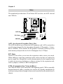
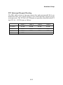
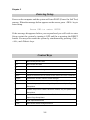
VIA Mainboard
User’s Manual
VIA P4XB-MA
Harnessing the Power of DDR266 SDRAM
for the Intel® Pentium® 4 Processor
Version 1.0
December 5, 2001
i
Copyright
Copyright by VIA Technologies Inc. (“VIA”). No part of this manual may
be reproduced or transmitted in any form without express written
authorization from VIA.
Trademarks
All trademarks are the property of their respective holders.
Data protection
All data should be backed-up prior to the installation of any drive unit or
storage peripheral. VIA will not be responsible for any loss of data resulting
from the use, disuse or misuse of this or any other VIA product.
No Warranty
VIA has made every effort to ensure the accuracy of the content of this
manual. However, it is possible that it may contain technical inaccuracies
or typographical or other errors. VIA will assume no liability for any
inaccuracy found in this publication, nor for damages, direct, indirect,
incidental, consequential or otherwise, that may result from such an
inaccuracy, including without limitation loss of data or profits.
VIA provides this manual “as is”, and does not issue a warranty of any
kind, express or implied, including without limitation implied warranties of
merchantability or fitness for a particular purpose.
The information provided in this manual is subject to change without
notice. VIA reserves the right to alter product designs, layouts or drivers
without notification.
ii
FCC-B Radio Frequency Interference Statement
This equipment has been tested and found to comply with the limits for a class
B digital device, pursuant to part 15 of the FCC rules. These limits are designed
to provide reasonable protection against harmful interference when the equipment is operated in a commercial environment. This equipment generates, uses
and can radiate radio frequency energy and, if not installed and used in accordance with the instruction manual, may cause harmful interference to radio
communications. Operation of this equipment in a residential area is likely to
cause harmful interference, in which case the user will be required to correct
the interference at his own expense.
Notice 1
The changes or modifications not expressly approved by the party responsible for compliance could void the user’s authority to operate the equipment.
Notice 2
Shielded interface cables and A.C. power cord, if any, must be used in order to
comply with the emission limits.
VOIR LA NOTICE D’INSTALLATION AVANT DE RACCORDER AU
RESEAU.
VIA P4XB-M
Tested to comply
with FCC Standard
For Home or Office Use
iii
Copyright Notice
We take every care in the preparation of this document, but no guarantee is
given as to the correctness of its contents. Our products are under continual
improvement and we reserve the right to make changes without notice.
Trademarks
All trademarks used in this manual are the property of their respective owners.
Intel and Pentium are registered trademarks of Intel Corporation.
PS/2 and OS/2 are registered trademarks of IBM Corporation.
Windows 95/98/2000 and Windows NT are registered trademarks of Microsoft.
Netware is a registered trademark of Novell.
Award is a registered trademark of Award Software Inc.
iv
Safety Instructions
NOTE
1.
2.
3.
4.
5.
Always read the safety instructions carefully.
Keep this User’s Manual for future reference.
Keep this equipment away from humidity.
Lay this equipment on a reliable flat surface before setting it up.
The openings on the enclosure are for air convection hence protects the
equipment from overheating. DO NOT COVER THE OPENINGS.
6. Make sure the voltage of the power source and adjust properly 110/220V
before connecting the equipment to the power inlet.
7. Place the power cord in such a way that people cannot step on it. Do not
place anything over the power cord.
8. Always unplug the power cord before inserting any add-on card or module.
9. All cautions and warnings on the equipment should be noted.
10. Never pour any liquid into the opening. Liquid can cause damage or electrical shock.
11. If any of the following situations arises, get the equipment checked by a
service personnel:
The power cord or plug is damaged
Liquid has penetrated into the equipment
The equipment has been exposed to moisture
The equipment has not work well or you can not get it work according
to User’s Manual.
The equipment has dropped and damaged
If the equipment has obvious sign of breakage
12. DO NOT LEAVE THIS EQUIPMENT IN AN ENVIRONMENT
UNCONDITIONED, STORAGE TEMPERATURE ABOVE 600 C (1400F), IT
MAY DAMAGE THE EQUIPMENT.
CAUTION: Explosion or serious damage may occur if the battery is
incorrectly replaced. Replace only with the same or
equivalent type recommended by the manufacturer.
v
Box Contents
•
1 x VIA Mainboard
•
1 x User’s manual
•
1 x Floppy ribbon cable
•
1 x ATA-66/100 Hard drive ribbon cable
•
1 x 2 Port USB Module
•
1 x Driver Utilities CD
vi
CONTENTS
Chapter 1. Specifications ......................................................................... 1-1
Mainboard Specifications .................................................................... 1-2
Mainboard Layout ............................................................................... 1-4
Chapter 2. Installation .............................................................................. 2-1
CPU ...................................................................................................... 2-2
CPU Installation Procedure ........................................................... 2-2
Installing the CPU Fan .................................................................. 2-3
CPU Core Speed Derivation Procedure ......................................... 2-4
Memory Installation ............................................................................. 2-5
DDR SDRAM Module Installation Procedures ............................. 2-6
Power Supply ....................................................................................... 2-7
ATX 20-Pin Power Connector: JWR1 ............................................ 2-7
ATX 12V Power Connector: JPW1 ................................................ 2-7
Back Panel ............................................................................................ 2-8
Mouse Connector: JKBMS1 ......................................................... 2-8
Keyboard Connector: JKBMS1 ..................................................... 2-8
LAN Jack (RJ-45) ........................................................................... 2-8
USB Connectors ............................................................................ 2-8
Serial Port Connectors: COM A & COM B .................................... 2-8
Joystick/Midi Connector ............................................................... 2-8
Audio Port Connectors ................................................................. 2-9
Parallel Port Connector: LPT1 ........................................................ 2-9
Connectors ......................................................................................... 2-10
Floppy Disk Drive Connector: FDD1 ........................................... 2-10
Power Saving Switch Connector: JGS1 ........................................ 2-10
Hard Disk Connectors: IDE1 & IDE2 ........................................... 2-11
Case Connector: JFP2 .................................................................. 2-12
vii
HDD LED ..................................................................................... 2-13
CD-In Connector: J2 .................................................................... 2-14
Aux Line-In Connector: J6 ........................................................... 2-14
Modem-In Connector: J5 ............................................................. 2-14
IrDA Infrared Module Connector: IR1 & IR2 .............................. 2-15
Front Panel Audio Connector: JAUDIO1 .................................... 2-16
Wake On Ring Connector: JMDM1 ............................................. 2-17
Wake On LAN Connector: JWOL1 .............................................. 2-17
Fan Power Connectors: PFAN1/SFAN1 ...................................... 2-18
USB Front Connector: USB2 (Intel spec) .................................... 2-19
Remote Power On/Off Switch Connector: JRMS1 ....................... 2-20
Jumpers .............................................................................................. 2-21
Clear CMOS Jumper: JBAT1 ........................................................ 2-21
Slots ................................................................................................... 2-22
AGP (Accelerated Graphics Port) Slot ......................................... 2-22
PCI Slots ...................................................................................... 2-22
CNR (Communication Network Riser) ......................................... 2-22
PCI Interrupt Request Routing .................................................... 2-23
Chapter 3. Award BIOS Setup .................................................................. 3-1
Entering Setup ...................................................................................... 3-2
Control Keys ........................................................................................ 3-2
Getting Help ......................................................................................... 3-3
The Main Menu ................................................................................... 3-4
Standard CMOS Features .................................................................... 3-6
Advanced BIOS Features .................................................................... 3-8
Advanced Chipset Features ............................................................... 3-11
Integrated Peripherals ........................................................................ 3-16
Power Management Setup ................................................................. 3-22
PNP/PCI Configurations ..................................................................... 3-26
viii
PC Health Status ................................................................................ 3-28
Frequency/Voltage Control ................................................................ 3-29
Load Fail-Safe Defaults ...................................................................... 3-31
Load Optimized Defaults .................................................................... 3-32
Supervisor/User Password ................................................................. 3-33
Save & Exit Setup ............................................................................... 3-35
Exit Without Saving ........................................................................... 3-36
Chapter 4. Driver Setup ............................................................................ 4-1
VIA Apollo P4X266A Chipset Driver ................................................... 4-2
Realtek ALC201A Audio Driver ........................................................... 4-7
ix
Introduction
1
Specifications
The VIA P4XB-MA Micro ATX mainboard is a high performance mainboard based on VIA Apollo P4X266A
chipset. The VIA Apollo P4X266A chipset brings support for high bandwidth DDR266 SDRAM to the Intel®
Pentium® 4 processor platform, and utilizes advanced VLink technology for optimal system efficiency. Designed
for the latest 478-pin Pentium® 4 processors, the P4XBMA offers the ideal platform for building powerful PCs
and workstations.
This chapter includes the following topics:
Mainboard Specifications
Mainboard Layout
1-1
1-2
1-4
Chapter 1
Mainboard Specifications
CPU
Supports 478-pin Intel® Pentium® 4 Processors
400MHz Front Side Bus.
Supports clock speeds from 1.5GHz to 2.0GHz.
Chipset
VIA Apollo P4X266A chipset
- 64bit DDR SDRAM memory interface (200/266MHz).
- 32bit AGP interface (66MHz) for 4x/2x mode.
- 8bit V-Link interface (66MHz) with peak bandwidth of 266MB/s.
- Dual IDE interface supports ATA-66 and ATA-100 modes.
Main Memory
Supports up to 2GB of DDR266 SDRAM (PC2100/PC1600).
Supports four memory banks using two 184-pin DDR266 DIMM slots.
2.5v DDR266 SDRAM.
Slots
One AGP (Accelerated Graphics Port) 4x slot.
Three PCI 2.2 32-bit PCI expansion slots (supports 3.3v/5v PCI bus interface).
One CNR (Communication Network Riser) slot.
On-Board IDE
z IDE controller on the south bridge of the VIA Apollo P4X266A chipset
provides IDE HDD/CD-ROM with PIO, Bus Master and Ultra DMA 33/66/
100 operation modes.
z Can connect up to four IDE devices.
On-Board Peripherals
On-Board Peripherals include:
- 1 floppy port supports 2 FDDs with 360K, 720K, 1.2M, 1.44M and
2.88Mbytes.
- 2 serial ports (COM A + COM B).
- 1 parallel port supports SPP/EPP/ECP mode.
- Up to 4 USB connections (2 back panel ports & 2 Front pin-headers).
- 1 IrDA connector for SIR/CIR/ASKIR/HPSIR.
- 1 RJ-45 LAN port.
1-2
Introduction
- 1 game (MIDI) port.
- 3 Audio jacks: line-out, line-in and mic-in.
Audio
AC97 link controller integrated in VT8233.
2-channel RealTek ALC201A software audio codec .
- Compliance with AC97 v2.2 spec.
- Meets PC2001 audio performance requirement.
LAN
RealTek RTL81000L 10/100 Base-T Fast Ethernet Controller.
- Supports 10MB/s and 100MB/s auto-negotiation operation.
- Compliance with PCI v2.2.
- Compliance with PC99 standard.
- Supports Wake-On-LAN and remote wake-up.
- Supports ACPI power management.
BIOS
Plug and Play Award BIOS
Dimension
Micro-ATX Form Factor: 24.3cm x 23.1cm.
Mounting
6 standard mounting holes.
1-3
Chapter 1
Mainboard Layout
VIA P4XB-MA MicroATX Mainboard
1-4
Hardware Setup
2
Installation
This chapter provides you with the information about
hardware setup procedures. While installating, be
careful in holding the components and follow the
installation procedures. Some components can be
damaged if they are installed incorrectly.
If possible, use a grounded wrist strap before handling computer components. Static electricity can
damage the components.
This chapter contains the following topics:
Central Processing Unit (CPU)
Memory Installation
Power Supply
Back Panel
Connectors
Jumpers
Slots
2-1
2-2
2-5
2-7
2-8
2-10
2-21
2-22
Chapter 2
Central Processing Unit: CPU
The VIA P4XB-MA mainboard supports the Intel® Pentium® 4 processor in the
478 pin package. When installing the CPU, make sure the CPU has a heat sink
and a cooling fan attached on the top to prevent overheating. If the heat sink
and cooling fan are not included with the CPU, contact your dealer to purchase
and install them before turning on the computer.
CPU Installation Procedures
1. Pull the lever sideways away
from the socket. Then raise the
lever up to a 90-degree
angle.
2. Look for the dot/cut edge. The
dot/cut edge should point towards the lever pivot. The
CPU will only fit in the correct
orientation.
3. Hold the CPU down firmly,
and then close the lever shut
to complete the installation.
WARNING!
Overheating will seriously damage the CPU and system.
Always make sure the cooling fan can work properly to
protect the CPU from overheating.
2-2
Hardware Setup
Installing the CPU Fan
To effectively dissipate heat generated by the CPU, you need to attach the
CPU cooling fan and heatsink on top of the CPU. Follow the instructions below
to install the Heatsink/Fan:
1. Locate the CPU and its retention
2. Position the heatsink onto the reten-
mechanism on the motherboard.
tion mechanism.
retention mechanism
3. Mount the fan on top of the heatsink.
4. Press the two levers down to fasten the
Press down the fan until its four clips
get wedged in the holes of the retention mechanism.
fan. Each lever can be pressed down in
only ONE direction.
levers
2-3
Chapter 2
5. Connect the fan power cable from the mounted fan to the 3-pin fan power connector
on the board.
fan power cable
CPU Core Speed Derivation Procedure
If
CPU Clock
Core/Bus ratio
then CPU core speed
WARNING!
=
=
=
=
=
100MHz
14
Host Clock x Core/Bus ratio
100MHz x 14
1.4GHz
Overclocking
This motherboard is designed to support overclocking.
However, please make sure your components are able to
tolerate the abnormal settings required for overclocking.
Any attempt to operate beyond product specifications is not
recommended. We do not guarantee the damages or risks
caused by operation beyond product specifications.
2-4
Hardware Setup
Memory Installation
The mainboard provides two 184-pin DDR DIMM (2.5V) with 4 memory banks.
To operate properly, at least one DIMM module must be installed.
You can install two PC1600/PC2100 DDR SDRAM modules on the DDR DIMM
slots (DDR 1~2).
DDR (Double Data Rate) SDRAM is similar to conventional SDRAM, but
doubles the rate by transfering data twice per cycle. It transfers data on both
the rising and falling edges of the clock. Conventional SDRAM only uses the
rising edge of the clock to transfer data.
DDR SDRAM uses 2.5 volts as opposed to 3.3 volts used in SDR SDRAM, and
requires 184-pin DIMM modules rather than 168-pin DIMM modules used by
SDR SDRAM.
Two types of DDR are available at the time of writing: PC1600 & PC2100.
PC1600 DDR SDRAM running at 100MHz will produce about 1.6GB/s memory
bandwidth. PC2100 running at 133MHz will produce 2.1GB/s memory bandwidth.
2-5
Chapter 2
DDR Module Installation Procedures
You can install either single sided or double sided 184-pin DDR DIMM
modules into DDR DIMM slots, depending on your requirements. As opposed to SDR DIMMs, DDR DIMMs have only one notch in the center of
module. The modules will only fit if placed in the correct position.
You can install memory modules in any of the following combinations:
Socket
M emory M odule
Total M emory
Slot 1
(Bank 0 & Bank 1)
32M B, 64M B, 128M B,
256M B, 512M B, 1GB
32M B~1GB
Slot 2
(Bank 2 & Bank 3)
32M B, 64M B, 128M B,
256M B, 512M B, 1GB
32M B~1GB
M aximum System M emory Supported
32M B~2GB
1. The DDR DIMM module has only one notch in the center.
Front View
Rear View
2. Insert the DDR module vertically into the DDR DIMM slot. Make sure the
notch is in the right position.
Volt
3. The plastic clips at sides of the DIMM slot will automatically close.
2-6
Hardware Setup
Power Supply
The P4XB-MA mainboard requires an ATX power supply for powering the
system. Before inserting the power supply connector, always make sure that
all components are installed correctly to ensure that no damage will be caused.
ATX 20-Pin Power Connector: JWR1
This connector is for the ATX power supply. To connect the ATX power
supply, make sure the plugs of the power supply is inserted in the proper
orientation and the pins are correctly aligned. Then, push down the power
supply firmly into the connector. The power connector supports an instant
power on function, which means the system will boot up immediately when the
power supply connector is inserted on the board.
ATX 12V Power Connector: JPW1
This 12V power connector is used to provide power to the CPU.
JWR1
10
20
1
11
JPW1
3
4
1
2
JWR1 Pin Definition
PIN
SIGNAL
PIN
SIGNAL
1
2
3
4
5
6
7
8
9
10
3.3V
3.3V
GND
5V
GND
5V
GND
PW_OK
5V_SB
12V
11
12
13
14
15
16
17
18
19
20
3.3V
-12V
GND
PS_ON
GND
GND
GND
-5V
5V
5V
2-7
JPW1 Pin Definition
PIN
SIGNAL
1
2
3
4
GND
GND
12V
12V
Chapter 2
Back Panel
The Back Panel of the VIA P4XB-MA mainboard provides the following
connectors:
PS/2 Mouse
RJ-45 LAN Port
Joystick/MIDI
LPT 1
COM A
PS/2 Keyboard
USB Port 2
COM B
Line Out
USB Port 1
Line In
Mic
Mouse Connector: JKBMS1
The mainboard provides a standard PS/2 mouse mini DIN connector for attaching a PS/2 mouse. You can plug a PS/2 mouse directly into this connector.
Keyboard Connector: JKBMS1
The mainboard provides a standard PS/2® keyboard mini DIN connector for
attaching a PS/2® keyboard. You can plug a PS/2® keyboard directly into this
connector.
LAN Jack (RJ-45)
The mainboard provides one standard RJ-45 jack for connection to Local Area
Network (LAN). You can connect a network cable to the LAN jack.
USB Connectors
The mainboard provides a UHCI (Universal Host Controller Interface) Universal Serial Bus root for attaching USB devices such as keyboard, mouse or other
USB-compatible devices. You can plug the USB device directly into ths
connector.
Serial Port Connector: COM A & COM B
The mainboard offers two 9-pin male serial port connectors (COM A & COM
B). You can attach a serial mouse or other serial devices directly to these ports.
Joystick/Midi Connectors
You can connect a joystick or game pad to this connector.
2-8
Hardware Setup
Audio Port Connectors
Line Out is a connector for Speakers or Headphones. Line In is used for an
external CD player, tape player, or other audio devices. Mic In is a connector
for microphones.
Parallel Port Connector: LPT1
The mainboard provides a 25-pin female centronic connector for LPT. A parallel port is a standard printer port that supports Enhanced Parallel Port (EPP)
and Extended Capabilities Parallel Port (ECP) mode.
2-9
Chapter 2
Connectors
The P4XB-MA mainboard provides connectors for FDD, IDE HDD, case,
modem, LAN, USB Ports, IR module and CPU/System FAN.
Floppy Disk Drive Connector: FDD1
The standard floppy disk drive connector supports 360K, 720K, 1.2M, 1.44M
and 2.88M floppy disk types.
Power Saving Switch Connector: JGS1
This connector is for attaching a power saving switch. Pressing the switch
once will enter the system into sleep/suspend state. Pressing any key will wake
up the system.
JGS1
2-10
Hardware Setup
Hard Disk Connectors: IDE1 & IDE2
The mainboard has a 32-bit Enhanced PCI IDE and Ultra DMA 33/66/100 controller that provides PIO mode 0~4, Bus Master, and Ultra DMA/33/66/100
functions. You can connect up to four hard disk drives, CD-ROM, 120MB
Floppy (reserved for future BIOS) and other devices. These connectors utilize
the provided IDE hard disk cable.
IDE1 (Primary IDE Connector)
The first hard drive should always be connected to IDE1. IDE1 can
connect a Master and a Slave drive. You must configure the second
hard drive to Slave mode by setting the jumper accordingly.
IDE2 (Secondary IDE Connector)
IDE2 can also connect a Master and a Slave drive.
TIP: If you install two hard disks on cable, you must configure the
second drive to Slave mode by setting its jumper. Refer to the hard disk
documentation supplied by hard disk vendors for jumper setting
instructions.
2-11
Chapter 2
Case Connector: JFP2
The case connector JFP2 allows you to connect to the the Power Switch,
Reset Switch, Power LED and HDD LED on the case.
1 2
HDD
LED
Power
LED
Reset
Switch
Power
Switch
Reserved
9 10
JFP2
JFP2 Pin Definition
Pin
Description
Pin
Description
1
*HDD_LED+
2
PWR_LED G
3
HDD_LED-
4
PWR_LED Y
5
RESET-
6
PWR_SW+
7
RESET+
8
PWR_SW-
9
RSVD_DNU
10
NC
* Hard disk LED pullup (330 ohm) to +5V
Power Switch
Connect to a 2-pin push button switch.
Reset Switch
Reset switch is used to reboot the system rather than turning the power ON/
OFF. Avoid rebooting while the HDD is working. You can connect the Reset
switch from the system case to this pin.
Power LED
The Power LED is lit while the system power is on. There are two types of LEDs
you can connect from the system case to the pin:
2-12
Hardware Setup
2-pin single color power LED: The power LED is not able to change its
color. Therefore, you can only choose Blinking in the BIOS utility for
the power LED to indicate the suspend/sleep mode.
2-pin dual color power LED: The 2-pin power LED can change its color
to indicate different system states. Therefore, you can select either
Blinking or Dual (color) for the power LED to show the suspend/sleep
mode.
z
z
When you select Blinking:
LED Status
Description
Steady Green
The system is in the full-on mode.
Blinking
The system enters the suspend/sleep mode.
When you select Dual (color):
LED Status
Description
Steady Green
The system is in the full-on mode.
Steady Orange
The system enters the suspend/sleep mode.
HDDLED
The HDD LED shows the activity of a hard disk drive connected to the IDE1 or
IDE2 connector. Avoid turning the power off while the HDD is working. You
can connect the HDD LED from the system case to this pin.
2-13
Chapter 2
CD-In Connector: J2
This connector is for the CD-ROM audio connector.
Aux Line-In Connector: J6
This connector is for a DVD add-on card with Line-in connector.
Modem-In Connector: J5
This connector is for a modem with internal audio connector.
J2
R
GND
L
J6
R
GND
L
J5
Mono_Out
GND
Phone_In
2-14
Hardware Setup
IrDA Infrared Module Connectors: IR1 & IR2
These connectors allow you to connect to IrDA Infrared modules. You must
configure the settings through the BIOS setup to use the IR function. The
difference between IR1 & IR2 is that IR2 is compliant to the3 Intel Front Panel
I/O Connectivity Design Guide.
6
5
2
1
IR2
1
IR1
IR1 Pin Definition
Pin Signal
1
VCC
2
NC
3
IRRX
4
GND
5
IRTX
2-15
IR2 Pin Definition
Pin Signal
1
Not assigned
2
NC
3
VCC
4
GND
5
IRTX
6
IRRX
Chapter 2
Front Panel Audio Connector: JAUDIO1
You can connect an optional audio connector to the Front Panel Audio pinheader. Pin numbers 1 to 10 of the audio pin header are compliant to the Intel
Front Panel I/O Connectivity Design Guide.
19
9
1
20
10
2
JAUDIO1
JAUDIO1 Pin Definition (1~10)
Pin
Signal
Description
1
2
3
4
5
6
7
8
9
10
AUD_MIC
AUD_GND
AUD_MIC_BIAS
AUD_VCC
AUD_FPOUT_R
AUD_RET_R
HP_ON
NC
AUD_FPOUT_L
AUD_RET_L
Front Panel Microphone input signal
Ground used by Analog Audio Circuits
Microphone Power
Filtered +5V used by Analog Audio Circuits
Right Channel Audio signal to Front Panel
Right Channel Audio signal Return from Front Panel
RSVD for future use to control Headphone Amplifier
No Connection
Left Channel Audio signal to Front Panel
Left Channel Audio signal Return from Front Panel
JAUDIO1 Pin Definition (11~20)
Pin
Signal
Description
11
12
13
14
15
16
17
18
19
20
AUD_MIC
AUD_GND
AUD_FPOUT_R
AUD_RET_R
AUD_FPOUT_L
AUD_RET_L
AUD_GND
NC
LINE-IN-R
LINE-IN-L
Front Panel Microphone input signal
Ground used by Analog Audio Circuits
Right Channel Audio signal to Front Panel
Right Channel Audio signal Return from Front Panel
Left Channel Audio signal to Front Panel
Left Channel Audio signal Return from Front Panel
Ground used by Analog Audio Circuits
No Connection
Line in Right
Line in Left
2-16
Hardware Setup
Wake On Ring Connector: JMDM1
This connector allows you to connect to a modem card with the Wake On Ring
function. The connector will power up the system when a signal is received
through the modem card.
5VSB
NC
MDM_WAKEUP
GND
NC
1
JMDM1
Wake On LAN Connector: JWOL1
This connector allows you to connect to a LAN card with Wake On LAN
function. You can wake up the computer via remote control through a local area
network (LAN).
1
5VSB
GND
MP_WAKEUP
JWOL1
2-17
Chapter 2
Fan Power Connectors: PFAN1/SFAN1
The PFAN1 (processor fan) & SFAN1 (system fan) connectors provide +12V
power supply for the system cooling fan, via a three-pin connector. When
connecting the wire to the connectors, always take note that the red wire is the
positive and should be connected to the +12V, the black wire is Ground and
should be connected to GND. If the mainboard has a System Hardware Monitor chipset on-board, you must use a specially designed fan with speed sensor
to take advantage of the CPU fan control.
GND
+12V
SENSOR
PFAN1
GND
+12V
SENSOR
SFAN1
NOTE: Always consult the vendor for proper CPU cooling fan.
2-18
Hardware Setup
USB Front Connector: USB2 (Intel spec)
The mainboard provides a front Universal Serial Bus (USB) connector for connecting additional USB devices. This USB2 connector is compliant to the Intel
Front Panel I/O Connectivity Design Guide.
10
9
2
1
USB2 Pin Definition
2-19
Pin
Description
Pin
Description
1
VCC
2
VCC
3
-DATA3
4
-DATA2
5
+DATA3
6
+DATA2
7
GND
8
GND
9
NC
10
Overcurrent
Signal
Chapter 2
Remote Power On/Off Switch Connector: JRMS1
Connects to a 2-pin push button switch. When the system is off, pressing the
button will turn the system on. When the system is on, pressing the button
once will enter the system to the sleep/suspend state. If the button is pressed
for more than four seconds, the system will be turned off. To change the setup,
go to the BIOS Power Management Setup.
JRMS1
2-20
Hardware Setup
Jumpers
The mainboard provides one jumper for setting the computer’s functions. This
section will explain how to change your mainboard’s function through the use
of the jumper.
Clear CMOS Jumper: JBAT1
There is a CMOS RAM on board that has a power supply from external battery
to keep the data of system configuration. With the CMOS RAM, the system
can automatically boot OS every time it is turned on. That battery has long life
time for at least 5 years. If you want to clear the system configuration, use the
JBAT1 (Clear CMOS Jumper ) to clear data. Follow the instructions below to
clear the data:
1
JBAT1
1
1
3
3
Keep CMOS
WARNING!
Clear CMOS
You can clear CMOS by shorting 2-3 pin while the
system is off. Then return to 1-2 pin position. Avoid
clearing the CMOS while the system is on; it will
damage the mainboard.
2-21
Chapter 2
Slots
The mainboard provides three 32-bit Master PCI bus slots, one AGP slot and
one CNR slot.
AGP Slot
PCI Slots
CNR Slot
AGP (Accelerated Graphics Port) Slot
The AGP slot allows you to insert the AGP graphics card. AGP is an interface
specification designed for the throughput demands of 3D graphics. It introduces a 66MHz, 32-bit channel for the graphics controller to directly access
main memory and provides one level of throughput: 4x (1.07Gbps).
PCI Slots
Three PCI slots allow you to insert the expansion cards to meet your needs.
When adding or removing expansion cards, make sure that you unplug the
power supply first. Meanwhile, read the documentation for the expansion card
to make any necessary hardware or software settings for the expansion card,
such as jumpers, switches or BIOS configuration.
CNR (Communication Network Riser)
The CNR slot allows you to insert the CNR expansion cards. CNR is a specially
designed network, audio, or modem riser card for ATX family mainboards. Its
main processing is done through software and controlled by the motherboard’s
chipset.
2-22
Hardware Setup
PCI Interrupt Request Routing
The IRQ, abbreviation of interrupt request line and pronounced I-R-Q, are
hardware lines over which devices can send interrupt signals to the
microprocessor. The “PCI & LAN” IRQ pins are typically connected to the PCI
bus INT A# ~ INT D# pins as follows:
Order 1
Order 2
Order 3
Order 4
PCI Slot 1
INT A#
INT B#
INT C#
INT D#
PCI Slot 2
INT B#
INT C#
INT D#
INT A#
PCI Slot 3
INT C#
INT D#
INT A#
INT B#
LAN
INT B#
2-23
BIOS Setup
3
Chapter 3. BIOS Setup
BIOS Setup
Entering Setup
Control Keys
Getting Help
The Main Menu
Standard CMOS Features
Advanced BIOS Features
Advanced Chipset Features
Integrated Peripherals
Power Management Setup
PNP/PCI Configurations
PC Health Status
Frequency/Voltage Control
Load Fail-Safe Defaults
Load Optimized Defaults
Set Supervisor/User Password
Save & Exit Setup
Exit Without Saving
3-1
3-2
3-2
3-3
3-4
3-6
3-8
3-11
3-16
3-22
3-26
3-28
3-29
3-31
3-32
3-33
3-35
3-36
Chapter 3
Entering Setup
Power on the computer and the system will start POST (Power On Self Test)
process. When the message below appears on the screen, press <DEL> key to
enter Setup.
Press DEL to enter SETUP
If the message disappears before you respond and you still wish to enter
Setup, restart the system by turning it OFF and On or pressing the RESET
button. You may also restart the system by simultaneously pressing <Ctrl>,
<Alt>, and <Delete> keys.
Control Keys
<n>
Move to the previous item
<p>
Move to the next item
<m>
Move to the item in the left hand
<o>
Move to the item in the right hand
<Enter>
Select the item
<Esc>
Jumps to the Exit menu or returns to the main menu from a submenu
<+/PU>
Increase the numeric value or make changes
<-/PD>
Decrease the numeric value or make changes
<F1>
General help, only for Status Page Setup Menu and Option Page
Setup Menu
<F5>
Restore the previous CMOS value from CMOS, only for Option Page
Setup Menu
<F6>
Load the default CMOS value from Fail-Safe default table, only for
Option Page Setup Menu
<F7>
Load Optimized defaults
<F10>
Save all the CMOS changes and exit
3-2
BIOS Setup
Getting Help
After entering the Setup menu, the first menu you will see is the Main Menu.
Main Menu
The main menu lists the setup functions you can make changes to. You can use
the control keys (hi ) to select the item. The on-line description of the highlighted setup function is displayed at the bottom of the screen.
Sub-Menu
If you find a right pointer symbol (as shown in
the right view) appears to the left of certain fields
that means a sub-menu containing additional
options can be launched from this field. You can
use control keys (hi ) to highlight the field and
press <Enter> to call up the sub-menu. Then you
can use the control keys to enter values and
move from field to field within a sub-menu. If
you want to return to the main menu, just press
<Esc >.
IDE
IDE
IDE
IDE
Primary Master
Primary Slave
Secondary Master
Secondary Slave
General Help <F1>
The BIOS setup program provides a General Help screen. You can call up this
screen from any menu by simply pressing <F1>. The Help screen lists the
appropriate keys to use and the possible selections for the highlighted item.
Press <Esc> to exit the Help screen.
3-3
Chapter 3
The Main Menu
Once you enter Award® BIOS CMOS Setup Utility, the Main Menu (Figure 1)
will appear on the screen. The Main Menu allows you to select from twelve
setup functions and two exit choices. Use arrow keys to select among the items
and press <Enter> to accept or enter the sub-menu.
Standard CMOS Features
Use this Menu for basic system configurations.
Advanced BIOS Features
Use this menu to set the Advanced Features available on your system.
Advanced Chipset Features
Use this menu to change the values in the chipset registers and optimize your
system’s performance.
Integrated Peripherals
Use this menu to specify your settings for integrated peripherals.
Power Management Setup
Use this menu to specify your settings for power management.
PnP/PCI Configurations
This entry appears if your system supports PnP/PCI.
3-4
BIOS Setup
PC Health Status
This entry shows your PC health status.
Frequency/Voltage Control
Use this menu to specify your settings for frequency/voltage control.
Load Fail-Safe Defaults
Use this menu to load factory default settings in the BIOS for stable system running
Load Optimized Defaults
Use this menu to load factory default settings into the BIOS for optimal and
stable system operations.
Supervisor/User Password
Use this menu to set User and Supervisor Passwords.
Save & Exit Setup
Save CMOS value changes to CMOS and exit setup.
Exit Without Saving
Abandon all CMOS value changes and exit setup.
3-5
Chapter 3
Standard CMOS Features
The items in Standard CMOS Features Menu are divided into 10 categories.
Each category includes no, one or more than one setup items. Use the arrow
keys to highlight the item and then use the <PgUp> or <PgDn> keys to select
the value you want in each item.
Date
The date format is <day><month> <date> <year>.
day Day of the week, from Sun to Sat, determined by BIOS. Read-only.
month The month from Jan. through Dec.
date The date from 1 to 31 can be keyed by numeric function keys.
year The year, depends on the year of the BIOS
Time
The time format is <hour> <minute> <second>.
IDE Primary/Secondary Master/Slave
Press PgUp/<+> or PgDn/<-> to select Manual, None, Auto type. Note that the
specifications of your drive must match with the drive table. The hard disk will
not work properly if you enter improper information for this category. If your
hard disk drive type is not matched or listed, you can use Manual to define
your own drive type manually.
If you select Manual, related information is asked to be entered to the follow-
3-6
BIOS Setup
ing items. Enter the information directly from the keyboard. This information
should be provided in the documentation from your hard disk vendor or the
system manufacturer.
If the controller of HDD interface is SCSI, the selection shall be “None”.
If the controller of HDD interface is CD-ROM, the selection shall be “None”.
Access Mode
The settings are CHS, LBA, Large, Auto.
Capacity
The formatted size of the storage device.
Cylinder
Number of cylinders.
Head
Number of heads.
Precomp
Write precompensation.
Landing Zone Cylinder location of the landing zone.
Sector
Number of sectors.
Drive A/B
This item allows you to set the type of floppy drives installed. Available
options are None, 360K, 5.25 in., 1.2M, 5.25 in., 720K, 3.5 in., 1.44M, 3.5 in.,
2.88M, 3.5 in.
Video
The setting controls the type of video adapter used for the primary monitor of
the system. Available options are EGA/VGA , CGA 40, CGA 80 and Mono.
Halt On
The setting determines whether the system will stop if an error is detected at
boot. Available options are:
All Errors
No Errors
All, But Keyboard
All, But Diskette
All, But Disk/Key
The system stops when any error is detected.
The system doesn’t stop for any detected error.
The system doesn’t stop for a keyboard error.
The system doesn’t stop for a disk error.
The system doesn’t stop for either a disk or a
keyboard error.
3-7
Chapter 3
Advanced BIOS Features
Anti-Virus Protection
The item is to set the Virus Warning feature for IDE Hard Disk boot sector
protection. If the function is enabled and any attempt to write data into this
area is made, BIOS will display a warning message on screen and beep. Settings:
Disabled and Enabled.
CPU L1 & L2 Cache
The item allows you to turn on or off CPU’s internal (L1) and external (L2)
cache. Settings: Enabled and Disabled.
CPU L2 Cache ECC Checking
This setting allows you to enable or disable the ECC (Error-Correcting Code)
feature for error detection and correction when data passes through L2 cache
memory. Setting options: Enabled and Disabled.
Quick Power On Self Test
The option speeds up Power On Self Test (POST) after you power on the
computer. When setting the item to Enabled, BIOS will shorten or skip some
check items during POST. Settings: Enabled and Disabled.
First/Second/Third Boot Device
The items allow you to set the sequence of boot devices where BIOS attempts
3-8
BIOS Setup
to load the disk operating system. The settings are:
Floppy
The system will boot from floppy drive.
LS120
The system will boot from LS-120 drive.
HDD-0
The system will boot from the first HDD.
SCSI
The system will boot from the SCSI.
CDROM
The system will boot from the CD-ROM.
HDD-1
The system will boot from the second HDD.
HDD-2
The system will boot from the third HDD.
HDD-3
The system will boot from the fourth HDD.
ZIP
The system will boot from ATAPI ZIP drive.
LAN
The system will boot from the Network drive.
Disabled
Disable this sequence.
Boot Other Device
Setting the option to Enabled allows the system to try to boot from other
device if the system fails to boot from the First/Second/Third boot device.
Swap Floppy Drive
Setting to Enabled will swap floppy drives A: and B:.
Boot Up Floppy Seek
Setting to Enabled will make BIOS seek floppy drive A: before booting the
system. Settings: Disabled and Enabled.
Boot Up NumLock Status
This item is to set the NumLock status when the system is powered on. Setting
to On will turn on the Num Lock key when the system is powered on. Setting to
Off will allow end users to use the arrow keys on the numeric keypad. Settings:
On and Off.
Gate A20 Option
This item is to set the Gate A20 status. A20 refers to the first 64KB of extended
memory. When the default value Fast is selected, the Gate A20 is controlled by
Port92 or chipset specific method resulting in faster system performance. When
Normal is selected, A20 is controlled by a keyboard controller or chipset hardware.
3-9
Chapter 3
Typematic Rate Setting
This item is used to enable or disable the typematic rate setting including
Typematic Rate & Typematic Delay.
Typematic Rate (Chars/Sec)
After Typematic Rate Setting is enabled, this item allows you to set the rate
(characters/second) at which the keys are accelerated. Settings: 6, 8, 10, 12,
15, 20, 24 and 30.
Typematic Delay (Msec)
This item allows you to select the delay between when the key was first pressed
and when the acceleration begins. Settings: 250, 500, 750 and 1000.
Security Option
This specifies the type of BIOS password protection that is implemented. Settings are described below:
Option
Setup
Description
The password prompt appears only when end users try to
run Setup.
System
A password prompt appears every time when the computer is powered on or when end users try to run Setup.
OS Select For DRAM > 64MB
This allows you to run the OS/2® operating system with DRAM greater than
64MB. Setting options: Non-OS2, OS2.
Video BIOS Cacheable
Selecting Enabled allows caching of the video BIOS ROM at C0000h to C7FFFh,
resulting in better video performance. However, if any program writes to this
memory area, a system error may result. Settings: Enabled and Disabled.
3-10
BIOS Setup
Advanced Chipset Features
The Advanced Chipset Features setup option is used to change the values of
the chipset registers. These registers control most of the system options in the
computer.
Note: Change these settings only if you are familiar with the chipset.
DRAM Clock/Drive Control
Press <Enter> to enter the sub-menu and the following screen appears:
DRAM Timing by SPD
This setting determines whether DRAM timing is configured by reading
3-11
Chapter 3
the contents of the SPD (Serial Presence Detect) EPROM on the DRAM
module. Selecting Yes makes SDRAM Cycle Length and Bank Interleave
automatically determined by BIOS according to the configurations on the
SPD. Setting options: Yes, No.
DRAM Frequency (MHz)
The chipset supports synchronous and asynchronous mode between
host clock and DRAM clock frequency. Available settings are:
Auto:
DRAM clock frequency is automatically
determined.
HCLK:
The DRAM clock will be equal to the Host clock.
HCLK+33: The DRAM clock will be equal to the Host clock
plus 33MHz. For example, if the Host clock is
100MHz, the DRAM clock will 133MHz.
DRAM CAS Latency
The field controls the CAS latency, which determines the timing delay
before SDRAM starts a read command after receiving it. Setting options:
2, 2.5, 3 (clock cycles), Auto. 2 increases system performance while 2.5
provides more stable system performance for DDR SDRAM.
Bank Interleave
This setting determines the bank interleave for the installed SDRAM.
Setting options: Disabled, Auto.
Row Precharge
This setting allows you to select the number of DRAM clocks allocated
for the Row Address Strobe (RAS#) signal to accumulate its charge before the DRAM is refreshed. If insufficient time is allowed, refresh may be
incomplete and data lost. The lower the timing numbers, the faster the
memory performance. Setting options: 3T, 2T, Auto.
RAS Pulse
This setting allows you to select the number of DRAM clock cycles
allotted for the RAS pulse width, according to DRAM specifications.The
lower the timing numbers, the faster the memory performance. Setting
options: 6T, 5T, Auto.
3-12
BIOS Setup
RAS to CAS
When DRAM is refreshed, both rows and columns are addressed
separately. This setup item allows you to determine the timing of the
transition from RAS (row address strobe) to CAS (column address strobe).
The lower the timing numbers, the faster the memory performance. Setting options: 3T, 2T, Auto.
Burst Length
This setting allows you to set the size for Burst-Length for DRAM. The
bigger the sizes, the faster the system addresses memory. Setting options:
4, 8, Auto.
DRAM Command Rate
This setting controls the DRAM command rate. Selecting 1T allows DRAM
signal controller to run at 1T (T=clock cycles) rate. Selecting 2T makes
DRAM signal controller run at 2T rate. 1T is faster than 2T. Setting options:
2T, 1T.
AGP & P2P Bridge Control
Press <Enter> to enter the sub-menu and the following screen appears:
AGP Aperture Size
This setting controls just how much system RAM can be allocated to
AGP for video purposes. The aperture is a portion of the PCI memory
3-13
Chapter 3
address range dedicated to graphics memory address space. Host cycles
that hit the aperture range are forwarded to the AGP without any translation.
Setting options: 4MB, 8MB, 16MB, 32MB, 64MB, 128MB, and 256MB.
AGP Driving Control
The setting is used to adjust AGP driving force. Selecting Manual allows
you to type a AGP driving force in AGP Driving Value. It is strongly
suggested to select Auto to avoid causing any system error. Setting
options: Auto, Manual.
AGP Fast Write
This setting enables/disables the AGP Fast Write feature. The Fast Write
technology allows CPU to write directly into the graphics card without
passing anything through system memory and improves 4X speed
accordingly. Select Enabled only when your AGP card supports the feature.
Setting options: Enabled, Disabled.
CPU & PCI Bus Control
Press <Enter> to enter the sub-menu and the following screen appears:
CPU to PCI Write Buffer
When Enabled, CPU can write up to four words of data to the PCI write
buffer before CPU must wait for PCI bus cycle to finish. If Disabled, CPU
must wait after each write cycle until PCI bus signals that it is ready to
3-14
BIOS Setup
receive more data. Setting options: Enabled, Disabled.
PCI Master 0 WS Write
When Enabled, writes to the PCI bus are executed with zero wait state.
Setting options: Enabled, Disabled.
PCI Delay Transaction
The chipset has an embedded 32-bit posted write buffer to support delay
transaction cycles. Select Enabled to support compliance with PCI specification version 2.1. Setting options: Enabled, Disabled.
System BIOS Cacheable
Selecting enabled allows write through caching of the system BIOS ROM at
F0000h to FFFFF except F8000 to F8FFF, resulting in better system BIOS
performance.
3-15
Chapter 3
Integrated Peripherals
Onboard LAN Chip
This setting enables the onboard RTL8100L LAN chip. Setting options: Enabled,
Disabled.
VIA OnChip IDE Device
Press <Enter> to enter the sub-menu and the following screen appears:
3-16
BIOS Setup
OnChip IDE Channel 0/1
The integrated peripheral controller contains an IDE interface with support for two IDE channels. Choose Enabled to activate each channel
separately. Setting options: Disabled, Enabled.
Primary/Secondary Master/Slave PIO
The four fields allow you to set a PIO (Programmed Input/Output) mode
for each of the four IDE devices that the onboard IDE interface supports.
Modes 0~4 provide increased performance. In Auto mode, BIOS automatically determines the best mode for each IDE device.
Primary/Secondary Master/Slave UDMA
Ultra DMA implementation is possible only if your IDE device supports it
and your operating environment contains a DMA driver. If both your
hard drive and software support Ultra DMA 33, select Auto to enable
BIOS support. Setting options: Auto, Disabled.
IDE HDD Block Mode
This setting allows your hard disk controller to use the fast block mode to
transfer data to and from the hard disk drive. Block mode is also called
Block Transfer, Multiple Commands or Multiple Sector Read/Write. Selecting enabled mode enables the IDE controller to use block mode; Disabled mode allows the controller to use standard mode.
3-17
Chapter 3
VIA OnChip PCI Device
Press <Enter> to enter the sub-menu and the following screen appears:
VIA-3058 AC97 Audio
Auto allows the mainboard to detect whether an audio device is used. If
the device is detected, the onboard VIA AC’97 (Audio Codec’97) controller will be enabled; if not, it is disabled. Disable the controller if you
want to use other controller cards to connect an audio device. Setting
options: Auto, Disabled.
VIA-3068 MC97 Modem
Auto allows the mainboard to detect whether a modem is used. If a modem
is used, the onboard VIA MC’97 (Modem Codec’97) controller will be
enabled; if not, it is disabled. Disable the controller if you want to use
other controller cards to connect to a modem. Setting options: Auto,
3-18
BIOS Setup
Winbond Super I/O Device
Press <enter> to enter the sub-menu and the following screen appears:
Onboard FDC Controller
This setting enables or disables the onboard Floppy controller. Select
Enabled when you have installed a floppy disk drive and want to use it.
Onboard Serial Port 1/2
This setting specifies the base I/O port address and IRQ for the onboard
Serial Port A / Serial Port B. Selecting Auto allows the BIOS to automatically determine the correct base I/O port address. Settings: Disabled,
3F8/IRQ4, 2F8/IRQ3, 3E8/IRQ4, 2E8/IRQ3 and Auto.
UART Mode Select
The field allows you to specify the operation mode for serial port “COM
B”. Settings are:
Normal: RS-232C Serial Port
IrDA:
IrDA-compliant Serial Infrared Port
ASKIR: Amplitude Shift Keyed Infrared Port
RxD, TxD Active
This setting controls the receiving and transmitting speed of the IR pe3-19
Chapter 3
ripheral in use. Setting options: Hi/Hi, Hi/Lo, Lo/Hi, Lo/Lo.
IR Transmission Delay
This setting determines whether the IR transmission rate will be delayed
while converting to receiving mode. Setting options: Disabled, Enabled.
UR2 Duplex Mode
This setting controls the operating mode of IR transmission/reception.
Setting options: Full, Half. Under Full Duplex mode, synchronous, bidirectional transmission/reception is allowed. Under Half Duplex mode,
only asynchronous, bi-directional transmission/reception is allowed.
Use IR Pins
Please consult your IR peripheral documentation to select the correct
setting of the TxD and RxD signals. Setting options: RxD2/TxD2, IRRx2Tx2.
Onboard Parallel Port
This specifies the I/O port address and IRQ of the onboard parallel port.
Settings: 378/IRQ7, 278/IRQ5, 3BC/IRQ7 and Disabled.
Parallel Port Mode
SPP : Standard Parallel Port
EPP : Enhanced Parallel Port
ECP : Extended Capability Port
ECP + EPP: Extended Capability Port + Enhanced Parallel Port
SPP/EPP/ECP/ECP+EPP
To operate the onboard parallel port as Standard Parallel Port only, choose
“SPP.” To operate the onboard parallel port in the EPP mode
simultaneously, choose “EPP.” By choosing “ECP”, the onboard parallel
port will operate in ECP mode only. Choosing “ECP + EPP” will allow the
onboard parallel port to support both the ECP and EPP modes simultaneously.
EPP Mode Select
The onboard parallel port is EPP Spec. compliant, so after the user chooses
the onboard parallel port with the EPP function, the following message
will be displayed on the screen: “EPP Mode Select.” At this time either
3-20
BIOS Setup
EPP 1.7 spec or EPP 1.9 spec can be selected.
ECP Mode Use DMA
The ECP mode has to use the DMA channel, so choose the onboard
parallel port with the ECP feature. After selecting it, the following message will appear: “ECP Mode Use DMA.” At this time, the user can choose
between DMA channel 3 or 1.
PWRON After PWR-Fail
This setting specifies whether your system will reboot after a power failure or interrupts occurs. Available settins are:
Off
Leaves the computer in the power off state.
On
Reboots the computer.
Former-Sts Restores the system to the status before power failure or
interrupt occurs.
Game Port Address/Midi Port Address
This setting disables or assigns an address for the onboard game/midi
port.
Midi Port IRQ
This setting specifies an IRQ for the onboard midi port.
Init Display First
This setting specifies which VGA card is your primary graphics adaptor. Available options: PCI Slot, AGP.
Onchip USB Controller
This setting allows you to activate the onchip USB controller. Available settings:
All Disabled, All enabled, 1 USB Port, 2 USB Port.
USB Keyboard/Mouse Support
Set to enabled if you need to use a USB keyboard/mouse and the Operating
System does not support or have any USB drivers installed, such as DOS or
SCO Unix. Available settings: Disabled, Enabled.
3-21
Chapter 3
Power Management Setup
The Power Management Setup allows you to configure you system to most
effectively save energy while operating in a manner consistent with your own
style of computer use.
ACPI Function
This item is to activate the ACPI (Advanced Configuration and Power Management Interface) Function. If your operating system is ACPI-aware, such as
Windows 98SE/2000/ME, select Enabled. Settings: Enabled and Disabled.
Sleep State
This item specifies the power saving modes for ACPI function. Options are:
S1/POS
S3/STR
S1 & S3
The S1 sleep mode is a low power state. In this state, no
system context (CPU or chipset) is lost and hardware
maintains all system context.
The S3 sleep mode is a power-down state in which power
is supplied only to essential components such as main
memory and wake-capable devices and all system
contextis saved to main memory. The information stored
inmemory will be used to restore the PC to the previous
state when an “wake up” event occurs.
Supports both S1 and S3 sleep modes.
3-22
BIOS Setup
Power Management Option
This item is used to select the degree (or type) of power saving and is related
to these modes: Suspend Mode and HDD Power Down. There are three options for power management:
Min Saving Minimum Power Management. Suspend Mode = 1 Hour,
and HDD Power Down = 15 Min.
Max Saving Maximum Power Management. Suspend Mode = 1 Min,
and HDD Power Down = 1 Min.
User Define Allows end users to configure each mode separately.
HDD Power Down
If HDD activity is not detected for the length of time specified in this field, the
hard disk drive will be powered down while all other devices remain active.
Settings are Disable and 1 through 15 Min.
Doze Mode
After the selected period of system inactivity, the CPU clock runs at slower
speed while all other devices still operate at full speed. Settings are Disable, 1
Min, 2 Min, 4 Min, 6 Min, 8 Min, 10 Min, 20 Min, 30 Min, 40 Min and 1 Hour.
Suspend Mode
After the selected period of system inactivity, all devices except the CPU shut
off. Settings are Disabled, 1 Min, 2 Min, 4 Min, 8 Min, 12 Min, 20 Min, 30
Min, 40 Min and 1 Hour.
PM Control by APM
Setting to Yes will activate an Advanced Power Management (APM) device to
enhance Max Saving mode and stop CPU internal clock. Setting options: Yes,
No.
MODEM Use IRQ
Name the interrupt request (IRQ) line assigned to the modem (if any) on your
system. Activity of the selected IRQ always awakens the system. Settings are
3, 4, 5, 7, 9, 10, 11 and NA.
Soft-Off by PWRBTN
This feature allows users to configure the power button function. Settings are:
Instant-Off
The power button functions as a normal power-on/off button.
3-23
Chapter 3
Delay 4 Sec.
When you press the power button, the computer enters the suspend/sleep mode, but if the button is
pressed for more than four seconds, the computer is
turned off.
Power/Sleep LED
This setting determines how Power LED on the case indicates the sleep state.
Settings are:
Single LED The Power LED blinks to indicate the sleep state.
Dual LED
The Power LED changes its color to indicate the sleep
state.
IRQ/Event Activity Detect
Press <Enter> to enter the sub-menu and the following screen appears:
PS2KB Wakeup Select, PS2KB Wakeup from S3, PS2MS Wakeup from
S3, USB Resume from S3, VGA, LPT & COM, HDD & FDD, PCI Master, Wake Up On LID, PowerOn by PCI Card, Modem Ring Resume
These fields specify whether the system will be awakened from power
saving modes when activity or input signal of the specified hardware
peripheral or component is detected.
RTC Alarm Resume
The field is used to enable or disable the feature of booting up the system
on a scheduled time/date.
3-24
BIOS Setup
Date (of Month)
The field specifies the date for RTC Alarm Resume. Settings: 0~31.
Resume Time (hh:mm:ss)
The field specifies the time for RTC Alarm Resume. Format is <hour>
<minute><second>.
IRQs Activity Monitoring
Press Enter toenterthesub-menuandthefollowingscreenappears:
Primary INTR
Selecting ON will cause the system to wake up from power saving modes
if activity is detected from any enabled IRQ channels.
IRQ3~IRQ15
Enables or disables the monitoring of the specified IRQ line. If set to
Enabled, the activity of the specified IRQ line will prevent the system
from entering power saving modes or awaken it from power saving modes.
Note: IRQ (Interrupt Request) lines are system resources allocated to
I/O devices. When an I/O device needs to gain attention of the operating system, it signals this by causing an IRQ to occur. After receiving
the signal, when the operating system is ready, the system will interrupt itself and perform the service required by the I/O device.
3-25
Chapter 3
PNP/PCI Configurations
This section describes configuring the PCI bus system. PCI, or Personal Computer Interconnect, is a system which allows I/O devices to operate at speeds
nearing the speed the CPU itself uses when communicating with its own special components. This section covers some very technical items and it is
strongly recommended that only experienced users should make any changes
to the default settings.
PNP OS Installed
When set to Yes, BIOS will only initialize the PnP cards used for booting (VGA,
IDE, SCSI). The rest of the cards will be initialized by the PnP operating system
like Windows® 95 or 98. When set to No, BIOS will initialize all the PnP cards.
So, select Yes if the operating system is Plug & Play aware.
Reset Configuration Data
Normally, you leave this field Disabled. Select Enabled to reset Extended System Configuration Data (ESCD) when you exit Setup if you have installed a
new add-on and the system reconfiguration has caused such a serious conflict
that the operating system can not boot. The settings are: Enabled and Disabled.
Resource Controlled By
The Award Plug and Play BIOS has the capacity to automatically configure all
of the boot and Plug and Play compatible devices. However, this capability
means absolutely nothing unless you are using a Plug and Play operating
3-26
BIOS Setup
system such as Windows 95/98. If you set this field to “manual” choose specific resources by going into each of the sub menu that follows this field (a sub
menu is preceded by a “”). The settings are: Auto (ESCD), Manual.
IRQ Resources
The items are adjustable only when Resources Controlled By is set to Manual.
Press <Enter> and you will enter the sub-menu of the items. IRQ Resources list
IRQ 3/4/5/7/9/10/11/12/14/15 for users to set each IRQ a type depending on the
type of device using the IRQ. Settings are:
PCI Device
For Plug & Play compatible devices designed for PCI
bus architecture.
Reserved
The IRQ will be reserved for further request.
PCI/VGA Palette Snoop
When set to Enabled, multiple VGA devices operating on different buses can
handle data from the CPU on each set of palette registers on every video
device. Bit 5 of the command register in the PCI device configuration space is
the VGA Palette Snoop bit (0 is disabled). For example, if there are two VGA
devices in the computer (one PCI and one ISA) and the:
VGA Palette Snoop
Bit Setting
Action
Disabled
Data read or written by the CPU is only directed to the PCI
VGA device’s palette registers.
Enabled
Data read or written by the CPU is directed to both the PCI
VGA device’s palette registers and the ISA VGA device’s palette registers, permitting the palette registers of both VGA
devices to be identical.
The setting must be set to Enabled if any ISA bus adapter in the system
requires VGA palette snooping.
Assign IRQ For VGA/USB/ACPI
The settings specify IRQ for each of the hardware components. Auto allows
BIOS to determine the IRQ automatically.
3-27
Chapter 3
PC Health Status
This section displays the settings for monitoring the status of your CPU, fans,
and overall system status.
CPU Warning Temperature
If the CPU temperature reaches the upper limit preset in this setting, the warning mechanism will be activated. This helps you to prevent the CPU overheat
problem.
Current System, CPU Temperature/Current System, CPU Fan/Vcore/3.3V/
+5V/+12V/-12V/-5V/VBAT(V)/5VSB(V)
These items display the current status of all of the monitored hardware devices/components such as CPU voltages, temperatures and all fans’ speeds.
3-28
BIOS Setup
Frequency/Voltage Control
Auto Detect DIMM/PCI Clk
To reduce the occurrence of electromagnetic interference (EMI), the BIOS detects the presence or absence of components in DIMM and PCI slots and
turns off system clock generator pulses to empty slots. The settings are: Enabled, Disabled.
Spread Spectrum
When the motherboard’s clock generator pulses, the extreme values (spikes)
of the pulses creates EMI (Electromagnetic Interference). The Spread Spectrum function reduces the EMI generated by modulating the pulses so that the
spikes of the pulses are reduced to flatter curves. If you do not have any EMI
problem, leave the setting at Disabled for optimal system stability and
performance. But if you are plagued by EMI, setting to Enabled for EMI
reduction. Remember to disable Spread Spectrum if you are overclocking because even a 0.25% jitter can introduce a temporary boost in clockspeed of
25MHz (with a 1GHz CPU) which may just cause your overclocked processor
to lock up.
CPU Clock
This setting specifies the clock frequency of CPU host bus (FSB) and provides
a method for end-users to overclock the processor accordingly.
3-29
Chapter 3
CPU Ratio
This setting controls the multiplier that is used to determine the internal clock
speed of the processor relative to the external or motherboard clock speed.
3-30
BIOS Setup
Load Fail-Safe Defaults
This option allows users to restore all the BIOS settings to the default Fail-Safe
values. The Fail-Safe default settings are the settings set by the mainboard
manufacturer for stable running of the mainboard.
Pressing ‘Y’ loads the default Fail-Safe settings for stable system performance.
3-31
Chapter 3
Load Optimized Defaults
This option on the main menu allows users to restore all the BIOS settings to
the default Optimized values. The Optimized Defaults are the default values
also set by the mainboard manufacturer for both optimized and stable performance of the mainboard.
When you select Load Optimized Defaults, a message as below appears:
Pressing ‘Y’ loads the default values that are factory settings for optimal and
stable system performance.
3-32
BIOS Setup
Set Supervisor/User Password
When you select this function, a message as below will appear on the screen:
Type the password, up to eight characters in length, and press <Enter>. The
password typed now will clear any previously set password from CMOS
memory. You will be prompted to confirm the password. Re-type the password
and press <Enter>. You may also press <Esc> to abort the selection and not
enter a password.
To clear a set password, just press <Enter> when you are prompted to enter the
password. A message will show up confirming the password will be disabled.
Once the password is disabled, the system will boot and you can enter Setup
without entering any password.
When a password has been set, you will be prompted to enter it every time you
try to enter Setup. This prevents an unauthorized person from changing any
part of your system configuration.
Additionally, when a password is enabled, you can also have BIOS to request
a password each time the system is booted. This would prevent unauthorized
use of your computer. The setting to determine when the password prompt is
required is the Security Option of the Advanced BIOS Features menu. If the
Security Option is set to System, the password is required both at boot and at
3-33
Chapter 3
entry to Setup. If set to Setup, password prompt only occurs when trying to
enter Setup.
About Supervisor Password & User Password:
Supervisor password : Can enter and change the settings of
the setup menus.
User password:
Can only enter but do not have the right
to change the settings of the setup
menus.
3-34
BIOS Setup
Save & Exit Setup
When you want to quit the Setup menu, you can select this option to save the
changes and quit. A message as below will appear on the screen:
Typing “Y” will allow you to quit the Setup Utility and save the user setup
changes to RTC CMOS.
Typing “N” will return to the Setup Utility.
3-35
Chapter 3
Exit Without Saving
When you want to quit the Setup menu, you can select this option to abandon
the changes. A message as below will appear on the screen:
Typing “Y” will allow you to quit the Setup Utility without saving any changes
to RTC CMOS.
Typing “N” will return to the Setup Utility.
3-36
Driver Setup
4
Chapter 4. Driver Setup
Driver Setup
This chapter gives you detailed instructions on installation & setup of VIA chipset & Realtek ALC201A
audio drivers. It consists of the following topics:
VIA Apollo P4X266A Chipset Drivers
Realtek ALC201A Audio Driver
4-2
4-7
Note: You must install VIA chipset drivers first before
installing other drivers like audio or VGA drivers.
4-1
Chapter 4
VIA Apollo P4X266A Chipset Drivers
The VIA P4X266A chipset provides superior performance between the CPU,
DRAM, V-Link bus and AGP 8x graphics controller bus with pipelined, burst
and concurrent operation. With a highly integrated PCI/LPC controller, its
internal bus structure is based on 66MHz PCI bus that provides 2x bandwidth
compared to previous generation PCI/ISA bridge chips.
Features
• Integrated Ultra DMA 33/66/100 master mode PCI EIDE controller.
• Full featured Accelerated Graphics Port (AGP) controller
- Supports 533MHz 8x and 266MHz 4x transfer modes for AD and SBA
signaling.
- Pseudo-synchronous with the host CPU bus with optimal skew control.
- Windows 95 OSR-2 VXD and integrated Windows 98/NT5 miniport
driver support.
System Requirements
Computer
Monitor
Operating system
CD-ROM
Chipset
Intel® Pentium® 4 processors
VGA Support, minimum 640 x 480 resolution
DOS 5.0 or higher, Windows® 95/98, Windows® NT3.51 or 4.0, or OS/2®, Windows®
2000, or Windows® ME
Double speed or higher
VIA Apollo P4X266A chipset
4-2
Driver Setup
Driver Installation for Windows® 98SE
1. Insert the supplied CD disk into the CD-ROM drive.
2. The CD will auto-run and the setup screen will appear.
3. Click on VIA Chipset Drivers and the screen will show VIA Service
Pack 4.XX.
4. Click Next and the screen will show a VIA Service Pack 1 README
dialog box.
5. Click Next and the screen will show four drivers: VIA ATAPI Vendor
Support Driver, AGP VxD Driver, IRQ Routing Miniport Driver and
VIA INF Driver 1.XX. Select all four drivers and click on Next.
6. The setup program will request you to choose Install VIA ATAPI Vendor Support Driver. Select Install and click Next to continue.
7. Select Click to enable DMA Mode and click Next to continue.
8. The setup program will request you to choose Install VIA AGP VxD in
Turbo mode, Install VIA AGP VxD in normal mode or Uninstall VIA
AGP VxD. Select Install VIA AGP VxD in turbo mode and click on
Next.
9. Select Install VIA IRQ Routing Miniport Driver and click on Next.
10. The setup program will request you to choose whether to restart the
computer or not. Please select “Yes, I want to restart my computer now”
and click Finish. The computer will restart and complete the VIA Chipset
Drivers installation.
4-3
Chapter 4
Driver Installation for Windows® 2000
Note: Before installing VIA chipset driver, you should installing Windows 2000 Service Pack2 or the latest version.
1. Insert the supplied CD disk into the CD-ROM drive.
2. The CD will auto-run and the setup screen will appear.
3. Click on Via Chipset Drivers and the screen will show VIA Service
Pack 4.XX.
4. Click Next and the screen will show a VIA Service Pack 1 README
dialog box.
5. Click Yes and the screen will show three drivers: VIA PCI IDE Bus
Driver (Windows 2000), AGP VxD Driver and VIA INF Driver 1.XX.
Select all and click Next to proceed.
6. The screen will show a VIA PCI IDE Bus Driver dialog box. Select
Install and then click on Next.
7. The screen will show a VIA AGP Driver 4.XX dialog box. Select Install
AGP 4X/133 driver and click Next.
8. The setup program will request you to choose whether to restart the
computer or not. Please select “Yes, I want to restart my computer now”
and click Finish. The computer will restart and finish the VIA Chipset
Drivers installation.
One Touch Setup:
In Windows® 2000, you probably will see the One Touch Setup
button appear on the setup screen. Choosing the button will help
you install more than one driver into the system without going
through the installation process step by step and save a lot of
time. After clicking on One Touch Setup, a window will show up
listing what drivers will be installed. Install other drivers not
included by One Touch Setup manually if any.
4-4
Driver Setup
Driver Installation for Windows® ME
1. Insert the supplied CD disk into the CD-ROM drive.
2. The CD will auto-run and the setup screen will appear.
3. Click on Via Chipset Drivers and the screen will show VIA Service
Pack 4.XX.
4. Click Next and the screen will show a VIA Service Pack 1 README
dialog box.
5. Click Yes and the screen will show three drivers: VIA PCI IDE Bus
Driver (Windows 2000), AGP VxD Driver and VIA INF Driver 1.XX.
Select all and click Next to proceed.
6. The screen will show a VIA PCI IDE Bus Driver dialog box. Select
Install and then click on Next.
7. The screen will show a VIA AGP Driver 4.XX dialog box. Select Install
AGP 4X/133 driver and click Next.
8. The setup program will request you to choose whether to restart the
computer or not. Please select “Yes, I want to restart my computer now”
and click Finish. The computer will restart and finish the VIA Chipset
Drivers installation.
One Touch Setup:
In Windows® ME, you probably will see the One Touch Setup button appear on the setup screen. Choosing the button will help you
install more than one driver into the system without going through
the installation process step by step and save a lot of time. After
clicking on One Touch Setup, a window will show up listing what
drivers will be installed. Install other drivers not included by One
Touch Setup manually if any.
4-5
Chapter 4
Driver Installation for Windows® NT4.0
NOTE: Install Windows® NT4.0 Service Pack 6 or above before installing the VIA drivers into Windows® NT.
1. Insert the provided CD disk into the CD-ROM drive.
2. The CD will auto-run and the setup screen will appear.
3. Click on VIA Chipset Drivers and the screen will show VIA Service
Pack 4.XX.
4. Click Next and the screen will show the VIA Service Pack 1 README
dialog box.
5. Click Yes to proceed and then select Install to enable (Ultra) DMA for
IDE Driver.
6. The Choose Destination Location dialog box appears. Click Next.
7. The Select Program Folder dialog box appears. Click Next.
8. Click on “Yes, I want to restart my computer” and then click Finish to
restart your computer and complete installation.
4-6
Driver Setup
Realtek ALC201A Audio Driver
The ALC201A is an 18-bit, full duplex AC'97 2.2 compatible stereo audio CODEC
designed for PC multimedia systems, including host/soft audio and AMR/
CNR based designs. ALC201A AC'97 CODEC incorporates proprietary converter technology to achieve high SNR greater than 90 dB. In addition, it supports multiple CODEC extension with independent variable sampling rate and
built-in 3D effects. It also provides two pairs of stereo outputs with independent volume controls, a mono output, and multiple stereo and mono inputs,
along with flexible mixing, gain and mute functions to provide a completely
integrated audio solution for PCs.
Features
• AC'97 2.2 Compatible & WHQL Compliant
• High Performance Converter Technology
• 18-bit Stereo Full-Duplex CODEC with Independent Variable Sampling
Rate
• Four Analog Line-Level Stereo Inputs for Connection from LINE, CD,
VIDEO and AUX
• Two Analog Line-Level Stereo Inputs for Speakerphone and PC BEEP
• Two MIC Inputs w/ Software Selectable
• High Quality Differential CD Input
• True Stereo Line Level Outputs
• EAPD (External Amplifier Power Down) Control
• 3D Stereo Enhancement
• Multi-CODEC Extension
• SNR Greater Than 95 dB
• Line Output with 50mW/20ohm Driving Capability
• Headphone Jack-Detection to Mute LINE Output
• MC'97 Chain-In Allows for Multi-Channel Application
• Supports SPDIF-Out, Fully Compliant to AC'97 Specification Rev. 2.2
• Power Management Support
• Power Supply (Digital 3.3V/ Analog 5V)
• Meets Microsoft PC99 & WLP 2.0 Audio Requirements
48-Pin LQFP Package
4-7
Chapter 4
Driver Installation for Windows® 98/ME/2000/NT4.0
1. Insert the provided CD_ROM disk into the CD-ROM drive.
2. The CD will auto-run and the setup screen will appear.
3. Click on ADVANCED Sound Drivers and follow the on-screen instructions to complete the installation.
4. After completion of the installation, please restart Windows system for
new driver installation. The system will install the device drivers
automatically.
4-8