1
OC277--1.qxp
01.12.14 13:01
Page 1
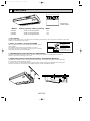
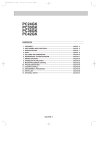
PCH24GK
PCH30GK
PCH36GK
PCH42GK
CONTENTS
1. FEATURES ·····································································································OC277- 2
2. PART NAMES AND FUNCTIONS··································································OC277- 4
3. SPECIFICATIONS ··························································································OC277- 7
4. DATA···············································································································OC277- 8
5. OUTLINES AND DIMENSIONS ·····································································OC277-19
6. REFRIGERANT SYSTEM DIAGRAM ····························································OC277-21
7. WIRING DIAGRAM·························································································OC277-22
8. OPERATION FLOW-CHART··········································································OC277-23
9. MICROPROCESSOR CONTROL ··································································OC277-27
10. TROUBLESHOOTING····················································································OC277-43
11. SYSTEM CONTROL ·······················································································OC277-50
12. DISASSEMBLY PROCEDURE·······································································OC277-55
13. PARTS LIST····································································································OC277-60
14. OPTIONAL PARTS ·························································································OC277-67
OC277-1
OC277--1.qxp
1
01.12.14 13:01
Page 2
FEATURES
SWING
TIMER OFF TIMER CLOCK AUTO AUTO
CHECK SET TEMP.
FAN
START STOP SPEED
FILTER
AUTO
RETURN
CHECK MODE
TEST RUN
Microprocessor
Remote controller
Indoor unit
Models
Cooling capacity / Heating capacity
PCH24GK
PCH30GK
PCH36GK
PCH42GK
24,000
30,000
35,400
42,000
/
/
/
/
27,000
33,000
38,000
45,000
(35,500)
(42,500)
(47,500)
(52,500)
Btu/h
Btu/h
Btu/h
Btu/h
SEER
10.3
10.0
10.3
10.3
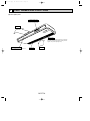
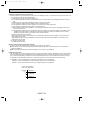
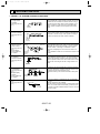
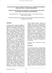
1. AIR OUTLET
New PCH series models have 1 air outlet (auto vane switching of horizontal air flow / down flow by switched by auto vane)
instead of 2 (horizontal,and down flows).
Protruding portion B
Unifies the air speed
with the vane.
2. EASY TO CLEAN ; FLOCKLESS VANE
With our original air current control mechanism, a flockless vane is
newly adapted.
The flockless vane prevents the condensation on the vane.
By changing the vane to the flockless type, the unit can be cleaned
much easier with mild household detergent.
B
Flockless vane
A
Air outlet
Protruding portion A
Sending the air to the upper
area of the vane
Prevents the air comes from
cntering from outside the unit
3. NEW MATERIALS FOR BETTER OIL RESISTANCE
We have changed the materials of grill, filer, fan and fan casing from ABS to P.P. (polypropylene) for better oil
resistance. As a result, oil crazing is cut in half.
4. SIMPLIFIED INSTALLATION WORK (DIRECT SUSPENDING METHOD)
Simplified the installation work by changing the suspending method to the direct suspending method (suspending
the unit directly from the suspension fixture).
In this way, the unit can be attached to the suspension fixture without removing the installation parts off (Only the
side cover is removed). This method is much simpler than the “One-time installation method”.
OC277-2
OC277--1.qxp
01.12.14 13:01
Page 3
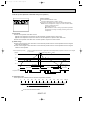
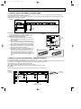
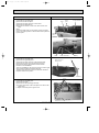
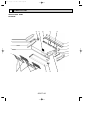
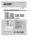
5. IMPROVING EFFICIENCY OF PIPING WORK
1 Removed the knockout work by separating the piping
space from the air outlet for efficiency of the piping work.
2 Improved the flexibility by making it possible for
drainage pipe to exit not only from the right side
back but also from the left side back.
Side panel
Back panel
Rubber plug
Drain pan
G L
open
G
D
L
U-cut
Insulation cover
(attached)
open
D
L : Liquid pipe
G : Gas pipe
D : Drain pipe
w Knockout work is needed for the top part. When optional drain-up machine is installed, the refrigerant pipe
exits out from the top.
Joint coupliy
(attached)
Insulation
cover
Drain pipe
(purchased locally)
Band
(attached)
w Please move the rubber plug for the unit to the right joint
when drainage pipe exits from the left side.
6. EASY MAINTENANCE ; NO MAINTENANCE NECESSARY FOR 2500 HOURS
The new long-life air filter can be used continuously 2500 hours without maintenance (at general office situation).
7. STABLE COOLING EVEN AT OUTDOOR TEMPERATURES AS LOW AS 23˚F MAKES
YEAR-ROUND AIR-CONDITIONING POSSIBLE
The microprocessor automatically adjusts fan speed in accordance with outdoor temperature to maintain the coolant at an
even condensing temperature. The result is smooth, efficient cooling even when temperatures outdoors drop as low as 23˚F.
This makes the unit ideal for a wide range of specialised cooling needs, such as rooms with many office machines or computers and areas subject to strong sunlight.
OC277-3
OC277--1.qxp
2
01.12.14 13:01
Page 4
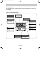
PART NAMES AND FUNCTIONS
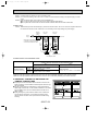
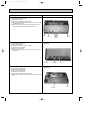
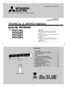
● Indoor (Main) Unit
Left/right guide vanes
Change the direction of airflow
from the horizontal blower.
Air outlet
Long-life fillter
Removes dust and foreigh matter from air coming in
through the grille (Recommended cleaning interval :
Approx, every 2,500 operating hours)
Up/down guide vanes
Change the direction of airflow from the
vartical blower.
Air intake
Intake grille
OC277-4
OC277--1.qxp
01.12.14 13:01
Page 5
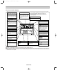
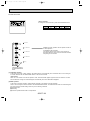
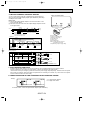
Remote controller
Once the controls are set, the same operation mode can be repeated by simply pressing the
ON / OFF button.
Remote controller operation buttons
CLOCK/TIMER button
TIMER ON/OFF button
This switches between continuous
operation and the timer operation.
This sets or switches the current
time,start time and stop time.
FAN SPEED button
OPERATION MODE
button
This sets the ventilation fan speed.
ON/OFF button
Press this button to switch the cooling, electronic dry (Dehumidify),
automatic and heating modes.
This switches between the operation and stop modes each time it is
press. The lamp on this button
lights during operation.
F
DRY COOL TIMER OFF TIMER CLOCK AUTO AUTO
AUTO
CHECK SET TEMP.
START STOP FAN
SPEED
HEAT
SET TEMPERATURE
button
This sets the room temperature.
The temperature setting can be performed in 2˚F units.
Setting range :
Cooling 65˚F to 87˚F
Heating 61˚F to 83˚F
AIR DISCHARGE
button
AUTO
RETURN
This adjusts the vertical angle of the
ventilation.
MODE
TIMER ON/OFF CLOCK/TIMER FAN SPEED AIR DISCHARGE FILTER
AIR SWEEP
SET TEMP.
TIMER SET
CHECK
TEST RUN
REMOTE CONTROLLER
FILTER button
This resets the filter service indication display.
AIR SWEEP button
CHECK-TEST RUN button
This switches the horizontal fan
motion (Swing louver) ON and OFF.
Only press this button to perform an
inspection check or test operation.
Do not use it for normal operation.
OC277-5
OC277--1.qxp
01.12.14 13:01
Page 6
Remote controller display
CENTRALLY
CONTROLLED display
This indicates when the unit is controlled by optional features such as
central control type remote controller.
In this display example on the bottom left, a condition where all display lamps light is shown for
explanation purposes although this differs from
actual operation.
CLOCK display
The current time , start time and stop
time can be displayed in ten second
intervals by pressing the time switch
button. The start time or stop time is
always displayed during the timer
operation.
AIR DISCHARGE display
This displays the air direction.
TIMER
display
FAN SPEED display
This indicates when the continuous
operation and time operation modes
are set.
It also display the time for the timer
operation at the same time as when
it is set.
The selected fan speed is displayed.
F
F
OPERATION MODE display
DRY COOL TIMER OFF TIMER CLOCK AUTO AUTO
AUTO
CHECK SET TEMP.
START STOP FAN
SPEED
HEAT
AUTO
RETURN
This indicates the operation mode.
MODE
TIMER ON/OFF CLOCK/TIMER FAN SPEED AIR DISCHARGE FILTER
STANDBY display
This indicates when the standby
mode is set from the time the heat
operation starts until the heating air
is discharged.
AIR SWEEP
SET TEMP.
TIMER SET
TEST RUN
This indicates when a malfunction
has occurred in the unit which should
be checked.
Operation lamp
REMOTE CONTROLLER
This lamp lights during operation,
goes off when the unit stops and
flashes when a malfunction occurs.
CHECK MODE
TEST RUN
This indicates when the defrost operation is performed.
display
The temperature of the return air is
displayed during operation. The display range is 47°F to 97°F. The display flashes 47°F when the actual
temperature is less than 47°F and
flashes 97°F when the actual temperature is greater than 97°F.
CHECK
DEFROST display
CHECK
display
display
This display lights in the check mode
or when a test operation is performed.
F display
This displays the selected setting
temperature.
display
FILTER
This lamp lights when electricity is
supplied to the unit.
display
This lamp lights when the filter needs
to be cleaned.
Caution
● Only the
display lights when the unit is stopped and power supplied to the unit.
● When power is turned ON for the first time the (CENTRAL CTRL) display appears to go off momentarily but this is not a malfunction.
● When the central control remote control unit, which is sold separately, is used the ON-OFF button,OPERATION MODE button and SET
TEMP. button do not operate.
OC277-6
OC277--1.qxp
01.12.14 13:01
3
Page 7
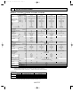
SPECIFICATIONS
MODELS : PCH24GK, PCH30GK, PCH36GK, PCH42GK
Model
Item
Capacity
Cooling *1
Heating *1
Heating *2
Moisture removal
Power
Consumption
EER
SEER
HSPF
COP
Cooling *1
Heating *1
Heating *2
*1
Btu/h
Btu/h
Btu/h
Pints/h
kW
kW
kW
*1
*2
INDOOR UNIT MODELS
External finish
V,phase,Hz
Power supply
A
Max.fuse size (time delay)
A
Min.ampacity
F.L.A.
Fan motor
A(kW)
Booster heater
CFM
Dry
Airflow Hi-Lo
CFM
Wet
dB
Sound level Hi-Lo
in.
Unit drain pipe O.D. (On a local side)
in.
W
in.
D
Dimensions
in.
H
lb
Weight
OUTDOOR UNIT MODELS
External finish
V,phase,Hz
Power supply
A
Max.fuse size (time delay)
A
Min.ampacity
F.L.A.
Fan motor
Model (type)
R.L.A.
Compressor
L.R.A.
A(W)
Crankcase heater
Refrigerant control
Defrost method
dB
Sound level
in.
W
in.
D
Dimensions
in.
H
lb
Weight
REMOTE CONTROLLER
Control voltage (by built-in transformer)
REFRIGERANT PIPING
in.
Liquid
Pipe size
in.
Gas
Indoors
Connection
Outdoors
method
Height difference ft
Between the indoor
ft
Piping length
& outdoor units
PCH30GK
PCH24GK
PCH36GK
PCH42GK
35,400
30,000
42,000
38,000[45,500/47,500]
33,000[40,500/42,500]
45,000[52,500/54,500]
21,000[28,500/30,500]
20,000[27,500/29,500]
23,800[31,300/33,300]
6.3
4.3
10.3
3.60
3.23
4.10
3.32[5.57/6.08]
3.00[5.25/5.76]
3.76[6.01/6.52]
2.63[4.88/5.39]
2.58[4.83/5.34]
3.00/[5.25/5.76]
9.8
9.3
10.5
10.3
10.0
10.3
7.0
7.0
7.2
3.4
3.2
3.4
2.3
2.3
2.3
PCH36GK
PCH30GK
PCH42GK
Munsell 0.70Y 8.59/0.97
208/230,1,60
25
25
20
25
17
17
15
17
1.3
1.3
1.1
1.3
10.8/12.0<2.3/2.8>
10.8/12.0<2.3/2.8>
9.8/10.8<2.0/2.5>
10.8/12.0<2.3/2.8>
1,240-990
880-710
1,130-880
810-640
51-45
51-45
48-43
51-45
1
1
1
1
63-3/4
51-9/16
26-3/4
26-3/4
10-5/8
10-5/8
101
87
106
PUH36EK1
PUH30EK
PUH-24EK
PUH42EK7
Munsell 5Y 7/1
208/230,1,60
30
20
40
30
20
16
28
22
0.75+0.75
0.65+0.65
0.8+0.8
0.75+0.75
NH41NAD
NH33NBD
ZR42K3PFV
NH47NAD
14.0
11.5
20.4
17.5
73
54
109
87
0.16/0.17<33/39>
0.16/0.17<33/39>
0.16/0.17<33/39>
0.16/0.17<33/39>
Capillary tube
Reverse cycle
55
55
56
55
34-1/4
38-3/16
11-5/8
13-9/16
49-9/16
49-9/16
245
202
268
246
With indoor unit
Indoor unit-remote controller: DC12V. Indoor unit-outdoor unit: DC12V
Not supplied (optional parts)
3/8
1/2
3/4
5/8
7/8
Flared
Flared
164
165
24,000
27,000[34,000/35,500]
14,800[21,800/23,300]
4.6
2.51
2.46[4.49/4.94]
1.95[3.98/4.43]
9.6
10.3
6.8
3.2
2.2
PCH24GK
NOTES : *1.Rating conditions (cooling)-indoor : D.B. 80˚F, W.B. 67˚F outdoor : D.B. 95˚F, W.B. 75˚F.
(heating)-indoor: D.B. 70˚F, W.B. 60˚F outdoor : D.B. 47˚F, W.B. 43˚F.
*2.Rating conditions (heating)-indoor : D.B. 70˚F, W.B. 60˚F outdoor : D.B. 17˚F, W.B. 15˚F.
*3.Heating capacity and power consumption in [ ] includes booster heater operation at 208/230V.
Operating range
Indoor intake air temperature
Outdoor intake air temperature
Maximum
D.B. 95˚F, W.B. 71˚F
D.B. 115˚F
Cooling
Minimum
D.B. 67˚F, W.B. 57˚F
D.B. 0˚F *
Maximum
D.B. 80˚F, W.B. 67˚F
D.B. 75˚F, W.B. 65˚F
Heating
Minimum
D.B. 70˚F, W.B. 68˚F
D.B. 17˚F, W.B.15˚F
In case of the wind baffle is installed.
*
(In case of the wind baffle is not installed, the minimum temperature will be D.B. 23˚F.)
OC277-7
OC277--1.qxp
01.12.14 13:01
4
Page 8
DATA
MODELS : PCH24GK, PCH30GK, PCH36GK, PCH42GK
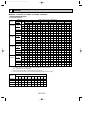
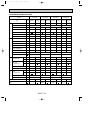
1. PERFORMANCE DATA
1) COOLING CAPACITY
Models
PCH24GK
Indoor air
Airflow I.W.B.
(CFM)
(˚F)
B.F
71
810
67
0.10
63
Outdoor intake air D.B. temperature (˚F)
65
75
85
95
105
115
TC SHC TPC TC SHC TPC TC SHC TPC TC SHC TPC TC SHC TPC TC SHC TPC
28.5 18.6 2.08 27.9 18.2 2.19 27.0 17.6 2.35 25.8 16.8 2.58 24.6 16.0 2.81 23.5 15.3 3.01
26.8 21.1 2.04 26.0 20.6 2.14 25.2 19.9 2.30 24.0 19.0 2.51 22.8 18.0 2.72 21.7 17.2 2.90
25.1 23.1 2.00 24.3 22.4 2.09 23.5 21.6 2.25 22.4 20.6 2.44 21.2 19.5 2.64 20.1 18.6 2.81
D.B.75°F (50%RH) 62.5 24.8 20.6 1.99 24.1 20.0 2.09 23.2 19.3 2.24 22.1 18.4 2.44 21.0 17.4 2.63 19.9 16.6 2.80
PCH30GK
D.B.72°F (50%RH)
60
23.8 19.8 1.97 23.1 19.2 2.06 22.3 18.5 2.21 21.2 17.6 2.40 20.1 16.7 2.59 19.1 15.8 2.75
D.B.70°F (50%RH)
59
23.4 19.4 1.96 22.7 18.7 2.05 21.9 18.1 2.19 20.8 17.2 2.38 19.7 16.3 2.57 18.7 15.4 2.73
71
35.7 25.0 2.68 34.9 24.5 2.81 33.8 23.7 3.03 32.3 22.7 3.32 30.7 21.6 3.62 29.3 20.6 3.88
67
33.4 28.1 2.63 32.6 27.3 2.75 31.5 26.4 2.96 30.0 25.2 3.23 28.5 23.9 3.50 27.1 22.8 3.73
63
31.3 30.4 2.57 30.4 29.5 2.69 29.3 28.5 2.89 27.9 27.2 3.15 26.5 25.7 3.40 25.2 24.5 3.62
1,130
0.08
D.B.75°F (50%RH) 62.5 31.0 27.4 2.57 30.1 26.6 2.69 29.1 25.6 2.88 27.7 24.4 3.13 26.2 23.1 3.39 24.9 22.0 3.60
PCH36GK
D.B.72°F (50%RH)
60
29.8 26.2 2.53 28.9 25.4 2.65 27.9 24.5 2.84 26.5 23.3 3.09 25.1 22.1 3.33 23.8 21.0 3.54
D.B.70°F (50%RH)
59
29.3 25.7 2.52 28.4 24.8 2.64 27.4 24.0 2.82 26.0 22.8 3.06 24.6 21.5 3.31 23.3 20.4 3.51
71
42.1 27.9 2.99 41.2 27.3 3.14 39.9 26.4 3.38 38.1 25.2 3.70 36.2 24.0 4.03 34.6 22.9 4.32
67
39.5 31.6 2.93 38.4 30.7 3.07 37.1 29.7 3.30 35.4 28.3 3.60 33.6 26.9 3.91 32.0 25.6 4.16
63
37.0 34.4 2.87 35.9 33.4 3.00 34.6 32.3 3.22 33.0 30.7 3.51 31.2 29.1 3.79 29.7 27.7 4.03
1,130
0.01
D.B.75°F (50%RH) 62.5 36.6 30.8 2.86 35.5 29.9 2.99 34.3 28.9 3.21 32.7 27.5 3.49 30.9 26.0 3.78 29.4 24.8 4.02
PCH42GK
D.B.72°F (50%RH)
60
35.2 29.5 2.82 34.1 28.6 2.95 32.9 27.6 3.16 31.3 26.3 3.44 29.6 24.9 3.72 28.1 23.6 3.95
D.B.70°F (50%RH)
59
34.6 28.9 2.81 33.5 28.0 2.94 32.3 27.0 3.14 30.7 25.7 3.41 29.0 24.3 3.69 27.5 23.0 3.91
71
50.0 29.6 3.41 48.9 28.9 3.57 47.3 28.0 3.85 45.2 26.8 4.21 43.0 25.4 4.59 41.1 24.3 4.92
67
46.8 34.2 3.34 45.6 33.3 3.49 44.0 32.1 3.76 42.0 30.7 4.10 39.9 29.1 4.45 38.0 27.7 4.74
63
43.8 37.8 3.27 42.6 36.7 3.42 41.1 35.4 3.67 39.1 33.7 3.99 37.1 31.9 4.32 35.2 30.4 4.59
1,130
0.04
D.B.75°F (50%RH) 62.5 43.4 33.5 3.26 42.1 32.5 3.41 40.7 31.4 3.66 38.7 29.9 3.98 36.7 28.3 4.30 34.9 26.9 4.58
D.B.72°F (50%RH)
60
41.7 32.1 3.22 40.4 31.1 3.37 39.0 30.0 3.60 37.1 28.6 3.92 35.1 27.0 4.23 33.3 25.7 4.50
D.B.70°F (50%RH)
59
41.0 31.4 3.20 39.7 30.4 3.35 38.3 29.3 3.58 36.4 27.9 3.89 34.4 26.4 4.20 32.7 25.0 4.46
Notes 1. B.F : Bypass Factor, I.W.B. : Intake air wet-bulb temperature
TC : Total Capacity (x103 Btu/h), SHC : Sensible Heat Capacity (x103 Btu/h)
TPC : Total Power Consumption (kW)
2. SHC is based on D.B. 80˚F of indoor intake air temperature.
3. Cooling capacity correction factors and Refrigerant piping length (one way) range.
Refrigerant piping length (one way)
MODEL
25ft
40ft
55ft
70ft
85ft 100ft 115ft 130ft 150ft 164ft
PCH24GK
1.0 0.981 0.968 0.952 0.940 0.925 0.913 0.900 0.886 0.874
PCH30GK
1.0 0.981 0.986 0.952 0.940 0.925 0.913 0.900 0.886 0.874
PCH36GK
1.0 0.981 0.968 0.952 0.940 0.925 0.913 0.900 0.886 0.874
PCH42GK
1.0 0.975 0.955 0.935 0.918 0.900 0.884 0.869 0.855 0.840
OC277-8
OC277--1.qxp
01.12.14 13:01
Page 9
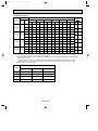
2) HEATING CAPACITY
Models
PCH24GK
Airflow I.D.B.
(CFM) (˚F)
880
PCH30GK 1,240
PCH36GK 1,240
PCH42GK 1,240
Auxiliary heater
208V
230V
Outdoor intake air W.B. temperature(˚F)
Indoor air
15
25
35
45
55
65
CA
PC
CA
PC
CA
PC
CA
PC
CA
PC
CA
PC
CA
PC
75
17.8
1.91
20.4
2.11
23.9
2.37
27.1
2.60
31.3
2.89
35.0
3.15
6.8
2.0
70
18.2
1.84
20.9
2.04
24.4
2.29
27.7
2.50
31.8
2.78
35.6
3.03
65
18.6
1.77
21.4
1.96
25.0
2.20
28.2
2.41
32.5
2.67
36.3
2.91
8.5
2.5
75
21.8
2.32
25.0
2.57
29.2
2.89
33.1
3.17
38.2
3.53
42.8
3.84
7.5
2.2
70
22.2
2.25
25.5
2.48
29.9
2.79
33.8
3.05
38.9
3.39
43.5
3.69
65
22.8
2.16
26.1
2.39
30.5
2.68
34.5
2.93
39.7
3.26
44.3
3.55
9.6
2.8
75
25.0
2.57
28.7
2.85
33.7
3.20
38.1
3.51
44.0
3.91
49.3
4.25
7.5
2.2
70
25.6
2.49
29.4
2.75
34.4
3.08
38.9
3.38
44.8
3.76
50.0
4.09
65
26.2
2.39
30.1
2.64
35.2
2.96
39.8
3.25
45.7
3.61
51.0
3.93
9.6
2.8
75
29.7
2.91
34.0
3.23
39.9
3.63
45.2
3.98
52.1
4.42
58.4
4.81
7.5
2.2
70
30.3
2.82
34.8
3.11
40.7
3.49
46.1
3.83
53.0
4.25
59.3
4.63
65
31.1
2.71
35.6
2.99
41.6
3.36
47.1
3.68
54.1
4.09
60.4
4.45
9.6
2.8
Notes 1. I.D.B. : Intake air dry-bulb temperature
CA : Capacity (x103 Btu/h), PC : Power Consumption (kW)
2. When booster heater is "on", total capacity and total power consumption should be added the figures described in
booster heater column.
•Booster heater ON : When the set temperature is higher than the room temperature by more than 5.4 deg.
•Booster heater OFF : When the set temperature is higher than the room temperature by less than 3.6 deg.
3. Heating capacity correction factors.
Refrigerant piping length (one way)
Models
Less than 100ft
100~130ft
130~164ft
PCH24GK
1.00
0.995
0.990
PCH30GK
1.00
0.995
0.990
PCH36GK
1.00
0.995
0.990
PCH42GK
1.00
0.995
0.990
OC277-9
OC277--1.qxp
01.12.14 13:01
Page 10
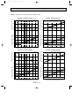
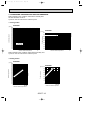
2. PERFORMANCE CURVE
NOTES : A point on the curve shows the reference point.
PCH24GK HEATING CAPACITY
SHF=0.79
36
Indoor intake air W.B. temperature ( F)
30
24
71
67
63
Total capacity (x10 3 Btu/h)
Total capacity (x10 3 Btu/h)
PCH24GK COOLING CAPACITY
Not include booster heater (2.5kW)
42
Indoor intake air D.B. temperature ( F)
65
70
75
36
30
24
18
71
67
63
3.0
2.5
2.0
1.5
32 35
Indoor intake air W.B. temperature ( F)
45
55
65(67) 75
85
95
105
Total power consumption (kW)
Total power consumption (kW)
18
75
70
65
3.0
2.5
2.0
Indoor intake air D.B. temperature ( F)
1.5
115
15
Outdoor intake air DB temperature ( F)
SHF=0.84
42
65
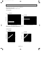
PCH30GK HEATING CAPACITY
Indoor intake air W.B. temperature ( F)
36
30
71
67
63
24
Total capacity (x10 3 Btu/h)
Total capacity (x10 3 Btu/h)
PCH30GK COOLING CAPACITY
25
35
45
55
Outdoor intake air WB temperature ( F)
Not include booster heater (2.8kW)
54
Indoor intake air D.B. temperature ( F)
42
65
70
75
30
18
4.0
71
67
63
3.5
3.0
2.5
Indoor intake air W.B. temperature ( F)
2.0
32 35
45
55
65(67) 75
85
95
105
115
Total power consumption (kW)
Total power consumption (kW)
4.0
75
70
65
3.5
3.0
2.5
Indoor intake air D.B. temperature ( F)
2.0
15
Outdoor intake air DB temperature ( F)
OC277-10
25
35
45
55
Outdoor intake air WB temperature ( F)
65
OC277--1.qxp
01.12.14 13:01
Page 11
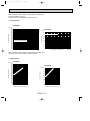
NOTES : A point on the curve shows the reference point.
PCH36GK HEATING CAPACITY
Indoor intake air W.B. temperature ( F)
42
36
71
67
63
30
4.5
71
67
63
4.0
3.5
3.0
2.5
32 35
Indoor intake air W.B. temperature ( F)
45
55
65(67) 75
85
95
105
Total capacity (x10 3 Btu/h)
SHF=0.80
48
Total power consumption (kW)
Total power consumption (kW)
Total capacity (x10 3 Btu/h)
PCH36GK COOLING CAPACITY
Not include booster heater (2.8kW)
54
Indoor intake air D.B. temperature ( F)
30
18
4.5
75
70
65
4.0
3.5
3.0
2.5
Indoor intake air D.B. temperature ( F)
115
15
Outdoor intake air DB temperature ( F)
25
35
45
55
Outdoor intake air WB temperature ( F)
65
PCH42GK HEATING CAPACITY
SHF=0.73
Indoor intake air W.B. temperature ( F)
48
42
71
Total capacity (x10 3 Btu/h)
Total capacity (x10 3 Btu/h)
PCH42GK COOLING CAPACITY
54
65
70
75
42
67
Not include booster heater (2.8kW)
66
Indoor intake air D.B. temperature ( F)
65
70
75
54
42
30
36
Total power consumption (kW)
71
67
63
4.5
4.0
3.5
3.0
Indoor intake air W.B. temperature ( F)
32 35
45
55
65(67) 75
85
95
105
115
Outdoor intake air DB temperature ( F)
OC277-11
Total power consumption (kW)
63
5.0
5.0
75
70
65
4.5
4.0
3.5
3.0
Indoor intake air D.B. temperature ( F)
15
25
35
45
55
Outdoor intake air WB temperature ( F)
65
OC277--1.qxp
01.12.14 13:01
Page 12
3. CONDENSING PRESSURE AND SUCTION PRESSURE
Data is based on the condition under indoor humidity 50%.
Air flow should be set at HI.
A point on the curve shows the reference point.
< Cooling mode>
PCH24GK
PCH24GK
Suction pressure
86 (psi.G)
80
100
75
70
90
Condensing pressure
(psi.G)
360
350
340
330
320
310
300
290
280
270
260
250
240
230
220
210
200
190
180
170
160
150
Indoor D.B.
temperature( F)
86
80
75
70
Indoor D.B. temperature( F)
80
70
60
50
40
30
30
40
50
60
70
80
90
Outdoor ambient temperature
100
20
110
D.B.( F)
30
40
50
60
70
80
90
Outdoor ambient temperature
Data is based on the condition under outdoor humidity 75%.
A point on the curve shows the reference point.
< Heating mode>
PCH24GK
PCH24GK
ur
e(
F)
(psi.G) 80
.t
60
In
do
or
D.
B
50
40
75
70
65
em
pe
ra
t
70
Suction pressure
Condensing pressure
(psi.G)
350
340
330
320
310
300
)
290
(F
280
re
u
t
270
ra
pe
260
m
e
250
.t
75
.B
240
D
70
r
o
230
65
do
n
220 I
210
200
190
180
170
160
150
20 25 30 35 40 45 50 55 60 65 70
D.B.( F)
Outdoor ambient temperature
30
20
10
20 25 30 35 40 45 50 55 60 65 70
D.B.( F)
Outdoor ambient temperature
OC277-12
100
110
D.B.( F)
OC277--1.qxp
01.12.14 13:01
Page 13
Data is based on the condition under indoor humidity 50%.
Air flow should be set at HI.
A point on the curve shows the reference point.
< Cooling mode>
PCH30GK
PCH30GK
(psi.G)
110
86
80
75
70
86
80
75
70
100
Suction pressure
Condensing pressure
(psi.G)
350
340
330
320
310
300
290
280
270
260
250
240
230
220
210
200 Indoor D.B. temperature( F)
190
180
170
160
150
30
40
50
60
70
80
90
Outdoor ambient temperature
90
Indoor D.B. temperature( F)
80
70
60
50
40
100
30
110
D.B.( F)
30
40
50
60
70
80
90
Outdoor ambient temperature
Data is based on the condition under outdoor humidity 75%.
A point on the curve shows the reference point.
< Heating mode>
PCH30GK
PCH30GK
(F
)
(psi.G) 80
pe
ra
tu
re
70
.B
rD
In
do
o
30
.t
50
40
75
70
65
em
60
Suction pressure
Condensing pressure
(psi.G)
340
330
320
310
300
290
)
280
(F
re
270
u
t
260
ra
pe
75
250
em
70
240
.t
B
65
230
D.
r
o
220
o
d
210 In
200
190
180
170
160
150
140
20 25 30 35 40 45 50 55 60 65 70
D.B.( F)
Outdoor ambient temperature
20
10
20 25 30 35 40 45 50 55 60 65 70
D.B.( F)
Outdoor ambient temperature
OC277-13
100
110
D.B.( F)
OC277--1.qxp
01.12.14 13:01
Page 14
Data is based on the condition under indoor humidity 50%.
Air flow should be set at HI.
A point on the curve shows the reference point.
< Cooling mode>
PCH36GK
PCH36GK
86
80
75
70
(psi.G)
90
86
80
75
70
Indoor D.B. temperature( F)
80
Suction pressure
Condensing pressure
(psi.G)
350
340
330
320
310
300
290
280
270
260
250
240
230
220
210
200
190
180
170
160
150
Indoor D.B. temperature( F)
70
60
50
40
30
20
30
40
50
60
70
80
90
Outdoor ambient temperature
100
30
110
D.B.( F)
40
50
60
70
80
90
Outdoor ambient temperature
Data is based on the condition under outdoor humidity 75%.
A point on the curve shows the reference point.
< Heating mode>
PCH36GK
ra
tu
re
(°F
)
(psi.G) 80
em
pe
70
.B
do
or
D
40
In
50
75
70
65
.t
60
Suction pressure
Condensing pressure
PCH36GK
(psi.G)
350
340
330
320
)
310
(°F
300
re
u
t
290
ra
pe
280
m
e
.t
270
.B
D
260
75
or
250
70
do
240 In
65
230
220
210
200
190
180
170
160
150
20 25 30 35 40 45 50 55 60 65 70
D.B.(°F)
Outdoor ambient temperature
30
20
10
20 25 30 35 40 45 50 55 60 65 70
D.B.(°F)
Outdoor ambient temperature
OC277-14
100
110
D.B.( F)
OC277--1.qxp
01.12.14 13:02
Page 15
Data is based on the condition under indoor humidity 50%.
Air flow should be set at HI.
A point on the curve shows the reference point.
< Cooling mode>
PCH42GK
86
80
75
70
PCH42GK
(psi.G)
90
86
80
75
70
Indoor D.B. temperature(°F)
80
Suction pressure
Condensing pressure
(psi.G)
350
340
330
320
310
300
290
280
270
260
250
240
230
220
210
200
190
180
170
160
150
Indoor D.B. temperature(°F)
70
60
50
40
30
20
30
40
50
60
70
80
90
Outdoor ambient temperature
100
30
110
D.B.(°F)
40
50
60
70
80
90
Outdoor ambient temperature
Data is based on the condition under outdoor humidity 75%.
A point on the curve shows the reference point.
< Heating mode>
PCH42GK
(°F
)
(psi.G) 80
pe
ra
tu
re
70
75
70
65
em
60
40
30
rD
.B
.t
50
In
do
o
Suction pressure
Condensing pressure
PCH42GK
(psi.G)
350
340
330
320
)
310
(°F
300
re
u
t
290
ra
pe
280
m
e
270
.t
75
.B
D
260
70
r
o
250
o
65
d
240 In
230
220
210
200
190
180
170
160
150
20 25 30 35 40 45 50 55 60 65 70
D.B.(°F)
Outdoor ambient temperature
20
10
20 25 30 35 40 45 50 55 60 65 70
D.B.(°F)
Outdoor ambient temperature
OC277-15
100
110
D.B.(°F)
OC277--1.qxp
01.12.14 13:02
Page 16
4. STANDARD OPERATION DATA
Models
PCH24GK
Heating
Cooling
Heating
Cooling
Heating
Cooling
Heating
Voltage
V
208/230
208/230
208/230
208/230
208/230
208/230
208/230
208/230
Frequency
Hz
Total input
kW
2.51
2.46
3.23
3.00
3.60
3.32
4.10
3.76
Indoor fan current
A
1.1
1.1
1.3
1.3
1.3
1.3
1.3
1.3
Booster heater current
A
Outdoor fan current
A
0.65+0.65 0.65+0.65 0.75+0.75 0.75+0.75 0.75+0.75 0.75+0.75 0.8+0.8
Comp. current
A
11.3/10.4 10.9/10.2 14.5/13.3 13.4/12.5 16.51/15.1 15.0/14.0 18.8/17.3 17.2/16.0
Electrical circuit
Refrigerant circuit
60
60
9.8/10.8
60
10.8/12.0
60
10.8/12.0
10.8/12.0
0.8+0.8
Condensing pressure
psi.G
242
227
250
221
253
225
272
246
Suction pressure
psi.G
82
62
85
59
82
62
76
59
Discharge temperature
˚F
161
155
164
155
164
155
173
153
Condensing temperature
˚F
115
111
115
108
117
109
122
115
Suction temperature
˚F
48
35
53
34
50
35
46
33
Comp.shell bottom temperature
˚F
144
132
156
145
153
138
119
87
Ref. pipe length
ft
25
25
25
25
9 lbs 15 oz
10 lbs 2 oz
10 lbs 9 oz
11 lbs 0 oz
D.B.
˚F
80
70
80
70
80
70
80
70
W.B.
˚F
67
60
67
60
67
60
67
60
D.B.
˚F
59
100
60
96
57
101
56
105
W.B.
˚F
58
Fan speed
r.p.m.
1,100
1,070
1,190
1,150
1,220
1,200
1,220
1,200
Airflow (High)
CFM
810
880
1,130
1,240
1,130
1,240
1,130
1,240
D.B.
˚F
95
47
95
47
95
47
95
47
W.B.
˚F
Intake
air temperature
Indoor side
PCH42GK
Cooling
Refrigerant charge
Outdoor side
PCH36GK
Unit
Item
Discharge
air temperature
Intake
air temperature
59
56
43
55
43
43
43
Fan speed upper/lower
r.p.m.
750/750
760/760
760/760
840/840
Airflow
CFM
3,170
3,350
3,350
3,530
Capacity
SHF
PCH30GK
Btu/h
24,000
0.79
27,000
30,000
0.84
OC277-16
33,000
35,400
0.80
38,000
42,000
0.73
45,000
OC277--1.qxp
01.12.14 13:02
Page 17
5. OPERATING RANGE
1) POWER SUPPLY
Min.
198V
1 Phase 60Hz 208/230V
Guaranteed voltage range
208V
Max.
253V
230V
2) OPERATION
Air intake temperature
Outdoor
Indoor
Function
Condition
D.B.(˚F)
W.B.(˚F)
D.B.(˚F)
W.B.(˚F)
Standard temperature
80
67
95
75
Maximum temperature
95
71
115
—
Minimum temperature
67
57
23
—
Maximum humidity
80
75
80
75
Standard temperature
70
60
47
43
Maximum temperature
80
67
75
65
Minimum temperature
70
60
17
15
Cooling
Heating
6. OUTLET AIR SPEED AND COVERAGE RANGE
Model
Airflow
(CFM)
Air speed
(ft/sec)
Coverage
range(ft)
PCH24GK
880
13.5
40
PCH30GK
1,240
14.8
50
PCH36GK
1,240
14.8
50
PCH42GK
1,240
14.8
50
The air coverage range is the value up to the position
where the air speed is 0.8ft/sec. when air is blown out
horizontally from the unit at the High notch position.
The coverage range should be used only as a general
guideline since it varies according to the size of the
room and furniture installed inside the room.
7. ADDITIONAL REFRIGERANT CHARGE (R22(oz))
Refrigerant piping length (one way)
Outdoor unit
precharged
(up to 100ft)
25ft
40ft
55ft
70ft
85ft
PCH24GK
9 lbs 15 oz
0
0
0
0
0
0
2
4
7
9
PCH30GK
10 lbs 2 oz
0
0
0
0
0
0
5
10
16
20
PCH36GK
10 lbs 9 oz
0
0
0
0
0
0
5
10
16
20
PCH42GK
11 lbs 0 oz
0
0
0
0
0
0
5
10
16
20
Model
100ft 115ft 130ft 150ft 164ft
OC277-17
01.12.14 13:02
Page 18
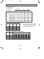
8. NOISE CRITERION CURVES
NOTCH SPL(db)
PCH24GK
OCTAVE BAND SOUND PRESSURE LEVEL, dB re 0.0002 MICRO BAR
Hi
Lo
LINE
48
42
90
80
70
NC-70
60
NC-60
50
NC-50
40
NC-40
30
NC-30
20
10
APPROXIMATE
THRESHOLD OF
HEARING FOR
CONTINUOUS
NOISE
63
NC-20
about 4.62ft
NOTCH SPL(db) LINE
Hi
51
Lo
45
90
80
70
NC-70
60
NC-60
50
NC-50
40
NC-40
30
NC-30
20
10
APPROXIMATE
THRESHOLD OF
HEARING FOR
CONTINUOUS
NOISE
125 250 500 1000 2000 4000 8000
BAND CENTER FREQUENCIES, Hz
ceiling
3.3ft
3.3ft
PCH30GK
PCH36GK
PCH42GK
OCTAVE BAND SOUND PRESSURE LEVEL, dB re 0.0002 MICRO BAR
OC277--1.qxp
unit
MICROPHONE
Ambient temperature 80˚F
Test conditions are based on JIS Z8731
OC277-18
63
NC-20
125 250 500 1000 2000 4000 8000
BAND CENTER FREQUENCIES, Hz
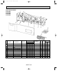
When electrical box
is pulled down
2
8/32~9/32
9
7
Electrical box
20-11/16
9-1/32
2-3/4
48-5/8
7-7/8
Ceiling
6
Electrical box [FRONT VIEW]
3-11/16
6-5/16
3
9-7/16
1-5/8
1-3/4
5-15/16
5-1/2
1-1/2
2
27-1/16
13
1-1/2
1
6-3/4
5-7/16
10-3/8
5
7-9/16
Air intake
48-7/8
48-3/8
51-9/16
47-13/16
6-5/16
(Suspension bolt pitch)
8
3-9/16
10
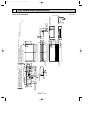
Refrigerant-pipe connection(liquid pipe side/flared connection)
Knock out hole for wiring arrangement
Knock out hole for left drain pipe arrangement
Knock out hole for upper drain pipe arrangement
Knock out hole for fresh air intake
Air outlet
3-3/8
4
5
6
7
8
9
1/16
9-5/16
1-3/4
3-1/8
2-3/16
3-25/32
3-3/16
12-5/8
8-5/32
26-3/4
Drainage pipe connection(On a local side 1-1/32IN.O.D.)
Drainage pipe connection(for the left arrangement)
Knock out hole for left drain-piping arrangement
Refrigerant-pipe connection(gas pipe side/flared connection)
10-5/8
1
2
3
4
8-9/16
10-5/8
or more
5/8
3-7/16
51-9/16
Ceiling
Rear wall
9-5/8
7-13/16
7-3/16
11-13/16
or more
(inch)
Less than
9-7/8
Allowing clearances
(3/8F)liquid
(5/8F)gas
(Drainage)
NOTES.
1.Use W3/8 screw for anchor bolt.
Less than 26-3/4
OC277-19
19-7/8
Indoor unit PCH24GK
19-11/16 or more
5
(Gap to ceiling)
01.12.14 13:02
1/16
OC277--1.qxp
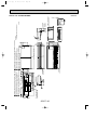
Page 19
OUTLINES AND DIMENSIONS
Unit:inch
9-7/16
1-5/8
Electrical box
When electrical box
is pulled down
3
7
9
9-1/32
2-3/4
2
5
5-7/16
1
8/32~9/32
4
27-1/16
13
Air intake
Air outlet
10-3/8
6-3/4
3-3/8
Electrical box
60-13/16
1-3/4
5-15/16
6
1-1/2
3-11/16
6-5/16
20-11/16
7-7/8
Ceiling
5-1/2
1-1/2
[FRONT VIEW]
7-9/16
1/16
9-5/16
1-3/4
60-7/8
60-7/16
63-3/4
60
(Suspension bolt pitch)
6-5/16
3-1/8
3-9/16
10-5/8
or more
5/8
3-7/16
63-3/4
Ceiling
Rear wall
9-5/8
7-13/16
7-3/16
11-13/16
or more
Less than
9-7/8
Allowing clearances
(1/2F)liquid
(3/4F)gus
(Drainage)
Refrigerant-pipe connection(liquid pipe side/flared connection)
NOTES.
Knock out hole for wiring arrangement
1.Use W3/8 screw for anchor bolt.
Knock out hole for left drain pipe arrangement
Knock out hole for upper drain pipe arrangement
(inch)
8
Knock out hole for fresh air intake
10
2
5
6
7
8
9
8-9/16
Drainage pipe connection(On a local side 1-1/32IN. O.D.)
Drainage pipe connection(for the left arrangement)
Knock out hole for left drain-piping arrangement
Refrigerant-pipe connection(gas pipe side/flared connection)
3-25/32
3-3/16
12-5/8
10-5/8
26-3/4
1
2
3
4
Less than 26-3/4
8-5/32
2-3/16
19-7/8
OC277-20
19-11/16 or more
Indoor unit PCH30/36/42GK
(Gap to ceiling)
01.12.14 13:02
1/16
OC277--1.qxp
Page 20
Unit:inch
OC277--1.qxp
01.12.14 13:02
Page 21
Unit : inch
Remote controller
3/32
5-1/8
23/32
SWING
TIMER OFF TIMER CLOCK AUTO AUTO
CHECK SET TEMP.
FAN
START STOP SPEED
FILTER
CHECK MODE
TEST RUN
4-3/4
AUTO
RETURN
3/4
6
REFRIGERANT SYSTEM DIAGRAM
PCH24GK
Refrigerant flow
Refrigerant pipe
(option)
{5/8"
(with heat insulator)
Strainer
Pipe temperature
thermistor / Liquid
(RT2)
Restrictor
valve
Distributor
Refrigerant pipe
(option)
{3/8"
(with heat insulator)
Capillary tube
({0.126O{0.071O15.7)
PCH30GK
PCH36GK
PCH42GK
Refrigerant pipe
(option)
{7/8" (PCH42GK)
{3/4" (PCH30/36GK)
(with heat insulator)
Strainer
Pipe temperature
thermistor / Liquid
(RT2)
Restrictor
valve
Distributor
Refrigerant pipe
(option)
{1/2"
(with heat insulator)
Capillary tube
PCH30GK ({0.157O{0.079O15.7)
PCH36GK ({0.157O{0.094O21.7)
PCH42GK ({0.157O{0.094O25.6)
OC277-21
HEATING
COOLING
OC277--1.qxp
01.12.14 13:02
7
Page 22
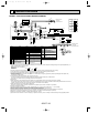
WIRING DIAGRAM
MODEL PCH24/30/36/42GK WIRING DIAGRAM
POWER
1 3 CNDK
(WHT)
1 3 5
FAN
(WHT)
POWER
1 3
CND
(RED)
SW9
ON
OFF
CENTRALLY
CONTROL
CN51
INTAKE
CN20
(RED)
1 2
6
MV
4
3
2
1
BZ
CNB
ON
OFF
ON
OFF
BLK
BLK
TRANSMISSION WIRES DC12V
3
2
1
BRN
ORN
YLW
TB4
R.B
3
2
1
TRANSMISSION WIRES
DC12V
TB3
OUTDOOR UNIT
RT2
H
FS1
SW18
OFF
ON
A01 B02
TB6
CN1
87654321
5 4 3 2 1
CN2
SW17
OFF
ON
FS2
3 2 1
88H1
RED 1 RED 5
WHT 2 BLU 5
3
3
TB2
L1
L2
RED
BLU
HEATER
CN24
1 2 (YLW)
8
8
88H1
88H2
7
7
26H
6 RED
GRY 5 RED
GRY
YLW
YLW
I.B
YLW
SYMBOL
NAME
W.B
WIRELESS REMOTE CONTROLLER BOARD(OPTION)
RU RECEIVING UNIT
BZ BUZZER
LED1 LED(RUN INDICATOR)
LED2 LED(HOT ADJUST)
TERMINAL BLOCK(INDOOR/OUTDOOR TRANSMISSION LINE)
TERMINAL BLOCK(REMOTE CONTROLLER
SW1 SWITCH(HEATING ON/OFF)
TRANSMISSION LINE)
SW2 SWITCH(COOLING ON/OFF)
HEATER
ROOM TEMP.THERMISTOR
(32°F/15k",77°F/5.4k" DETECT)
FS1,2 THERMAL FUSE<243°F/16A:24GK>
PIPE TEMP.THERMISTOR/LIQUID
THERMAL FUSE<230°F/16A:30,36,42GK>
(32°F/15k",77°F/5.4k" DETECT)
H
HEATER
REMOTE CONTROLLER BOARD
26H HEATER THERMAL SWITCH
CONNECTOR(PROGRAM TIMER)
88H1,2 HEATER CONTACTOR
CONNECTOR(REMOTE SWITCH)
SWITCH(ADDRESS SELECTOR)
SWITCH(FUNCTION SELECTOR)
TERMINAL BLOCK(REMOTE CONTROLLER
TRANSMISSION LINE)
NAME
CAPACITOR(FAN MOTOR)
FAN MOTOR
VANE MOTOR
TERMINAL BLOCK(POWER)
NOTES:
1.Since the indoor fan motor(MF)is connected with 230V power, using 208V power will require a setting change of the dip switch(SW8<I.B>) on
indoor controller board as shown in fig:*1.
fig:*1 Indoor fan motor(MF)for
208V.
SW8
ON
ON
OFF
ON
OFF
LED1 LED2 SW2 SW1
TB5
REMOCON
2
BLU
CN22 2
1
BLU
(BLU)
1
88H2
123456
ON
OFF
RU
87654321
NAME
SYMBOL
INDOOR POWER BOARD
C
INDOOR CONTROLLER BOARD MF
CONNECTOR(LOSSNAY)
MV
CONNECTOR(CENTRALLY CONTROL) TB2
FAN PHASE CONTROL
TB4
SWITCH(FUNCTION SELECTOR) TB5
SWITCH(ADDRESS SELECTOR)
SWITCH(EMERGENCY OPERATION) RT1
SWITCH(MODEL SELECTOR)
SWITCH(TWIN/TRIPLE SELECTOR) RT2
SWITCH(MODEL SELECTOR)
R.B
SWITCH(OPTION)
SWITCH(MODEL SELECTOR)
CN1
CN2
RELAY(FAN MOTOR)
SW17
FUSE(6A/250V)
SW18
VARISTOR
TB6
LED(DC12V POWER)
LED(DC5V POWER)
123
42GK
9
1 2
SYMBOL
P.B
I.B
CN2L
CN51
FC
SW1
SW2
SW3
SW5
SW6
SW7
SW8
SW9
X4
F1,F2
ZNR
LED1
LED2
123
36GK
6
WIRELESS
CN90
(WHT)
PIPE
OUT
CN21 LOSSNAY DOOR 3
(WHT) CN2L
CN30 2
1 2
(BLU) 1
RT1
123
W.B
REMOCON
POWER
CN40
(WHT)
12345
SW2 SW5 SW8
SW1
SW6 SW7
ON
OFF
123456 1234 123456 12345678910 1234 123
24GK
F1
ZNR
LED1 LED2
X4
SW3
ON
OFF
12
VANE
CN6V
(WHT)
SW7
123
30GK
1 2
CN2D
(WHT)
F2
X4
FC
MODELS
POWER SUPPLY
~(1PHASE)
AC208/230V 60Hz
GRN/YLW
RED
BLU
BLK
WHT
RED
WHT
BLK
C
RED
BLU
BLK
WHT
MF
1 2 3
I.B
TB2
L1
L2
GR
P.B
(AC208/230V)
(DC13.1V)
CNSK
(RED) TRANS CN2S
(WHT)
3
2
2
1
1
OFF
123456
2.Since the outdoor side electric wiring may change, be sure to check the outdoor unit electric wiring for servicing.
3.Indoor and outdoor connecting wires are made with polarities, make wiring matching terminal numbers.
4.Symbols used in wiring diagram above are,
:Connector, :Terminal block.
5.Emergency operation
If remote controller or microcomputer fails but there is no other trouble, emergency operation is possible by setting dip switch (SW3<I.B>)
on the indoor controller board.
6.Fasten terminal of the terminal board "TB4" equips lock system.
To remove the fasten terminal, pull it while pressing the protruding portion (locking lever) of the terminal.
Connection of the fasten terminal, protruding portion should face upward.
[Check items]
(1)Make sure that no other trouble exist in the outdoor unit. Trouble with the outdoor unit prevents emergency operation.
(If any trouble exists in the outdoor unit error code "P8" will be displayed on the remote controller and the trouble position will be shown on the
outdoor controller board LED. See electric wiring diagram of the outdoor unit for details.)
(2)Make sure that there is no trouble with the indoor fan.
Emergency operation will be continuous operation mode. (ON/OFF by the remote controller is not possible.)
[Emergency operation procedure]
(1)Set the dip switch (SW3<I.B>) on the indoor controller board to 1 on and 2 off for cooling and 1 · 2 on for heating.
(2)Turn on outdoor unit side circuit breaker, then indoor unit side circuit breaker.
(3)During emergency operation, indoor fan runs at high speed but automatic vane does not work.
(4)Thermostat will not function. Cold air blows out for defrosting during heating thus do not operate defrosting for a long time.
(5)Emergency cooling should be limited to 10 hours maximum. (The indoor unit heat exchanger may freeze.)
(6)After every emergency operation, set all dip switch (SW3<I.B>) to OFF.
(7)Movement of the vane does not work in emergency operation, therefore you have to slowly set them manually to the appropriate position.
OC277-22
POWER SUPPLY
~(1PHASE)
AC208/230V 60Hz
OC277--1.qxp
01.12.14 13:02
8
Page 23
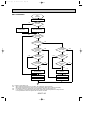
OPERATION FLOW-CHART
MAIN OPERATION
START
Power circuit
breaker
NO
YES
1
YES
Check SW
ON twice
NO
Operation SW
ON
NO
w 1
YES
YES
“OFF” timer
NO
NO
Set time
complete
“ON” timer
NO
YES
YES
YES
Set time
complete
w 2
NO
Trouble
NO
Remote controller
operation display
YES
STOP
Trouble STOP
PROTECTION DEVICE
SELF HOLD RELEASE
PROTECTION DEVICE
SELF HOLD
Operating mode
(COOL)
Remote controller
trouble display
YES
DRY operation
NO
Operating mode
(HEAT)
Indoor side
COOL operation
NO
Operating mode
(DRY)
w 3
Remote controller
indicator lamp OFF
YES
YES
HEAT operation
NO
w 4
w 6
Fan STOP
Operating mode
(FAN)
NO
Auto COOL/HEAT
operation
Auxiliary heater OFF
YES
w 7
FAN operation
Outdoor side
w 5
Compressor OFF
Fan STOP
Four-way valve OFF
w1 In addition, the centralised and remote control can be operated.
w2 The modes which indicate the sources of trouble are listed below.
● EO=Signal transmitting/receiving error
● P1=Room temperature thermistor malfunction
● P2=Indoor coil thermistor malfunction
● P4=Drain sensor malfunction
● P5=Drain over flow
● P6=Coil frost/overheat protection
● P7=System error
● P8=Outdoor unit trouble
w3 The CHECK switch will show if an error has occurred in the past.
w4 Fan runs on low speed for 1 minute in order to remove overheat air.
w5 The 3-minute (6 minutes … heating mode) time-delay functions after compressor stops.
w6 FAN or AUTO mode is selected by the indoor dip switch setting.
w7 In FAN mode, fan speed and vane operation depend on the remote controller setting. (Compressor is OFF.)
OC277-23
OC277--1.qxp
01.12.14 13:02
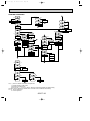
Page 24
COOLING OPERATION
COOL operation
Four-way valve/OFF
NO
Initial
COOLING
w 8
YES
Vane initial
setting
Vane
40 deg downward angle
60 deg downward angle
NO
NO
NO
Vane setting notch
YES
Fan speed
LOW
YES
Downward discharge
1 hour
YES
Vane horizontal
airflow
NO
w 9
YES
Compressor
thermostat
ON
NO
Allowance
cancel
NO YES
3-minute
time delay
YES
NO
6-minute
time delay
NO
3-minute
compressor operation
Allowance
period
NO
6 minute
time delay
NO
w 10
YES
Allowance set
YES
Coil frost
prevention
Coil frost protection
YES
NO
w 11
NO
Cooling area
NO
YES
10-minute
compressor operation
NO
YES
YES
Allowance cancel
Coil frost
protection
FAN speed
LOW
YES
NO
NO
16-minute
compressor operation
Indoor coil
temperature is
50°F or higher
YES
Indoor coil
temperature is
34°F or lower
YES
3-minute
time delay
NO
Compressor ON
1 min continue
YES
Coil frost
prevention
NO
FAN speed
LOW 5 min
elapse
NO
YES
Outdoor unit
trouble
Coil frost
prevention release
Compressor OFF
1
w8 When operation stops or changes to cooling or dry mode, the auto vane turns to a horizontal angle. If operation changes
during auto vane SWING, the auto vane will continue to swing.
w9 When operating TEST RUN, the thermostat will be continuously ON.
w10 After 3 minute compressor operation, if the indoor coil thermistor reads -59°F or below for 3 minutes, the compressor will
stop for 6 minutes.
w11 Cooling area : Indoor coil temperature is more than 9 degrees above the room temperature.
Heating area : Indoor coil temperature is more than 9 degrees below the room temperature.
FAN area : Indoor coil temperature is within 9 degrees either way of the room temperature.
OC277-24
OC277--1.qxp
01.12.14 13:02
Page 25
DRY OPERATION
DRY
operation
Four-way valve / OFF
NO
Initial dry
operation
w8
YES
Vane
setting notch
Vane initial setting
YES
Room temperature is
64°F or lower
w 12
NO
NO
During
compressor ON
YES
3-minute
compressor
operation
NO
NO
YES
NO
YES
3-minute
time delay
w9
Compressor &
thermostat ON
YES
Compressor &
thermostat
ON
w9
NO
YES
NO
Compressor ON
time completes
10-minute
compressor
OFF
YES
YES
10-minute compressor
OFF timer start
Compressor OFF
w 14
Fan STOP
w 13
Compressor ON
time set
Compressor ON
w 14
Fan speed LOW
1
w8 ~ 9 Refer to page OC277-24.
w12
When room temperature is 64°F or below, the compressor cannot operate.
When room temperature rises over 64°F, the compressor starts after a 3-minute time delay.
w13
Compressor ON time is decided by room temperature. Refer to page OC277-33.
w14
In dry operation, compressor ON makes the fan speed LOW and compressor OFF stops the fan.
It is not possible to set the fan speed with the remote controller
OC277-25
NO
OC277--1.qxp
01.12.14 13:02
Page 26
HEATING OPERATION
A
Heat operation
NO
Vane setting notch
w 11
w 15
Initial
HEATING
YES
Vane initial setting
YES
Heating area
NO
NO
Defrost
30 min. elaspe
YES
Outdoor unit trouble
NO
YES
Defrosting
NO
Four-way
valve ON
2
Indoor coil
NO
thermistor is 140°F
or higher
FAN speed NO
Low notch
YES
Airflow 10% up
FAN setting notch
1
YES
Hot adjust
in process
NO
YES
Compressor ON
NO
Compressor YES
w 9 thermostat ON
3 min.restart
prevention
Allowance cancel
NO Indoor piping
-5°F or lower
YES
Outdoor unit
trouble
3-minute
NO
Auxiliary heater
OFF
Defrost release
NO 10-minute
compressor
operation
YES
Allowance cancel
YES 6 min. restart
prevention
2 NO
Hot adjust start
FAN SPEED
very low
Compressor ON
FAN SPEED
Very low airflow
Compressor OFF
B
Indoor piping YES
131°F or lower
NO
NO Auxiliary heater NO
Auxiliary heater
ON
thermostat ON
YES
YES
NO
Auxiliary heater
Indoor piping
ON
140°F or higher
YES
Auxiliary heater
OFF
w 11
Heating
area
YES
A
FAN STOP
w 11
Airflow area YES
20 min.elaspe
YES Indoor piping
B
95°F or higher
NO
HOT adjust NO
6 min. elapse
YES
FAN SPEED
Low
FAN SPEED NO
Low 2 min.
elapse
YES
FAN SPEED
setting notch
w 10
YES
Airflow area
Outdoor unit
Overheat remote
Heating area
trouble
START
NO
w 11
Airflow area NO
NO Indoor unit
Cooling area
158°F or higher
YES
YES
Defrost operation
START
Allowance NO
period
Four-way valve
YES
6-minute restart
OFF
prevention
Overload protect
Allowance set
1
Compressor OFF
Auto COOL/HEAT
operation
w 16
NO
Initial mode
w 17
YES
T1 >
= T0
NO
YES
COOL mode
COOL mode
NO
1
HEAT mode
NO
NO T1>(T0 + 2)
T1 < (T0 - 2)
YES
After 15min. YES
T1<(T0-2)
YES
After 15min. YES
T1>(T0 + 2)
NO
NO
COOL operation
HEAT operation
1
HEAT operation
Cool mode
set
1
w15 (!) Until Low airflow is set while hot adjustment
(@) While defrosting (FAN STOP)
(#) When thermostat is OFF
In the case of(!), (@) and (#) above, airflow is horizontal regardless the VANE setting.
w16 When AUTO operation is started, COOL or HEAT mode is selected automatically.
w17 T1 : Room temperature.
To : Set temperature
OC277-26
Hot adjust
release
OC277--1.qxp
01.12.14 13:02
9
Page 27
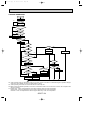
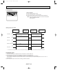
MICROPROCESSOR CONTROL
1.OUTLINE OF MICROPROCESSOR CONTROL
Remote controller board
INPUT to remote controller
● OFF-ON switching.
● COOL/DRY-AUTO-HEAT selector switching.
● Thermostat setting.
● TIMER mode selector-switching and Timer
setting.
● HIGH-LOW fan speed switching.
● AUTO Vane selector (AIR DISCHARGE)
switching.
● Swing louver switching.(AIR SWEEP)
● TEST RUN switching.
● CHECK mode switching.
(Self diagnostic trouble shooting)
Remote controller
● LCD indicator
TIMER OFF TIMER CLOCK AUTO AUTO
CHECK SET TEMP.
FAN
START STOP SPEED
FILTER
AUTO
RETURN
CHECK MODE
TEST RUN
Non-polar, two-wire cable
maximum length 550 yards
12VDC
Indoor
unit
● Processes and transmits
orders.
OUTPUT to remote controller
Signal
Indoor controller board
INPUT from indoor unit
● Room temperature thermistor (RT1)
● Pipe temperature thermistor (RT2)
OUTPUT to indoor unit
● Receives orders from remote controller and temperature data from indoor unit.
● Processes orders and data.
● Controls indoor and outdoor operation.
● Self diagnostic function.
w System control operation.
w Emergency operation.
w Set by dip switch on indoor controller board.
● Transmits the power to remote controller.
Polar three-wire cable
Outdoor unit
● Compressor protection
device working
● Defrosting
START-STOP
● Fan speed control.
● Crankcase heater control
ON-OFF.
● Self diagnostic function
12VDC
Independent Control of
Outdoor Unit
1
2
3
OC277-27
OUTPUT to outdoor unit
1 2 3
● Auto vane’s angle setting.
● Swing louver control ON-OFF.
● Booster heater ON-OFF Control.
● Emergency stop.
● Compressor and
outdoor fan : ONOFF
● Operation mode
change :COOLHEAT.
OC277--1.qxp
01.12.14 13:02
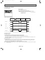
Page 28
2. INDOOR UNIT CONTROL
2-1 COOL operation
<How to operate>
1 Press POWER ON/OFF button.
2 Press the MODE button to display COOL.
3 Press the SET TEMP. button to set the desired temperature.
NOTE: Set temperature changes 2°F when the SET TEMP. button
is pressed one time.
Cooling 65 to 87°F.
SWING
TIMER OFF TIMER CLOCK AUTO AUTO
CHECK SET TEMP.
FAN
START STOP SPEED
FILTER
AUTO
RETURN
CHECK MODE
TEST RUN
<COOL operation time chart>
Operation starts by
POWER button
ON.
Room temperature
becomes equal to
set temperature.
Room temperature
rises above set
temperature.
Operation stops by
POWER button
OFF.
ON
Thermostat
OFF
ON
Indoor fan
OFF
Auto vane
OFF
Booster heater
OFF
LOW or HIGH
LOW or HIGH
ON
ON
OFF
ON
Compressor
OFF
Minimum 3 minutes
w1
w1 Even if the room temperature rise above the set temperature during this period, the compressor will not start until this period has ended.
(1) Compressor control
1 3-minute time delay
To prevent overload, the compressor will not start within 3 minutes after stop.
2 The compressor runs when room temperature is higher than set temperature.
The compressor stops when room temperature is equal to or lower than the set temperature.
The compressor maintains the previous state when the room temperature minus the set temperature is 0 degrees or more,
or lower than 2 degrees.
3 The compressor stops in check mode or during protective functions.
4 Coil frost prevention
To prevent indoor coil frost, the compressor will stop when the indoor coil thermistor (RT2) reads 34°F or below after the
compressor has been continuously operated for at least 16 minutes or more. When the indoor coil temperature rises to
50°F or above, the compressor will start in a 3-minute(w2) time delay.
w2 When the indoor coil temperature is 30°F or less, the compressor starts in 6 minutes.
NOTE : By turning OFF the dip switch SW1-3 on indoor controller board, the start temperature of coil frost prevention changes
from 34°F to 36°F.
OC277-28
OC277--1.qxp
01.12.14 13:02
Page 29
5 Coil frost protection
When indoor coil temperature becomes 5°F or below,coil frost protection will proceed as follows.
<Start condition>
After the compressor has been continuously operated for 3 minutes or more,and the indoor coil temperature has been
5°F or below for 3 minutes,the coil frost protection will start.
<Coil frost protection>
Compressor stops for 6 minutes,and then restarts.
lf the start condition is satisfied again during the first 10 minutes of compressor operation,both the indoor and outdoor
units stop,displaying a check code of “P6” on the remote controller.
<Termination conditions>
Coil frost protection is released when the start condition is not satisfied again during the allowance, or when the COOL
mode stops or changes to another mode.
(2) Indoor fan control
Indoor fan speed LOW/HIGH depends on the remote controller setting.
However, if an outdoor unit abnormality is detected, the indoor fan speed will be LOW, regardless of the remote controller
setting.
When the outdoor unit abnormality detection is released and the fan speed returns to the set speed, the quiet cycle control
will work.
(a) Normal control
( i ) Fan speed LOW/HIGH depends on the remote controller setting regardless of the thermostat ON/OFF.
(ii) Fan speed will remain on LOW if an abnormality in outdoor unit is detected. (5 minutes)
When the abnormality detection is released, the fan speed returns to the set speed.
5 minutes
SET
5 minutes
SET
LOW
LOW
OFF
1 Start-up of outdoor unit abnormality detection.
2 Release of outdoor unit abnormality detection.
3 Unit stop due to outdoor unit abnormality
with P8 indication.
NOTE 1 : Fan stops immediately if the unit stops or the check mode is started.
OC277-29
OC277--1.qxp
01.12.14 13:02
Page 30
(3) Auto vane control
Auto vane position is set to horizontal airflow at the start-up of COOL operation. It can then be changed by the remote controller.
(a) Vane position set mode & swing mode.
( i ) Every time AIR DISCHARGE button is pressed, setting will be changed .
( ii ) Airflow direction can be changed with AIR DISCHARGE button.
1 Fan speed : LOW
Horizontal
40°
60°
SWING
40°
60°
SWING
2 Fan speed : HIGH
Horizontal
20°
<AUTO RETURN>
1 Fan speed : LOW
40
holizontal
AUTO RETURN
60
AUTO RETURN
2 Fan speed : HIGH
holizontal
20
40
60
When 40° degrees or 60° degrees airflow is selected with the LOW fan speed in COOL operation, “AUTO RETURN” will
appear below the temperature display. One hour later, the airflow direction returns to horizontal automatically and “AUTO
RETURN” will disappear. If the airflow direction is set to horizontal during “AUTO RETURN” indication, the time counting
for AUTO RETURN is cancelled.
OC277-30
OC277--2.qxp 1.12.14 1:42 PM Page 31
(4) Detecting abnormalities in the outdoor unit
After the compressor has been continuously operated for 3 minutes, if the difference between the indoor coil temperature
and room temperature is out of RANGE C for 1 minute, the indoor fan speed will turn to LOW. Five minutes later, if the difference is still out of RANGE C,the outdoor unit is functioning abnormally. Thus, the compressor stops and check code
“P8” appears on remote controller.
RANGE A : Indoor coil temperature is more than 9 degrees above room temperature.
RANGE B : Indoor coil temperature is within 9 degrees either way of room temperature.
RANGE C : Indoor coil temperature is more than 9 degrees below room temperature.
Indoor coil temperature
minus room temperature
(degree)
+9
0
-9
RANGE A
RANGE B
RANGE C
OC277-31
OC277--2.qxp 1.12.14 1:42 PM Page 32
2-2 DRY operation
<How to operate>
1 Press POWER ON/OFF button.
2 Press the MODE button to display “DRY”
3 Press the SET TEMP. button to set the desired temperature.
NOTE: The set temperature changes 2°F when the SET TEMP.
button is pressed one time.
Dry 65 to 87°F
SWING
TIMER OFF TIMER CLOCK AUTO AUTO
CHECK SET TEMP.
FAN
START STOP SPEED
FILTER
AUTO
RETURN
CHECK MODE
TEST RUN
<DRY operation time chart>
Operation starts by
POWER button
ON.
Room temperature
becomes equal to
set temperature.
Room temperature
rises above set
temperature.
Operation stops by
POWER button
OFF.
ON
Thermostat
OFF
DRY MODE
DRY MODE
ON
Indoor fan
OFF
ON
Auto vane
OFF
ON
Booster heater OFF
OFF
ON
Compressor
OFF
Minimum 3 minutes w1
w1 Even if the room temperature rises above the set temperature during this period, the compressor will not start until this period has ended.
(1) Compressor control
1 3-minute time delay
To prevent overload, the compressor will not start within 3 minutes after stop.
2 The compressor runs when room temperature is higher than set temperature.
The compressor stops when room temperature is equal to or lower than the set temperature.
The compressor maintains the previous state when the room temperature minus the set temperature is 0°F or more, or
lower than 2°F.
3 The compressor stops in check mode or during protective functions.
OC277-32
OC277--2.qxp 1.12.14 1:42 PM Page 33
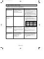
4The compressor will not start when the room temperature is 64°F or below.
The compressor starts intermittent operation when the power is turned ON with room temperature above 64°F. The compressor ON/OFF time depends on the thermostat ON/OFF and the following room temperatures.After 3-minute compressor operation,
● If the room temperature thermistor reads above 85°F with thermostat ON, the compressor will operate for 6 more minutes and then stop for 3 minutes.
● If the room temperature thermistor reads 79°F to 82°F with thermostat ON, the compressor will operate for 4 more
minutes and then stop for 3 minutes.
● If the room temperature thermistor reads 75°F to 79°F with thermostat ON, the compressor will operate for 2 more
minutes and then stop for 3 minutes.
● If the room temperature thermistor reads below 75°F with thermostat ON, the compressor will stop for 3 minutes.
● If the thermostat is OFF regardless of room temperature, the compressor will stop for 10 minutes.
5Coil frost protection
Coil frost protection in DRY operation is the same as in COOL operation.
6Coil frost prevention
Coil frost prevention does not operate in DRY operation.
(2) Indoor fan control
The indoor fan runs on LOW speed during compressor operation. The fan speed cannot be changed with the remote controller. Also, the indoor fan does not run during compressor OFF.
(3) Auto vane control
Same as in COOL operation
(4) Detecting abnormalities in the outdoor unit
An abnormality in the outdoor unit can not be detected in DRY operation.
OC277-33
OC277--2.qxp 1.12.14 1:42 PM Page 34
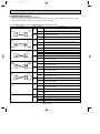
2-3 HEAT operation
<How to operate>
1 Press POWER ON/OFF button.
2 Press the MODE button to display “HEAT”
3 Press the SET TEMP. button to set the desired temperature.
NOTE: The set temperature changes 2°F when the SET TEMP.
button is pressed one time.
Heating 63 to 83°F.
<Display in HEAT operation>
SWING
TIMER OFF TIMER CLOCK AUTO AUTO
CHECK SET TEMP.
FAN
START STOP SPEED
FILTER
AUTO
RETURN
CHECK MODE
TEST RUN
[DEFROST]
The [DEFROST] symbol is only displayed during the defrost operation.
[STANDBY]
The [STANDBY] symbol is only displayed from the time the heating
operation starts until the heated air begins to blow.
<HEAT operation time chart>
Operation starts by
POWER button
ON.
Room temperature
falls below set temperature.
Room temperature
becomes equal to
set temperature.
Operation stops by
POWER button
OFF.
ON
Thermostat
OFF
Extra LOW
ON
Indoor fan
LOW
Extra LOW w1
LOW or HIGH
LOW or HIGH
OFF
ON
Auto vane
1
Horizontal
Depends on remote
controller setting
Horizontal
Depends on remote
controller setting
OFF
ON
Booster heater
w1 Changeable Extra LOW or LOW
by indoor dipswitch SW1- 5 and
SW1- 6 .
OFF
Hot adjustment
Hot adjustment
OFF during thermostat OFF
hot adjustment
defrosting
ON
Compressor
OFF
Minimum 3 minutes w2
ON
Power ON lamp
OFF
ON
STAND BY lamp
From POWER ON until
warm air begins to blow
OFF
w2 Even if the room temperature falls below the set temperature during this period, the compressor will not start until this period has ended.
OC277-34
OC277--2.qxp 1.12.14 1:42 PM Page 35
(1) Compressor control
13-minute time delay
To prevent overload, the compressor will not start within 3 minutes after stop.
2The compressor runs when the room temperature is lower than the set temperature.
The compressor stops when the room temperature is equal to or higher than the set temperature.
3The compressor stops in check mode or during protective functions.
4Overheat protection
<Start condition>
When the indoor coil thermistor reads 158°F or above, the overheat protection will start.
<Overheat protection>
The compressor stops for 6 minutes, and then restarts.
If the start condition is satisfied again within 10 minutes of compressor operation, both the indoor and outdoor units stop,
displaying a check code of “P6” on the remote controller.
<Termination conditions>
Overheat protection is terminated when the start condition is not satisfied again during the allowance (10-minute compressor operation), when operation mode changes to other mode, or when thermostat turns OFF.
(2) Indoor fan control
(a) Normal control
( i )The indoor fan runs on EXTRA-LOW speed during the thermostat OFF.
EXTRA-LOW speed can be changed to LOW or HIGH speed by setting the dip switch SW1-5 and SW1-6.
If the indoor coil temperature becomes more than 5 degrees below the room temperature during the thermostat
OFF, the indoor fan will stop. After, when the indoor coil temperature becomes within 5 degrees of room temperature, the indoor fan will run on EXTRA-LOW speed.
( ii )Hot adjustment
Hot adjustment is a warm-up for HEAT operation
<Start conditions>
The hot adjustment works under any of the following conditions.
● HEAT operation starts.
● Defrosting ends.
● Thermostat turns ON.
[Hot adjustment]
Initially, the indoor fan runs on EXTRA-LOW speed. When 5 minutes have passed or the indoor coil temperature
exceeds 95°F, the fan speed changes to LOW. 2 minutes later, the hot adjustment ends. Then, the fan speed
depends on the remote controller setting.
(iii)The indoor fan stops when the indoor coil temperature is within 9 degrees either way of room temperature.
(iv)To eliminate the remaining heat, the indoor fan runs for the first 1 minute after the booster heater is turned OFF.
(3) Auto vane control
Auto vane position is set to 70 degrees airflow at the start-up of HEAT operation.
(a) Vane position set mode & swing mode.
( i ) Every time AIR DISCHARGE button is pressed, setting will be changed .
( ii ) Airflow direction can be changed with AIR DISCHARGE button.
horizontal
20°
40°
60°
SWING
NOTE : In the following cases, the discharge direction is horizontal regardless of the remote controller setting.
1 During the hot adjustment with fan speed at EXTRA-LOW
2 During defrosting with indoor fan OFF
3 During thermostat OFF
(4) Booster heater control
When the room temperature is 6 degrees below the set temperature, the booster heater will turn ON.
When the room temperature is equal to the set temperature, booster heater will turn OFF.
During the hot adjustment, the booster heater will not work.
<Overheat prevention>
When the indoor coil thermistor rises to 140°F or above, the booster heater cannot work.
When the indoor coil thermistor falls to 131°F or below, the booster heater can work.
OC277-35
OC277--2.qxp 1.12.14 1:42 PM Page 36
(5) Detecting abnormalities in the outdoor unit
When the outdoor unit is determined to be abnormal by the following causes, the compressor will stop and the check code
“ P8 ” will appear on the remote controller display.
( i ) During compressor ON while hot adjustment is set.
1 If the difference between the indoor coil temperature and room temperature is in the RANGE B, the indoor fan will
stop.
2 Within 20 minutes after entering RANGE B (except for the first 10 seconds),
a) If the temperature difference enters RANGE A, the hot adjustment starts,
b) If the temperature difference is still in RANGE B, the outdoor unit is deemed abnormal.
c) If the temperature difference enters RANGE C, defrosting starts.
3 Within 20 minutes after entering RANGE C, if the temperature difference does not return to RANGE B,the outdoor
unit is deemed abnormal.
4 If the temperature difference returns to RANGE B, the next 20 minutes is an allowance period. If the difference enter
RANGE A during the allowance, defrosting ends and the hot adjustment starts. If the difference does not enter
RANGE A during the allowance, the outdoor unit is deemed abnormal.
( ii ) During compressor ON in defrosting
After 30 minutes of defrosting in hot adjustment, if the temperature difference is still in RANGE C, the outdoor unit is
determined to be abnormal.
When RANGE B does not change to RANGE A after 20 minutes have passed since RANGE C had outdoor unit is
determined to be abnormal.
( iii ) During compressor OFF
Not detecting abnormalities.
(6) Indoor coil temperature abnormality detection
An abnormality can be detected during compressor ON, except for the following.
●For the first 30 minutes after the temperature difference between the indoor coil temperature and room temperature
enters the RANGE C.
●When the temperature difference enters the RANGE C until it moves to the RANGE B.
(7) Defrosting operation
After the outdoor unit starts the defrosting operation, when the temperature difference between the indoor coil temperature
and room temperature gets out of RANGE A and into RANGE B, the indoor unit starts the defrosting mode. After the outdoor unit stops the defrosting operation, when the temperature difference returns to the RANGE A, the indoor unit stops
the defrosting mode. While the indoor unit is in the defrosting mode, the indoor fan and the booster heater stop.
w1 RANGE A : Indoor coil temperature is more than 9 degrees above room temperature.
RANGE B : Indoor coil temperature is within 9 degrees either way of room temperature.
RANGE C : Indoor coil temperature is more than 9 degrees below room temperature
Indoor coil temperature
minus room temperature
(degree)
+9
0
-9
RANGE A
RANGE B
RANGE C
OC277-36
OC277--2.qxp 1.12.14 1:42 PM Page 37
2-4 AUTO operation (Automatic COOL/HEAT change over operation)
<How to operate>
1 Press POWER ON/OFF button.
2 Press the MODE button to display “AUTO”
3 Press the SET TEMP. button to set the desired temperature.
NOTE: The set temperature changes 2°F when the SET TEMP.
button is pressed one time.
Automatic 65 to 83°F.
●“AUTOMATIC” works to change by itself the operation
mode either to cooling or heating according to the room
temperature.
SWING
TIMER OFF TIMER CLOCK AUTO AUTO
CHECK SET TEMP.
FAN
START STOP SPEED
FILTER
AUTO
RETURN
CHECK MODE
TEST RUN
(1) Initial mode
1 When AUTO operation starts after unit OFF.
● If the room temperature is higher than the set temperature, operation starts in COOL mode.
● If the room temperature is equal to or lower than the set temperature, operation starts HEAT mode.
2 When AUTO operation starts after COOL or HEAT operation, the previous mode continues.
(2 ) Mode change
1 HEAT mode changes to COOL mode when 15 minutes have passed since the room temperature became 4 degrees
above the set temperature.
2 COOL mode changes to HEAT mode when 15 minutes have passed since the room temperature became 4 degrees
below the set temperature.
To:Set temperature (65~83°F)
(degree)
When room temperature becomes 4 degrees above the set temperature,the operation mode can not be changed
for 15 minutes.
Mode change (HEAT
COOL)
To + 4
To + 2
To
To - 2
To - 4
15 minutes
COOL mode
HEAT mode
Compressor
Mode change
(COOL HEAT)
15 minutes
Start
HEAT mode
ON
OFF
Minimum 3 minutes
(3) Temperature range
AUTO operation is available under the outside air temperatures as follows.
10
0
0°F
20
30
40
50
70
80
COOLING
*
17°F
*
60
HEATING
In case of the wind baffle installed.
OC277-37
90
100
110
120 (°F)
115°F
75°F
OC277--2.qxp 1.12.14 1:42 PM Page 38
2-5 Auto vane control
<How to operate>
To change the air flow direction, press AIR DISCHARGE button.
SWING
TIMER OFF TIMER CLOCK AUTO AUTO
CHECK SET TEMP.
FAN
START STOP SPEED
FILTER
AUTO
RETURN
CHECK MODE
TEST RUN
1
2
3
4
5
Horizontal
20°
40°
60°
SWING
1 Horizontal
2 20° downward
3 40° downward
Available in COOL operation with fan speed on HIGH or
in HEAT operation.
Unavailable in DRY operation.
If fan speed changes from HIGH to LOW during 20°
downward airflow in COOL mode, the direction automatically changes to horizontal.
4 60° downward
5 swing
Changes by pressing
the AIR DISCHARGE
button.
(1) COOL/DRY operation
At the start-up of COOL or DRY operation, the airflow direction in automatically set to horizontal. After, it can be changed
to another direction with AIR DISCHARGE button on the remote controller.
<Auto return>
When 40° or 60° airflow is set with fan speed in LOW, “AUTO RETURN” appears right side of the air direction. One hour
later the direction changes to horizontal degrees, automatically and “AUTO RETURN” disappears.
(2) HEAT operation
At the start-up of HEAT operation, airflow direction depends on the setting of the last operation.
After, it can be changed to another direction with AIR DISCHARGE button. The airflow direction shifts to horizontal regardless of the remote controller settings under any of the following conditions.
● Thermostat OFF
● Defrosting
● Indoor fan speed EXTRA-LOW in hot adjustment
OC277-38
OC277--2.qxp 1.12.14 1:42 PM Page 39
2-6 TIMER operation
WIRED REMOTE CONTROLLER
SWING
TIMER OFF TIMER CLOCK AUTO AUTO
CHECK SET TEMP.
FAN
START STOP SPEED
FILTER
AUTO
RETURN
CHECK MODE
TEST RUN
<Timer function>
AUTO STOP ·········The air conditioner stops after the set time lapses.
AUTO START ········The air conditioner starts after the set time lapses.
AUTO OFF ············Timer is not active.
<How to operate>
1. Press POWER ON/OFF button.
2. Press “TIMER ON/OFF” button to select AUTO STOP or AUTO
START.
3. Press “CLOCK/TIMER” button to set desired time.
Time setting is in 1 hour units for up to 24 hours.
Each time TIMER SET button is pressed, set time increases by 1
hour. When TIMER SET button is pressed and held, the set time
increases by 1 hour every 0.5 seconds.
4. To cancel the timer operation, press POWER ON/OFF button.
<Timer setting example>
AUTO
STOP
This setting will stop the operation in 8hours.
With the lapse of time, time display changes in 1hour units,
showing remaining time.
2-7 Test run
<Before test run>
● After installing, wiring, and piping the indoor and outdoor units, check for refrigerant leakage, looseness in power supply or
control wiring, and mistaken polarity.
● Use a 500-volt measure to check the resistance between the power supply terminal block and ground to make sure that it is
at least 1.0MΩ.
Attention:
Do not use the air conditioner if resistance is less than 1.0MΩ.
SWING
F
COOL
FAN
SPEED
MODE
AUTO
RETURN
TIMER ON/OFF CLOCK/TIMER FAN SPEED AIR DISCHARGE FILTER
AIR SWEEP
SET TEMP.
TIMER SET
CHECK
TEST RUN
REMOTE CONTROLLER
PAR-JH240KUS
<How to operate>
1. Turn ON main breaker.
2. Press TEST RUN button twice. “TEST RUN” is displayed on
remote controller.
3. Select “COOL” with MODE button to check that cool air is
beginning discharged.
Select “HEAT” with MODE button to check that warm air is
beginning discharged.(after a while)
4. Select LOW/HIGH with FAN SPEED button to check that the fan
speed changes properly.
5. Press AIR DISCHARGE button to check auto vane operation.
6. Check outdoor fan operation.
7. Check compressor operation referring to the indoor coil
temperature code displayed on the remote controller.
8. After checking, press the ON/OFF button.
TEST RUN button
Displayed during test run
·The test run works for 2 hours and stops automatically.
To cancel the test run, press ON / OFF button or TIMER ON / OFF button.
OC277-39
OC277--2.qxp 1.12.14 1:42 PM Page 40
(1) Indoor coil temperature code
During the test run, the indoor coil temperature code from 1 to 15 is displayed on the remote controller instead of room
temperature. The code should fall with the lapse of time in normal COOL operation, and should rise in normal HEAT
operation.
Code
1
Indoor coil temperature ~34(36)°F
2
3
4
5
6
7
8
36(37)°F~50°F
~59°F
~68°F
~77°F
~86°F
~95°F
~104°F
Code
9
10
11
12
13
14
15
Indoor coil temperature
~113°F
~122°F
~131°F
~140°F
~158°F
~191°F
Thermistor abnormality
(2) Trouble during test run
● If the unit malfunctions during the test run, refer to section 10 in this manual entitled “TROUBLESHOOTING.”
● When the optional program timer is connected to the conditioner, refer to its operating instructions.
2-8 Emergency operation
When the remote controller or microprocessor malfunctions but all other parts are normal, emergency operation is started
by setting the dip switch SW3 on the indoor controller board.
<Before emergency operation>
1. Make sure the compressor and the indoor fan are operating normally.
2. Locate the defect with the self-diagnostic function. When the self-diagnostic function indicates “protective function is
working”, release the protective function before starting the emergency operation.
CAUTION: When the self-diagnostic function indicates a check code of “P5” (drain pump malfunction), do not start the
emergency operation because the drain may overflow.
<How to operate>
1. For emergency cooling, set the dip switch SW3-1 to ON and SW3-2 to OFF.
For emergency heating, set the dip switch SW3-1,2 to ON.
Emergency
cooling
1
1 ON
2
Emergency
heating
1
2
1.2 ON
Normal
operation
1
2
SW3
1.2 OFF
Indoor controller board
2. Turn ON the outdoor unit breaker and then ON the indoor unit breaker.
Emergency operation will now start.
3. During emergency operation, the indoor fan operates on high speed, the auto vanes do not operate.
4. To stop emergency operation, turn OFF the indoor unit breaker.
5. Movements of the vanes do not work in emergency operation, therefore you have to slowly set them manually to the
appropriate position.
NOTE: The remote controller POWER ON/OFF button can not start/stop emergency operations.
CAUTION: Do not use emergency cooling for more than 10 hours, as the indoor coil may freeze.
OC277-40
OC277--2.qxp 1.12.14 1:42 PM Page 41
2-9 Dip switch functions
Each figure shows the initial factory setting.
(1). On remote controller board
1. SW17(Address selector)
1 2 3 4 5 6 7 8
ON
OFF
SW17-1~6) For address setting
SW17-7) When two remote controllers are used,this switch sets the controller function.
OFF:The remote controller is set as a main controller.
ON:The remote controller is set as a sub controller.
SW17-8) Switch for system back-up.
OFF:Without back-up
ON:With back-up
2. SW18(Function selector)
1 2 3 4 5 6 7 8
ON
OFF
SW18-1) Switch for timer
OFF:Single day ON:timer every day
SW18-2) Switch for filter sign
OFF:filter sign absent
ON:filter sign present
SW18-3) Switch for filter sign time setting.
OFF:100Hr ON:2500Hr
SW18-4~8) Not for use.
(2). On indoor controller board
1. SW1 (Mode selector)
1 2 3 4 5 6 7 8 9 10
ON
OFF
SW1-1) Switch that changes between FAN mode and AUTO mode
OFF:AUTO mode for models with heat pump
ON:Fan mode for models without heat pump
SW1-2) Switch for drain pump
OFF:The drain pump works in COOL and DRY operation.
ON:The drain pump works in both COOL and DRY and HEAT operation.
SW1-3) Switch to change the temperature to start coil frost prevention
OFF:34°F
ON:36°F
SW1-4) Switch for set temperature adjustment in HEAT mode
During HEAT operation,warm air collects near the ceiling.When the indoor unit is installed near the ceiling,the
temperature read by room temperature thermistor differs from the actual living-space temperature by about 7
degrees. Therefore,the room temperature read by room temperature thermistor must be lowered by 7 degrees.
OFF:7-degree adjustment
ON:NO adjustment
SW1-5) Switch for fan speed during thermostat OFF in HEAT operation
OFF:EXTRA LOW
ON:LOW
SW1-6) Switch for fan speed during thermostat OFF in HEAT operation
OFF:EXTRA LOW or LOW(set with SW1-5)
ON:LOW or HIGH(set with remote controller)
SW1-7) Switch for detecting abnormalities in the outdoor unit abnormality detection
OFF:When an abnormality occurs,it is detected.
ON:Even if an abnormality occurs,it can not be detected.
SW1-8) Switch for auto restart function
OFF:This function does not work
ON:This function works.
SW1-9, 10) Not for use.
OC277-41
OC277--2.qxp 1.12.14 1:42 PM Page 42
2. SW2 (Address selector)
1 2 3 4 5 6
Used in setting the unit-address for group control.
For further information,refer to page OC277-51.
ON
OFF
3. SW3 (Emergency operation switch)
Normal operation
For emergency cooling
1 2
ON
OFF
For emergency heating
1 2
1 2
ON
OFF
ON
OFF
4. SW5 (Model selector)
1 2 3 4
ON
OFF
SW5-1) Not for use.
SW5-2) OFF:For models with heat pump
ON: For models with cooling only
SW5-3) Not for use.
SW5-4) Not for use.
5. SW6 (Address selector)
1 2 3 4
ON
OFF
This switch is not available for series PCH.
6. SW7 (Model selector)
Switch to set the output of phase-controlled indoor fan motor.
Address setting is available at any time.
The initial factory setting by is based on each capacity.
Service Ref.
SW7
PCH24GK
ON
OFF
PCH30GK
PCH36GK
ON
OFF
ON
OFF
1 2 3
1 2 3
PCH42GK
ON
OFF
1 2 3
1 2 3
7. SW8 (Option)
1 2 3 4 5 6
ON
OFF
SW8-1~2) Not for use.
SW8-3~4) Not for use.
SW8-5) Not for use.
SW8-6) OFF:For 230V power supply
ON: For 208V power supply
8. SW9 (Model selector)
1 2 3 4 5
ON
OFF
SW9-1~5) Keep this switch.
2-10. INDOOR FAN CONTROL
Fan motor max. rotational frequency
Service Ref.
PCH24GK
PCH30GK
PCH36, 42GK
Voltage
[V]
208/230
208/230
208/230
OC277-42
100% rotational frequency(rpm)
60Hz
1180/1290
1190/1260
1220/1310
OC277--2.qxp 1.12.14 1:42 PM Page 43
10
TROUBLE SHOOTING
1. REMOTE CONTROLLER DISPLAY ABNORMALITY
Display abnormality
Cause
Check points
The display “centrally controlled” on remote controller does not disappear.
1) Wrong address setting of remote controller/indoor controller board.
2) Timer adapter is connected to the
remote controller.
3) Signal transmission error between
indoor unit and remote controller.
1) Check the address setting of remote controller
and indoor controller.
2) Check if the timer adapter is used correctly.
3) 1 Turn another remote controller’s DIP SW177 ON to make it sub controller.
2 Connect the sub controller to the unit, and
turn circuit breaker ON.
● If the display “centrally controlled” disappears, replace the original remote controller.
● If the display remains the same, replace the
indoor controller board.
When remote controller
POWER switch is turned
to ON, the check code
“E0”appears.
1) Signal transmission error between
indoor unit and remote controller
1) 1 Connect a sub remote controller.
2 Turn circuit breaker ON.
If the display “centrally controlled” remains,
replace the indoor controller board.
3 If the display disappears, turn the remote
controller POWER switch ON and check as
follows.
Remote controller Sub remote controller
Malfunction
Malfunction of
1 Operating Display E0 Display
Indoor Unit
of
2 Operating Display Operating Display Malfunction
Remote controller
Malfunction of
Indoor Unit and
Remote Controller
3 No Display
E0 Display
4 No Display
of
Operating Display Malfunction
Remote controller
When remote controller
POWER switch is turned
to ON, operating display
appears, but disappears
soon.
1) Short circuit of indoor/outdoor connecting wire
2) Short circuit of transmission wire.
3) Short circuit of drain sensor heater circuit.
4) Wrong operation of remote controller
due to noise wave emitted by other
appliances.
1), 2) Check the wire
3) Measure the resistance of the drain sensor
connector CN50 1 - 3. If normal, the value
should be 82Ω.
4) Turn the circuit breaker OFF, and then turn
ON.
If the remote controller remains abnormal,
despite the above measures, replace the indoor
controller board.
Despite turning POWER
switch ON, the remote
controller display does not
appear.
1) Damaged remote controller.
2) Short circuit of transmission wire.
3) Bad contact of indoor CN40.
4) CN40 is attached to a sub unit.
5) Damaged transformer.
6) Bad contact of CN2D.
7) Broken fuse.
8) Circuit breaker OFF.
1) Measure the voltage between terminals of
remote controller. If no voltage, remove the
terminals and measure the voltage between
wires. If the voltage is between 6VDC and
12V, replace the remote controller.
2) ~ 8) Check each point.
If normal, replace the indoor controller
board.
OC277-43
OC277--2.qxp 1.12.14 1:42 PM Page 44
2. SELF DIAGNOSTIC FUNCTION WITH REMOTE CONTROLLER
(WIRED REMOTE CONTROLLER)
2-1 When malfunction occurs during operation
When a malfunction occurs, the indoor and outdoor units stop and the malfunction is displayed on the LCD of the remote
controller.
(1) ON the set temperature display part, “CHECK” appears, and the unit CHECK mode
address and the check code are displayed alternately at one-second
intervals.
Example
Check
code
Unit
address
MODE
TIMER ON/OFF CLOCK/TIMER FAN SPEED AIR DISCHARGE FILTER
AIR SWEEP CHECK
(2) When one remote controller controls several units in the group control, the LCD shows the unit address and check code of the first malfunctioning unit.
(3) To cancel the check mode, press the ON/OFF button. In remote
ON/OFF control, press the remote ON/OFF switch. In centralise
control, turn OFF the ON/OFF button of centralise controller.
SET TEMP.
TIMER SET
TEST RUN
REMOTE CONTROLLER
Check button
NOTE: The latest check code is memorise, even if the check mode is cancelled by the way mentioned above. It takes 60
seconds maximum to display the memorise check code.
2-2 How to use the self diagnostic function for service
A. For normal control with one unit and one remote controller
(1) Pressing the CHECK button on the remote controller twice starts the self diagnostic function.
(2) During the self diagnostic function, “CHECK MODE” appears at two positions on the remote controller display. Then, at
least 10 seconds later, the unit address and the check code is alternately displayed at one-second intervals.
(3) Check and repair the unit according to the check code. (Refer to the next page.)
B. For group control using one remote controller
(1) Pressing the CHECK button on the remote controller twice starts the self diagnostic function.
(2) Press the
SET TEMP. button or
SET TEMP. button on the remote controller to advance or go back to the
unit address. Each time
SET TEMP. button is pressed, the unit address advances by one. Each time
SET
TEMP. button is pressed, the unit address goes back by one.
The check code and the unit address, appear alternately.
(3) The check code “U8” means no malfunction has occurred since installation.
The check code “E0” means the following conditions:
● The unit address displayed on the remote controller does not apply to any unit.
● power is not supplied to the unit.
● Signal transmitting/receiving circuit is abnormal.
(4) Check and repair the unit according to the check code. (Refer to the next page.)
OC277-44
OC277--2.qxp 1.12.14 1:42 PM Page 45
Check
Diagnosis of malfunction
Cause
Check points
code
E0
Signal transmitting/receiving During individual unit control
1) Check the transmission wire.
error
1) Bad contact of transmission
2) Check with another remote controller. If “E0” is
(Indoor controller does not
wire
still indicated, replace the indoor controller
respond to remote controller 2) Signal transmitting/receiving cirboard.
signal.)
cuit is abnormal.
If other check code appears. replace the original remote controller.
P1
Abnormality of room temper- 1) Bad contact of thermistor
ature thermistor (RT1)
2) Damaged thermistor
P2
Abnormality of indoor coil
thermistor (RT2)
P3
Signal transmission error
(Remote controller does not
respond to indoor controller
signal.)
1) Check the transmission wire.
1) Bad contact of transmission
2) Check with another remote controller.
wire
If “P3” is still indicated, replace the indoor
2) Signal transmitting/receiving cirboard.
cuit is abnormal.
If other check code appears, replace the origi3) Wrong operation due to noise
nal remote controller.
wave emitted by other appli3) Short-circuit between 1 and 2 of CN40 and
ances
attach CN40 to the following units.
● Second unit in twin control
● Second and third units in triple control
● Sub units in group control
P4
Abnormality of drain sensor
1) Bad contact of transmission
wire
2) Damaged thermistor
1) Check the connector.
2) Measure the resistance of the thermistor 1 - 3.
32°F ···6kΩ
59°F ···3.2kΩ 86°F ···1.8kΩ
41°F ···4.8kΩ 68°F ···2.6kΩ 95°F ···1.5kΩ
50°F ···3.9kΩ 77°F ···2.2kΩ 104°F 1.3kΩ
If the resistance is normal, replace the indoor
controller board.
P5
Malfunction of drain pump
1) Malfunction of drain pump
2) Damaged drain sensor
1) Check the drain pump.
2) Check the drain sensor.
(Check the drop of water is on.)
If the resistance is normal, replace the indoor
controller board.
P6
Freezing protection/
overheating protection
is working.
1) Short cycle of air cycle
2) Dirty air filter
3) Damaged fan
4) Abnormal refrigerant
1)
2)
3)
4)
P7
System error
1) Wrong address-setting
1)
2) Signal transmitting/receiving cir- 2)
cuit of remote controller is
abnormal.
3) Wrong SW6-setting
3)
Check the address-setting.
Check with another remote controller. If check
code other than “P7” appears, replace the original remote controller.
Check SW6 setting.
P8
Abnormality in outdoor unit
1) Wrong wiring of indoor/outdoor
connecting wire
2) Reversed phase
3) Protection device is working
4) Damaged outdoor coil thermistor
Check the indoor/outdoor connecting wire.
Change the connection of electric wiring.
Check the protection device.
Measure the resistance of the outdoor coil thermistor. If the resistance is normal, replace the
outdoor controller board.
OC277-45
1) Check the thermistor.
2) Measure the resistance of the thermistor.
Normal resistance should be as follows.
32°F····15kΩ
86°F·····4.3kΩ
50°F······9.6kΩ 104°F ···3.0kΩ
68°F······6.3kΩ
If the resistance is normal, replace the indoor
controller board.
1)
2)
3)
4)
Clear obstructions from the air cycle.
Clean the air filter
Check the fan.
Check the refrigerant temperature.
OC277--2.qxp 1.12.14 1:42 PM Page 46
3. WRONG WIRING ON SITE
3-1 Between remote controller and indoor unit
If the wire is disconnected between the remote controller and the indoor unit, nothing is displayed on the remote controller
when the POWER button is pressed. The beep sound will also not be heard.
3-2 Phenomenon due to wrong wiring between indoor and outdoor units
Wrong wiring
Mode
Thermostat
OFF
Indoor
Outdoor
1
1
2
2
3
3
COOL
ON
OFF
HEAT
Indoor
Outdoor
1
1
2
2
3
3
Outdoor
1
1
2
2
3
3
Outdoor
1
1
2
2
3
3
OFF
Outdoor unit stops.
ON
Operation stops. 9 minutes later, check code “P8” appears on
remote controller display.
OFF
Operation stops.
ON
Operation stops. 27 minutes later, check code “P8” appears on
remote controller display.
OFF
Outdoor unit stops.
ON
Operation stops. 9 minutes later, check code “P8” appears on
remote controller display.
OFF
Operation stops.
ON
Operation stops. 27 minutes later, check code “P8” appears on
remote controller display.
OFF
Outdoor unit stops.
ON
Operation stops. 9 minutes later, check code “P8” appears on
remote controller display.
OFF
Operation stops.
ON
Operation stops, 27 minutes later, check code “P8” appears on
remote controller display.
OFF
Outdoor unit stops.
ON
Operation stops. 9 minutes later, check code “P8” appears on
remote controller display.
OFF
Operation stops.
ON
Operation stops. 27 minutes later, check code “P8” appears on
remote controller display.
OFF
Operation stops.
ON
Operation stops. 9 minutes later, check code “P8” appears on
remote controller display.
OFF
Operation stops. 4-way valve turns OFF.
ON
27 minutes later, check code “P8” appears on remote controller
display.
COOL
COOL
COOL
HEAT
Indoor
Outdoor
1
1
2
2
3
3
COOL
HEAT
Disconnection between 1 and 1 or 2
and 2.
COOL
HEAT
Disconnection between 3 and 3.
COOL
4-Way valve turns ON. 9 minutes later, check code “P8” appears
on remote controller display.
Cooling operation. Several minutes later, check code “P8” appears
on remote controller display.
Normal operation until first thermostat OFF.
HEAT
Indoor
Operation stops.
ON
HEAT
Indoor
Phenomenon
–
Normal operation.
OFF
Operation stops. 4-way valve turns OFF.
ON
Operation stops. 27 minutes later, check code “P8” appears on
remote controller display.
HEAT
OC277-46
OC277--2.qxp 1.12.14 1:42 PM Page 47
4. OTHER TROUBLES AND CAUSES
Vanes do not work.
Unit stops after 5 to
20 seconds operation
Air discharge display
is OFF and AIR DISCHARGE button does
not operate.
In this case, remote
controller is normal.
Power ON/OFF button
is not available.
Vane motor does not work.
Connector is poorly connected.
Vane motor is poorly assembled.
Indoor controller board is damaged.
Vane motor is damaged.
Vane motor relay is damaged.
Protection function is working.
Refer to check code on remote controller display.
See page OC277-45.
Indoor controller board
deems the auto vanes
are not attached to the
unit.
Horizontal angle can
not be detected.
Beep sound is heard,
but display is turned
OFF.
Beep sound is not heard,
and display remains OFF.
Indoor controller is
damaged.
Dip switch setting is
wrong.
Indoor controller is
damaged.
Vane motor is damaged.
Auto vane is wired after
power is turned to ON.
Vane motor is damaged.
Indoor/outdoor connecting wire is connected
incorrectly.
Indoor/outdoor connecting wire shorts.
Compressor protector
is damaged.
Outdoor controller
board is defective.
Remote controller is
damaged.
Transmission wire is
poorly connected
“CENTRALLY CONTROLLED” is displayed.
OC277-47
Transmission wire is
damaged.
Connector is poorly
connected.
Indoor terminal block is
poorly connected.
Remote controller terminal block is poorly
connected.
OC277--2.qxp 1.12.14 1:42 PM Page 48
5. How to check the parts
Parts name
Check points
Room temperature
thermistor
(RT1)
Liquid pipe
thermistor
(RT2)
Vane motor (MV)
Pink
Disconnect the connector then measure the resistance using a tester.
(Ambient temperature 50°F to 86°F)
Normal
Abnormal
4.3k" to 9.6k"
Open or short
(Refer to the next page for a detail.)
Measure the resistance between the terminals using a tester.
(Ambient temperature 77°F)
4
Normal
M
24,30,36,42GK
Connector
Orange 2
Red 5
Abnormal
Red — Yellow
1
3
Blue
Yellow
Red — Blue
150"
Red — Orange
Open or short
Red — Pink
Fan motor (MF)
Measure the resistance between the terminals using a tester.
Relay connector
1
Red
2 White
3 Black
Protector
1
2
3
Normal
Motor terminal
or
Relay connector
24GK
30,36,42GK
Red-Black
41.1"
20.4"
White-Black
54.3"
20.7"
Abnormal
PCH
Opening and closing temperature of protector.
Open: 266i41°F (Fan motor OFF)
Close: 176i68°F (Fan motor ON)
OC277-48
Open or short
OC277--2.qxp 1.12.14 1:42 PM Page 49
<Thermistor Characteristic graph>
Thermistor for
lower temperature
< Thermistor for lower temperature >
Room temperature thermistor(RT1)
Liquid pipe thermistor(RT2)
50
Thermistor R0=15k' ± 3%
Fixed number of B=3480k' ± 2%
Rt=15exp { 3480(
32°F
50°F
68°F
77°F
86°F
104°F
1
273+{(t-32)/1.8}
1 )}
273
15k'
9.6k'
6.3k'
5.4k'
4.3k'
3.0k'
Resistance (K")
40
30
20
10
0
OC277-49
-4
14
32 50 68 86
Temperature (°F)
104 122
OC277--2.qxp 1.12.14 1:42 PM Page 50
11
SYSTEM CONTROL
1. VARIETY OF SYSTEM CONTROL FUNCTIONS
1 Group control with
a single remote
controller
(See page OC27751.)
Unit
Unit
Many units, installed at different locations, can be started
and controlled with a single remote controller. The remote
controller can be mounted in a different location using a
non-polar two-wire cable, which can be extended up to
500m. A maximum of 50 units can be controlled with a
single remote controller. All units operate in the same
mode.
Unit
Remote
controller
2 Control using two
remote controllers
(See page OC27752.)
Unit
Unit
Two remote controllers can be used to control either one
unit or a group of units. Units can then be controlled from
a distance or at close range. Units operate according to
the latest command from either remote controller.
Unit
Remote
controller
3 Both remote
ON/OFF and individual controls
(See page OC27752.)
w Timer adapter
(PAC-SA89TA-E)
is needed.
Optional
adapter
Relay box
Unit
Remote
ON/OFF
switch
4 Individual control
by grouping
remote controllers
(See page OC27753.)
Remote
controller
Unit
Unit
By grouping the remote controllers in one place, several
units installed at different locations can be controlled individually, and operation conditions of all units are visible
without a special control board. The control method is the
same as that of the single unit with a single remote controller.
Unit
Remote
controller
5 Multiple remote
control display
(See page OC27754.)
w Multiple display
adapter
(PAC-SA88HA-E)
is needed.
6 Auto restart function
(See page OC27754.)
Unit
Remote control
display board
Unit
All units can be turned on or off simultaneously using a
remote ON-OFF switch. Also, each unit can be controlled
individually by each remote controller. Dunning remote
ON-OFF control, a message of “CENTRALLY CONTROLLED” is displayed on the LCD of the remote controller.
This is available for both one unit control and several units
control.
Unit
Several units can be controlled with a remote control display board. Operation conditions of all the units are visible with the remote control display board.
Individual control by each remote controller is also possible.
Remote
controller
Circuit breaker
Remote
controller
A unit can be started or stopped with the circuit breaker
on or off.
Remote controller is also available.
With this function, when the power is restored after power
failure, the unit will restart automatically. (However, when
the remote controller POWER ON/OFF button is OFF, the
unit will not start.)
OC277-50
OC277--2.qxp 1.12.14 1:42 PM Page 51
2. GROUP CONTROL WITH A SINGLE REMOTE CONTROLLER
A maximum of 50 units can be started in order according to the dip switch settings
Figure 1
To remote
controller
To next
unit
To next unit
1 2 3 L1 L2 GR
Master unit
electrical box
1 2 3 L1 L2 GR
2-1 How to wire
(1) Connect the remote controller to the double terminal block
on the indoor controller board of the master unit (No.0 unit).
(See Figure 1.)
(2) Connect the double terminal block of the master unit to the
double terminal block of No.1 unit.
(3) Connect the double terminal block of No.1 unit to the double terminal block of No.2 unit.
(4) Continue the process until all the units are connected with
two-wire cables. (See Figure 2.)
(5) Remove the connector CN40 from the indoor controller
board of each unit except the master unit. (See Figure 3.)
(6) Set the unit-address of each unit with SW2 on the indoor
controller board following the instructions below.
2-2 How to set unit-address
The unit-address also serves as a successive-start timer which
starts each unit at intervals of 1 second. If two or more units
have the same unit-address in a group control, operation stops
due to system error. Be sure to set SW2 correctly following the
instructions below.
(1) Each lever of SW2 shows the number as follows.
SW2-1 : 1
SW2-4 : 8
SW2-2 : 2
SW2-5 : 16
SW2-3 : 4
SW2-6 : 32
(2) Total number of levers turned to ON shows the address of
the unit.
For example, to set No.3 unit, turn ON SW2-1 and SW2-2.
(3) In this way, set from the master unit to the last unit.
Do not forget to set the master (No. 0) unit.
Next unit
electrical box
The last unit
dose not have
this wire.
Figure 2
Master
unit
No.1 unit
No.2 unit
Last unit
2-wire cable
Figure 3
Indoor controller board
▼
Should be removed
from all units other
than unitNo.0:
(Master Unit).
CN40
CN40
SW2
SW2
ON
1
2
3
4
5
6
Setting examples
Master (No. 0) unit
No. 1 unit
No. 2 unit
No. 4 unit
No. 8 unit
No. 16 unit
No. 32 unit
ALL OFF
1 ON
2 ON
3 ON
4 ON
5 ON
6 ON
SW2
1
Unit address & start
delay in seconds.
2
3
4
5
6
1
0
2
3
4
5
6
1
1
2
3
4
5
6
1
2
2
3
4
5
6
1
4
2
3
4
5
6
1
8
2
3
16
4
5
6
1
2
3
4
32
2-3 Unit control
The remote controller can control all units ON/OFF, temperature, air flow, and swing louver. However, the thermostat in
each unit turns ON or OFF individually to adjust to the room temperature.
OC277-51
5
6
OC277--2.qxp 1.12.14 1:42 PM Page 52
3. CONTROL USING TWO REMOTE CONTROLLERS
Two remote controllers can be used to control either one unit or a group of units. Units operate according to the latest command from either of the two remote controllers.
Before operation, be sure to set one remote controller as the “main controller” and the other as the “sub controller”, using dip
switch SW17-7 of the remote controller.
Figure 4
Individual
Multiple operation
operation
Remote
controller
Remote
controller
Remote
controller
Remote
controller
3-1 How to set SW17-7 (See Figure 5.)
(1) For the main remote controller, turn SW17-7 OFF.
(2) For the sub remote controller, turn SW17-7 ON.
3-2 Remote controller LCD indication
(1) The same indications always appear on both the
main and sub remote controllers, except during the
timer operations.
(2) Timer operations can be set with either of the two
remote controllers. However, LCD indication appears
only on the remote controller used for timer-settings.
(3)If both remote controllers are set for timer operation
with different time-settings, the timer operation with
the shorter remaining-time is effective.
(4) Self-diagnostic function is available with either of the
two remote controllers. If one of the remote controllers is used for the self-diagnostic function, the
other remote controller displays the check mode.
If the self-diagnostic function is reset by either of the
two remote controllers, both remote controllers are
reset.
Figure 5
Remote controller
SW17
Main remote controller
Sub remote controller
F
OF
8
7
6
5
4
3
2
F
OF
1
8
7
6
5
4
3
2
1
Turn SW17-7 ON.
4. REMOTE ON-OFF AND INDIVIDUAL REMOTE CONTROLS
This method is available to control one unit or any number of units.
The following operations are available by connecting a relay, a timer adapter (PAC-SA89TA-E), and a remote ON/OFF switch
to the system. Timer adapter is an optional part. Other parts are available on the market.
(A) To start all units in order by remote ON-OFF switch
(B) To stop all units simultaneously by remote ON-OFF switch
(C) To switch between the remote ON-OFF control and the individual remote control
4-1 System
Figure 6 shows the case of three units. The same is the case with any number of units.
Figure 6
Timer adapter
PAC-SA89TA-E
power supply of
control circuit
Remote
ON/OFF
switch
Relay box
2-wire
remote
Timer adapter cables
controller
cable
Remote
controller
OC277-52
OC277--2.qxp 1.12.14 1:42 PM Page 53
NOTE1 : Install the relay box where you can be serviced it easily.
NOTE2 : For control circuit wiring, use a wire of No. 14 AWG or a control cable according to the power supply of control
circuit.
NOTE3 : When the power supply of the control circuit is 208/230V AC,
● Do not connect the control circuit wire to the remote controller cable directly.
● Do not place the control circuit wire and the remote controller cable into the same conduit tube.
4-2 Basic wiring
Caution : Before starting all units simultaneously by the remote ON-OFF switch, be sure to connect a sequence-start timer
into the remote ON-OFF circuit. Otherwise, a rush of starting current may damage the power supply.
Remote
ON/OFF
switch
Power
supply
No.1 unit
relay box
No.2 unit
relay box
SW1
Next unit
SW2
Glow switch or pilot lamp can be
combined to easily identify the
on-off mode of SW1 and SW2.
To
No.1
unit
T
T
X2
X2
T
To
No.2
unit
X2
T
X2
Remote controller
Timer adapter cables
4-3 Switch function of remote ON-OFF switch
SW1
(Switches between
remote ON and OFF.)
ON
(Start)
OFF
(Stop)
SW2
(Switches between remote ON-OFF and individual control)
ON
OFF
(Remote ON-OFF control)
(Individual control)
All units start together.
w1
Each unit can be controlled by each
Individual control is not available.
remote controller.
All units stop together.
w2
Remote ON-OFF switch is not available.
Individual control is not available.
w1After all units start together, if SW2 is turned OFF, each unit can be individually stopped by each remote controller.
w2After all units stop together, if SW2 is turned OFF, each unit can be individually started by each remote controller.
5. INDIVIDUAL CONTROL BY GROUPING THE
REMOTE CONTROLLERS
● Grouping the remote controllers allows individual control and centralise monitoring of units installed in different places without a special control board.
● Remote control cables are extendible up to 550 yards When the
cable length exceeds 33ft, use the double-insulated two-care cable
such as Belden 9407. Also, the cable thickness must be No. 22
AWG or above.
● When gathering the power ON/OFF switches of air conditioners
near the remote controllers, you should also install the power
ON/OFF switch near each unit to prevent electric trouble during
servicing.
OC277-53
Remote
controller cable (2-core)
Remote controller
OC277--2.qxp 1.12.14 1:42 PM Page 54
6. MULTIPLE REMOTE CONTROL DISPLAY
Indoor controller board
You can control several units with a multiple remote control display, by
wiring an optional multiple display adapter (PAC-SA88HA-E) with relays
and lamps on the market.
How to wire
(1) Connect the multiple display adapter to the connector CN51 on the
indoor controller board.
(2) Wire three of the five wires from the multiple display adapter as shown
in the figure below.
<Wiring >
X2
YELLOW
X1
ORANGE
RED
Electrical insulation is needed.
BROWN
1
connector(5P)
GL
X2
GREEN
5
CN51
CN51
Optional multiple display
adapter
X1
RL
Power
supply
Wiring at the actual place
CN51
The maximum distance between
indoor board and relay is 33ft.
[Notes on Signs]
X1:Relay (for operation lamp)
X2:Relay (for check lamp)
RL:Operation Lamp
GL:Check Lamp
[Field supplied parts]
Relays:12V DC with rated coil power
consumption below 0.9W.
Lamps:Matching to power supply voltage.
<System>
3wires
3wires
3wires
Power
supply
No.1 unit
2wires
No.2 unit
Remote
controller
cable
Multiple remote control
ON-OFF display
(Field supply)
Remote
controller
No.3 unit
Relay box
(Field supply)
Remote
controller
Remote
controller
(Operation check)
<Wiring diagram>
Power
supply
RL-1
X1-1
GL-1
X2-1
RL-2
X1-2
GL-2
X2-2
RL-3
X1-3
GL-3
X2-3
X1-1
X2-1
X1-2
1
Multiple remote
controller adapter
5
No.1 unit
1
No.2 unit
X2-2
X1-3
X2-3
Multiple Remote Control Display
5
1
5
No.3 unit
connect to
the connector CN51
Relay box
7. AUTO RESTART FUNCTION
By setting the dip switch SW1-8 to ON, the air conditioner can be started/stopped by power supply ON/OFF.
If the air conditioner is OFF before the power failure, it will not start operation by power restore.
•This function is mainly to emergency performance when the power supply stops temporarily. Therefore, since the protection function (for example, clank case heater and prevention from restarting in 3 minutes, etc.) of the device is not operated, this function should not be used mostly.
8. TIMER OPERATION OR THE OPERATION BY AN EXTERNAL SIGNAL
<Wiring>
A
A
B
B
Brown
Red
A : an optional timer adapter
B : a single-throw switch
Orange
Remote controller
Brown
Red
Orange
Remote controller
For remote control, connect the optional timer adapter (PAC-SA89TA-E)
OC277-54
OC277--2.qxp 1.12.14 1:42 PM Page 55
12
DISASSEMBLY PROCEDURE
PCH24GK
OPERATING PROCEDURE
1. Removing the air intake grille
(1) Slide the intake grille holding knobs (at two locations)
backward to open the intake grille.
(2) When the intake grille left open, push the stoppers on the
rear hinges (at two locations) to pull out the intake grille.
PHOTOS&ILLUSTRATIONS
Figure 1
Intake grille
slide
Intake grille
Holding knobs
Hinges
Pull out the intake grille
2. Removing the electrical box
(1) Remove the air intake grille.
(2) Remove the screw from the beam and remove the beam.
(3) Remove the screws from the electrical cover, and
remove the electrical cover.
(4) Disconnectors including CN6V and CN21.
(5) Remove the screws from the electrical box and pull out
the electrical box.
<Electrical parts in the electrical box>
Terminal block (for power supply)
Terminal block (for in/outdoor connecting wire)
Terminal block (for remote controller)
Fan motor capacitor
Indoor control board
Relay
Power Board
Figure 2
Beam
Slide to the left
Screws (electrical cover)
Clamp
Electrical cover
Screws (electrical box)
Photo 1
Fan motor
capacitor
Power
board
OC277-55
Relay
Relay
Indoor control
board
Terminal block
(remote control)
Terminal block
Terminal block
(in/out connecting) (power supply)
OC277--2.qxp 1.12.14 1:42 PM Page 56
OPERATING PROCEDURE
PHOTOS&ILLUSTRATIONS
3. Removing the fan motor
(1) Remove the intake grille.
(2) Disconnect the fan motor connector.
(3) Remove the screw for removing the motor support at both
left and right side.
(4) Loosen the set screws at the fan motor side of the connecting joint.
(5) Slide the fan motor to the left side and pull it out.
Photo 2
Motor
Screws
Motor support
4. Removing the sirocco fan
(1) Remove the air intake grille.
(2) Remove 1 beam.
(3) Remove the lower casing while pressing the stoppers at
upper side of the casing.
(4) Loosen the set screws at the connecting joint.
(5) Remove the sirocco fan and shaft together by sliding the
shaft to the left.
set screw
connecting joint
Photo 3
Casing
Motor Set screws Catch
(Note)
Make sure that the upper side casing is snapped to the fan
plate securely with catch.
Connecting joint
Shaft
Sirocco fan
5. Removing the side panel
(1) Remove the air intake grille.
(2) Remove the screws from the side panel, and remove the
side panel by sliding the panel to the front.
Bearing
Screws
Figure 3
Side panel
Slide the panel
to the front
Screws
OC277-56
OC277--2.qxp 1.12.14 1:43 PM Page 57
OPERATING PROCEDURE
6. Removing the vane motor
(1) Remove the air intake grille.
(2) Remove the left side panel.
(3) Remove the relay connector of vane motor.
(4) Remove the electrical box.
(5) Remove the screws of vane motor, then remove vane
motor.
(Note)
Connect the lead wires and connectors properly and place
them in the proper position so that the wires are not pinched
by other parts.
PHOTOS
Photo 4
Screw
Relay connector of
the pipe thermistor
Check
panel
Left side
panel
Photo 5
Hold
7. Removing the Indoor coil thermistor
(1) Remove the air intake grille.
(2) Remove the right side panel.
(3) Remove the relay connector of the pipe thermistor.
(4) Remove the screw, and remove the check panel.
(5) Extract the indoor coil thermistor from the holder.
<Caution for the installation>
There is a possibility for the short circuit when connector gets
wet by water through the thermistor lead wire.
Therefore, lead wire of the indoor coil thermistor should be
traped as shown in the photo 5.
Indoor coil thermistor
Photo 6
Trap
Screws
Relay connector of
the vane motor
Vane motor
8. Removing the Under panel
(1) Remove the air intake grille.
(2) Remove the beam.
(3) Remove the side panel (right and left).
(4) Unscrew the screws of the under panel, then remove the
under panel.
w Weight of the under panel : approx. 5 lbs.
Photo 7
Screws
Under panel
OC277-57
OC277--2.qxp 1.12.14 1:43 PM Page 58
OPERATING PROCEDURE
PHOTOS
9. Removing the drain pan
(1) Remove the air intake grille.
(2) Remove the beam.
(3) Remove the side panel (right and left).
(4) Remove the under panel. Remove the screws of the right
and left side drain pan.
(5) Remove the insulation in center of the drain pan, and
after removing the screw, remove the drain pan.
Photo 8
Screw
10. Removing the guide vane
(1) Remove the intake grille.
(2) Remove the beam.
(3) Remove the side panel (right and left).
(4) Remove the under panel.
(5) Remove the drain pan.
(6) Remove the screw from the guide vane, then remove the
guide vane.
Drain pan
Screw
Photo 9
Drain pan
11. Removing the Auto vane
(1) Remove the intake grille.
(2) Remove the left side panel.
(3) Remove the left side box.
(4) Remove the under panel.
(5) Remove the screw from the auto vane.
(6) Slide the auto vane to the right side and pull the auto vane
out.
Screws for
Insulation
Screw
Guide vane
Photo 10
Auto vane
OC277-58
Screw
OC277--2.qxp 1.12.14 1:43 PM Page 59
OPERATING PROCEDURE
12. Removing the support heater.
(1) Remove the air intake grille.
(2) Remove the beam.
(3) Remove the side panel (right and left).
(4) Remove the relay connector for the pipe thermistor.
(5) Remove the under panel.
(6) Remove the drain pan.
(7) Remove the screw from the pipe cover, and remove the
pipe cover.
(8) Remove the screw from the pipe support, and remove the
pipe fixed support.
PHOTOS
Photo 11
Screws
Clamp
Service
panel
Connector
for heater
Electrical
box
13. Removing the heat exchanger.
(1) Remove the air intake grille.
(2) Remove the beam.
(3) Remove the side panel (right and left).
(4) Disconnect the relay connector.
(5) Remove the under panel.
(6) Remove the drain pan.
(7) Unscrew the screw of the pipe cover, and remove the
pipe cover.
(8) Unscrew the screw of the pipe support, and remove the
pipe support.
(9) Unscrew the screw of the heat exchanger, and remove
the heat exchanger.
Remove the heat exchanger with care. Since this is quite
heavy, removing work should be done with more than 2
people.
wWeight of heat exchanger : approx. 12 lbs.
OC277-59
Photo 12
Pipe
support
Screws
Pipe cover
Screw
Heat
exchanger
OC277--2.qxp 1.12.14 1:43 PM Page 60
13
PARTS LIST
STRUCTURAL PART
PCH24GK
22
21
19
20
18
1
2
17
3
16
15
4
14
13
5
12
6
7
8
9
OC277-60
10
11
OC277--3.qxp 1.12.14 1:46 PM Page 61
Part numbers that are circled are not shown in the illustration.
Q'ty / set
No.
Parts No.
Parts Name
Specifications
PCH
24GK
1
R01 35J 662 LEFT SIDE PANEL
1
2
R01 17J 809 LEFT LEG
1
3
T7W E00 666 SIDE PLATE-L.
1
4
T7W E00 676 REAR PANEL
1
5
R01 17J 061 GRILLE HINGE
4
6
R01 17J 054 GRILLE CATCH
4
7
R01 17J 691 GRILLE ASSY
2
8
R01 A14 500 FILTER
2
9
R01 29J 669 UNDER PANEL
1
10 T7W E01 070 WIRELESS BOARD CASE
1
11 T7W E00 665 SIDE PLATE-R.
1
12 R01 35J 661 RIGHT SIDE PANEL
1
13 R01 17J 808 RIGHT LEG
1
14 T7W E01 668 SERVICE PANEL
1
15 R01 35J 067 RIGHT SIDE BOX
1
16 T7W E00 651 FRONT PANEL
1
17 R01 35J 002 AUTO VANE
1
18 R01 37J 085 GUIDE VANE ASSY-6R.
1
19 R01 37J 087 GUIDE VANE ASSY-6C.
1
20 R01 37J 086 GUIDE VANE ASSY-6L.
1
21 T7W 051 501 AIR FLITER
1
22 R01 35J 223 VANE MOTOR
1
23 R01 17J 523 JOINT SOCKET
1
24 T7W E00 072 DRAIN HOSECOVER
1
OC277-61
Remarks
(Drawing No.)
Wiring RecomDiagram mended
Symbol Q'ty
MV
Price
Unit Amount
OC277--3.qxp 1.12.14 1:46 PM Page 62
STRUCTURAL PART
PCH30GK
PCH36GK
PCH42GK
24
23
22
21
20
19
1
18
2
17
3
16
4
15
5
14
6
13
12
7
8
9
OC277-62
10
11
OC277--3.qxp 1.12.14 1:46 PM Page 63
Part numbers that are circled are not shown in the illustration.
Q'ty / set
No.
Parts No.
Parts Name
PCH
Specifications
30, 36, 42GK
1 R01 35J 662 LEFT SIDE PANEL
1
2 T7W E00 666 SIDE PLATE-L.
1
3 T7W E01 676 REAR PANEL
1
4 R01 A15 500 FILTER
1
5 R01 17J 061 GRILLE HINGE
6
6 R01 18J 691 GRILLE ASSY
1
7 R01 17J 054 GRILLE CATCH
6
8 R01 17J 691 GRILLE ASSY
2
9 R01 A14 500 FILTER
2
10 R01 41J 669 UNDER PANEL
1
11 T7W E01 070 WIRELESS BOARD CASE
1
12 R01 35J 661 RIGHT SIDE PANEL
1
13 R01 17J 808 RIGHT LEG
1
14 T7W E01 668 SERVICE PANEL
1
15 R01 35J 067 RIGHT SIDE BOX
1
16 T7W E00 665 SIDE PLATE-R.
1
17 T7W E01 651 FRONT PANEL
1
18 R01 41J 002 AUTO VANE
1
19 R01 41J 085 GUIDE VANE ASSY-5R.
1
20 R01 43J 087 GUIDE VANE ASSY-5C.
2
21 R01 42J 086 GUIDE VANE ASSY-5L.
1
22 T7W 051 501 AIR FILTER
1
23 R01 35J 223 VANE MOTOR
1
24 R01 17J 809 LEFT LEG
1
25 R01 17J 523 JOINT SOCKET
1
26 T7W E00 072 DRAIN HOSE COVER
1
OC277-63
Remarks
(Drawing No.)
Wiring RecomDiagram mended
Symbol Q'ty
MV
Price
Unit Amount
OC277--3.qxp 1.12.14 1:46 PM Page 64
FAN AND HEATER PARTS
PCH24GK
18
17
19
1
16
2
3
4
9
15
10·11
14
13
5
12
6
8
7
Part number that is circled is not shown in the illustration.
Q'ty / set
No.
Parts No.
Parts Name
Specifications
PCH
24GK
1
R01 43E 126 PIECE (MOTOR)
1
2
R01 35J 130 MOTOR LEG
1
3
T7W E14 762 FAN MOTOR
4
R01 700 116 SHAFT JOINT
1
5
R01 17J 524 DRAIN PLUG
1
6
R01 35J 114 SIROCCO FAN
2
7
R01 29J 100 SHAFT
1
8
T7W E15 529 DRAIN PAN
1
9
R01 E26 202 ROOM TEMPERATURE THERMISTOR
1
PN4N90-C
1
10 R01 705 103 SLEEVE BEARING
1
11 R01 35J 145 BEARING SUPPORT
1
12 R01 35J 110 CASING
3
13 R01 39J 114 SIROCCO FAN
1
14
R01 20J 303 INSULATOR
1
R01 36J 303 INSULATOR
3
Remarks
(Drawing No.)
Wiring RecomDiagram mended
Symbol Q'ty
MF
RT1
3
H
16 R01 17J 202 PIPE TEMPERATURE THERMISTOR
1
RT2
17 T7W E85 480 HEAT EXCHANGER
1
15 T7W 39J 300 HEATER ELEMENT
80V 900W
1
FS1,2
19 T7W E00 700 THERMAL SWITCH
1
26H
20 R01 E00 418 RESTRICTOR VALVE
1
18 T7W 589 706 THERMAL FUSE
117°C
OC277-64
Price
Unit Amount
OC277--3.qxp 1.12.14 1:46 PM Page 65
FAN AND HEATER PARTS
PCH30GK
PCH36GK
PCH42GK
21
19
20
18
1
2
17
3
14
13
12
11
16
15
4
9·10
5
8
6
7
Part number that is circled is not shown in the illustration.
Q'ty / set
No.
Parts No.
Parts Name
Remarks
(Drawing No.)
PCH
Specifications
30GK 36GK 42GK
Wiring RecomDiagram mended
Symbol Q'ty
1
R01 43E 126 PIECE (MOTOR)
1
1
1
2
R01 41J 114 SIROCCO FAN
1
1
1
3
R01 E26 202 ROOM TEMPERATURE THERMISTOR
1
1
1
4
R01 17J 524 DRAIN PLUG
1
1
1
5
R01 35J 114 SIROCCO FAN
2
2
2
6
T7W E16 529 DRAIN PAN
1
1
1
7
R01 39J 114 SIROCCO FAN
1
1
1
8
R01 35J 110 CASING
4
4
4
9
R01 705 103 SLEEVE BEARING
1
1
1
10 R01 35J 145 BEARING SUPPORT
1
1
1
11 R01 29J 100 SHAFT
1
1
1
1
1
1
1
1
1
14 R01 41J 130 MOTOR LEG
1
1
1
15 R01 20J 303 INSULATOR
1
1
1
3
3
3
H
1
1
1
RT2
12 R01 700 116 SHAFT JOINT
13 T7W E15 762 FAN MOTOR
16 T7W 43J 300 HEATER ELEMENT
17 R01 17J 202 PIPE TEMPERATURE THERMISTOR
T7W E86 480 HEAT EXCHANGER
PN4N150-C
80V 1000W
RT1
MF
1
1
18 T7W E87 480 HEAT EXCHANGER
1
T7W E88 480 HEAT EXCHANGER
19 T7W 23J 706 THERMAL FUSE
1
1
1
FS1,2
20 T7W E00 700 THERMAL SWITCH
1
1
1
26H
21 R01 36J 303 INSULATOR
6
6
6
22 R01 E00 418 RESTRICTOR VALVE
1
1
1
OC277-65
Price
Unit Amount
OC277--3.qxp 1.12.14 1:46 PM Page 66
ELECTRICAL PARTS
PCH24GK
PCH30GK
PCH36GK
PCH42GK
1
10
2
3
4
5
6
9
7
8
Q'ty / set
No.
Parts No.
Parts Name
Remarks
(Drawing No.)
PCH
Specifications
24GK 30GK 36GK 42GK
1
T7W E07 255 CAPACITOR
5µF. 440V
T7W E02 255 CAPACITOR
7µF. 440V
Wiring RecomDiagram mended
Symbol Q'ty
C
1
1
1
1
C
1
1
1
1
P.B
2
2
2
2
F1,2
1
1
1
1
I.B
2
R01 E02 313 POWER BOARD
3
T7W 520 239 FUSE
4
T7W E24 310 CONTROLLER BOARD
5
R01 KV6 246 TERMINAL BLOCK
3P (1,2,3)
1
1
1
1
TB4
6
T7W E11 716 TERMINAL BLOCK
3P (L1,L2,GR)
1
1
1
1
TB2
7
R01 556 246 TERMINAL BLOCK
2P (1,2)
1
1
1
1
TB5
8
T7W A00 305 COARD (REMOCON)
33ft
1
1
1
1
9
T7W E05 713 REMOTE CONTROLLER
1
1
1
1
R.B
2
88H1,88H2
10 R01 479 215 RELAY
250V 6.3A
LY-1F DC12V
2
2
2
OC277-66
Price
Unit Amount
OC277--3.qxp 1.12.14 1:46 PM Page 67
14
OPTIONAL PARTS
1. TIMER
When using a program timer, a program timer adapter (PAC-825AD) is also needed.
(PAC-825AD is included with PAC-SC32PTA.)
Part No.
Model Name
PAC-SC32PTA (with set back function)
Program timer
1-1 Program timer specifications
Parts name
Parts No.
Exterior dimensions (inch)
Installation
Type of clock
Clock accuracy
Display-Time
-Week
-Timer setting unit
Program cycle
Timer setting unit
No. of set points
Power rating
Program timer
PAC-SC32PTA
5-4/32x4-23/32x23/32 (130x120x18mm)
Wall mount
Quartz
±50 second / month at 77°F
Liquid crystal display
Liquid crystal display
Liquid crystal display
24 hours
30 minutes
48 / day
5V DC ±5% (Supplied by Remote Controller)
1-2 Feature of program timer
(1) Daily timer function
Daily timer can be set in 30 minutes units for up to 24 hours.
Each unit can be set for unit ON, unit OFF, or setback operation.
(2) Setback operation (PAC-SC32PTA)
Set back operation is useful for reducing running costs
e.g. At a hotel with a 24-hour system
8:00~23:00 Cooling operation with set temperature at 79°F
23:00~8:00 Setback operation with 4 degrees of setback
As shown in the chart on the right, the set temperature rises 4 degrees
automatically during the setback operation. When the setback operation
ends, normal operation will begin.
(3) Weekly timer function
Daily timer function can apply to each day of the week.
83˚F
79˚F
8:00
Normal
operation
23:00
Setback
operation
8:00
Normal
operation
1-3 How to connect program timer
(1) Install the program timer next to the remote controller the same way as the remote controller is installed.
(2) Connect the program timer and the remote controller with a 5-wire cable as shown in the figure below
Connect to indoor unit
NOTE:While the program timer is connected to the remote controller, the
24hour ON/OFF timer on the remote controller will not operate.
2-wire cable
SET
SET
FILTER
BACK
S M T W T F S
MONITOR
0
3
6
12
12
15
18
21
15
CHECK MODE
24
TEST RUN
SET/MONITOR
TODAY
WEEKLY
SETTING
SET BACK
ON
CLOCK
OFF
ON
DAILY
SETTING
SET BACK
DAILY TIMER
OFF
PROGRAM TIMER
PAC-SC32PTA
4
Use 5-wire cable
Connect to CN1
Connect to CN1
OC277-67
OC277--3.qxp 1.12.14 1:46 PM Page 68
1-4 Names and functions
<PAC-SC32PTA>
WEEKLY TIMER SETTING DISPLAY
CURRENT TIME DISPLAY
SET BACK DISPLAY
DAILY TIMER SETTING DISPLAY
Sets timer for a week.
During MONITOR status,current
time is display.
During Daily timer setting, a
time desire for timer setting is
displayed.
Indicates the set back range.
24 hours is divided into 48 blocks and each
block express 30 minutes.
The block display consists of 3 pattern.
Set back
1=2°F 2=4°F 4=8°F 6=12°F 8=16°F
SET BACK SETTING SW
SET
SET/MONITOR DISPLAY
When SET is displayed, clock adjustment,
change of weekly day, daily and weekly timer
setting can be performed.
During MONITOR is display, all switches
except SET/MONITOR SW are invalidated.
This is normal status.
SET
MONITOR
SET/MONITOR
BACK
S M T W T F S
TODAY
WEEKLY
SETTING
0
3
6
12
15
12
15
18
21
24
SET BACK
ON
ON
DAILY
SETTING
Used for set back setting.
ON/SET BACK/OFF SW
SET BACK
Used to specify the time setting pattern.
CLOCK
OFF
DAILY TIMER
OFF
PROGRAM TIMER
PAC-SC32PTA
WEEK DAY SETTING SW
DAILY TIMER SW
Used for week day setting.
Used for timer setting in 30 minutes unit.
MODE SELECTOR SW
CLOCK ADJUSTMENT SW
WEEKLY TIMER SW
Using this switch select “MONITOR” or “SET”
Mode.
Used for adjustment of the current time.
Used for setting timer in day of week unit.
Push
SW to advance the time. Each time the button is
pushed the time advance by 1 minute, pushing continuously
advances by 1 minute at 0.5 second interval, and when the
lower digit of minute becomes 0 indication advances in 10 minutes unit.
SW is used for reversing the time. Each time the button is
pushed the time reverses by 1 minute, pushing continuously
reverses the time by 1 minute at 0.5 second interval, and when
the lower digit of minute becomes 0 indication reverses in 10
minutes unit.
Pushing
SW moves the week day light
display in order of
S→M→T→W…
enabling to set the week day.
“MONITOR” :Indicates the current timer setting. All switch expect MODE
SELECTOR SW are invalidated
then.This is the normal status.
“SET”: Set to “SET” mode for clock adjustment, charge of week day, daily and
weekly timer setting.
OC277-68
OC277--3.qxp 1.12.14 1:46 PM Page 69
2. REFRIGERANT PIPES
Service Ref. : PCH24GK
Part No.
Pipe length
(ft.)
Pipe size O.D.(in.) (in.)
Connection method
PACSK03FS
10
PACSK05FS
PACSK07FS
PACSK10FS
16
23
33
Liquid:[3/8
Gas:[5/8
Indoor unit: Flared
Outdoor unit: Flared
PACSK15FS
49
PACSK03FF
10
PACSK05FF
PACSK07FF
PACSK10FF
16
23
33
Liquid:[1/2
Gas:[3/4
Indoor unit: Flared
Outdoor unit: Flared
PACSK15FF
49
Service Ref. : PCH30/36GK
Part No.
Pipe length
(ft.)
Pipe size O.D.(in.) (in.)
Connection method
Service Ref. : PCH42GK
Part No.
Pipe length
(ft.)
Pipe size O.D.(in.) (in.)
Connection method
PACSK07FK
23
PACSK15FK
49
Liquid:[1/2
Indoor unit: Flared
Gas:[7/8
Outdoor unit: Flared
Note 1. The refrigerant pipes and the indoor unit contain a nitrogen holding charge which must be removed by evacuation.
<Piping connection procedures>
See that ball valve on outdoor unit is fully shut (unit is shipped with valve shut). Remove caps from piping and unit and
make flare connection promptly. Repeat for each connection, one at a time.
After all piping connections between indoor and outdoor unit have been completed, vacuum-purge air from system
through the service port for the ball valve on the outdoor unit.
Note 2. The following parts are contained in optional refrigerant piping kit.
Heat insulating cover, vinyl tapes, nipples, sleeve and flange (for wall hole), connecting cables etc.
3. TIMER ADAPTER
This adapter is needed for system control and for operation via external contacts.
Part No.
PAC-SA89TA-E
4. MULTIPLE REMOTE CONTROLLER ADAPTER
This adapter is needed for remote indication (operation/check).
Part No.
PAC-SA88HA-E
OC277-69
3400 Lawrenceville Suwanee Road ● Suwanee, Georgia 30024
Toll Free: 800-433-4822 ● Toll Free Fax: 800-889-9904
www.mrslim.com
Specifications are subject to change without notice.