1
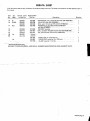
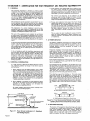
September 1973
FORM: OM-540
Effective with serial No. 71 .576983
MODEL/STOCK NO.
SERIAL/STYLE NO.
OWNERS
MODEL
STOCK NO.
SCE- 1 A
040 105
SCE-2A
040 107
SCE-3A
040 109
SCE-5A
040 256
SCM-lA
040 104
SCM-2A
040 106
SCM-3A
040 108
SCM-5A
040 255
DATE PURCHASED
MANUAL
MILLER ELECTRIC MFG. CO.
APPLETON, WISCONSIN, USA 54911
NWSA CODE NO. 4579
US
ERRATA SHEET
After this manual
was
printed, refinements
in
equipment design occurred. This sheet lists exceptions
to data
appearing
later in
this manual.
Item
Dia.
Part No. Listed
Replaced With
No.
Mkgs.
In Parts List
Part No.
Quantity
Description
CONTACTOR, size 1-3/44 pole (Eff with S/N HE8O1 243)...
14
W
034820
034 909
16
GS,WS
035 601
003 538
VALVE (Eff with S/N HF854924)
033 050
003 539
039602
035 493
19
012 602
012 640
41
033410
034 910
42
034 825
*034911
COIL, valve 115 volts ac (Eff with S/N HF854924)
RECEPTACLE, grounded-twistlock 3P3W (Eff
with S/N HE793827)
HOLDER, fuse-plug
COIL, contactor 115/230 volts (Eff with S/N HE8O1 243)....
KIT, point-contact (Eff with S/N HE801243)
031 601
Deleted
17
99
RC1
C3
100
014 159
059 887
BE SURE TO
CAPACITOR, HF (consisting of)
CAPACITOR, metalfilm 10 uf 220 volts
CLAMP, capacitor 1 inch dia
2
-
Parts
PROVIDE1MODEL~
1
4
-
007 532
*Recomm~J~dSpare
1
Deleted
081 291
C3
1
AND SER IAL NUMBERS WHEN ORDERING REPLACEMENT PARTS.
OM-540 Page A
A
CERTI FICATE
NAME
OF
EQUIPMENT:_________________________ MODEL NO..
SERIAL NO._~________________________
This equipment has been
by
the Joint
iate
Industry
less than
established
by
10
microvolts
the
Federal
on
per
meter
at
on
the radiation limitations established
as
The
by
specified
welding equipment identified above
only
applicable
to
this model
for the purpose for which it
ance
with
the
Date
Installed.
manufacturers
as
was
the
conditions
Welding
mile, the
one
for
equipment
book
recommended
as
Machines found
to
rad
limit
allowable
maximum
of this type.
be
reasonobly
Federal Communications Commission,
in the instruction
expected
only
to
when in
provided.
CERTIFICATION
has been
outlined
in
the
intended and
instructi~ns.
of
Commission
Arc
test
the basis of these tests, may
USERS
structions
distance
a
Communications
stalled, operated and maintained
field
High Frequency Stabilized
Installations using this equipment
meet
under standardized
type-tested
Committee
DATE
is
installed
instruction
being
in
accordance with
book
furnished.
maintained
and
It
the
is
operated
specific
being
in
in
used
accord
TABI-E OF CONTENTS
Paragraph
No.
SECTION 1
1
1
1
-
-
-
INTRODUCTION
1.
General
1
2.
Receiving-Handling
Description
1
Safety
1
3.
1-4.
SECTION 2
2
2
2
2
2
2
2
-
-
-
-
-
-
-
1.
2.
3.
3
3
3
3
-
-
-
-
-
1
INSTALLATION
Primary Connections
Secondary Connections
Shielding Gas Connections
5. Con tactor Control
1
1
2
Receptacle
7. Manual Control Connections Of
1.
2
Sequence Control Function
3
3. Normal-Fast Start Switch
3
3
Automatic-Manual Switch
4.
5. Manual Control Of
Sequence
4
C
4
High Frequency Control
SEQUENCE OF OPERATION
4
Welding (SMAW)
Gas Tungsten-Arc Welding (GTAW)
2.
SECTION 5
4
MAINTENANCE
11
5-1. Maintenance Safety
5- 2.
5-3.
5- 4.
5- 5.
11
High Voltage Capacitors
Spark Gap
Spark Air Gap Adjustment
By-Pass Panel
11
11
11
TROUBLESHOOTING
SECTION 6
SECTION 7CERTIFICATION
FOR HIGH FREQUENCY ARC WELDING EQUIPMENT
23
7-1. General
-
2
2. Current Control
4. 1. Shielded Metal-Arc
7
2
FUNCTION OF CONTROLS
SECTION 4
-
1
Emergency Stop Switch Connections
Sequence C
6.
3- 6.
4
1
4. Water Connections
SECTION 3
3
Page No.
23
2. General Information
23
7-3. PowerService
7-4.
23
7
24
7
-
-
Welding Machine
5. Welding Leads
6. Wiring In The Vicinity
Of The
Welding
7-7. Grounds
7- 8.
Metal
7
Individual Installation Certification
-
9.
Building
7-10. Check List
PARTS LIST
Area
24
24
24
25
25
SECTION 1
~Dimensions
INTRODUCTION
Weight (Pounds
(Inches)
Height
Width
Depth
Net
Shipping
33-1/4
26-1/4
10-5/8
168
230
Figure 1-1. Specifications
1-1.
GENERAL
1-4.
This manual has been
izing personnel with
SAFETY
Before the equipment is put into operation, the safety sec
tion at the front of this manual should be read completely.
This will help avoid possible injury due to misuse or improper
prepared especially for use in familiar
the design, installation, operation,
maintenance, and troubleshooting of this equipment. All
information presented herein should be given careful con
sideration to assure optimum performance of this equipment.
welding applications.
following definitions apply to CAUTION, IMPORTANT,
and NOTE blocks found throughout this manual:
The
1-2.
RECEIVING-HANDLING
CAUTION
Prior to installing this equipment, clean all packing material
from around the unit and carefully inspect for any damage
that may have occurred during shipment. Any claims for loss
or damage that may have occurred in transit must be filed by
the purchaser with the carrier. A copy of the bill of lading
and freight bill will be furnished by the carrier on request if
occasion to file claim arises.
U
I
Installation, operating, and maintenance procedures.
practices, etc., which will result in personnel injury or
loss of life if not carefully followed.
I
I
When requesting information concerning this equipment, it is
that Model Designation and/or Stock Number and
Serial (or Style) Number of the equipment be supplied.
IMPORTANT
essential
I
I
1-3.
Installation, operating, and maintenance procedures,
practices, etc., which will result in damage to equip-
DESCRIPTION
ment.
U
U
These
Sequence Controls are specifically designed to be used
in conjunction with an electric current controlled welding
power source. These Sequence Controls provide five different
sequences for either automatic or semi-automatic operation
of the various welding processes. The function of each
sequence is described in Section 3, Function of Control, in
this manual. The SCE Models are equipped with electronic
timers in sequences B, C, and D. The SCM Models are equip
ped with mechanical timers in sequences B, C, and D.
SECTION 2
2-1.
-
NOTE
Installation, operating, and maintenance procedures.
practices,
Refer
to
and
the
of the
Installation Section
(Primary
correspond with the primary power supply voltage of the
welding power source. Refer to Figure 2-1 for positioning of
the link for the required operating voltage.
Connection para
power source Installation, Operation
Manual for connecting the primary power
Maintenance
to the welding power
I
Control is connected to this block. The jumper link must be
connected for the primary power supply voltage that will
welding
supply
emphasize.
INSTALLATION
PRIMARY CONNECTIONS
graph)
etc., which it is essential to
I
source.
On the SCE/SCM-5A the control transformer which provides
primary power to the control is located in the welding
the
On the
SCE/SCM-1A, 2A and 3A Models, inside the cabinet
on the lower right corner above the control transformer, is
either a three or a five pole terminal block with one Jumper
link attached. The primary power supply to the Sequence
power
2-2.
source.
SECONDARY CONNECTIONS
(Figure 2-2)
230/460 VOLTS
the Installation Section (Secondary Connection
of the welding power source Installation, Opera
tion and Maintenance Manual for proper weld cable size.
Refer
to
paragraph)
~
460
230
The secondary terminals on the Sequence Control are labeled
ELECTRODE and WORK. Connect the electrode holder
cable to the terminal marked ELECTRODE and the work
cable to the terminal marked WORK.
208/230/460 VOLTS
_u ~
208
_u
230
460
2-3.
230/380/460 VOLTS
SHIELDING GAS CONNECTIONS
These
labeled
connections
are
IN-GAS-OUT.
(Figure 2-2)
located on the front panel and are
The connections have a right hand,
5/8-18 female thread. Connect the hose from the shielding
supply to the connection labeled IN. Connect the hose
gas
230
380
from the electrode holder to the connection labeled OUT.
460
230/460/575 VOLTS
2-4.
VtATER CONNECTIONS
(Figure 2-2)
connections are located on the front panel and are
IN-WATER-OUT. The connections have a left hand,
5/8-18 female thread. Connect the hose from the water sup
ply to the connection labeled IN. Connect the hose from the
These
labeled
230
460
575
TA-040 107-4
Figure 2-1. Line Voltage Jumper Link Arrangement
electrode holder to the Connection labeled OUT.
OM-540 Page 1
EMERGENCY
2-6.
I~RT~1
If
a
portable
water
coolant
system
is
make the above connections, as possible
occur to the coolant system motor.
2-5.
CONTACTOR
CONTROL
Ures 2-3 and
used, do
damage
uences B, C, or 0. If it is desirable to connect an emergency
stop switch in the circuit, remove the jumper link that is
connected across the fourth and fifth terminals counting left
to right. Connect a normally closed switch to the terminals
from which the link was removed.
(Figure
2-2)
This two prong, twistlock receptacle,
trol facilities. Either a remote hand
used.
A
two
twistlock
prong,
provides
With the AUTOMATIC-MANUAL Switch in the AUTO
MATIC position, weld sequences B, C, or D may be inter
rupted at any time by opening the emergency stop switch.
Opening of this switch will initiate sequence E (post-flow
contactor con
foot switch can be
is supplied with the
or
plug,
(Fig
A five pole terminal block with two jumper links attached,
located on the inside lower left corner of the cabinet, pro
vides a means of emergency stop connections of weld seq
not
could
RECEPTACLE
STOP SWITCH CONNECTIONS
3-2)
Sequence Control.
time).
2-7.
MANUAL
QUENCE C
HIGH FREQUENCY
SWITCH
CONTROL CONNECTIONS
2-3 and 3-2)
OF
SE
(Figures
A five pole terminal block, with two jumper links attached,
located on the inside lower left corner of the cabinet, pro
vides
of external switch control of sequence C. To
external switch for manual control of sequence C,
remove the jumper link connected across the first and second
terminals counting left to right. Connect a normally open
switch to the terminals from which the link was removed.
a
means
connect an
CABLE TO OUTPUT
TERMINALS OF
WELDING POWE~
SOURCE
EMERGENCY STOP
JUMPER LINK
TA-040 107-2
Figure 2-2.
TA-OlO 566
Front Panel View
Figure
2-3. Terminal Block For External Switch
Operation
SECTION 3 -OPERATION
31.
SEQUENCE CONTROL FUNCTION
(Figure 3-1)
Sequence
Sequence
Sequence
A:
B:
as
follows:
Pre-flow of gas and water; adjustable
chanical time of 1/4 to 15 seconds.
me
Sequence
Start-current; adjustable control and timer
POST-FLOW OF
GAS &
pre-set magnitude of current and time.
Weld Current, adjustable control and timer
provide exact values of current and time.
Sequence can be manually controlled.
Sequence D: Final weld current; adjustable control and
timer are pre-set to determine magnitude
This Sequence Control is a five sequence automatic control,
designed for Gas Tungsten-Arc Welding (GTAW). The func
tion of each sequence is
C:
E:
and time duration of current at end of weld.
Post-flow of gas and water, adjustable me
chanical time sequence of 2 seconds to 3
minutes.
PRE-FLOW OF
& WATER
~
tA~
9
ST~RT
~
~C
V
WftD
I-,/7777777777/7/
/(((~/ /___________________
t7T~\
~
~
DI
FINISH
ISH
1
(((777/7(7
\~
TIME
TA-040 107-6
Figure 3-1. Sequence Time Chart
Page 2
3-2.
CURRENT CONTROL
(Figure 3-2)
3-3.
NORMAL-FAST START SWITCH (SCE/SCM-1A and
2A)(Figure 2-2)
The welding current for each sequence is governed by the
setting of the three Amperage Controls which are labeled
Start Weld Amperage Control (sequence B), Normal Weld
Amperage Control (sequence C), and Slope Weld Amperage
Control (sequence D). The control dials are calibrated in
percent. These controls act as remote controls, in that they
are fine current adjustment of the Fine Current Adjustment
Controls on the welding power source. The STANDARDREMOTE Amperage Control Switch on the welding power
source must be in the STANDARD position..
This switch provides a choice of selecting either
fast start of sequence B (start weld).
A.
a
normal
or a
Normal Position
With the switch in the NORMAL position the starting current
will start at a value less than the setting of the Start Weld
Amperage Control, but will rapidly increase to the setting of
the Start Weld Amperage Control.
B.
Fast Position
With the switch in the FAST position the starting current will
the value of the Start Weld Amperage setting.
start at
Cu rrent Ad ju stme~
trols on the we Iding
power source must be in the one hundred percent
position for maximum control of the selected range.
A.
Start Weld
Amperage
Control
on
3-4.
Automatic Position
A.
With the switch in the AUTOMATIC
Normal Weld Amperage Control
(Sequence C)
This control is provided for selecting the normal weld current
value. The control is adjustable and can be set for any value
from the minimum to the maximum of the selected current
range on the welding power source.
C.
position, the Sequence
Control will operate automatically through all sequences with
the use of a contactor control switch connected to the Con
tactor Control Receptacle.
(sequence C) setting.
B.
(Figure 2.2)
This switch provides a choice of selecting either an automatic
or semi-automatic operation of the Sequence Control.
(Sequence B)
This control is provided for selecting the start weld current
value. The control is adjustable and can be set for any value
from the minimum to the maximum of the selected current
range on the welding power source. For a normal start the
control should be set for a value less than the normal weld
AUTOMATIC-MANUAL SWITCH
B.
Manual Position
range on the welding power source. For a normal finish the
control should be set for a value less than the normal weld
position, the timers of se
quences B, C, and D are removed from the circuit. However,
the weld sequence current value will be controlled by the
normal Weld Amperage Control on the Sequence Control.
Closing the contactor control switch will initiate sequence A.
Upon completion of sequence A the weld sequence will be
initiated automatically. The Sequence Control will continue
to operate in the weld sequence until the contactor control
switch is opened. Opening this switch will extinguish the
weld sequence and initiate sequence E (post-flow gas and
(sequence C) setting.
water
Slope
Weld
Amperage Control (Sequence D)
This control is provided for selecting the slope weld current
value. The control is adjustable and can be set for any value
from the minimum to the maximum of the selected current
With the switch in the MANUAL
time).
GAS AND WATER
POST-FLOW
TIME CONTROL
SLOPE WELD
NORMAL WELD
TIME CONTROL
VOLTAGE CHANGE OVER
TERMINAL BLOCK FOR
CONTROL TRANSFORMER
TERMINAL BLOCK
FOR EXTERNAL
SWITCH OPERATION
AND EMERGENCY
STOP SWITCH CONNECTION
TA-040 107-3
Figure 3.2. Control Panel
View
OM-540
Page 3
3-5.
MANUALCONTROLOFSEQUENCEC
Provisions
are
provided for manual timing of sequence C
intensity. To increase the intensity connect both links in the
position labeled DIRECT. To decrease the intensity Connect
both links in the position labeled AIR.
to
allow continuous
welding for any desired time. This is accom
plished by connecting an external switch into the circuit.
Refer to paragraph 2-7 for information on connecting the
external switch. The Sequence Control
functions auto
matically through sequences A and B. but the time duration
of sequence C is controlled by the external switch. Closing
the external switch will extinguish sequence C and initiate
the slope weld time (sequence D).
3-6.
HIGH FREQUENCY CONTROL
The
controlled
high frequency
coupling jumper links and the High
is
B.
With
the switch in the OFF position, high frequency is re
moved from the weld circuit. This method is recommended
for Shielded Metal-Arc Welding (SMAW).
C.
(Figure 2-2)
Direct-Air
through the Direct-Air
Frequency Switch labeled
Coupling
D.
Located on each side of the high frequency panel are three
terminals and one jumper link. The position of the links are
labeled DIRECT and AIR. These links provide facilities for
connecting the high frequency transformer for either direct
or air coupling which governs the amount of high frequency
SECTION 4
4-1.
Welding,
check and
Continuous Position
With
the
switch
or
adjust
the
shielding
gas and water sup
Check that secondary connections
paragraph 2-2.
Check that
sdcondary
connections
described in
are as
4.
paragraph 2-2.
3.
are
as
described in
Determine
the type of welding Current required
DCSP or DCRP) and position the Polar
ity Switch or Selector Switch on the welding power
source
plies.
2.
Tungsten-Arc Welding
Con
3.
shut-off the
fre
position high
(GTAW).
whether
Disconnect
CONTINUOUS
the
method is recommended for AC Gas
2.
trols
1.
in
quency is induced into the weld circuit during all three weld
ing sequences or as long as the contactor is energized. This
SEQUENCE OF OPERATION
-
SHIELDED METAL-ARC WELDING (SMAW)
For Shielded Metal-Arc
as follows:
Start Position
With the switch in the START position high frequency is
induced into the weld circuit as an aid in starting the arc.
When a welding arc is established the high frequency will
automatically shut-off. This method is recommended for dc
Gas Tungsten-Arc Welding (GTAW).
START-OFF-CONTI NUOUS.
A.
Off Position
(AC,
accordingly.
Place the Current Range Switch on the welding power
in the desired current range.
source
Determinal the type of welding current required (AC,
DCSP or DCRP) and position the Polarity Switch or
Current Selector Switch
on
the
welding
power
5.
Rotate the Fine Current Adjustment Control on the
power source to the maximum position.
welding
source
6.
accordingly,
Rotate
the Start Weld Amperage Control, Normal
Amperage Control, and the Slope Weld Amper
age Control on the Sequence Control to the desired
setting.
Weld
4.
Place the Current Range Switch on the welding power
in the desired current range.
source
5.
Adjustment Control on the
position.
7.
Rotate the Normal Weld Amperage Control (sequence
on the Sequence Control for the approximate per
centage of weld current desired within the range selec
ted on the welding power source.
8.
Rotate the
welding
6.
Fine Current
power
source to
C)
Place the Automatic-Manual Switch in the MANUAL
position.
8.
On SCE/SCM-1A and 2A Models, adjust the Start
Weld Amperage Control to approximately the same
setting of the Normal Weld Amperage Control setting.
9.
On SCE/SCM-1A and 2A Models place the NormalFast Switch in the desired position according to the
welding application.
On SCE/SCM-1A and 2A Models, place the NormalFast Switch in the desired position according to the
welding application.
9.
7.
Place the Automatic-Manual Switch in the MANUAL
position.
the maximum
10.
Place the High Frequency Switch in the START posi
tion for dc welding and in the CONTINUOUS position
for ac welding.
Adjust the shielding
gas and water pre-flow and postflow timers for the desired time setting.
Table 4-1
Guide For Selecting Electrode For Gas Tungsten-Arc Welding
PURE TUNGSTEN
Electrode Dia. (In.)
10.
11.
12.
13.
Place the High
Frequency
Switch in the OFF
position.
Connect a normally open switch into the Contactor
Control Receptacle.
Place the On-Off Power Switch
source to the ON position.
Close
the
Contactor
Control
on
the
welding
Switch and
power
commence
welding.
14.
Readjust the controls
as
necessary
for
proper weld
condition.
4-2.
GAS TUNGSTEN-ARC WELDING (GTAW)
For Gas Tungsten-Arc
as follows:
1.
Welding, check
and
adjust the controls
Check that shielding gas and water Connections
described in paragraphs 2-3 and 2-4.
CURRENT_RANGE
ACHF-Argon
DCSPArgon
DCSPHelium
15
Up
to 20
10 to 30
15 to 50
20
to
20
to
70
25
to
30 to 90
.010
Up
.020
.040
to
15
Up
to
70
60
1/16
50
to
125
50
to
135
60 to 150
3/32
100
to
160
125
to
225
140 to 250
to
1/8
150
210
215
to
360
240 to 400
5/32
190 to 280
350
to
450
390
to
500
3/16
250
450
to
720
500
to
800
1/4
300 to 500
720 to 990
800
to
1100
to
350
1% AND 2% THOR IATED TUNGSTEN
.010
Up
to
20
Up
to
25
Up
to 30
.020
15
to
35
15
to
50
20
to 60
.040
20
to 80
25
to
80
30
to 100
1/16
50
to
140
50
to
145
60
to
3/32
130
to
250
135
to 235
150
to
260
1/8
225 to 350
225 to 360
250
to
400
5/32
300
to
450
360
to
400 to 500
3/16
400
to 550
450
to 720
500
to
800
1/4
500
to
720 10990
800
to
1100
450
160
are as
800
TA-90
Page
4
190-3
11.
12.
13.
Select the proper size tungsten for the welding applica
tion from Table 4-1.
14.
Connect a normally open switch into the Contactor
Control Receptacle.
15.
Place the On-Off Power Switch
the ON position.
the
on
welding
the
Close
switch
control
contactor
and
commence
welding.
Readjust the controls
as
necessary for proper
welding
condition.
power
source to
SCE-IA, 2A
SCM-IA. 2A
CHART
SEQUENCE TIMER FLOW
p.
S
1
Switch
in
Manual
S
2
Switch
in
Normal
Start
S
3
Switch
in
Start
Position
picks
drops
-
u.
d.c.
-
up
out
Position
Posit ion
Power Switch On
Control Transformer
I
~oltage
Control
Energized
TO 5
p.u.
Begins
Time
Gas & Water
Available
On
a
Operator
I
Fan
On
On
p
Times Out~
~
On
PL4
TO 5
Gas & Water
Z
U
FL 4
Off
Closes Maintain Switch
RC 1
Thxough
I
CR1
I
I
H,F, On
Primary
(Continuous Position)
p.u.
Lfi
Contacror
w p.u.
CR2
O.C.V.
Closes
W 1
P1,2
On
p.u.
R4
~
CR
CR3
Welding
d.o.
Welding
and
at
-
CR 2
-
I
Off
1-IF.
d.o.
d.o.
(Continuous
Primazy
W
Position)
Sequence
Continuous
Flow
Position
Start
Position.
CR6
Start Time and I-I.E.
Off
Start Control
Start Rheostat Control
-
Relay
Relay
Weld Terminated
I~1
I-
R4
C
CR 6
-
Weld Rheostat Control
CR 7
-
Weld and
CR 8
-i
I.
o~
Relay
~onsactot
W
PL2
Control
Relay
Secondary Voltage Sensing Relay
-
d.o.
Opens
d
Point A in
Gas and Water Control
CR 4
CR2
Times Out
Opesator
Operator
TD1
TD 5
as
Point B when H.F. Switch is in
CR 1
CR 5
Time
established
do.
CR 3
p.u.
Fast
Posit ionl
Eatablished
(Start Positionl
TD5
arc
Off
HF,
Begins
pu.
in
(S2
d.o,
CR4
I
CR5
p.u.
I
d.o.By
d.o.
Chart when II.F. Switch is in
CR4
CR1
TD5
On
p.u.
Operative
(Weld I~eosat)
CR3
PL4
Start
I
On
Position)
I
Gas&Wate.r
CR6
p.u. (No Effect
in Manual
AvaiLable
_______________
TO 1
p.u.
I
Inoperative
CR 9
-
Slope
Relay
Time Control
Relay
Slope Rheostat Control Relay
Stop Sequence Relay
~~5
2
FL 4
Off
Gas & Watet
Off
Figure 4-1. SCM/SCE.1A,
2A
Sequence Flow
Chart
-
Si Manual Position
OM-540 Page 5
SLM-lA~
ICE-IA.
2A
SEQUENCE TIMER
2A
p~u.
FLOW CHART
S
1
Switch
in
Automatic
S
2
Switch
in
Normal
picks
dtops
-
d.c.
-
up
out
Position
Start
Position
Power Swiich On
Control Transformer
Energired
f
Control
.CR S
Point E when S 2 Switch
at
Is
operative during preflow.
operative after Primary
a
Gas
Stare
CR S
In Normal Position and R 3
Contacrm
pulla up.
Operator
I
P14
p.o.
Time
Beguts
Fan
On
On
~
TD S
Water
Off
p.u.
~1
TOS
On
Point 0 when S 2 Switch is io Past
at
p.u.
Position and R 3 is
I
I
Gas& Water
Voltage
Available
~
Times Out ~ Of f
.~.
-...-,
iomentary
Through RC 1
Closes
Operation of
Switch
at
Closed Switch
Normally
a
TE 4 will stop the Sequence
in the Weld
polor
Sequence.
at
any
Control
will revert to Position A of the Flow
p.o.
Chart,
CR1
TD1
d.o.
CR2
Pee
Begins
by
Released
p.o.
flow Time
Operator
TO 1
fi.j~mes
T02
p.o.
Regina
Starr
itself
Through
CR 9
TOS
Gas & Water
Our
B
~timary
H.F.On
(Continuous
Arc established
Coorlnuous
at
this
when H. F.
point
Switch
in
Start
position.
Position)
Time
Circuit
Open
coltage
Available
ii
WI
Closes
CR3
p.u.
NOTE:
II
CR4
CR5
pa.
Position and
On
H.P.
TD 2
polls
op ood
begins
of Plow Chart wheo H.P. Switch
p.o.
I
Start
time
is
at
in
Point
Continuous
Point C when H.P. Switch
at
is
io
Positioo.
__________
(Start
R 3
P1. S
On
Operative
Rheostat).~5
(Start
A
Welding
Position)
~
c
Established
B
CR3
d
.0.
CR S
I-.
I
p.o.
Regina
Start
P11
TD2
Operator
-
(Start
CR3
-
Position)
CR4
Start Time and H.P.
CR 5
Start Rheostat Conuol
Time
p
CR 6
TO 2 Timea Out
Gas aod Water Coorrol
Relay
Secondary Voltage Sensing Relay
Weld
Relay
Relay
Relay
Weld aod Slope Time Control Relay
Slope Rheostat Control Relay
Stop Sequence Relay
CR 9
Begins
Start Coorrol
Weld Rheostat Control
-
CR7
PCI
CR6
T03p.u.
Relay
-
Off
H.P.
On
Control
CR2
I
CR 9
Ott
p.ii.
I
Time
F
TO 3
Times Out
CR5
R 4
d.c.
(Weld Rheostat)
Operative
Switch
Inoperative
P1
R 3
Off
(Start Rheostat)
Operarioo
Connected
to
2 & 3 of TE 4
Provides Manual Coorrol of Weld Time Duration
CR7 p.o.
CR6
d.o.
TO4
Time
I
R 1 Operative
(Slope Rheostat).~
Times Out
(Weld Rheostat)
P13
On
p.o.
I
TD 4
Inoperative
I
CR9
p.o.
Begins Slope
S
R4
I
I
I
PL2
Off
F
S
CR 9
P.y.
5
5
5
TD1
P13
CR2
H.P.
d.o.
Off
d.o.
B
fContlnuoos
s
TD 5
p~
d.o.
Begins
Time
~onractor
do.
B
Weld Terminated
Opem
5
S
Times Our
d.o.
d
W
W 1
TO 1
TO 3
I
Primary
Position)
TO 2
CR 7
Off
a
s
P1 4
Off
Gas & Water
Off
.0.
I
CR8
4.0.
I
R S Irrnperarloe
(Slope Rheostat)
T04
d.o.
Ch
d.o.
Make
H.P.
Ready
TOl
W
P13
Figure 4-2. SCM/SCE~iA. 2A Sequence Flow Chart
Page 6
-
in
Dotted lines show flow sequence with
Position.
H.F. Switch in
p.u.
w
P14
On
do.
On
Welding
S
Contacror
pa.
on
Locks
Si Automatic Position
SCM-3A
SCE-3A
SEQUENCE TIMER FLOW CHART
p.s.
Q4 MANUAL POSITION
SWITCH S 1
-
do.
POWER SWITCH
-
picks
drops
rip
out
0N
CONTROL TRANSFORMER ENERGIZED
CR5
I
Control1vouage
pu.
I
I
Gis & Water
Available
TO S
pu.
Begins
Time
I
Make
R 3
Ready
Operative
Operator
CR1
FL 4
Times Out
Off
Maintained
Cloas
Switch Thzou h RC
a
TD
~
0f1
0n
I
I
Gas & Water
(Star Rheostat)
PL 1
Fan
FL 4
0n
1
p.s.
I
TO 1
p.s.
Begins
Time
H. F
Primary
I
CR2
0n
.
Switch S3
Contactor W
p
Times Out
Manual
Make
in
TO S
d.o.
On
-0
Closes
Wi
(No Effect
~~1
FL 4
Gas & Water
(Continuoul Position)
TO1
Pu.
a-
when
O.c~.V.
ready to pull up TO 2
welding arc is established
Welding
Position)
arc
P.S.
CR 4
pu.
0n
Start Position)
Welding
CR3
d.o.
CR4
d.o.
H.F.
Off
A
at
point when
position.
thu
Continuous
Dotted lines show flow sequence with H. F.
CR3
Switch is
HF.
established
H.F. Switch 53 ii in
Avatlable
Start
posItion.
Established
(Start Position)
FL
TO2
1
Start
Begins
0n
p.u.
Time
TD 2
Times Out
CR1
-
CR2
CR6
PL2
CR 5
R 4
Operative
(Weld Rheostat)
d.o.
FL 1
R 3
Off
...s
I
Inoperative
Relay
Secondary Voltage Sensing Relay
CR4
Starr Time and HF.
CR S
Start Rheostat Control
CR6
-
Weld Rheostat Control
CR 7
-
Weld and
CR 8
(Start Rheostat)
CR1
Gas and Waler Control
CR 3
p.u.
Slope
Start Control
Relay
Relay
Relay
Time Control
Relay
Slope Rheostat Control Relay
Stop Sequence Relay
CR 9
do.
Operator Control Relay
I..
By Operator
I
U
:6
CR2
TD1
Primary
do.
d.o.
Contactor
HF.
d.o.
W
0ff
(Continuous
Position)
W 1
TD 2
d.o.
CR 6
PL2
d.o.
CR5
PL2
p.u.
Off
Inoperative
(Weld Rheostat)
Make
Ready
PL 1
R3
Operative
(Stan Rheostat)......
TO
p.u.
Begins
Post Flow Time
TDS
Times Out
FL 4
Off
Gas & Water
-ncr-
Figure 4-3. SCM/SCE-3A Sequence Flow Chart Si In Manual Position
-
OM-540 Page 7
M-3A
Si
ni.L-3A
SLQSENCF 1 OdER FLOW CHART
SWITCII 5 I
IN AVTOhIATIL
POSITION
pnksu r
p.o.
R)HER SWPICII OS
J.
o.
.
dropt
CONTROL TRAhSF~MER Rt1EHCIZEO
CO S
Control
p.u.
G~Lstei
Voltage
Available
Make
H 3
Ready
Opetarice
Begins
Os. & Water
(Stan Rheostat)
FI!4
p.c.
Tune
TD
p
Pan
-On.
On
FL 4
~
Times Out
Of)
-
FL 1
TDS
SOn
Operator
~%_~__
will
pu.
tlntma lIp Ccrcd
a
TE 4 will stop tin
at
peutt
CR I
of
Operation
Momentary Switch
Through bCl
the
in
truce
oe
se
position S of
to
uuoi
quccic at
Id sequence.
snip
Control
lie FInn
r
Chart.
S
CR0
do.
CR1
P.O.
Locks
Operator
Released by
101
on
hsell
CR3
Through
p..
Prellow Tune
Begin.
S
ID I
Ca. & Waier
TO S
TiniesOui
H.P.
T02
tn
(Switch
Cont
Peimar1,
C
H
Wnlding
Contractor pu.
H. F.
polls up
and
of Flow Chart when H. F.
and
position
Srarr
at
begins
Snitch
tune at
is
Circuit
ic
is
Ccnticucus
pu.
CR4
P.O.
Of!
H.P.
Stan Time
Switch
Start
S
CR 1
-
H
CR2
-
H
CR3
-
Cn 4
-
in
Position
Operator
lAnes Out
Relay
Relay
Secondary Voltage Sensing Relay
Sraat Time and H. F.
Starr Rheostat Control
Weld hheoear Control
-
CR1
J
R
C,
Weld Time
Coctrcl
Oss and Water Control
CBS
CR6
TD3p.u.
Regina
icy.
de
102
P1
POSH
A;o Established
4j2_kE~)
102
Regma
position.
scqunocrw oh
Stari~
(Stan Position)
WeMmg
PL~l
in
P.
coltsg.
CR3:
Oc
H.P.
CO
his poini whnni H
Acailable
yowl
point C when H. F. Switch
CR3
Swnch 5 3
at
Contlouous
in
position.
on
in
Doned hires show flow
Open
ID 2
estabh,hed
arc
Swiich 53 is
00002
Position)
ROTE~
llc
3
~
Starr Time
Begwrs
in
IL 4
d.c.
-
Start Ccorrol
Relay
Relay
Relay
Weld and
CR 8
-
CR8
-
Slope Time Cnnttcl Selay
Slope Rheostat Control Relay
Srop Sequence Relay
p.o.
CR 5
04
do.
(Weld Rfstnsrat)
PLI
Operative
3
R3
ORf
leopetarioe
(Stan Rheostat)
ID 3
Times Out
ltinh
TB 4
w
-
Connected 1 & 2)
Switch operation
connected to 2 & 3
manual control o) weld
CR7
CRR
124
Remains
do.
hegms slope
P12
CR8
PL53
Off
p.o.
On
p.R.
BS
Open
Rh
124
htoperar foe
lIme.
CR9
0ft
dv,
(Cnsrlitoous
d.n.
1
Peimoey
W
Cootactoe
Weld Teemonared
d.?.
Pnnitlnn)
1D2
Begins
0
pu.
P13
CR2
H
(Slope Rfiecsrat)4
I
H.P. Off
I
provides
S
Opera rice
Oor
I
121
I
o) TE4
duration.
p.c.
CBS
(Weld Rfreosrat)
ume
do.
ton
FInn Tone
123
I
125
Times Out
I
CR5
CR8
P.O.
do.
104
do..
CR8
do.
Make
Ready
H.P.
101,
H
PL3
Rb hinperarive
(Slope RRt~af)
Make
Ready
B 3
OperatIve
____________
P11
P1.4
~ff
Gas &
(bract Rlrensasr)
Wares
011
Figure
Page 8
4-4. SCM/SCE-3A
Sequence
Flow Chart
-
Si In Automatic Position
Ii
SCMSA
sUE-IA
SEQUENCE TIMER El
r)W (hART
Manual PoSition
2 & 3 for Switch
Operation
Switch)
Start Position (H. F.
0N
POWER SWITCH
I
CR S
TD S
pu.
I
R 3
I
Operative
(Start Rheostat)
Energize
Gas & Water
Lights
Flow Starts
CR 9
pu.
PL 1
p.u.
Stops
I
PL4
Circuit Closed
By.Pass
by.pass
1
before Hl.F. is
time
1
on.a
off before
(Control Safety Relay)
Make
CR 2
bypals
Gas&
Water Ott
CR 2A
CR16
pu.
Time
W
CR I
p.u.
CR U
p.u.
Conta :tor
Welding
Ire
TDI
pu.
0n
HF.
to
CR 13
CR2B
pu.
d.o.
1fF.
Off
Make
Times Out
Energize
Begins
TD 2
Times Out
-
CR 2A
-
CR 25
-
CR 3
-
CR4
CR 5
-
control
relay
Interlocking control relay
Control relay
Control relay
Overvoltage sensing relay
H.F. signal relay
Control relay for start rheostat
Welding
-
CR 8
-
CR 9
CR 10
-
CR 11
-
CR 12
CR 13
CR 14
CR 15
-
CR 16
-
CR 17
-
Slope
relay
Arc
CR
Goes
d.o
O~it
R 3
Ino~erative
(Released by Operator)
~1
CR2A
do,
do.
do.
d.o.
Extinguil
for weld rheostat
ed
CR11
d.o.
I
d.o.
CR 10
d.o.
d.o.
CR6
PC2
relay
for slope rheostat
Safety control relay
H.F. time delay relay
Differential voltage sensing relay
Contactor drop out time delay relay
Interlocking control relay
Time delay elay (or CR 2 inrerlock
Start 165 volt control relay
HF. control relay
HF. By Past Time Delay Relay
do.
Off
d.o.
Voltage
Reducer
Open
p.u.
pu.
I
1
TI) 5
CR 9
p.u.
p.u.
CR 16
U
a.
Begins
p.u.
CR 17
CR14
CR2
I
TD6
CR12
control
Control
do.
CR28
I
CR 7
& CR 11.
I
TD1
Primary
Control
Delay
HF.
I
CR 1
W
-
to
hF.
pu.
Operative
)
Contactor
CR 6
Ready
Time
I
Fl. 1
CR 2
do.
After Time
TI) 1
TD2
CR6
Lights Up
R4
Operator
CR 14
-1
PL 2
p
-
TDI
Closes
W 1
Lights Up
PU
Delay
-
p.u.
Esrabli.ihed
By-Pass Open
CR 1
pu.
I
Timer,
d.o. After
Time
CR28
RC 2)
Couttactor,
TI) 6 Times Out
CR 17
Ready
Energize
Up
Energize
-
I
Make
PL4
Lights
CR 2A
-
opens.
I
CR 10
to
insure
TI) I
to
Ready to Enet
gize High Frequency
short
I
BeginS
Ready
to
itself.
and PL 3
Make
closed
by Operator through
pu. (Held Closed
I
80 VOC Available
I
TI) 6
ott
of CR 17 insures
delay
H.F.
TDSd.o.
lockt
NOTE:
Goes
p.u.
Circuit
Opens
H.F.
Out
d.o.
delay
nine
CR 2
Contactor
~
CR 10 insures
CR9
(provides
pu.
short
CR 17
Gas & Water
Flow
I
I
CR 14
pu.
Continuously
I
I
CR2
I
CR 10
TI) 6 Motor Runt
Up
Times Out
Ready
Make
so
TI) S
I
I
PI. 4
pu.
I
I
Suit
80 Volt Position)
(Starr
S2
up
druipt
-
in
ha
pt
p.::.
Switch Si
Time
By
Pass
Closed
relay
TD S
CR5
Timm
R4
p.u.
Out
Inoperative
R3
Operative
Gas & Water
Shuts
Off
PL 4
Goet
Of
Figure
4-5. SCM/SCE-5A
Sequence Flow Chart-Si
In Manual Position
OM-540 Page 9
sCM-IA
SCE-5A
SEQUENCE TIMER
FLOW CHART
picks
drops
p.o.
Switch
Si
Link
&
1
in
A atoms tic
for
2
80
S2
Position
TDt
pu.
(H.
F
0N
PL 4
pu.
I
R3
Operative
(Start Rheostat)
P
I
Gas & Water
TO 6
Flow Statti
Motor Runs
CR 10
CR 9
pu.
time
CR 17 pu.
I
Circuit
Opens
Stoll~.
H.P.
Pass Circuit Closed
By
NOTE
PL 4 Goes
CR 10 insures
Out
by
Make
pass closed
gize
before H.F. is on.a short
time
delay of
lady
HF. off before
Momentary
Through RC 2
1~
CR2
Ecer
to
Make
High Frequency
Ready
through
by-pass
-
CR 28
TD5
d.
do.
CR 1
d.o.
PL4
by Operator
o.
Gas
CR2B
p.u.
T01
p.o.
CR 14
pu.
p
Ready to
Energize High Ere
13
Lights Up
after
d.o.
Delay
TimesOur
TDJ
Make
to
relay
control
relay
Time
Ready
Energize CR
&Water
TO 1
-
Overvoltage sensing relay
HF. signal relay
Control relay for starr rheostat
-
CR 5
Make
CR9
CRIB
Control
-
CR3
CR 2A
Energize
Interlocking control relay
Control relay
-
CR 2A
Switch
Open
-
Operator
CR 1
opens.
CR 2
Circuit Available
CR 9
so
CR2- CR2A
p.u.
80 VOLTS
pu. and Locks
itself
on
to
CR2 locks
itself)
ott
CR4
CR 1
delay
insure
3
(Control Safety Relay)
OVER WORK
Closes
TO
CR 17 insures
WELDING TORCH PRESET
Operator
so
and PL
Contactor
Flow
pu.
)Ptovides short
Gas & Water
PL 1
CR14
pu.
Continuously
Times Out
TD 5
up
out
Switch)
I
Lights
I
Make Ready
to Energize
o.
Position)
Volt
POWER SWITCH
CR3
d.
Timer
(Start
Start
Position
CR16 p.o.
quzuCy Contactor,
H.P. Timer&CR11
On
High Frequency
HF.
~p.u.
CR11
Result of H.F.
(Secondary Voltage Drops as a
Arc. Differential Voltage Pulls Up
~
P
CR12
1
Time
w
pu.
I
Contacor
~.u.
TD2
Begins
Time
PL 1
Lights Up
II
TO 6
Times Out
CR10
Welding
Arc Established
TD2
TmmosOut
TD3
CR 17
I-I.E.
do.
After Time Delay
BeginaTmme
CR6p.u
I
B 4
CR
Arc
-
CR 10
-
Safety
relay
relay for slope rheostat
relay
delay relay
Differential voltage sensing relay
Contacror drop out time delay relay
Interlocking control relay
Time delay relay for CR 2 interlock
Start 165 volt corttrolreIay
N.E. control relay
N.E. By Pass Time Delay ReLay
CR 11
CR 12
-
CR 13
-
CR13
control
H.F. time
-
-
CR 17
~i 1 Goes Out
Inoperative
B 3
Switch
Operation
Outage
Connected
TD4
CR7
P~U
BeginaTime
CR10
CR 6
p.u.
pu.
do.
PL 2 Goes Out
PL 3
t.U.
Remains
Control.
Tinner TO 2~&R3
Start
Operative
4
R4
CR7 Locks
CR S
Lights
WeldCycleReverts
to
Open
Through
on
Itself
WI
Inoperative
Times Out
On
Approximately
40
Cycles
CR 9
Arc Re-established
d.o.
CR4
do.
I
I
d.o.
cLot
d.o.
CR2
TO S
Welding
Arc
d.o.
Begins
CR 2A
pu.
P
I
d.o.
TD 1
d.o.
Time
I
TO 6
CR.
1~
d.c.
I
I
PL 3
CR 16
Goes
~
d.o.
TO 2
d.o.
d.c.
I
Out
CR11
TD5TimesOut
H.F. Off
I
By-Pass Open
p
__p
I
2
Gas & Water
Shuts Off
Ready
For HF.
CR 17
I
By-Pass Closed
d.c
CR2
p.u.
Goes
Out
Figure 4-6. SCM/SCE-5A Sequence
Make
P1. ~
I
I
CR 2B
-
CR3
CR 10
10
2 & 3 of TE 4.
3 pu.
CR4
Page
to
Provides Manual Control of Weld Time Duration.
less)
or
CR B
H.P.
CR 9
for weld rheostat
relay
control
Slope
Weld Rheostat
Tb 3 Times Out
(One cycle
PL2LightsUp
1
CR 5- d.o.
Operative
Control
Control
CR 16
Off
By-Pass Open
Unintenrior~al
-
CR14
,
d.o.
-
CR 7
CR 8
CR 11)
~
Begins
TO 6
CR 6
T03
do.
TD4
P
d.c.
CR7
do.
Voltage
Flow Chart
Reducer
-
d.c.
Open
Si In Automatic Position
CR5
CR8
pu.
d.c.
R3
R5
Operative
Inoperative
MAINTENANCE
SECTION 5
5-1.
MAINTENANCE SAFETY
5-4.
reiunr.]1
To
readjust the spark air gaps, proceed
A.
Loosen
Be
sure
the branch circuit, or the main disconnect
switch has been opened before attempting any inspect
B.
Place
ion
or
C.
performing
source
or
switch
on
the
any work inside the
welding
Placing
sequence control.
the
power
(A)
screw
follows:
Apply slight
(Fig. 4-1)
both sides.
.008 inch feeler gauge in spark air gap
an
gauge is held
power
on
as
against spark point (B)
the two points.
pressure
area
so
(C).
feeler
firmly between
the
welding power source in the OFF posi
tion does not remove electrical power from the switch
terminals.
5-2.
SPARK AIR GAP ADJUSTMENT
0.
Tighten
screw
(A).
HIGH VOLTAGE CAPACITORS
These capacitors require no attention and are rarely a source
of trouble. A defective capacitor, however, is evident usually
the
by
housing or evident of oil leakage in certain cases. Any
repair shop can readily determine the condition of
capacitors. (If one of the high voltage capacitors should
fail, operation may be continued with one capacitor until a
local radio
the
can be secured.I In order to prevent excessive over
the remaining single capacitor, the spark gap point
should be reduced to about .004.
new
one
load
on
setting
5-3.
SPARK GAP
The
spark point and air gaps can be inspected by opening the
Sequence Control. The spark air gaps are factory
set at .008 inch. It will be necessary to readjust the spark air
gap setting due to extended operation. Readjustment of the
spark air gap is also indicated when intermittent operation of
the high frequency is noted. Usually this occurs when the
spark air gap setting has increased in excess of .012 inch.
door of the
TA-020 623
Figure 5-1. Spark Air Gap Adjustment
5-5.
~ning
BY-PASS PANEL
The purpose of the by-pass panel is to reduce the high fre
quency feedback into the transformer of the welding power
source. A defective capacitor in this circuit would reduce
of the spark & r gaps d ue to n ormal ope ra
tion, may, if not corrected, increase the loading of the
high voltage, capacitors, thus contributing to their
premature failure. Cleaning or dressing the points is
high frequency output and might be evident by loss of oil
from the capacitor case. If in doubt as to condition of the
capacitors, have them checked at a radio repair shop. The
resistors in the circuit would show evidence of failure if they
recommended as the material at the gap area is
tungsten. The entire point should be replaced when
the tungsten section has disappeared.
not
are
.
SECTION 6
Failure in this circuit is
cracked.
pected only
as a
rare
and would be
sus
last resort.
TROUBLESHOOTING
-
The data listed
here, discusses some of the common problems which
may occur in this sequence control. A little thought will probably
solve the problem through the information provided.
If after checking the following data the trouble has
died, it is recommended that a serviceman be called.
The
during troubleshooting.
not been
reme
It is recommended that the circuit diagram be used for reference
been
assumption of this data
achieved
proper welding condition had
trouble developed. In all cases of equipment
until
malfunction, the
strictly followed.
is that
manufacturers
TROUBLE
Normal
output.
a
recommendations
should
be
REMEDY
PROBABLE CAUSE
No
high
Incorrect spark air gap.
Check
setting for .008 inch.
frequency.
High frequency switch
Shorted
Normal
output.
Low
high
in off
position.
high voltage capacitor..
Check switch position.
Replace capacitors.
Incorrect spark air gap.
Check
High frequency
Check all connections for
for .008 inch.
setting
frequency.
leaks.
Incorrect direct-air coupling.
Check
that
both
links
high frequency leaks.
are
connected
for
the
same
coupling.
Erratic weld
current.
Poor tungsten.
Check tungsten and replace if contaminated.
Incorrect polarity.
Check polarity.
Incorrect
welding
cable
Poor ground
size
or
loose
Check for proper weld cable size (See
cable connections.
paragraph 1-2.)
Tighten all welding
connections.
at
workpiece.
Check
ground
connections.
OM-540 Page 11
TROUBLE
REMEDY
PROBABLE CAUSE
Contactor pulls in.
Adjust
Incorrect operating voltage of CR3 relay.
slider
R2 resistor
on
CR3 relay
so
pulls
in
on
open circuit voltage.
Weld
current
does not shut off.
Contactor does
pull in.
not
Adjust slider
when welding
voltage of CR3 relay.
Incorrect operating
R2 resistor
is initiated.
on
arc
CR3 relay drops Out
so
Check fuses.
Blown fuses in control circuitry.
PCI
32
~36~7
CR
C
MAI
TEl
52
T1
36
FO
LO~O~o-----------
B
:sEc.
~
L
I r~
--
44
I
r
~
B
72
,.,
A
~
LO_Z~o~o___s_______
IC
TE1
23OVr
W
~a3OV
WELDING
SEQUENCE
iii
~
H.
i~
III
16
I
22
~
ID
_____________
TE3lj~9
TIMER
I!(~TE2
~?
_____
\~ ~
____
61*
30V
;
h4
1ISv
3
EMERGENCY
~
RC3*
Ill
A
I
23
0000000 ~
00000
30
IA
230V1
::
I
_
MACNINE
1460V
B
I
460V~
.
44
3
~
II
251
I
14
14
145R1
14
26
____
CR1
~
1,1
2
PCI
~
2/1
233
3
CR5
M
I
~TP~LOCATED
CR9
C~~QQQj
WELDING MACHINE
CR6
0~
WELD
ID,
237
\52
~~o51CR~,PL
C-FAST
~j9
CR3
5
8,8
276
RF
29
ELECT
WORK
FILTERS
l_
0
CR
I
IR
~o.
Ir~i~Ii3i
RD
I
3,5031
V8
~
Ill
I
1231
CR9
PAIRS
IOPTIONAL-ESTRA(
_I
l_~:~J.
I
TWISTED
VOLTMETERS
I
b.NOPMALI
CR85 LOPE
CR~
I
/
CR4A
START
~+L
28
P7
236
I
20
Pt
~
T~
8,10
I
SIR
START
OR---
235
18
22
REV
IN
234
CR5
53
5
4
I?
21
2,14,15
HFO~_~
9
I
START
CR
220
221
1C3– ~
L__1T1___J 2~,~RFC
8
___________
T3
5
CR
CR31
SEQLI E NC E
1-
~
PRCFLOW-GSW
2- START
3- WELD
1+~~4
TEl2
SA
23
3
2A
256
2
TIME
TD2
I
TIME
3<
4-SLOPETIME
Al
5- PO5TFLOWGIW
~l~l
C
W
R7226
10
CR
8,19,90.20
8
~E~0
*Op1IONAL..EXIRA
WITH
t,JUI
~,
~
ELECTRODE
2
WORK
~PL
PC3
CR73
-
I
8,10,11
.6-In
-~
21,22,22
60
TO
RC9
U
REMOTE
72
34420
3
iT
13
61*
4
.91 .90
I
0000
-
20
000
251 4 209
000
-
ESTRAI
GROUND (WNT 1
B-BRASS
249
C
-
COPPER
(VI
(5)
2,4
44
2.9039460
21
.
CR
RHS-2
~PL
000000
CONTROL
IOPTIONAL
..(RE
37322
-
~
~WL
80
TE2
COM
0
16
II.
TE3
CR2
ws1
IS
31
245
7246207208
00000
C
Si
6
4T
Circuit Diagram No. CB.900 529-13C
Figure 6-1. Circuit Diagram For 200, 300 & 400 Ampere DC Arc Welding Power Source
Page 12
With SCE-1A
Sequence Control
3/ 32 2 3 44 20
000000
IT
87*
7
3730
4
20
23039460
0000
000
2T
245
0
TE2
/246207208
0
0
0
4T
12345
Circuit
Figure
6-2. Circuit
Diagram
For 200, 300 & 400 Ampere DC Arc
Welding
Diagram
Power Source With SCM-lA
No. CB-900 529-14C
Sequence Control
OM-540 Page 13
1.11:
3?
~
IF I
LO-~-O~y
~27 CWA~
12
44
7
45
Si
TE1
?30V,
4A0 V
I
WELDING
FM
j
20
MACHINE
I~
2 )OV,
SEQUENCE
460V
TIMER
~
38
D
_
D
L___
230V
32
~
SEC
1
L OO
B
S2
MA1
T~
43
C
C,R
~74
Dcz
N
___________
(0
Dc.
TE2
TE3~
DI
TI
,00U0000
1
87*
4
-
175v
-1~-
-11
~
E ME P GE NC
~
1
CR
V
0PTI0NAL~~
CR
*
~
EXTRAWITHRC3
RC3*
~T
,SRI
26
24~HUNT
\
2,l~,I5
-~----.-
-0
-ASTR
REV
2/1
M
I
CR5 START
~FF
1TP-LOCATEDIN
CR9
WELDING
TDl~CR4A
A
WELD
CRlO15~~
1~~III~~f
2141
tH7.cPL
6
5
I
218
~
CR6
220
CR31
SEOUL NCE
1-PREFLOW
3-WELD
TIME
TIME
5
ELECT
I_
L
Ci
29
CR
3
223
06W
2
TIME
4-SLOPE
221
6,17,18
TO
TO2
FILTERS
~JITTL
WO~
CR3~
WORK
C2
~
237
29
L~_
~
RF
CR8 SLOPE
2-STARI
I
TWISTED
PAIRS
VOLTMETER &
(OPTIONAL-EXTRA)
ICR5
215M 0
235
20
.
9,9
M
~D
/
R7
5
I
T2
_______
233
18
CR9
CONT
8,10
234
,
28
CR4
203
MACHINE
1h~J
IT
~lQ&QIJ
9
______________
________________________
A~1C
5- POSTFLOW-G&W
~
~CR
223
10
8,19,20,20
~1
0
L
M
ELECTRODE
CR73 /_~
TO3
ii
WOR K
I
13
OR
B
I
C
0
CR
8,10,71
2
l,22,22
CR9
12
3 44 20
2
000000
31
32
248,
rD4
11
i3~I
81*
4
314/ 30
1
00000
20
23039450
000
2T
TE2
44
COW
0
4
205
000
3T
1 245207208
00000
245
RC7
U
REMOTE
DR
RHS-2
,,PL
CONTROL
IOPTIONAL-EXTRA)
249
2,4,12
)4~50TD
-
B
-
C
-
GROUND (WHI
1
BRASS (VI
COPPER (XI
16
TE3
52
251
TO
W5~
76~1257~:v:~:PL
057
4T
Circuit
Figure 6-3. Circuit Diagram
Page
14
For 200 & 300
Diagram
No. CB-900 565-3B
Ampere Wide Range DC Arc Welding Power Source With SCE-2A Sequence Control
I
I
31 32 2
3 44 20
000000
4
1
00000
20
23039460
000
2T
245
TE2
C
I
REMOTE CONTROL
(OPTIONAL-EXTRA)
CR
C
81*
B
-
OROUNO (WI-IT)
B-BRASS(Y)
IT
314130
~
RHS-2
CR
-
COPPER Cx)
44
COAl
0
TE3
1 246 ~72O8
00000
4T
Circuit Diagram No. CB-900 574-4B
Figure 6-4. Circuit Diagram For
Sequence Control
200 & 300
Ampere Wide Range Low Ampere DC Arc Welding Power Source With SCE-2A
OM-540
Page
15
PC 1
CR
C
13
\/37
31
TF~
MA_J
11
CWA~~
FRI
L0-~-LO-f-0~-r
43
SEC.
L~I
45
~
TE1
52
38
0
S
U
I
2
230vf
4 60V
WELDING
~ L~ACHINE
230V
31
~0-
460V
44
32
23oVr
TIMER
TE2
1E3
0
~Q~Q
~V4
4-114
LI4!
14
1,1
EMFRG~NCY
STOP
~
j ~SR1
RC3*
4
26
CR
PCI
2
~aT2082
2,14,15
53
SIR
-
3
IWELDI~
~
C~4
IP-LOCATED IN
I
CR5 START
CR9
o~~T15
MACHINE
4
7
T2
8,10
CR5
235
-~-~.F
18
TD~I~.~r.ot__O_.
I
5
I
I
TWISTED
/
~(RS
VOLTMETER
RF
51
-
CR6 WELD
I
I ~29~
127
START
12,,
233
&
ELECT
WORK
FILTERS
IOFTIONALEXTRA1
214
HTc~J
6
236
START
~237\~
20
IDC
-
NORMAL I
FAST
CR3
218
C3~
3,~
L~13~1~j
CR8 SLOPE
c
&
21
I
Cs8
238
CR6
2391
C3~8j
22
8
29
6,17,18
220
9
254
CR
CR31
SEQUENCE
-
9
ID
0
A~~~226cR
PREFLOW -66W
z
TIME
2START
9
TIME
3-WELD
UI
TIME
4-SLOPE
5- PO5TFLOW-G~w
9w
3
102
Si 224
225
II
8,19,20,20
…..
1~(~
WUI
*OPTIONAL.E%TRA
WORK
ELECTRODE
WiTH RC3
-
~
I
13
B
C
4
.02
:;
246
4T
32
31 32 2
3 44 20
000000
l3_~f
81*
3~
4
3130 1
0000
23039460
000
21
TE2
44
COW
0
RCT
~i,22,22
REMOTE CONTROL
(OPTIONAL- EIITRA)
,3,PL
TO4
IT
10
P P5-2
249
2,4
I4~T5D
OR
-
B
-
C
-
GROUND (WHT)
BRASS (VI
COPPER (XI
16
193
CR2
wS,
l5-~
4 205
000
251
31
245
0
1 246 ~7208
0
0
0
0
OSi
41
12345
Circuit
Figure 6-5. Circuit Diagram For 200 & 300 Ampere Wide Range DC
Page 16
Arc
Welding
Diagram
No. CB-900 565-6
Power Source With SCM-2A
Sequence Control
31 32
3 44 20
2
000000
IT
8M
20
4
1
00000
314130
23039460
000
21
251
4
TE2
44
COld.
0
TE3
205
000
3T
245
0
7
0
246207208
0
0
0 41
12345
Circuit
Figure
Diagram For 200 & 300 Ampere Wide Range Low Ampere DC
Sequence Control
6-6. Circuit
Arc
Welding
Diagram
No. CB-900 574-3B
Power Source With SCM-2A
OM-540 Page 17
7,
~
36~NGMACHINE
FM
2050
I
I~
~~230V
~
~
~
09
4600
~
SEQUENCE
CONTROL
_~_.tIi~
L__.
Ph
00000
81
1750
0
4
000
~~.Cn
IT
EMERCEN
R
Sro
7
50
T
CI
1E3
MET.
PCI
II
WOWE
50
2,13,13
ELECT
217
I21i~~
I
257~~1J
270
Zag WELD
CR6~
II
CR6
lB
~,22
72~C0R
7
2531
238 SLOPE
212
6
20
1I~9~.
CR,d~~~_
21
5,11,17
313217
739
I
25?
;C~l:PL
4
IlIAC
TIME
SLOPE TIME
241423920
IT
CR7 226
POErLOW-CRA
3-WELD
4
223
-
WORK
ELECTRODE
SEQUENCE
I
2- START
2T
205
!,I6,I9,~
245
7246207209
72345
3?
4
3081
METERS-LOCATED
MRCS
34
COAl
42
TE2
wsrp-LOCATEOIN
12
47
ST
TE3
TIC
Sill1
WELDING MACDINE
IN
OPT IDNALEVIRG
WIro
2 EVA TRANS
BALANCE
~
SE
CONTROL
ONLy
:~W
CONNECTED
TERMINAL
BALANCE
~ :
~
4027
TERMITIA
E
CONNECTION
20,21121
12
IS
W1LA
240
2,3
IS
Circuit Diagram No. CC-901 016-26C
Figure 6-7. Circuit Diagram For 200, 300 & 400 Ampere AC/DC Welding Power
Page 18
Source With SCE-3A
Sequence
Control
0~& 71~1 ~
203
Or
223
7281207208
37
308/44720
.4ErEps-LocnrED
RCS
/N
CONTROL
OPTIONALEXTAA
Circuit
Figure
6-8. Circuit
Diagram
For
Diagram
No. CC-901 O16~18C
200. 300 & 400 Ampere AC/DC Welding Machine With SCM-3A Sequence Timer
OM-540
Page 19
6
I
TEl
~I.
I
230 460230
SEE INSTRUCTION BOOK
~
PROPER PRIMARY
IONS
~NECT
39- __7
1E3
12
______________
~5V~
000093
300
30
2300
2600
2300
TE7
CI
8000000 I
~
P61
B
7900
37
72
TI
131
1,_J
Lc!:;.c.~_~~_J
B
23.3
~ SCVII~
37
SS
I-
5,78
234
77
~
32
34
2321
CRR
U
237
IL__fi-
1;40
CR8
35
'
210
MT
80
SR
CR
C
~jr~cn
I
9
~
297
,
.,
36
283
74B~7
2~~J
78
CR
I
0
ii~i~1
~
34
275
54
R
sio
CR8
2~ CR6~
a
0
~
_____________
I
CR5
107 CR9 CR12 CR29
/
1
MA3
19
42
72,73,78
263 I
I
I
258\j,,~
4,24,27,28
~
/M
B
I I
~lERGE
277
4
30,38,47
CR
CR2
B~
4
it;~
RC3
IN
SEQUENCE
TIMER
20,20
cR~,
6
9
-~ F,
267
CR751
C
IC
CR7
77-
CR73
IN WELDING
MACHINE
~?
~
TIMER
I-
PREFLOW OF 06W
2
START
IN
SEQUENCE
ASLOPE TIME
14
S
START
-
CR73
70
WELDING
i
1
78
1~r1
.0
COUPLED
~
8,31,32,32
42
DIRECT
~R1,j,,T3
7L,4
227
11~1----F
CR,9
I
~I
1
S2~
4
~ ~I
~~52I ~
COUPAE~
j
r
AIR
L!~
G
223
23
4
CR?
27
I
CR77
I
_________________________
20
51
I,-0-,-1
Isi
WELDING MACRINE
280
I
i
TIME
COST
I
47
TO6IWLOCATEDI7I
ClOSED
OPEN-BOO
278
CRI8
C6
MACHINE
TIMER
POSTFLOW 0601W
HF.ON
6-
76
CR29
SCaUENCE
TIME
WELD TIME
3
I~R
I
28
CR
TIMER
~273
CR3
89
SEQUENCE
CR7
I
SR
25
-
75,76,25
4~2~32~
oJ
E~~~
37,39
CROAI
-1E7,~,-l
5
01
_~~,~1
CR
CR~y
CT
I9,33,34,3~B
CR7
-U
22
703
1
CR
23
26
ELECTRODE
9150
246
WORK,
79,27,22
41
CR2
0.~
34
23,3~,3S,36
aS
26
~
249
CR
02
370
032
JOB
03
CR2
70
40 21
037
250
760
020
~039
CR2
28
~1E4SPL
091
570
0
890
88051
OS,
257
~
~
2 3
C1~
245
-
30
287
4
00
31
282
CR,O
420
044
0
7
0
246207208
0
0
41
Circuit Diagram No. CB-900 306-13A
38,42
Figure 6-9. Circuit Diagram For 300 Ampere AC Tungsten
Page 20
0
2345
Inert Gas
Welding Power Source With SCE-5A Sequence Control
1.0
w
LO
275~~V.15L3
~Q~tE3
TE~
12
40
a
4~1E~ERLA3S.dIYRC~.Q;~
~
~
T~
1._f:!!!!~:I1!!:
~~
2
213
36
WE
&_.~c~n44yji~
~i~\
~c~__
TIME
20
I
I
~.
iS
WELD TIME
3
~:
WELDING
MACHINE
SEQUENCE
~L~A~~FCtW
TIMER
C0
I
CApE
1
hI
I
C
WEDME
-4
OPEN-TOy
CR)
pp
I
01
a
U- J
I
2
ELECTRODE
WORK
~?
21
-fl2
26
$R2
o
~
o-~y-o--
0
370
:
TDT
:::TT
21
gIg
CR10
30
~
~
2~2 2F2F~
36,42
Circuit Diagram No. CB-900 306-4A
Figure 6-10. Circuit Diagram
For 300
Ampere
AC
Tungsten
Inert Gas
Welding
Power Source Wtih SCM-5A
Sequence Control
OM-540
Page
21
7- CERTIFICATION FOR HIGH FREQUENCY ARC WELDING EQUIPMENT a
SECTION
7- 1. GENERAL
3.
This
following information is necessary to make a proper
installation of the high frequency arc welding equipment de
scribed in this instruction manual. In order to comply with
Part 18 of the Rules and Regulations of the Federal Com
munications Commission, the certificate in front of this man
.ual must be filled in completely and signed. The certificate
must be kept WITH THE EQUIPMENT
comply with the regulation.
Direct radiation from welding leads. Direct radiation from
the welding leads, although very pronounced, decreases
rapidly with distance from the welding leads. By keeping
the welding leads as short as possible, the operator can do
a great deal to minimize interference from the source.
intensity and frequency of the radiation can be
altered over wide limits by changing the location and rela
tive position of the welding leads and work. It possible.
loops and suspended sections should be avoided.
The
AT ALL TIMES to
The manufacturer of the equipment covered herein has con
approved field tests and certifies that the radiation
can reasonably be expected to be within the legal limits if the
Pick-up and reradiation from power lines. Even though
welding lead radiation falls off rapidly with distance, the
field strength in the immediate vicinity of the welding
area may be extremely high. Unshielded wiring and un
grounded metallic objects in this strong field may pick up
the direct radiation, conduct the energy for some dis
tance, and produce a strong interference field in another
4.
ducted
installation procedures,
correct
as
outlined,
are
followed.
The importance of a correct installation cannot be over
emphasized since case histories of interference due to high
frequency stabilized arc Welding Machines have shown that
invariably an inadequate installation was at fault.
The
area.
This is usually the most troublesome source of interfer
ence. but careful adherences to proper installation pro
cedure as outlined in this booklet will minimize this type
of interference.
of the equipment must complete the certification
by stating that he has installed the equipment and is using it,
according to the manufacturers instructions. The user must
sign the certification notice appearing in front of this instruc
tion booklet indicating that he has complied with the require
user
7
ments.
In the event that interference with authorized services occurs,
in spite of the fact that the radiation from the welding equip
is within the specified limits, the user is required to
take suitable steps to clear the situation. The factory person
nel will assist the user by supplying technical information to
clear the situation.
ment
-
3. POWER SERVICE
The
specific installation instructions for making the proper
primary connections to the equipment as outlined in the in
struction booklet furnished with the equipment, should be
followed carefully with one exception as notted in the
following paragraph.
Frequently installation instructions specify that
In
lieu of
complying with
the installation
requirements and
the certification of each individual installation, the user may
elect to certify his entire plant by having a reputable engin
eering firm make a plant radiation survey. In such cases, the
installation instructions incorporated in this instruction
booklet could very well serve as a guide in minimizing inter
ference that might be contributed by the high frequency arc
welding equipment.
7-2. GENERAL IN FORMATION
In a high frequency stabilized arc Welding Machine installa
tion, interfering radiation can escape in four distinct ways as
outlined below:
1.
2.
Direct radiation from the welding machine. This is radia
tion that escapes directly from the Welding Machine case.
This is very pronounced if access doors are left open and
unfastened and if the Welding Machine case is not pro
perly grounded. Any opening in the metal Welding Ma
chine case will allow some radiation to escape- The high
frequency unit of this certified equipment is adequately
shielded to prevent direct radiation of any consequences
if proper grounding is carried out.
Direct feedback to the power line. High frequency energy
get on the power line by direct coupling inside the
equipment or the high frequency unit, the power line
then serving as a radiating antenna.
may
By proper shielding and filtering, direct
vented in this certified equipment.
coupling
mechanical protection and is not suitable for electrical shield
solid metallic conduit or conduit of equivalent
electrical shielding ability
should be used to enclose the
primary power service leads.
Solid metallic shielding shall enclose the primary power ser
vice to the equipment from a point 50 feet from the equip
ment in a unbroken run.
This shielding shall be grounded at the farthest point from
the equipment and should make good electrical contact with
the casing of the equipment. The ground should be in accor
dance with the specifications outlined in the section entitled
GROUNDS
and as shown in Figure 7-1. Care should be
taken that paint or corrosion at the junction of conduit and
case, does not interfere with good electrical contact.
There shall be no gap in this shielding run. This simply means
that within 50 feet of the equipment, no portion of the
power wires serving the equipment shall be unshielded. If
there is any question about the electrical efficiency of the
joints between individual conduit sections, outlet boxes and
the equipment case, bonding should be carried out by solder
ing
a
copper strap
or
wire across the
LineFuseand
Switch Boa
-
T
High Frequency Stabilized Welding Machine or Oscillator
Good electrical contact.
clean metal to metal.
f/)////I/Iflff/t/f/Ifff/fIfffIf/fffI////If I/I/f
Page 22
Figure
~
Demountable Bonding Strap for conduit Joints
wire
IbI
Solid Bonding with copper wire for conduit Joints
7-2. Two Recommended Methods For Electrical
~,
Ground
Figure
shown in
Sol~E~l~EldE~
Solid Metallic conduit
__________________
I /
as
clean and boll
copper
Good electrical iointt besween Box and conduit
joint
7-2.
is pre
At least 50 feet
__
primary
ing. Only
lal
I
the
power service shall be run in solid or flexible metallic con
duit. Ordinary helically wrapped conduit is designed for
Figure
Bonding Across Poor Conductivity Conduit Joints
7-4. WELDING MACHINE
I/I//f /1//f/Il
7-1. Power Service Installation H. F. Stabilized
Arc Welding Machine
The location of the equipment should be chosen with respect
to nearness to a suitable ground connection. The equipment
case, firmly bonded to the power conduit, should be
grounded to the work terminal of the equipment with a
copper cable or braid with rated current carrying capacity
equal to or greater than that of the power service wires.
This
work
output terminal of the equipment should then
be grounded to a good
(as defined in
electrical ground
section entitled GROUNDS)
cable of the same capacity
I
short length of welding
the work lead. (See Figure
with
as
,Sroundedalj
7-3).
Welding
bonded
.4r50 foot
Machine Case
firmly
I
inservalsj_
Work Terminal
grounded to driven
wound rod or cold waier pipe wish
heavy braided sirap or cable
Power conduit
to
Shielded Wires
~#
a
Welding
Machine
Electrode
Source of
Holder
Power
~
Work
Case grounded
io
Work Terminal
Figure 7-3. Ground Connections
At
Keep ALL unshielded and un
grounded wires out of this
High Field lnsensiiy Zone.
Welding Machine
change in the wiring or the location of parts inside the
equipment, other than power service tap changes or other
adjustments specifically covered shall be made. The equip
ment shall not be modified in any way since changes in the
equipment can affect the radiation characteristics and may
be in accordance with the test data upon which the
ufacturer bases his certification.
not
the equipment is in operation, all access and service
doors shall be closed and properly fastened.
Spark gap settings shall
be maintained at the minimum separ
ation consistent with satisfactory welding results.
7-5. WELDING LEADS
In order to minimize direct weld lead radiation, the welding
leads (electrode lead and work leadi must be kept as short as
possible. Certification tests on this machine have been made
with leads 25 feet long. Considerable improvement in radia
tion minimization can be had by shortening the leads as
much as possible.
Keeping
the electrode lead and
possible and
(See Figure 7-4).
as
on
the
floor
ground
serves to
or
work lead
reduce the
as
Figure
7-5. General
Pick-Up
man
While
/
N
No
Requirements To Minimize Reradiation
In the Vicinity of the Weld Zone
Extreme precaution should be taken
location of the zone is chosen so that
make sure that the
of the conditions
are voided by unshielded wires off the premises but still with
in the radial dimensions of the NFl, zone.
This 50 foot NFl.
is
zone
installation. Certification
on this limit.
Keeping
zone
will
a
to
none
minimum that is imposed on the
by the manufacturer are based
tests
unshielded wires farther than 50 feet from the weld
materially aid in minimizing interference.
If it is impossible to relocate unshielded wires, that section
within the H.F.I. zone, should be placed in conduit and each
end of the conduit section grounded.
close
radiation.
emphasized that all changes in power and
should be made by a qualified electri
cian and comply with the National Electrical Code
requirements. Any shielding or relocation of telephone
or signal wires must be done either by the service com
pany concerned or with the specific permission of said
be
Welding
Machine
~jEilator
Keep leads
-
or
on
lighting wiring
Electrode Holder
ground
boards end
3/4..so1if~
Work
Keep lends
never
as short as possible
in eeceas of 25 feet.
Figure 7-4. General
Rules For
Welding
company.
i
7-7. GROUNDS
Leads
in previous
reference is made to a good ground
there is considerable leeway in the inter
of this term, for the purpose covered in this
Frequent
sections.
Although
pretation
7-6. WIRING IN
AREA
THE
VICINITY OF THE
WELDING
booklet the following specifications apply:
A
As discussed in the general information section. the most
serious source of interference is reradiation from wires that
are located near the welding area.
Any ungrounded electrical conductor in the strong directly
radiated
field, produced by the welding leads, serves as a
pick-up device and may conduct the interference for some
distance and reradiate
strongly
at
another location.
For purpose of simplification and standardization, the space
all around the weld zone at a distance of 50 feet in all direc
tions is referred to as the High Field Intensity (H.F.l.) zone.
(See Figure 7-5).
To minimize radiation of this type all wiring in the H.F.I.
zone shall be in rigid metallic conduit, lead covered cable,
copper braid or material of equivalent shielding efficiency.
Ordinary flexible helically wrapped metallic conduit, com
is not satisfactory for shielding,
monly referred to as tX.
and should not be used. The shield on all wiring should be
grounded at intervals of 50 feet and good electrical bonding
between sections shall be maintained.
connection should be made
and driven into moist soil.
ground
least 8 feet
A cold water
it
ment to be
provided
All leads
rod
or
pipe
enters
can
a
driven rod
at
be used in place of the ground rod
feet of the equip
ground within 10
the
grounded.
grounded to the ground
possible since the ground
effective radiating antenna.
connecting the point
pipe should be
lead itself
to
long
can
become
as
an
to
short
be
as
The effectiveness of a ground in reducing interference de
pends upon the ground conductivity. In certain locations it
may become necessary to improve the ground conductivity
by treating soil around the ground rod with a salt solution.
7-8. METAL BUILDING
It is frequently through that operating of high frequency
stabilized arc welding equipment in metallic buildings will
completely eliminate troublesome radiation. This, however, is
a false assumption.
metallic building structure, if properly grounded. may
to reduce direct radiation from the weld zone but will
have no effect on conducted interference and reradiation. As
a result, all installation requirements necessary for certifica
tion must be complied with,
A
serve
This
shielding requirement applies to all wiring, including tel
ephone. inter-communication, signal and control and inciden
tal service.
OM-540 Page 23
If the metallic building is not properly grounded, bonding to
several good electrical grounds placed around the periphery
of the building will give reasonable assurance that the build
is not
ing itself
contributing
to
the radiation.
9.
10.
11.
INSTALLATION
7-9. INDIVIDUAL
Any
all
CERTIFICATION
the
Is the
of the
equipment
secondary?
Is the wire used for this connection of sufficient size?
Is
the
work terminal connected to
12..
involved),
13.
Is this cable
14.
Are the
15.
Are all service and
16.
Are the
by
of
the
and
user
certifying
on
that basis.
This survey shall be made by a competent engineer in accord
ance with the test procedure requirements as set forth in Part
18 of the Rules and Regulations of the Federal Communica
tions Commission.
Surveys
units
or
of
this
nature
may include the
can
cover
a
single
complete plant
unit
or
multiple
a
good electrical
ground?
above installation requirements may be
if he desires to exercise the option of
making an individual field survey of the particular unit instal
lation (or the complete installation if more than one unit is
or
waived
connected to the work terminal
case
Is the cable
or
copperbraid used for this connection
equal to or greater
the welding lead?
as
short
than
possible?
as
set at
.008
access
doors closed and bolted?
spark-gaps
welding
carrying capacity
current
in
or
less?
leads less than 25 feet
long?
17.
Are
18.
Are the welding
suitable board?
19.
Are the
20.
Have you visualized the H.F.I. zone, a sphere with
foot radious centered on the weld zone?
21.
Have the unshielded power and light wires originally in
this H.F.I. zone been placed in grounded shields or
been relocated outside the zone?
22.
Have all large metallic objects and any long guy
supporting wires in the H.F.I. zone been grounded?
they
as
short
as
possible?
structure.
leads
the
on
floor
or
placed
on
a
7-10. CHECK LIST
The following questions may be used by the installer as
check to see if all installation requirements have been met:
1.
Has the equipment been located
be kept short?
2.
Are the power leads,
3.
Is there good electrical contact between power
duit and case?
con
4.
Do the conduit couplings make
tact? (If in doubt, use bonding).
con
the unit, in conduit?
good
electrical
Is there good electrical contact between conduit and
switch on service boxes?
6.
shielding
used of equivalent shielding efficiency? (Copper sleev
is
satisfactory. Spirally
ing, lead covered cable, etc.,
rigid
8.
Is the conduit system grounded at
feet from the equipment?
Is the conduit
H-Fl. zone?
Page 24
1
to
apart?
a
50
23.
or
Have you checked so that no external power or tele
off the premises are within the zone?
24.
Are the
25.
Is
26.
If so, does it enter the ground 10 feet
connection?
27.
Are the connections
to
28.
If
a
grounds driven ground rods?
cold water pipe used
a
as
ground?
metallic conduit is not used, is the
wound flexible metallic conduit is not suitable).
7.
approximately 3/4
phone lines
5.
If
leads
that ground leads
so
can
serving
welding
a
run
a
point
complete (without any
at least 50
operated within
or
less from the
the ground clean and
metal
building,
is
tight?
the
building
properly grounded?
gap)
in the
If your answer is yes
to the above questions, you
fy the installation by signing the certificate.
can
certi
September 1973
FORM: OM-540
Effective with serial No. 71 -576983
MODEL/STOCK NO.
SERIAL/STYLE NO.
DATE PURCHASED
PARTS LIST
MILLER ELECTRIC MFG. CO.
APPLETON, WISCONSIN, USA 54911
NWSACODE NO. 4579
MODEL
STOCK NO.
SC E-1 A
040 105
SCE-2A
040 107
SCE-3A
040 109
SCE-5A
040 256
SCM-lA
040 104
SCM-2A
040 106
SCM-3A
040 108
SCM~5A
040 255
Quantity
SCE
Item
Dia.
Factory
No.
Mkgs.
Part No.
Figure
1
1
1
1
2
2
2
2
2
2
2
2
2
2
3
TD1,5
TD1,5
TD1,5
TD1,5
TD2,3,4
TD2,3,4
034 703
TD2,3,4
TD2,3,4
TD2,3,4
TD2,3,4
TD2,3,4
TD2,3,4
TD2,3,4
TD2,3,4
034 705
034 704
034 705
034 706
034 703
034 704
034 706
++034 847
++034 848
++034 849
++034 850
++034 851
-1-4-034 852
030 653
3
R3,4,5
R3,4,5
R23,24,25
4
PL1,2,3
030 653
027 603
5
PL4
027 601
3
030 622
027 602
6
82
Description
Main
A
*011 609
Model
or
SCM
1A
2A
3A
5A
Both
2
2
2
2
SCM
3
3
3
3
SCE
3
3
3
3
Both
3
Assembly
TIMER, 15 second 115 volt ac or
TIMER, 1 minute 115 volt ac or
TIMER, 3 minute 115 volt ac or
TIMER, 5 minute 115 volt ac
TIMER, 15 second 115 volt ac or
TIMER, 1 minute 115 volt ac or
TIMER, 3 minute 115 volt ac or
TIMER, 5 minute 115 volt ac
TIMER, interval-electronic 4.5 sec. or
TIMER, interval-electronic 9 sec. or
TIMER, interval-electronic 13.5 sec. or
TIMER, interval-electronic 18 sec. or
TIMER, interval-electronic 30 sec. or
TIMER, interval-electronic 50 sec. (See Fig.
Page4)
RHEOSTAT, WW 150 watt 15 ohm
RHEOSTAT, WW 300 watt 36 ohm
RHEOSTAT, WW 150 watt 15 ohm
LIGHT, indicator-red (consisting of)
LIGHT, indicator-green (consisting of)
BULB, incandescent base 120 volt
SWITCH, toggle SPDT 10 amp 125V spade
C
.
terminal
P3i~ ~P5P ~
OM-540 Page
Figure
A
Main
Assembly
3
3
Both
3
Both
Both
3
3
3
3
Both
1
1
1
1
Both
1
1
1
1
Both
1
1
Quantity
SCE
Item
Dia.
Factory
No.
Mkgs.
Part No.
Figure
7
A
S2
Description
Main
*011 610
7
S3
*011 610
8
Si
011 624
9
A
025 603
A
025 608
9
A
025 611
9
A
025 610
9
A
025 625
9
A
025 617
9
A
025 621
9
A
025 618
9
A
025 617
P1
025 701
CR2,4,8
034 615
10
11
601 156
601 152
12
iT
038 639
12
iT
038 622
12
iT
038 646
13
034 821
14
W
034 820
15
CR10
034 615
16
GS,WS
035 601
033 050
Both
SWITCH, toggle SPDT (center off) 10 amp
spade terminal
SWITCH, toggle 4PDT 15 amp 125V screw
010 295
010 296
17
RC1
18
F6
*012 606
18
F6
*012 609
19
039 602
012 602
20
2T
038 621
20
2T
038 622
20
5T
038 639
20
2T
038 639
21
038 620
22
TE2
038 602
22
TE2
038 622
038 617
23
TE3
Ti
23
Ti
036 272
23
Ti
036 629
036 618
101 800
24
25
601 119
26
0i8 849
0i8 848
27
020 636
27
020 638
28
018 850
29
038 642
038 945
038 982
010 912
604 247
602 217
601 840
60i 839
018 851
30
CR1
034 619
30
CR1
034 666
1
125V
METER, amp DC 5Omv 0-300 scale or
METER, amp DC 5Omv 0-500 scale or
METER, amp DC 5Omv 0-600 scale or
METER, amp DC 5Omv 0-800 scale
METER, amp AC 0-300 scale or
METER, amp AC 0-500 scale or
METER, amp AC 0-600 scale or
METER, amp AC 0-800 scale
METER, amp AC 0-500 scale
FILTER, high frequency
RELAY, medium duty 115 volt AC DPDT
NIPPLE, chase 1-1/4 inch
NUT, lock 1.1/4 inch
BLOCK, terminal 30 amp 6 pole
BLOCK, terminal 30 amp 5 pole
BLOCK, terminal 30 amp 10 pole
INTERLOCK, contactor normally open
CONTACTOR, size 1-3/4 3 pole (See Fig. B
Both
1
1
1
Both
1
1
1
Both
1
1
1
Both
1
Both
1
1
1
Both
3
3
3
Both
1
1
1
Both
1
1
Both
COIL
1
1
1
Both
Page3)
RELAY, medium duty 115 volt ac DPDT
VALVE, 115 volt ac 2 way 1/4 IPS port
(consisting of)
1
1
Both
.
.
1A~2Aj3AJ5A
amp 125V
terminal
terminal
9
Model
SCM
Assembly (Cont.)
SWITCH, toggle SPDT (center off) 10
spade
or
1
Both
1
1
1
1
Both
1
1
1
1
SCE
1
1
1
Both
2
2
2
2
Both
1
1
1
1
Both
1
1
1
1
Both
1
1
1
1
Both
1
1
1
1
Both
1
1
1
1
1
ELBOW, brass pipe steel 90 degree 1/4 MPT
5/8-18 LH thread
ELBOW, brass pipe steel 90 degree 1/4 MPT
5/8-18 RH thread
RECEPTACLE, twistlock 2P2W
FUSE, plug 15 amp 250 volt
FUSE, plug 20 amp 250 volt
HOLDER, fuse-plug
BLOCK, terminal 30 amp 4 pole
BLOCK, terminal 30 amp 5 pole
BLOCK, terminal 30 amp 6 pole
BLOCK, terminal 30 amp 6 pole
LINK, jumper-terminal block.
BLOCK, terminal 30 amp 3 pole
BLOCK, terminal 30 amp 5 pole
BLOCK, terminal 30 amp 2 pole
TRANSFORMER, 1/2 kva
TRANSFORMER, 1/2 kva
TRANSFORMER, 1/2kva
TUBING, steel 5/8 OD x 18 Ga Wall x 5-1/4
CLIP, jiffy-conduit 1/2 inch
BRACKET, mounting RH HF panel
BRACKET, mounting LH HF panel
HF PANEL (See Fig. D Page 6)
HF PANEL (See Fig. D Page 6)
ANGLE, mounting-HF panel
TERMINAL ASSEMBLY, power output
(consisting of)
1
Both
Both
1
Both
1
1
1
Both
Both
1
Both
1
Both
1
1
Both
1
1
Both
1
1
Both
1
Both
1
1
Both
1
1
1
...
Both
2
2
2
Both
2
2
2
Both
1
1
1
Both
i
1
1
Both
1
i
Both
2
2
2
Both
1
1
1
Both
1
1
i
Both
2
2
2
Both
2
2
2
Both
2
2
2
.
Both
2
2
2
.
Both
6
6
6
.
Both
4
4
4
1
1
1
-
-
.
TERMINAL BOARD
STUD, brass 1/2-13 x 2-5/8 center drilled
PIN, spring carbon steel i/S x 3/8
WASHER, flat steel 1/2 SAE
WASHER, lock external tooth 1/2 inch
NUT, hex brass 1/2-13 jam
NUT, hex brass 1/2-13 full
PLATE, cover-opening terminal
RELAY, medium duty 24 volt ac DPDT
RELAY, medium duty 24 volt ac 3PDT
.
.
.
1
Both
....
Both
Both
Both
1
1
OM-540 Page 2
SCE
Item
Dia.
Factory
No.
Mkgs.
Part No.
Figure
A
CR3
034 601
31
CR3
034 607
32
R2
030 617
32
R21,22
030 617
33
RFC
033 609
34
CR5,6,7,9
C4,5,6
C21 ,22,23
031 606
C24
031 611
CR2,2B,4,7,
8,13,15,16
CR,2A,5,6,9
034 615
CR10
034 607
CR11
034 601
CR12,14,17
034 612
CR18
034 615
F7
034 613
031 610
034 613
+
*012 606
F7
t012 602
F8
012 639
F8
012 638
R26,27
28,29
030 615
SR3
037 568
SCM
Description
Main
31
Quantity
Model
or
I
l
2A
I
3A
I
SA
Assembly (Cont.)
RELAY, medium duty 24 volt dc DPDT
RELAY, medium duty 110 volt dc 3PDT
RESISTOR, WW adj 25 watt 2000 ohm
RESISTOR, WW adj 25 watt 2000 ohm
CHOKE, HF
RELAY, medium duty 115 volt ac 3PDT
CAPACITOR, paper-oil 1 uf 400 volt
CAPACITOR, electrolytic 40 uf 400 volt dc
CAPACITOR, electrolytic 5 uf 150 volt dc
RELAY, medium duty 115 volt ac DPDT
RELAY, medium duty 115 volt ac 3PDT
RELAY, medium duty 110 volt dc 3PDT
RELAY, medium duty 24 volt dc DPDT
RELAY, medium duty 110 volt dc DPDT
RELAY, medium duty 115 volt ac DPDT
FUSE, plug 15 amp 250 volt
HOLDER, fuse plug 250 volt
FUSE, cartridge 6 amp 600 volt
HOLDER, fuse cartridge 600 volt
-
-
RESISTOR, WW fixed 25 watt 1000
RECTIFIER, signal (consisting of)
ohm
1
1
1
1
1
1
Both
1
1
Both
4
4
Both
1
Both
Both
2
Both
4
3
Both
Both
3
Both
1
Both
S
Both
4
Both
1
Both
1
Both
3
1
SCE
Both
1
1
1
Both
1
1
1
Both
1
1
Both
1
1
4
Both
Both
1
Both
Both
2
SR21 ,22
23,24,26
037 568
102 363
RECTIFIER, signal (consisting of)
BRACKET
601 242
SR25
037 616
4T
038 622
3T
038 602
3T
038 617
038 620
INSULATOR
5
1
Both
RECTIFIER, signal
BLOCK, terminal 30 amp 5 pole
BLOCK, terminal 30 amp 3 pole
BLOCK, terminal 30 amp 2 pole
LINK, jumper-terminal block
1
Both
Both
1
1
1
Both
1
1
1
2
2
2
Both
Both
2
1
1
2
T5-034 820
Figure
Item
Dia.
Factory
No.
Mkgs.
Part No.
Contactor (See
41
033 410
COIL
42
*034 825
B
Contactor
Description
034 820
Figure
B
KIT,
Fig.
A
Page 2 Item No. 14)
1
contact
Page
4
points
*Recommended Spare Parts.
tOptional Parts.
++ When ordering timers he sure to
specify time value of timer.
BE SURE TO PROVIDE STOCK, MODEL, AND SERIAL NUMBERS
3
Quantity
WHEN ORDERING REPLACEMENT PARTS.
Quantity
Timers
Item
Dia.
Factory
No.
Mkgs.
Part No.
51
104 045
52
039 663
54
CR1
Fl
034 816
*012 652
55
012 637
56
038 772
57
010 116
58
015 384
036 830
59
Tl
60
012 243
61
034 371
BRACKET, mounting-socket
SOCKET, relay-8 pin
RELAY, enclosed medium duty 120 volt ac DPDT
FUSE, miniature glass 1/2 amp slo-blo
HOLDER, fuse
BLOCK, terminal 20 amp 6 pole screw terminal
GROMMET, rubber 3/8 ID x 1/2 hole x 1/16 groove
I
Th
9
Sec
Iseci
Sec
I-.
~
C)
C)
C)
0
0
0
0
0
0
1
1
1
1
1
1
1
1
1
1
1
1
1
1
1
1
1
1
1
11
1
1
1
1
1
1
1
1
1
1
1
1
1
1
1
13.5
Sec
Timer, Interval-Electronic (See Fig. A Page 1 Item No. 2)
Figure C
.53
Description
I
4.5
30
50
Sec
Sec
.2
2
2
2
2
2
CHASSIS
1
1
1
1
1
1
TRANSFORMER, power 12 volt secondary
TUBING, nylon .150 ID x .250 OD x 3/8 long
CIRCUIT CARD ASSEMBLY (See Fig. Cl Page 5).
(consisting of)
CAPACITOR, metallized paper 4 uf 150 volt dc
1
1
1
1
1
1
4
4
4
4
4
4
1
1
1
1
1
1
1
1
1
1
1
1
1
62
C4
604 005
63
VI
027 610
TUBE
1
1
1
1
1
64
027 614
SHIELD, tube
1
1
1
1
1
1
65
024 366
1
1
1
1~
1
1
1
1
1
1
1
1
66
67
R5
028 768
67
R5
028 769
67
R5
028 770
67
R5
028 771
67
R5
028 772
67
R5
028 773
1-1/8 OD 1/4 bore
NAMEPLATE (order by serial number)
POTENTIOMETER, carbon 2 watt 350K ohm 4.5 sec.
POTENTIOMETER, carbon 2 watt 750K ohm 9 sec
POTENTIOMETER, carbon 2 watt 1 meg ohm 13.5 sec.
POTENTIOMETER, carbon 2 watt 1.5 meg ohm 18 sec.
POTENTIOMETER, carbon 2 watt 2.5 meg ohm 30 sec.
POTENTIOMETER, carbon 2 watt 3.5 meg ohm 50 sec.
KNOB, pointer
line indicator
1
1
1
1
1
1
TC.038 847
Figure C
Timer, Interval
-
Electronic
*Recommended Spare Parts.
BE SURE TO PROVIDE
STOCK, MODEL,
AND SERIAL NUMBERS WHEN ORDERING REPLACEMENT PARTS.
OM-540 Page 4
Item
Dia.
Factory
No.
Mkgs.
Part No.
Figure Cl
Assembly (See Fig.
C
Circuit Card
1
1
Page
R4
030 691
77
R6
030 720
78
VR1-5
027 611
79
Ci,2
031 637
SO
C3
031 643
RESISTOR, carbon 1 watt 4700 ohm
RESISTOR, carbon 1 watt 10K ohm
LAMP, neon
CAPACITOR, ceramic .02 uf 500 volt
CAPACITOR, ceramic .01 uf 500 volt
038 372
PRINTED WIRING BOARD
RESISTOR, carbon i watt 22K ohm
RESISTOR, carbon 2 watt 10K ohm
RESISTOR, carbon 1 watt 120K ohm
SOCKET, tube shielded 7 pin
82
Ri
030 722
83
R2
601 394
84
R3
601 395
039 876
4 Item No.
61)
034 371
76
Si
Quantity
Description
1
5
2
1
1
1
1
1
TA-034 371
Figure Cl
*Recommended
Spare
Parts.
BE SURE TO PROVIDE
PageS
Circuit Card Assembly
STOCK, MODEL,
AND SERIAL NUMBERS WHEN ORDERING REPLACEMENT PARTS.
Ma.
Factory
No.
Mkgs.
Part No.
Figure
D
Description
Quantity
-
Item
(0
HF Panel
(See Fig. A Page 2 Item No. 27)
92
010 886
93
601 838
(See Fig. Dl Page 7)
STRIP, conductor
NUT, brass hex jam 3/8-16
94
016 612
MOUNTING
95
038 887
91
96
G
T3
97
98
99
020 623
033 601
038 891
T2
036 323
R7
030724
C3
031 601
100
014 159
101
Ri
030603
102
C2
031602
010 884
103
104
Cl
031 605
R6
030602
SPARK GAP ASSEMBLY
-
BOARD, component
STUD, brass 10-32 x 1-3/8 with hex collar
COIL, coupling
STUD, brass 3/8-16 x 2-i/S
TRANSFORMER, high voltage 115 volt (consisting of)
RESISTOR, carbon 1 watt lOOK ohm
CAPACITOR, paper-oil 10 uf 600 volt dc
BRACKET, mounting capacitor
RESISTOR, WW fixed 10 watt 10K ohm
CAPACITOR, mica .002 uf 5000 volt dc
STRIP, conductor
CAPACITOR, mica .001 uf 6000 volt dc
RESISTOR, WW fixed 100 watt 10 ohm
-
-
~
1
1
4
4
S
8
1
1
2
2
1
1
2
2
1
1
1
1
1
1
1
1
1
1
4
4
2
2
1
1
1
1
1-c-o20 636
Figure D
BE SURE TO PROVIDE
HF Panel
STOCK, MODEL, AND SERIAL NUMBERS WHEN ORDERING REPLACEMENT PARTS.
OM-540
Page
6
Item
Factory
No.
Part No.
Figure Dl
Quantity
Description
020 623
Spark Gap Assembly (See Fig.
111
602 023
112
604 772
113
010 888
114
020 622
115
*020 603
116
010 913
SCREW, cap socket head 10-24 x 3/4
WASHER, flat steel No. S SAE
CONNECTOR, holder
HOLDER, point
POINT (set of 4)
WASHER, flat brass 3/16 ID x 1/2 OD
0
Page
6 Item No.
91)
4
4
1
4
1 set
S
117
020621
BASE
1
118
602 204
S
119
602 101
WASHER, lock external tooth No. 10
SCREW, machine steel round head 10-24-5/S
S
TA-020 623-Al
Figure Dl
*Recommended
Spare Parts
STOCK, MODEL,
BE SURE TO PROVIDE
Page 7
Spark Gap Assembly
AND SERIAL NUMBERS WHEN ORDERING REPLACEMENT PARTS.