1
Instruction Manual
Read this instruction manual through carefully first. • Keep it handy for future reference.
Abuse or improper operation of the unit will void the warranty.
RADIX Electronic Vertriebs-GmbH • D-61381 Friedrichsdorf • F.R. Germany
Introduction
1
Introduction
Congratulations on your decision to purchase a RADIX digital satellite receiver. All of our
manufacturing facilities have been certified under the stringent ISO 9002 quality standard.
If the unit must be sent in for repair, repack it and all of its associated accessory items in
their original packagings, which should be kept on hand for this purpose. Enclose a copy
of the sales invoice or sales slip, along with a detailed description of the problem(s)
involved, and ship the unit to us with all shipping charges prepaid.
With your purchase of our E P S I L O N 2 A/D digital satellite receiver you are ready for the
future, since digital television will become the standard and replace analog television
broadcasting due to the wide variety of programming that may be transmitted and the
numerous supplementary services if offers, such as an onscreen electronic programselection guide.
Our E P S I L O N 2 A/D digital satellite receiver is capable of receiving both analog and
digital television broadcasts.
You may use the universal remote control supplied with the unit for controlling analog
satellite receivers, other digital satellite receivers, television sets, and video recorders.
We wish you many years of enjoyment and trouble-free service from our product.
Publisher’s statement:
EPSILON 2 AD Instruction Manual
RADIX Electronic Vertriebs-GmbH • D-61381 Friedrichsdorf • F.R. Germany
RADIX Electronic Vertriebs-GmbH, 1998
We reserve the right to alter products or their specifications at any time without prior notice.
Edition 07/98, Version 1.0
Printed in Korea
Technical documentation: Bartha Docuteam • D-64625 Bensheim • F.R. Germany
Page 2
Version 1.0
Contents
2
Contents
Section
Title
1
Introduction
2
2
Contents
3
3
Safety Precautions
5
4
4.1
4.2
The Receiver and Its Operation
The Remote Control
The Receiver Unit
6
6
9
5
5.1
5.2
5.2.1
5.2.2
Installing the Receiver
Prerequisites and Ambient Conditions
Connecting the Receiver to the Satellite Antenna and Other Equipment
Single-Antenna Operation
Dual-Antennae Operation
10
10
10
11
11
6
6.1
6.2
6.3
6.4
Programming and Operating the Analog-Receiver Section
Setting the Basic Parameters from the System Menu
Preselecting Channels from the Main Menu (Display Page 1)
Preselecting Channels from the Main Menu (Display Page 2)
Preselecting Channels from the Main Menu (Display Page 3)
12
12
13
14
15
7
7.1
7.2
7.3
7.4
Setting Up and Programming the Digital Receiver
Switching On the Receiver
Language Selection
Setting the Correct Local Time
Setting Decoder Status
Selecting the TV Aspect Ratio:
Changing the DiSEqC:
Clearing the Receiver’s Memory:
Information on Decoder Status (System Information):
Automatic Channel Preselection
Selecting the Satellite to be Used
Adjusting the DiSEqC-Controller and/or the 22-kHz Control Signal
Entering the Low-Noise Block (LNB) Converter’s Local-Oscillator Frequency
Checking Signal Strength
Automatic Channel Search
Manual Channel Preselection
Entering the Downlink Frequency
Entering the Symbol Rate
Selecting the Polarization
Conducting a Manual Search
16
16
17
17
18
18
18
19
19
20
20
21
22
22
23
24
24
25
25
26
7.5
7.5.1
7.5.2
7.5.3
7.5.4
7.5.5
7.6
7.6.1
7.6.2
7.6.3
7.6.4
Version 1.0
Page
Page 3
Contents
8
8.1
8.2
8.3
8.3.1
8.3.2
8.3.3
8.4
8.5
8.6
8.7
8.8
Operating the Digital Receiver
Switching On the Receiver
Channel Selection
Using Channel Directories
Displaying Channel Directories and Selecting Channels
Editing Channel Directories (Arranging Channels in Preferred Orders)
Obtaining Further Information on Channels
Adjusting the Volume of the Sound Track/Muting
Radio Reception
Selecting a Language and Audio Mode
Using the Receiver With a Video Recorder
Onscreen Program Guides
27
27
27
28
28
28
30
31
31
31
32
32
9
Programming the Remote Control
34
10
Troubleshooting Tips
35
11
Disposing of the Receiver, Its Packagings, and Accessory Items
35
12
12.1
Addenda
List of Broadcast Channels, Complete with Selection Data (Analog
Channels Only)
List of Manufacturers’ Code Numbers for Satellite Receivers
Time-Zone Table
Technical Data
12.2
12.3
12.4
Page 4
I - VI
I
III
V
VI
Version 1.0
Safety Precautions
3
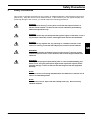
Safety Precautions
This receiver is intended exclusively for the reception of satellite broadcasts, and should be used for that
purpose only. Keep the receiver out of children’s reach. In the interest of your own personal safety and
preventing damage to the receiver, you should observe the following precautions:
DANGER:
Do not open its housing’s cover panel, since that will expose sources of
electric-shock hazards. All work on the receiver should be performed by
authorized specialists only.
DANGER:
Keep the receiver dry and well-protected against ingress of moisture, since if
any moisture enters the receiver, that might create electric-shock hazards.
DANGER:
Do not insert any objects into any openings or ventilation louvres on the
receiver’s housing, since that will subject you to electric-shock hazards.
GB
WARNING:
Make certain that the ventilation louvres on the receiver’s housing remain
unobstructed at all times, since otherwise the receiver might overheat and
catch fire.
WARNING:
Use only factory-original replacement parts or such recommended by your
dealer, since using any other parts might result in personal injuries and/or
property damage. Failure to observe this warning will void the equipment
warranty.
NOTE:
Switch the receiver off during thunderstorms and whenever it remains out of
service for extended periods.
NOTE:
To clean the receiver, wipe it off with a damp cloth only. Do not use any
chemical cleaners.
Version 1.0
Page 5
The Receiver and Its Operation
4
The Receiver and Its Operation
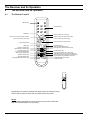
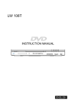
4.1
The Remote Control
ON/OFF-Key
Numerical Keys
MANU-key
Cursor-Control Key (cursor up)
Volume-Control Key (decrease volume)
Cursor-Control Key (cursor left)
Volume-Control Key (increase volume)
Cursor-Control Key (cursor right)
Cursor-Control Key (cursor down)
Light-Emitting Diode
Muting Key
Television Selector Key
Digital-Receiver Selector Key
Channel-Directory Key
(Low-Threshold Setting Key)
Blue-Screen Selector Key
TV/Radio Selector Key
(West-Orientation Key)
Analog/Digital Mode-Selector Key
Programming Key
Video-Recorder Selector Key
External-Analog-Receiver Selector Key
Exit-Menu/Save Key
Last-Channel Selector Key (Tuner A/B)
Audio-Mode Selector Key (channel allocation)
Channel-Information Key (East-Orientation Key)
Program-Guide Key (Satellite-Position Key)
Enables/Disables Scart Output
to Video Recorder
Designations enclosed in parentheses apply to both the analog-receiver
section and the antenna controller (an optional accessory item).
NOTE:
When inserting the batteries into the remote control, make certain that
they are inserted with the correct polarity.
Page 6
Version 1.0
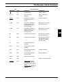
The Receiver and Its Operation
Key
Marking(s)
Color
Function During:
Operation
Installation
red
ON/OFF-switch
ON/OFF-switch
0,1,2,3, ...
gray
Entry of channel
numbers
Entry of parametersettings
MENU
6(/(&7
blue
Menu key for calling up
and exiting onscreen
menus
Channel selection
CHp
blue
Selects the next larger
channel number or the
preceding line of the
onscreen menu
Selects/marks a field of
the onscreen menu
CHq
blue
Selects the next lower
channel number or the
following line of the
onscreen menu
Selects/marks a field of
the onscreen menu
u
blue
Increases sound volume
Selects/marks a field of
the onscreen menu
t
blue
Reduces sound volume
Selects/marks a field of
the onscreen menu or
corrects an incorrect
numerical entry
TV
blue
Selects television-set
operation
VCR
blue
Selects video-recorder
operation
SAT
blue
Selects analog satellitereceiver mode
Channel selection
DVB
blue
Selects digital satellitereceiver mode
Channel selection
MUTE
gray
Mutes the sound track
SET
gray
FAV(LT)
RCL
gray
Version 1.0
GB
Saves a channel selection
Digital mode: Calls up
display of the channel
list (listed in the preferred
order)
Analog mode: Recalls the
low-threshold setting for
resetting
Page 7
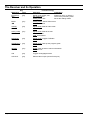
The Receiver and Its Operation
Marking(s)
Page 8
Key
Color
Function During:
Operation
Installation
Deletes an entry or effects a
return to the preceding menu
Saves the settings made
EXIT(STO)
REV
gray
Digital mode: STOP, exit
the current menu
Analog mode: N/A
BACK
tt
gray
Analog mode: Selects blue screen
VCR: Fast rewind
AUD(#)
u
gray
Digital mode: Selects audio mode
VCR: Play
LAST(T A/B)
uu
gray
Digital mode: Selects the last
channel viewed
VCR: Fast forward
RADIO(W)
II
gray
Digital mode: Toggles TV/Radio
VCR: Pause
GUIDE(SAT)
n
gray
Digital mode: Calls up the program guide
VCR: STOP
INFO(E)
l
gray
digital: Calls up further channel information
VCR: Record
A/D
gray
Toggles analog/digital mode
VCR OUT
gray
Selects video output (via the Scart jack)
Version 1.0
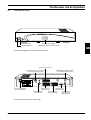
The Receiver and Its Operation
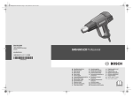
4.2
The Receiver Unit
ON/OFF-Switch
Channel-Selector
Four-Digit LED-Display
(indicates the current channel number)
GB
Controls and displays on the receiver’s front panel
Scart Jack for a TV-Set
Analog-Signal IF-Input Connector
for a Coaxial Antenna Cable
IF INPUT
+13V/+18V
400mA MAX.
WARNING:
IF INPUT
+13V/+18V
400mA MAX.
VIDEO
WARNUNG:
AC95 265V
50Hz MAX30W
Digital-Signal IF-Input Connector
for a Coaxial Antenna Cable
TV
ANALOG
AVERTISSEMENT:
CAUTION
L
RS 232
AUDIO
IF OUTPUT
R
AVIS:
VORSICHT:
DIGITAL
VCR
Line-Cord Receptacle
(95 VAC - 265 VAC)
Scart-Jack for a
Video Recorder
Audio Output to a
Hi-Fi System
DECODER
RS-232 Serial
Interface for a PC
Scart Jack for a
Channel Decoder
IF-Output Jack
for an External
Analog Receiver
Connectors on the receiver’s rear panel
Version 1.0
Page 9
Installing the Receiver
5
Installing the Receiver
5.1
Prerequisites and Ambient Conditions
NOTE:
Keep the receiver well away from sources of heat and locations where it might be
subjected to bright sunlight.
Route all cabling such that it will not become damaged by, e.g., sharp edges.
Connect the receiver to a 230 VAC (± 10%), 50 Hz, electrical outlet.
The antenna assembly should have been installed and aligned in accordance with its manufacturer’s
instructions.
All information needed for programming the receiver’s digital section should be readily available:
− the local time zone (the departure from CET, or GMT in the UK and Ireland),
− whether standard time or daylight-savings time is currently in effect
− the aspect ratio of the television set to be employed
− the LNB local-oscillator frequency that applies to your locality (which must be entered into the field
entitled “LNB Local Freq.”)
− if the receiver is to be manually programmed, the channel frequencies and symbol rates for the
channels to be programmed (available from satellite-television magazines or dealers).
The receiver consists of an analog section (analog receiver) and a digital section (digital receiver).
The analog receiver is ready for immediate use, since it has been preprogrammed at the factory.
However, you may make any changes that may be necessary by following the programming instructions
to be given below.
The digital receiver, on the other hand, must be programmed by users prior to use in accordance with the
instructions to be given below.
5.2
Connecting the Receiver to the Satellite Antenna and Other Equipment
The receiver may be operated with either a single satellite antenna or a pair of satellite antennae. You
will have to manually set the receiver to either single-antenna or dual-antennae mode, depending upon
whether you will be connecting it to one satellite antenna or a pair of satellite antennae using one or two
(coaxial) antenna cables, respectively. To perform this setting, proceed as follows:
NOTE:
Before proceeding, correctly connect the receiver to the video recorder, television
set, any further (analog) receivers to be employed, and then to an electrical outlet.
•
•
•
•
•
Page 10
Press the blue DVB-key on the remote control. The red indicator lamp (LED) on
the remote control will briefly illuminate.
Press the A/D-key on the remote control and hold it depressed for 3 seconds,
which will switch the receiver to standby mode..
Use the t or u keys to select either SING (single-antenna mode) or DUAL
(dual-antennae mode).
Press the ON/OFF key.
If the receiver is to be operated in single-antenna mode, use the coaxial cable
supplied with the receiver to interconnect the “IF OUTPUT DIGITAL“ and “IF
INPUT ANALOG“ jacks on its rear panel (cf. Section 5.2.1, below).
Version 1.0
Installing the Receiver
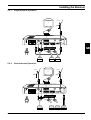
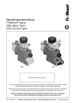
5.2.1
Single-Antenna Operation
Antenna
TV
RF INPUT
+13V/+18V
400mA MAX.
WARNING:
~
WARNUNG:
AC95~265V
50Hz MAX30W
AVERTISSEMENT:
RF INPUT
+13V/+18V
400mA MAX.
VIDEO
TV
ANALOG
L
RS 232
AUDIO
CAUTION
RF OUTPUT
R
AVIS:
VORSICHT:
DIGITAL
VCR
DECODER
GB
Hi-Fi
System
5.2.2
Video
Recorder
Analog
Decoder
Dual-Antennae Operation
Antenna
Antenna
TV
RF INPUT
+13V/+18V
400mA MAX.
WARNING:
~
WARNUNG:
AC95~265V
50Hz MAX30W
AVERTISSEMENT:
RF INPUT
+13V/+18V
400mA MAX.
VIDEO
TV
ANALOG
CAUTION
L
RS 232
AUDIO
RF OUTPUT
R
AVIS:
VORSICHT:
DIGITAL
VCR
Hi-Fi
System
DECODER
Video
Recorder
Analog
Decoder
External
Analog
Receiver
Version 1.0
Page 11
Programming and Operating the Analog-Receiver Section
6
Programming and Operating the Analog-Receiver Section
•
•
Switch the receiver on by pressing the ON/OFF-key.
Press the A/D-key on the remote control in order to switch
from using the receiver’s digital section to using its analog
section.
NOTE:
You may suppress the picture for the current channel and obtain a blue screen by
pressing the BACK-key, if desired. The system menu will be displayed onscreen
even in the absence of an input signal.
•
6.1
You may also suppress the sound track for the current channel
by pressing the MUTE-key, if desired, in which case the message
“SOUND OFF“ will appear onscreen. Pressing the MUTE-key a
second time will restore the sound track.
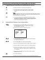
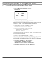
Setting the Basic Parameters from the System Menu
•
Simultaneously press the p and q keys on the receiver’s
front panel while the receiver is in standby mode and hold
them depressed for 3 seconds.
The following menu will then be displayed onscreen:
SYSTEM MENU
LANGUAGE
DRO SHIFT
LNB FREQ.
SMATV
:
:
:
:
ENGLISH
00.00MHZ
9.75GHZ
OFF
•
Use the p and q keys to shift the cursor to the desired position
(the highlighted display line).
•
Use the t and u keys to select the desired setting.
•
Select the desired language (Deutsch, English, Français, Italiano).
•
Select an LNB-local-oscillator frequency of 9.75 GHz/10.00 GHz.
•
•
•
Adjust the local-oscillator frequency in steps of 0.25 MHz until it
agrees with your LNB (the available frequency-adjustment range
is ± 15.00 MHz).
Select “ON” if you intend to use the receiver’s SMATV-feature
(DiSEqC Version 1.0)
Press the STORE-key.
The data have now been saved and the receiver will automatically switch off.
Page 12
Version 1.0
Programming and Operating the Analog-Receiver Section
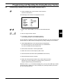
6.2
Preselecting Channels from the Main Menu (Display Page 1)
•
Press the MENU-key on the remote control while the
receiver is switched on.
The following menu will then be displayed onscreen:
MAIN MENU
> CHANNEL
BAND
FREQ.
POLARITY
22KHZ
DECODER
CONTRAST
P. LOCK
•
•
•
:
:
:
:
:
:
:
:
400
KU-09.75GHZ
12150.00MHZ
HORZ.
OFF
NO
5
OFF
Either use the t and u keys to select a channel/broadcaster,
or
GB
enter a 3-digit channel number.
If necessary, reset the local-oscillator frequency
(5.15 GHz/9.75 GHz or 10.00 GHz/10.60 GHz).
If your antenna is capable of receiving C-band broadcasts, you may reconfigure the
receiver setup in order to allow receiving them by using a setting of C-05.15 GHz.
•
Use the t and u keys or the numerical keys to adjust/reset
the channel frequency to the desired value (cf. the addendum
for a list of available channel frequencies).
•
Select either horizontal or vertical polarization.
•
Switch the 22-kHz control frequency ON or OFF.
•
Select the desired decoder status (NONE/MAC/PAL1/PAL2).
•
Select the desired picture contrast.
•
Switch the child-protection feature ON in order that the channel
selection can only be altered by a numerical entry, and can no
longer be altered using the p and q keys.
While the cursor ( > ) is in the bottom display line, you may use the q key to switch
to the next menu. While it is in the top display line, pressing the p key will return
you to the preceding menu.
Version 1.0
Page 13
Programming and Operating the Analog-Receiver Section
6.3
Preselecting Channels from the Main Menu (Display Page 2)
•
Press the q key to exit Display Page1 and call up
Display Page 2.
MAIN MENU
> AUDIO
L
R
DE-EMPH
B/W
L/R DIST.
AUDIO
RADIO
•
:
:
:
:
:
:
:
7.02MHZ
7.20MHZ
STEREO/ADAPT
150KHZ
180KHZ
INTERNAL
OFF
Use the t and u keys or numerical keys to adjust/reset
the left-channel audio-subcarrier frequency.
Before the right-channel audio-subcarrier frequency can be adjusted or reset, L/R
must be set to “FREE.” To make this adjustment, proceed as follows:
•
•
Use the t and u keys or the numerical keys to set the
desired right-channel audio-subcarrier frequency.
Select audio deemphasis and the desired bandwidth:
STEREO/ADAPT – MONO/ADAPT –
MONO/50u – MONO/J17.
If the deemphasis parameters have been set to “MONO,” you may select an audio
bandwidth of 150/280/400/600 kHz.
•
Set the L/R channel separation to “FREE” or 180 kHz.
If this has been set to “FREE,” the bandwidths of the left and right audio channels
may be independently adjusted or reset. If it has been set to 180 kHz, the
bandwidth for the right channel will automatically track that set for the left channel.
•
•
Page 14
Select “AUDIO EXTERNAL” (i.e., via a Scart loop) or
“AUDIO INTERNAL,” which will only be possible if
“DECODER” has been set to a setting other than “NONE.”
Select “RADIO ON” if you would like to have a black screen
while listening to the radio.
Version 1.0
Programming and Operating the Analog-Receiver Section
6.4
Preselecting Channels from the Main Menu (Display Page 3)
The settings of Display Page 3 should be altered by a trained specialist only.
•
Press the q key while the cursor is in the bottom display
line to transit from Display Page 2 to Display Page 3:
MAIN MENU
> TONE BURST : A
SWITCH INPUT : 1
•
•
Version 1.0
Reset DiSEqC to A or B.
Switch the SMATV-feature ON if you want your receiver to
receive DiSEqC-signals, which will only be possible if the
SMATV-feature has been enabled from the system menu.
GB
Page 15
Setting Up and Programming the Digital Receiver
7
Setting Up and Programming the Digital Receiver
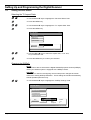
7.1
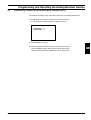
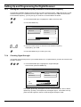
Switching On the Receiver
•
Actuate the ON/OFF switch on the receiver.
The display will indicate “ON” to indicate that the receiver is
on, and the following display page will appear onscreen:
Press MENU key to setup
•
Press the MENU-key on the remote control. The following
menu will then be displayed onscreen:
Main Menu
Language
Time Setting
Installation
Decoder Status
Setup Value
Language
English
Time Offset GMT+00:00
MENU/EXIT
Page 16
Version 1.0
Setting Up and Programming the Digital Receiver
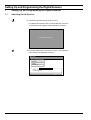
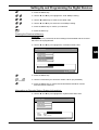
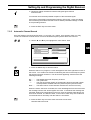
7.2
Language Selection
•
Use the p and q keys to highlight the “Language”
field, as shown below:
Main Menu
1-1
Language
Time Setting
Installation
Decoder Status
Language
English
MENU/EXIT
•
•
•
7.3
Press the MENU-key on the remote control.
Use the CHp and CHq keys to bring the desired choice of language
(Deutsch/English/Français/Italiano) into the field at the bottom of the screen.
Press the MENU-key to confirm your selection or the EXIT-key to
abandon the current selection and make another selection.
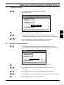
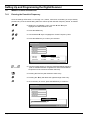
Setting the Correct Local Time
•
Use the CHp and CHq keys (designated by p or q below and in the
other sections to follow) to highlight the “Time Setting” field, as shown below:
Main Menu
1-2
Language
Time Setting
Installation
Decoder Status
Time Setting
Offset
GMT
Summer
OFF
MENU/EXIT
•
Version 1.0
Press the MENU-key to enable altering the value of “OFFSET.”
•
Use the p and q keys to select the offset for your time zone (cf. the
addendum).
•
Use the t and u keys to select “SUMMER” (daylight-savings time).
•
Use the p and q keys to switch “SUMMER” (daylight-savings time) ON/OFF.
•
Press the MENU-key to confirm your selection.
Page 17
GB
Setting Up and Programming the Digital Receiver
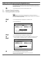
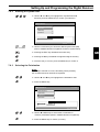
7.4
Setting Decoder Status
Selecting the TV Aspect Ratio:
•
Use the p and q keys to highlight the “Decoder Status” field.
•
Press the MENU-key.
•
Use the p and q keys to highlight the “TV Aspect Ratio” field.
•
Press the MENU-key.
Decoder Status
1-4-1
TV Aspect Ratio
DiSEqC Change
All Channel Clear
System Information
Setup Value
4:3
16 : 9
MENU/EXIT
•
•
Use the t and u keys to select the aspect ratio, 4:3 or 16:9,
for your television set.
Press the MENU-key to confirm your selection.
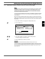
Changing the DiSEqC:
NOTE:
You will not be able to work with the Digital Satellite Equipment Control (DiSEqC)
unless your satellite system is equipped with a DiSEqC-switch.
CAUTION:
This feature is used for reconfiguring receiver setup when changes have been
made to an existing DiSEqC-distributor. These settings should thus be altered by
trained specialist personnel only.
•
Use the p and q keys to highlight the “DiSEqC Change” field.
Decoder Status
1-4-2
TV Aspect Ratio
DiSEqC Change
All Channel Clear
System Information
Setup Value
OLD
NEW
1
1
LNB Polar
Vertical
Band
Low
Sat System
A
MENU/EXIT
Page 18
Version 1.0
Setting Up and Programming the Digital Receiver
•
Press the MENU-key.
•
Use the p and q keys to highlight the “OLD” DiSEqC-setting.
•
Use the t and u keys to transit to the “NEW” field.
•
Use the p and q keys to select the new DiSEqC-setting.
•
Press the MENU-key to confirm your selection.
•
Press the EXIT-key.
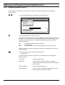
Clearing the Receiver’s Memory:
CAUTION:
If this procedure is performed, all saved settings will be deleted and the receiver
will have to be reprogrammed.
•
Use the p and q keys to highlight the “All Channel Clear” field.
Decoder Status
1-4-3
GB
TV Aspect Ratio
DiSEqC Change
All Channel Clear
System Information
Setup Value
Input password
MENU/EXIT
•
Press the MENU-key.
•
Use the numerical keys to enter the number “9815” (the password).
•
Press the MENU-key to confirm that all stored data should be cleared
from the receiver’s memory.
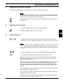
Information on Decoder Status (System Information):
•
Use the p and q keys to highlight the “System Information“ field.
Decoder Status
1-4-4
TV Aspect Ratio
DiSEqC Change
All Channel Clear
System Information
Setup Value
Data
: 20.07.98
Revision
: ME 1.0
Firmware
: 2.08A / 0.12 / 0.30
MENU/EXIT
Version 1.0
Page 19
Setting Up and Programming the Digital Receiver
The displayed data concerns the revision of the decoder firmware current at the
time the receiver was manufactured, which might be of value if the receiver should
ever require servicing.
•
Press the EXIT-key to exit the “Decoder Status“ menu.
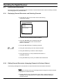
7.5
Automatic Channel Preselection
7.5.1
Selecting the Satellite to be Used
NOTE:
Four satellites have been factory preprogrammed. Contact your dealer or a
television repair shop specializing in satellite-television systems if you would like to
have further satellites programmed.
•
Use the p and q keys to highlight the “Installation“ field.
•
Press the MENU-key.
Installation
1-3
Satellit
Signal Stärke
DiSEqC/22KHz
Autom. Suchlauf
LNB Lokal-Freq
Manueller Suchlauf
Einstellungen
Satellit
ASTRA
LNB Lokal 10600MHz
DiSEqC
AUS
22KHz
EIN
MENU/EXIT
•
Use the p and q keys to highlight the “Satellite“ field.
•
Press the MENU-key and then use the p and q keys to select one of the
following satellites: ASTRA/EUTELSAT 13°/ASIASAT2/PANAMASAT2.
Installation
1-3-1
Satellite
Signal Strength
DiSEqC/22KHz
Auto Search
LNB Lokal-Freq
Manual Dearch
Setup Value
ASIASAT2
MENU/EXIT
•
Press the MENU-key to confirm your choice.
You may now preselect the desired channels for the particular
satellite that you have selected.
Page 20
Version 1.0
Setting Up and Programming the Digital Receiver
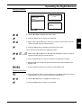
7.5.2
Adjusting the DiSEqC-Controller and/or the 22-kHz Control Signal
NOTE:
This adjustment is used for selecting the correct segment of the frequency bands.
The DiSEqC-controller, which may be used only if the satellite system in use is
equipped with a DiSEqC-switch, incorporates the correct settings for all of the
various parameters involved: upper/lower band, horizontal/vertical polarization,
and the type of satellite system involved.
In the event that the satellite system involved is not DiSEqC-controlled, the setting
for “Upper/Lower Band” will have to be manually entered by toggling the “22kHz“
setting ON/OFF.
Most commercially available satellite systems employ so-called “general-purpose”
LNB’s where a setting of “22 kHz ON” will automatically effect a switch to the upper
band, where all digital satellite channels will be found (the factory default setting is
22 kHz ON).
•
Use the p and q keys to highlight the “DiSEqC/22kHz“ field.
•
Press the MENU-key:
GB
Installation
1-3-2
Satellite
Signal Strength
DiSEqC/22KHz
Auto Search
LNB Lokal-Freq
Manual Search
Setup Value
22KHz
OFF
MENU/EXIT
•
•
Use the p and q keys to toggle the “22kHz“ setting ON/OFF
or select the DiSEqC-controller required.
Press the MENU-key to confirm your choice.
CAUTION:
These settings should be altered by specially trained personnel only.
In order to be able to receive the greatest possible number of channels, you will
have to repeat the automatic-search procedures (cf. Section 7.5.5, below) for each
and every available DiSEqC-setting and for both settings of the 22-kHz control
signal {ON/OFF).
Version 1.0
Page 21
Setting Up and Programming the Digital Receiver
7.5.3
Entering the Low-Noise Block (LNB) Converter’s Local-Oscillator Frequency
Commercially available satellite systems employ so-called “general-purpose” LNB’s that employ a localoscillator frequency of 10,600 MHz for their upper band. In the event that your LNB uses some other
local-oscillator frequency, you may set up your receiver to accommodate it as follows:
•
Use the p and q keys to highlight the “LNB Local Freq“ field:
•
Press the MENU-key.
Installation
1-3-3
Satellite
Signal Stength
DiSEqC/22KHz
Auto Search
LNB Lokal-Freq
Manual Search
Setup Value
5150
MHz
MENU/EXIT
•
•
7.5.4
Use the numerical keys to enter the local-oscillator frequency
employed by your LNB.
Press the MENU-key to confirm your entry.
Checking Signal Strength
You should check the alignment of your satellite antenna on a regular basis if you want to have the bestpossible reception.
•
Use the p and q keys to highlight the “Signal Strength”
field and then press the MENU-key.
Installation
1-3-4
Satellite
Signal Strength
DiSEqC/22KHz
Auto Search
LNB Lokal-Freq
Manual Search
Setup Value
SNR
[STATUS]
EXIT
The legend “[STATUS]” will appear onscreen for a few seconds, when it will be
replaced by “[LOCK],” accompanied by a triangular figure. If the latter has only
yellow and red segments, then the received signal strength is weak.
Page 22
Version 1.0
Setting Up and Programming the Digital Receiver
•
Cautiously realign the antenna until the triangular figure reaches
maximum size.
You will then have the best-possible reception of the broadcast signal.
If the legend “[UNLOCK]” should appear following “[STATUS],” check the cabling
interconnecting the antenna and the receiver and the parameter settings covered
in the preceding sections.
•
7.5.5
Press the EXIT-key to exit this menu.
Automatic Channel Search
Once the settings covered under Sections 7.5.1 through 7.5.4, above, have all been made, you may
conduct an automatic channel search over those downlink frequency bands that have been set.
•
Use the p and q keys to highlight the “Auto Search“ field:
Installation
1-3-5
Satellite
Signal Strength
DiSEqC/22KHz
Auto Search
LNB Lokal-Freq
Manual Search
GB
Setup Value
Search complete
DF:3734 SR:5.832 3/26 New:5
EXIT
•
Press the MENU-key to start the search.
While the search is in progress, a clock will appear at the lower right-hand corner of
the screen. You will also see a blue bar indicating the extent of the frequency band
that has thus far been searched. The other items appearing onscreen have the
following meanings:
DF: .... SR:.... .../...
New:... -
The satellite down-link frequency involved
The symbol rate
The ratio of the total number of transponders found to the total number
of transponders available within the preset frequency band involved
The total number of new channels saved to the receiver’s memory
When the search has been concluded, the clock will disappear from the screen and
the message “Search OK“ should appear onscreen. If instead of this message the
message “Search fail” should appear onscreen, then the settings made above will
have to be checked, one after the other, in the order in which they were made and
corrected wherever necessary until the search is successful.
•
Version 1.0
Press the EXIT-key to exit this menu and view a list of those
channels that were found.
Page 23
Setting Up and Programming the Digital Receiver
7.6
Manual Channel Preselection
7.6.1
Entering the Downlink Frequency
Once the settings of Sections 7.5.1 through 7.5.4, above, have been concluded, you may manually
preselect any of the channels falling within the various preset downlink frequency bands, as follows:
•
While in the “Installation“ menu, use the p and q keys to
highlight the “Manual Search” field.
•
Press the MENU-key.
•
Use the p and q keys to highlight the “Down Frequency” field:
•
Press the MENU-key to confirm your selection.
Manual Search
1-3-6
Down Frequency
Symbol Rate
LNB Polarity
Start Search
Setup Value
LNB Local
5150MHz
DiSEqC
Down Freq
3700MHz
LNB Polar Horizontal
Symbol Rate
28.100MHz
22KHz
4
ON
MENU/EXIT
•
Use the numerical keys to enter the desired downlink frequency
(refer to satellite-television magazines for lists of the downlink
frequencies of the various broadcast channels).
•
Pressing the EXIT-key will delete the entire entry.
•
Pressing the t key will delete the rightmost digit of the entry.
•
Once the entry is correct, press the MENU-key to confirm it.
Manual Search
1-3-6-1
DownFrequency
Symbol Rate
LNB Polarity
Start Search
Setup Value
3700
MHz
MENU/EXIT
Page 24
Version 1.0
Setting Up and Programming the Digital Receiver
7.6.2
Entering the Symbol Rate
•
Use the p and q keys to highlight the “Symbol Rate“ field
and then press the MENU-key to confirm your selection.
Manual Search
1-3-6-2
Down Frequency
Symbol Rate
LNB Polarity
Start Search
Setup Value
28.100
MHz
MENU/EXIT
•
7.6.3
Use the numerical keys to enter the desired symbol rate (SR)
(refer to satellite-television magazines for lists of symbol rates).
•
Pressing the EXIT-key will delete the entire entry.
•
Pressing the t key will delete the rightmost digit of the entry.
•
Once the entry is correct, press the MENU-key to confirm it.
GB
Selecting the Polarization
NOTE:
If a DiSEqC-controller is in use, this setting will be preset by
the controller and thus need not be repeated.
•
Use the p and q keys to highlight the “Polarization“ field.
•
Press the MENU-key.
Manual Search
1-3-6-3
Down Frequency
Symbol Rate
LNB Polarity
Start Search
Setup Value
Horizontal
Vertical
MENU/EXIT
•
•
Version 1.0
Use the t and u keys to select either “Horizontal“ or
“Vertical" polarization (listed in satellite-television magazines).
Press the MENU-key to confirm your entry.
Page 25
Setting Up and Programming the Digital Receiver
7.6.4
Conducting a Manual Search
Once the settings of Sections 7.6.1 through 7.6.3, above, have been concluded, you may initiate a
manual search.
•
Use the p and q keys to highlight the “Start Search“ field.
Manual Search
1-3-6-4
Down Frequency
Symbol Rate
LNB Polarity
Start Search
Setup Value
Search OK
DF:4000 SR:28.125 New:18
EXIT
•
Press the MENU-key to start the search.
While the search is in progress, a clock will appear at the lower right-hand corner of
the screen. You will also see a blue bar indicating the extent of the frequency band
that has thus far been searched. The other items appearing onscreen have the
following meanings:
DF: .... SR:.... New:... -
The satellite downlink frequency involved
The symbol rate
The total number of new channels saved to the receiver’s memory
Once the search has been successfully concluded, the message “Search OK“ will
appear onscreen.
•
Press the EXIT-key to exit the menu and view the
channel found.
If the search fails to locate a channel, one of the following error messages will
appear onscreen:
Page 26
“Tuning fail“
-
Check the symbol rate.
“Search fail“
-
Check the local-oscillator frequency, the signal
strength, the 22-kHz setting, and the choice of satellite
to be involved.
“No free channel“
-
Check the downlink frequency.
“Search cancel“
-
The search was cancelled by pressing the EXIT-key
before the search could be concluded.
Version 1.0
Operating the Digital Receiver
8
Operating the Digital Receiver
Once all of the above settings have been made, your receiver will be ready for use.
NOTE:
Digital television broadcasting involves the transmission and processing of large
quantities of data. Switching from one channel to another thus takes a bit longer
than in the case of analog television broadcasting.
An hourglass or the text message “Please wait” will appear onscreen during this
waiting period.
8.1
Switching On the Receiver
•
Press the ON/OFF-switch on the receiver’s front panel.
•
Press the ON/OFF-key on the remote control.
GB
8.2
Channel Selection
•
Use the numerical keys to enter the number of the desired channel (cf. also
Section 8.3.1, below, regarding procedures for selecting channels from a list).
NOTE:
Although channel numbers invariably have 3 digits, e.g., 001, those with only one
or two significant digits may be entered as single-digit or dual-digit numbers, e.g., 1
or 13. The receiver will have tuned in the selected channel after a delay of about
3 seconds.
•
Use the p or q keys to select the next or preceding channel, respectively.
•
Pressing the LAST-key will return you to the last channel viewed.
Each time you change the channel, the new channel number, date, day of the
week, time of day, and the message “New channel change” will be displayed
onscreen for a few seconds.
If the new channel’s downlink frequency is the same as that of the current channel,
the new channel will be tuned in and the associated data displayed onscreen.
However, if its downlink frequency differs from that of the current channel, the
message “RF signal tuning” will appear onscreen while the new channel is being
tuned in.
If the message “No signal“ appears in this menu, then the channel chosen cannot
be received by your satellite antenna.
These onscreen messages will be deleted after about 3 seconds have elapsed or
whenever the EXIT-key is pressed
This menu displays the channel number and channel-tuning data, along with the
current date, day of the week, and time of day.
Version 1.0
Page 27
Operating the Digital Receiver
8.3
Using Channel Directories
Due to the large number of digital television channels, channel directories are used for selecting channels
and arranging them in preferred orders.
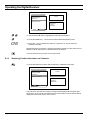
8.3.1
Displaying Channel Directories and Selecting Channels
•
Press the FAV-key on the remote control while viewing
a television program:
Favorite Video
P001 GDTV
P002 Hunan SRTV
P003 DW-tv
P004 MCM
P005 RAI internation
FAV/RADIO/INFO/MENU
You will then have the following facilities available:
•
Using the 9 and : keys to browse through the
pages of the directories, each of which lists a
total of 10 channels.
•
Using the 5 and 6 keys for selecting channels.
•
Using the numerical keys to enter channel numbers.
•
Using the RADIO-key to switch to radio reception.
•
•
8.3.2
Using the INFO-key to call up additional information on
broadcast channels.
Using the MENU-key to save your edited channel directories.
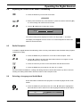
Editing Channel Directories (Arranging Channels in Preferred Orders)
The following data appear in both television-channel directories and radio-station directories.
NOTE:
The channel currently running in the background will change if its channel number
is highlighted for several seconds.
•
Page 28
Pressing the FAV-key (“Favorite Menu” key) while a channel directory is
displayed onscreen will allow you to create or edit a directory listing your
favorite channels.
Version 1.0
Operating the Digital Receiver
Moving Channels:
Favorite Video – Edit
P001 GDTV
TV (PIG)
P002 Hunan SRTV
P003 DW-tv
P004 MCM
Information
P005 RAI internation
Networkname
Frequency
Symbol Rate
MOVE
DELETE
•
Use the t and u to highlight the “Move” field.
•
Press the MENU-key to confirm your selection.
•
•
Either use the p and q keys to select the channel to be moved or enter its
channel number using the numerical keys.
Press the MENU-key to highlight the channel to be moved.
The channel involved will then be displayed in blue.
•
•
•
•
Either use the p and q keys to the select its destination location or enter its
channel number using the numerical keys.
Press the MENU-key to move the channel to the destination location.
Repeat the above procedures until all channels have been arranged in the
desired order.
Press the EXIT-key twice in succession to exit editing mode.
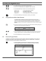
Deleting Channels:
•
Version 1.0
Press the FAV-key while a channel directory is displayed onscreen in order to
enable deletion of one or more channels from that directory.
•
Use the t and u keys to highlight the “Delete” field.
•
Press the MENU-key to confirm your selection.
Page 29
GB
Operating the Digital Receiver
Favorite Video – Edit
P001 GDTV
TV (PIG)
P002 Hunan SRTV
P003 DW-tv
P004 MCM
Information
P005 RAI internation
Networkname
Frequency
Symbol Rate
MOVE
DELETE
•
Use the p and q keys to highlight the channel to be deleted.
•
Press the MENU-key. The channel involved will be displayed in blue.
•
Press the “1“-key to delete the channel, or press the “0”-key to abort the
deletion procedure.
Repeat the above procedures, commencing with the selection of the channel to be
deleted, until all channels to be deleted have been deleted..
•
8.3.3
Press the EXIT-key to return to the “Edit” menu.
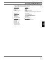
Obtaining Further Information on Channels
•
Press the INFO-key while a channel directory is displayed onscreen.
Favorite Video – Edit
P001 GDTV
TV (PIG)
P002 Hunan SRTV
P003 DW-tv
P004 MCM
Information
P005 RAI internation
Networkname
Frequency
Symbol Rate
MOVE
DELETE
The picture for the channel currently running will be displayed at the upper righthand corner of the screen and further technical information on that channel will be
displayed in the lower section of the screen.
Page 30
Version 1.0
Operating the Digital Receiver
8.4
Adjusting the Volume of the Sound Track/Muting
•
Press the MUTE-key to mute the sound track.
MUTE
•
•
Either press the MUTE-key a second time or press the volume-control key (u)
to cancel muting and restore the sound track.
Use the t and u keys to adjust the volume.
VOL. 15
The volume setting will be displayed in terms of a range (MIN, 1 - 30, MAX).
The display will disappear from the screen if no volume adjustments have been
made for several seconds.
8.5
Radio Reception
In addition to digital television broadcasting, there are many radio stations that broadcast radio programs
in digital Hi-Fi quality.
•
•
Press the RADIO-key to switch from TV-mode to radio-reception mode.
Use the p or q keys to select the radio station with the next higher or lower
broadcast frequency, respectively.
•
Press the LAST-key to return to the radio station that was last tuned in.
•
Press the RADIO-key a second time to return to TV-mode.
All of the facilities available for creating and editing television-channel directories may also be used for
creating and editing radio-station directories while in radio-reception mode.
8.6
Selecting a Language and Audio Mode
Some radio station broadcast radio programs in several languages and/or audio
modes.
•
Press the AUDIO-key and then press one of the t or u keys to highlight the
left-hand field in order to select one of the languages broadcast by the station.
Audio Mode
BL 1:
Version 1.0
Stereo (L+R)
Page 31
GB
Operating the Digital Receiver
•
•
Use p and q keys to select the language desired.
•
Use the p and q keys to select one of the following options:
Press one of the t or u keys to highlight the right-hand field.
Stereo (L+R)
Mono1 (L+L)
Mono2 (R+R)
Swap (R+L)
•
8.7
–
–
–
–
Left and right stereo channels
Left stereo channel only
Right stereo channel only
Left and right stereo channel interchanged
Press the AUDIO-key a second time to confirm your selection.
Using the Receiver With a Video Recorder
This feature will be needed if you intend to operate the receiver in dualantennae mode and record television programs on a video cassette recorder
(VCR). The VCR-output jack will then transmit information on whether the
television program to be recorded is coming from the receiver’s analog or digital
section.
•
Press the VCR OUT-key to access the menu items used or selecting the type of
signal to be sent to the VCR Scart-output jack.
VCR-SCART output
Analog
Digital
•
•
8.8
Use the t and u to select the type of signal (output signal from the receiver’s
analog or digital section) to be made available at the VCR-Scart output jack.
Press the MENU-key to confirm your selection.
Onscreen Program Guides
In addition to broadcasting digital video and audio signals, television broadcasters have the option of
transmitting information on their programming schedules in the form of a data stream. Pressing the
GUIDE-key will call up this information for display onscreen.
•
Press the GUIDE-key while watching a television program to call up the
following display page (this facility is unavailable during radio reception):
Program Guide – Video
Data
: 21/2/1998
Video
:
End time
: 10:30
Audio
:
Content
:
EBU data
:
Rating
:
Story
:
Press EXIT to stop search
Page 32
Version 1.0
Operating the Digital Receiver
This information largely consists of programming schedules, along with additional
information provided by broadcasters, such as:
Version 1.0
Video Format:
4:3
16:9
16:9 (pan vector)
> 16:9
Content:
Movies/drama
News
Shows/game shows
Sports
Children’s programs/programs for young people
Audio Mode:
Single mono
Dual mono
Stereo
Multilingual
Surround sound
Music/dance
Art/cultural programs
Social matters/politics/business
Educational programs/science
Recreation
Special topics
EBU-Data:
Teletext subtitles
Teletext
Subtitles
Subtitles (4:3)
Subtitles (16:9)
Subtitles (2.21:1)
Approved for:
Children over 7 years old
GB
Page 33
Programming the Remote Control
9
Programming the Remote Control
The remote control may be programmed using two different methods, either by entering a three-digit
manufacturer’s code (manufacturer’s ID) taken from the addendum or by means of a systematic search.
Method 1: Entering the Manufacturer’s Code:
Step 1:
Press the SET-Taste and hold it depressed for about 3 seconds until
the red LED illuminates.
Step 2:
Press the key for the type of device to be controlled:
SAT
DVB
TV
VCR
Step 3:
Analog satellite receivers
Digital satellite receivers
Television sets
Video cassette recorders
Look up the manufacturer’s code for the particular model to be
controlled in the addendum, which will be listed under the
manufacturer’s name. If more than one code is listed, try out each of
them in turn.
Switch on the device to be controlled.
Point the remote control at that device.
Enter (one of) its three-digit manufacturer’s code(s) using the numerical
keys. The device will switch off if the code entered is the correct one.
Step 4:
Press the SET-key to save the entry. The red LED will blink three times
and then be extinguished.
If nothing happens, repeat Steps 1 through 4 using another choice of
manufacturer’s code.
Method 2: Systematic Search:
Step 1:
As for Method 1.
Step 2:
As for Method 1.
Step 3:
Switch on the device to be controlled.
Point the remote control at that device.
Repeatedly press the red ON/OFF-key and continue repeatedly
pressing it until the device switches off.
NOTE:
Many devices are rather slow to switch off. You should thus wait a few seconds to
see if the device switches off between presses of the ON/OFF-key.
Page 34
Version 1.0
Troubleshooting Tips
Step 4:
Press the SET-key to save the setting. The red LED will
blink three times and then be extinguished.
If nothing happens, repeat Steps 1 through 4.
When programming of the remote control has been concluded:
•
•
10
The red LED will briefly illuminate. You may then use the remote control for
controlling the device, as specified in the table of Section 4.1, above, for the
particular type of device involved.
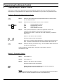
Troubleshooting Tips
Problem
Possible Cause(s)
Suggested Remedies
Remote control
inoperative.
The batteries are discharged.
Replace the batteries.
The wrong blue key was
pressed.
The remote control is not
pointed at the device to be
controlled.
The satellite system is
defective, the antenna is
misaligned, or the LNB is
defective.
The antenna is misaligned.
Press the blue key for the particular type
of device involved.
Point the remote control at the device
involved.
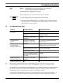
No picture, but the
onscreen menu is
present.
White/black snow on
several channels
(analog reception only).
Snow still present
following fine tuning
(analog reception only).
Audio interference
(analog reception only)
11
Press the blue key for the type of device to be controlled.
High signal attenuation on the
cable connecting the receiver
to the satellite antenna.
The LNB is defective.
Bad contacts at one or more
connectors (water has gotten
into them or their contacts are
corroded).
The satellite antenna employed
is too small or the LNB is
defective.
Audio frequency incorrectly
set.
Check the satellite-antenna cable and
all connectors. Realign the antenna.
Check the LNB.
Realign the antenna. Fine tune the
receiver-LNB from the System menu.
Replace the satellite-antenna cable
or use a signal amplifier.
Replace the LNB.
Repair or replace the connector(s)
involved.
Replace the antenna with a larger one.
Replace the LNB.
Set the correct audio frequency.
Disposing of the Receiver, Its Packagings, and Accessory Items
The satellite receiver, its packagings, and its batteries are not household waste and must be disposed of
separately. Inquire with your local authorities regarding applicable regulations and proper disposal
procedures and, if you must dispose of them, do so in accordance therewith.
You should save all packagings for later use in the event that the receiver must be transported, e.g., if
you move house, or sent in for repair, since only they provide the necessary degrees of protection.
Version 1.0
Page 35