1
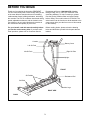
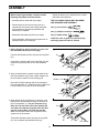
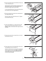
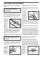
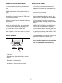
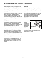
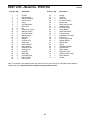
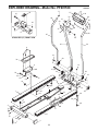
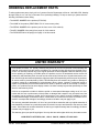
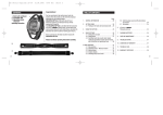
™
Model No. PF601530
Serial No.
Write the serial number in the space
above for reference.
Serial
Number
Decal
QUESTIONS?
As a manufacturer, we are committed to providing complete
customer satisfaction. If you
have questions, or find that there
are missing or damaged parts,
we will guarantee you complete
satisfaction through direct assistance from our factory.
TO AVOID UNNECESSARY
DELAYS, PLEASE CALL DIRECT
TO OUR TOLL-FREE CUSTOMER
HOT LINE. The trained technicians on our customer hot line
will provide immediate assistance, free of charge to you.
CUSTOMER HOT LINE:
1-800-999-3756
Mon.–Fri., 6 a.m.–6 p.m. MST
CAUTION
Read all precautions and instructions in this manual before
using this equipment. Save this
manual for future reference.
USER'S MANUAL
TABLE OF CONTENTS
IMPORTANT PRECAUTIONS . . . . . . . . . . . . . . . . . . . . . . . . . . . . . . . . . . . . . . . . . . . . . . . . . . . . . . . . . . . . .2
BEFORE YOU BEGIN . . . . . . . . . . . . . . . . . . . . . . . . . . . . . . . . . . . . . . . . . . . . . . . . . . . . . . . . . . . . . . . . . .3
ASSEMBLY . . . . . . . . . . . . . . . . . . . . . . . . . . . . . . . . . . . . . . . . . . . . . . . . . . . . . . . . . . . . . . . . . . . . . . . . . . .4
ADJUSTMENT AND OPERATION . . . . . . . . . . . . . . . . . . . . . . . . . . . . . . . . . . . . . . . . . . . . . . . . . . . . . . . . . .6
MAINTENANCE AND TROUBLE-SHOOTING . . . . . . . . . . . . . . . . . . . . . . . . . . . . . . . . . . . . . . . . . . . . . . . . .8
CONDITIONING GUIDELINES . . . . . . . . . . . . . . . . . . . . . . . . . . . . . . . . . . . . . . . . . . . . . . . . . . . . . . . . . . . .9
PART LIST . . . . . . . . . . . . . . . . . . . . . . . . . . . . . . . . . . . . . . . . . . . . . . . . . . . . . . . . . . . . . . . . . . . . . . . . . .10
EXPLODED DRAWING . . . . . . . . . . . . . . . . . . . . . . . . . . . . . . . . . . . . . . . . . . . . . . . . . . . . . . . . . . . . . . . . .11
ORDERING REPLACEMENT PARTS . . . . . . . . . . . . . . . . . . . . . . . . . . . . . . . . . . . . . . . . . . . . . . .Back Cover
LIMITED WARRANTY . . . . . . . . . . . . . . . . . . . . . . . . . . . . . . . . . . . . . . . . . . . . . . . . . . . . . . . . . .Back Cover
IMPORTANT PRECAUTIONS
WARNING: To reduce the risk of serious injury, read all precautions and instructions in this manual
before using the cross-country skier.
1. Read all instructions in this manual and in
the accompanying literature before using
the cross-country skier.
6. The cross-country skier should not be used
by persons weighing more than 200 pounds.
7. Always wear proper clothing and athletic
shoes when using the cross-country skier.
2. It is the responsibility of the owner to
ensure that all users of the cross-country
skier are adequately informed of all precautions.
8. Keep hands and feet away from moving
parts.
3. Place the cross-country skier on a level surface. Cover the floor under the cross-country skier to protect it.
9. Always dismount the cross-country skier
before changing the tension of the ski pedal
strap or the resistance of the ski poles.
4. Inspect and tighten all parts regularly.
Replace any worn parts immediately.
10. If you feel pain or dizziness at any time
while exercising, stop immediately and
begin cooling down.
5. Keep small children and pets away from the
cross-country skier at all times.
11. Use the cross-country skier only as
described in this manual.
WARNING: Before beginning this or any exercise program, consult your physician. This is especially important for persons over the age of 35 or persons with pre-existing health problems. Read all
instructions before using this product. ICON assumes no responsibility for personal injury or property damage sustained by or through the use of this product.
SAVE THESE INSTRUCTIONS
2
BEFORE YOU BEGIN
Thank you for selecting the innovative PROFORM®
570 XC cross-country skier. Cross-country skiing is one
of the most effective exercises known for increasing
cardiovascular fitness, building endurance, and toning
the muscles. The 570 XC combines ultra-smooth skiing
pedals, adjustable resistance, and an electronic exercise monitor to let you enjoy this dynamic exercise in
the convenience and privacy of your home.
Department toll-free at 1-800-999-3756, Monday
through Friday, 6 a.m. until 6 p.m. Mountain Time
(excluding holidays). To help us assist you, please
note the product model number and serial number
before calling. The model number is PF601530. The
serial number can be found on a decal attached to the
cross-country skier (see the front cover of this manual
for the location).
For your benefit, read this manual carefully before
you use the cross-country skier. If you have additional questions, please call our Customer Service
Before reading further, please review the drawing
below and familiarize yourself with the parts that are
labeled.
Console
Battery Cover
Left Ski Pole
Left Ski Pole
Right Ski Pole
Upright
FRONT
Ski Pedals
Resistance Dial
Ski Rails
Incline Legs
RIGHT SIDE
BACK
3
ASSEMBLY
Before beginning assembly, carefully read the
following information and instructions:
• Tighten all parts as you assemble them, unless
instructed to do otherwise.
• Assembly will be easier with two people.
THE FOLLOWING TOOLS (NOT INCLUDED)
ARE REQUIRED FOR ASSEMBLY:
• Place all parts of the cross-country skier in a
cleared area and remove the packing materials;
do not dispose of the packing materials until
assembly is completed.
One (1) pair of pliers
One (1) phillips screwdriver
• Read each assembly step before you begin.
One (1) rubber mallet
• During assembly, make sure that all parts are oriented as shown in the drawings.
Lubricant, such as grease or petroleum jelly,
and soapy water will also be needed.
1. Before beginning, make sure that you have read
the information at the top of this page.
1
Unscrew the Resistance Dial (19) from the Long Bolt
(21).
19
Using pliers, grip the head of the Long Bolt (21) and
remove it from the bracket on the Front Stabilizer
(17).
21
17
2. Apply a small amount of grease to both sides of the
two Nylon Washers (18). Press a Nylon Washer into
the outer side of each Ski Pole Housing (29).
2
24
25
Grease—18
Place the Ski Pole Housings (29) in the bracket on
the Front Stabilizer (17). Make sure that the Right and
Left Ski Poles (24, 25) are on the correct sides.
18—Grease
29
17
3. Apply grease to the Long Bolt (21). Insert the Long
Bolt from the indicated side through the bracket on
the Front Stabilizer (17). As you insert the Long
Bolt, look into the lower end of the Upright (26)
and make sure that the Long Bolt does not damage the Console Wire (15) inside the Upright.
Make sure that the head of the Long Bolt is in the
square hole in the bracket.
3
19
Square
Hole
26
Thread the Resistance Dial (19) onto the Long Bolt
(21). Do not tighten the Resistance Dial yet.
15
4
17
21—Grease
4. Remove the paper backing from Adhesive Strips (32)
on the Housing Cap (20).
4
32
Align the notch in the lower edge of the Housing Cap
(20) with the bracket on the Front Stabilizer (17).
Press the Housing Cap onto the bracket.
42
Lift the Upright Bracket (40). Place the Spring (42) on
the metal tab under the Upright Bracket.
20
40
5. Raise the Upright (26) until the lower end snaps into
the Upright Bracket (40).
5
17
24
26
Raise the Right and Left Ski Poles (24, 25). Tighten
the Resistance Dial (19).
19
25
40
6. Lift the Front Stabilizer (17). Insert the Incline Legs
(38) up into the holes near the ends of the Front
Stabilizer. Make sure that the Incline Legs are turned
as shown.
6
17
38
7. Plug the lower end of the Console Wire (15) into the
Reed Switch Wire (35).
7
15
8. Plug the upper end of the Console Wire (15) into the
wire extending from the Console (27).
8
Attach the Console (27) to the top of the Upright (26)
with four Console Screws (36). Make sure that the
Console Wire (15) is not pinched between the
Console and the Upright.
35
27
Wire
15
26
36
5
ADJUSTMENT AND OPERATION
ADJUSTING THE TENSION OF THE SKI PEDAL
STRAP
CHANGING THE INCLINE OF THE SKI RAILS
Another way to tailor the intensity of your exercise is
to change the incline of the ski rails. There are three
incline levels.
CAUTION: Always dismount the crosscountry skier before changing the tension of
the ski pedal strap.
For a high or
Medium
medium incline
Low
level, first tip
the cross-counHigh
try skier onto
its side. Insert
the incline legs
into the bottom
of the front stabilizer. The
incline level will
differ depending on which ends of the incline legs are
inserted. Set the cross-country skier upright. For a low
incline level, insert the incline legs into the top of the
front stabilizer, with the front stabilizer resting on the
floor.
Before using the cross-country skier, the tension of
the ski pedal strap should be adjusted. If the tension
is too low, the ski pedal strap may slip off the pulleys.
If the tension is too high, the strap and other parts
may wear excessively.
To adjust the
Ski
tension of the
Pedal
ski pedal strap,
Strap
first remove
Metal
the strap knob
Brackets
from the ski
pedal. Next,
slide off the
Strap
two metal
Knob
brackets. To
tighten the
strap, overlap
the metal brackets so that the ends of the strap are
closer together. Slide the metal brackets back onto
the ski pedal. Tighten the strap knob onto the ski
pedal, making sure that the metal brackets remain
parallel to each other as you tighten the knob.
EXERCISING ON THE CROSS-COUNTRY SKIER
Hold both ski poles firmly. Step onto the ski pedals
and center your feet on the pedals. The correct form
for using the cross-country skier is similar to the
motion of walking. Move your arms and legs forward
and backward with a smooth motion. Keep your back
straight and your knees bent slightly. For effective aerobic exercise, short, rapid strides at low resistance
are recommended. To strengthen the muscles, long,
slow strides at medium resistance are recommended.
CHANGING THE RESISTANCE OF THE SKI POLES
For a lower-body workout, hold the handle on the
upright and exercise using only your legs.
CAUTION: Always dismount the cross-country skier before changing the resistance of
the ski poles.
INSTALLING BATTERIES IN THE CONSOLE
The console requires two "AA" batteries (not
included); alkaline batteries are recommended. Slide
off the battery cover as shown below and carefully
remove the battery clip. Find the markings inside the
battery clip showing which direction the batteries must
be turned.
Press two
Battery
"AA" batteries
Console
Clip
into the battery clip.
Insert the battery clip into
Battery
the console
Cover
and slide on
the battery
cover.
The intensity of your exercise can be varied by changing the resistance of the ski poles. The resistance is
controlled with the resistance dial at the lower end of
the right ski pole.
To increase the
resistance of
the ski poles,
turn the resistance dial
clockwise; to
decrease the
resistance, turn
the dial counterclockwise.
Resistance
Dial
6
DESCRIPTION OF THE CONSOLE MODES
OPERATING THE CONSOLE
The console features five modes to provide continuous exercise feedback. The five modes are described
below.
1. To turn on the power, press the on/off button or
simply begin exercising. The entire display will
appear for two seconds. The monitor will then be
ready for operation.
SPEED—Displays your current speed, in strides per
minute.
2. Select one of the five modes:
SCAN mode—When the power is turned on, the
SCAN mode will automatically be selected. One
mode indicator will appear by the word SCAN, and
a second mode indicator will show which mode is
currently displayed. Note: The SCAN mode can
also be selected by repeatedly pressing the mode
button.
TIME—Displays the elapsed time. Note: If you stop
exercising for ten seconds or longer, the TIME mode
will pause until you resume.
DISTANCE—Displays the total number of strides you
have completed.
CALORIES—Displays the approximate number of
Calories you have burned. Note: The actual number
of Calories you have burned may vary slightly from
the number displayed, depending on the resistance of
the ski poles and the incline of the ski rails.
SPEED, TIME, DISTANCE or CALORIES mode—
These modes can be selected by repeatedly
pressing the mode button. A mode indicator will
show which mode has been selected. (Make sure
that the SCAN mode is not selected.) The modes
are selected in the following order: SPEED, TIME,
DISTANCE, CALORIE, SCAN.
SCAN—Displays all of the above modes, for five seconds each, in a repeating cycle.
3. To reset the display, turn the power off and then on
again by pressing the on/off button twice.
CONSOLE DIAGRAM
A
B
C
4. To turn off the power, press the on/off button.
Note: If the skier pedals are not moved and the
monitor buttons are not pressed for four minutes, the power will turn off automatically.
D
A. LCD display.
B. Mode indicators—Show which mode is currently
selected.
C. Mode button—Selects modes.
D. On/off button—Turns the power on and off.
7
MAINTENANCE AND TROUBLE-SHOOTING
Inspect and tighten all parts each time you use the
cross-country skier. Keep liquids away from the console. Once every three months, apply a few drops of
light multi-purpose oil to the hubs of the pulleys at the
ends of the ski pedal strap.
SKI POLES
If the ski poles squeak when they are moved, a small
amount of grease may be applied to the four resistance pads on each ski pole housing. See assembly
steps 1 to 3 on page 4 to see how to remove the ski
pole housings.
CONSOLE
If the console does not function properly, or if the LCD
display becomes faint, the batteries should be
replaced. See INSTALLING BATTERIES IN THE
CONSOLE on page 6 for instructions. Make sure that
the console wire is plugged fully into the console and
the reed switch wire. See assembly steps 7 and 8 on
page 5.
If the ski poles have little resistance, even when the
resistance dial is turned clockwise, the resistance
pads should be replaced. See ORDERING
REPLACEMENT PARTS on the back cover.
STORAGE
Loosen the
Resistance Dial
resistance dial
and lower the
ski poles.
Press down on
the front of the
upright bracket
and lower the
Upright Bracket
upright.
Remove the
batteries from
the console. Cover the cross-country skier during
extended periods of storage.
SKI PEDALS
If the ski pedals are difficult to move, the ski pedal
strap may be too tight. The tension should be
decreased. See ADJUSTING THE TENSION OF THE
SKI PEDAL STRAP on page 6 for instructions.
If the movement of the ski pedals becomes rough or
noisy, clean the ski rails and the ski pedal rollers with
a soft, dry cloth. Next, apply a non-oil-, non-petroleum
base silicone lubricant to the rails where the rollers
make contact. (We recommend Uni•Sport™ spray,
which can be ordered by calling our Customer Service
Department toll-free at 1-800-999-3756, Monday
through Friday, 6 a.m. until 6 p.m. Mountain Time.
Lubricant is also available at most automotive and
hardware stores.) Apply lubricant at least once every
three months.
If the movement of the ski pedals is still rough, the
rollers may need to be replaced. See ORDERING
REPLACEMENT PARTS on the back cover of this
manual.
8
CONDITIONING GUIDELINES
During the first few months of your exercise program,
keep your heart rate near the low end of your training
zone as you exercise. After a few months, your heart
rate can be increased gradually until it is near the middle of your training zone as you exercise.
The following guidelines will help you to plan your
exercise program. Remember that proper nutrition and
adequate rest are essential for successful results.
WARNING: Before beginning this or any
exercise program, consult your physician.
This is especially important for persons over
the age of 35 or persons with pre-existing
health problems.
To measure your heart rate, stop exercising and place
two fingers on your wrist. Take a six-second heartbeat
count, and multiply
the result by 10 to
find your heart rate.
For example, if your
six-second heartbeat
count is 14, your
heart rate is 140
beats per minute. (A
six-second count is
used because your
heart rate will drop
rapidly when you stop exercising.) Adjust the intensity
of your exercise until your heart rate is at the proper
level.
EXERCISE INTENSITY
To maximize the benefits of exercising, it is important
to exercise with the proper intensity. The proper intensity level can be found by using your heart rate as a
guide. For effective aerobic exercise, your heart rate
should be maintained at a level between 70% and
85% of your maximum heart rate as you exercise.
This is known as your training zone.
You can find your training zone in the table below.
Training zones are listed for both unconditioned and
conditioned persons according to age.
WORKOUT GUIDELINES
Each workout should consist of three basic parts: a
warm-up, 20 to 30 minutes of training zone exercise,
and a cool-down.
TRAINING ZONE (BEATS/MIN.)
AGE
UNCONDITIONED CONDITIONED
20
138–167
133–162
25
136–166
132–160
30
135–164
130–158
35
134–162
129–156
40
132–161
127–155
45
131–159
125–153
50
129–156
124–150
55
127–155
122–149
60
126–153
121–147
65
125–151
119–145
70
123–150
118–144
75
122–147
117–142
80
120–146
115–140
85
118–144
114–139
Warming up prepares the body for exercise by
increasing circulation, delivering more oxygen to the
muscles and raising the body temperature. Begin each
workout with 5 to 10 minutes of stretching and light
exercise to warm up.
After warming up, increase the intensity of your exercise to raise your heart rate to your training zone for
20 to 30 minutes. Breathe regularly and deeply as you
exercise—never hold your breath.
Finish each workout with 5 to 10 minutes of stretching
to cool down. This will increase the flexibility of the
muscles, and reduce soreness and other post-exercise problems. To maintain or improve your condition,
complete three workouts each week, with at least one
day of rest between workouts.
After a few months of regular exercise, you may complete up to five workouts each week, if desired. The
key to success is to make exercise a regular and
enjoyable part of your everyday life.
9
PART LIST—Model No. PF601530
Key No. Qty.
1
2
3
4
5
6
7
8
9
10
11
12
13
14
15
16
17
18
19
20
21
22
23
24
25
2
1
4
1
2
1
2
9
6
8
2
2
2
1
1
1
1
2
1
1
1
8
8
1
1
Description
R0596A
Key No. Qty.
Ski Rail
Rear Stabilizer
Stabilizer Endcap
Left Ski Pedal
Pulley
Ski Pedal Strap
Pulley Bolt
Nut
Pedal Cover Screw
Stabilizer Screw
Ski Pole Endcap
Magnet Screw
Pulley Nut
Magnet
Console Wire
Strap Knob
Front Stabilizer
Nylon Washer
Resistance Dial
Housing Cap
Long Bolt
Roller Bolt
Ski Pedal Roller
Right Ski Pole
Left Ski Pole
26
27
28
29
30
31
32
33
34
35
36
37
38
39
40
41
42
43
44
45
46
47
#
#
1
1
2
2
1
1
2
2
3
1
8
2
2
4
1
1
1
2
1
8
1
2
1
1
Description
Upright
Console
Foam Grip
Ski Pole Housing
Bracket Nut
Reed Switch Screw
Adhesive Strip
Ski Pedal Cover
Pulley Washer
Reed Switch/Wire
Console Screw
Handlebar Foam Grip
Incline Leg
Incline Leg Endcap
Upright Bracket
Bracket Bolt
Spring
Handlebar Endcap
Console Plate
Roller Spacer
Right Ski Pedal
Adhesive Wire Clamp
User's Manual
Grease
Note: “#” Indicates a non-illustrated part. See the back cover of this manual for information about ordering
replacement parts. Specifications are subject to change without notice.
10
EXPLODED DRAWING—Model No. PF601530
11
27
40
41
R0596A
36
44
36
28
15
36
43
30
36
42
36
37
17
11
36
28
37
25
STABILIZER (17) FRONT VIEW
43
26
24
9
18
29
33
4
13
8
21
32
20
22
39
38
3
23
12
45
29
8
18
14
10
17
47
7
6
35
31
1
3
5
19
34
16
39
33
9
3
38
8
13
34
8
34
5
46
10
8
2
1
10
10
7
3
11
39
ORDERING REPLACEMENT PARTS
To order replacement parts, simply call our Customer Service Department toll-free at 1-800-999-3756, Monday
through Friday, 6 a.m. until 6 p.m. Mountain Time (excluding holidays). To help us assist you, please note the
following information before calling.
• The MODEL NUMBER of the product (PF601530).
• The NAME of the product (PROFORM® 570 XC cross-country skier).
• The SERIAL NUMBER of the product (see the front cover of this manual).
• The KEY NUMBER of the part(s) from page 10 of this manual.
• The DESCRIPTION of the part(s) from page 10 of this manual.
LIMITED WARRANTY
ICON Health & Fitness, Inc. (ICON), warrants this product to be free from defects in workmanship and
material, under normal use and service conditions, for a period of ninety (90) days from the date of purchase. This warranty extends only to the original purchaser. ICON's obligation under this warranty is limited to replacing or repairing, at ICON's option, the product at one of its authorized service centers. All
products for which warranty claim is made must be received by ICON at one of its authorized service centers with all freight and other transportation charges prepaid, accompanied by sufficient proof of purchase.
All returns must be pre-authorized by ICON. This warranty does not extend to any product or damage to
a product caused by or attributable to freight damage, abuse, misuse, improper or abnormal usage or
repairs not provided by an ICON authorized service center, to products used for commercial or rental purposes, or to products used as store display models. No other warranty beyond that specifically set forth
above is authorized by ICON.
ICON is not responsible or liable for indirect, special or consequential damages arising out of or in connection with the use or performance of the product or damages with respect to any economic loss, loss
of property, loss of revenues or profits, loss of enjoyment or use, costs of removal, installation or other
consequential damages of whatsoever nature. Some states do not allow the exclusion or limitation of incidental or consequential damages. Accordingly, the above limitation may not apply to you.
The warranty extended hereunder is in lieu of any and all other warranties and any implied warranties of
merchantability or fitness for a particular purpose is limited in its scope and duration to the terms set forth
herein. Some states do not allow limitations on how long an implied warranty lasts. Accordingly, the above
limitation may not apply to you.
This warranty gives you specific legal rights. You may also have other rights which vary from state to state.
ICON HEALTH & FITNESS, INC., 1500 S. 1000 W., LOGAN, UT 84321-9813
Part No. 113052 R0596A
Printed in Taiwan © 1996 ICON Health & Fitness, Inc.