1
COMBUSTION HEAD SETTING
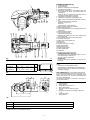
Installation operations are now at the stage where the
blast tube and sleeve are secured to the boiler as shown
in fig. (A). It is now a very simple matter to set up the
combustion head, as this depends solely on the MAX
output developed by the burner.
It is therefore essential to establish this value before proceeding to set up the combustion head.
There are two adjustments to make on the head:
• air delivery R1;
• gas delivery R2.
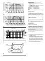
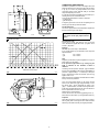
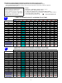
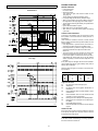
In diagram (C) find the notch to use for adjusting the air
and the gas, and then proceed as follows:
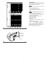
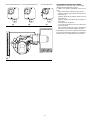
Air adjustment (A)
Turn screw 4)(A) until the notch identified is aligned with
the front surface 5)(A) of the flange.
IMPORTANT: In order to facilitate adjustment, loosen screw 6)(A), adjust and then
tighten.
D1256
(B)
(A)
Notches (Air=Gas)
Gas adjustment (B)
Loosen the 3 screws 1)(B) and turn ring 2) until the
notch identified is aligned with index 3). Tighten the 3
screws 1) fully down.
Example
RS 68/M LN, burner output = 1894 MBtu/hr
If we consult diagram (C) we find that for this output the
adjustments are:
• air:
R1 = notch 6;
• gas:
R2 = notch 2.
Note
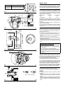
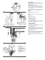
Diagram (C) indicates an optimal regulation for a type of
boiler seen in fig. (B) page 5.
If the pressure of gas allows it, by closing ring nut
2)(B) a reduction of the formation of NOx is
obtained.
Maximum burner output
(C)
D2797
Continuing with the previous example, page 6 indicates
that for burner RS 68/M LN with output of 1894 MBtu/hr a
pressure of approximately 2” is necessary at test point
6)(A). If this pressure cannot be reached, open the ring
2)(B) to notch 4 or 5.
Make sure that the combustion characteristics are satisfactory and free of pulsations.
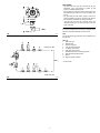
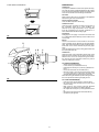
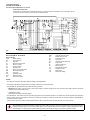
Once you have finished setting up the head, refit the
burner to the slide bars 3)(D) at approximately 4” from
the sleeve 4)(D) ” burner positioned as shown in fig.
(B)p. 7 ” insert the flame rod cable and the ignition electrode cable and then slide the burner up to the sleeve so
that it is positioned as shown in fig. (D).
Refit screws 2) on slide bars 3).
Secure the burner to the sleeve by tightening screw 1).
Reconnect the swivel joint 7) to the graduated sector 6).
(D)
D2376
8
Important
When fitting the burner on the two slide bars, it is advisable to gently draw out the high tension cable and flame
detection probe cable until they are slightly stretched.