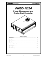
1
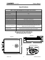
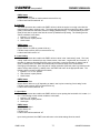
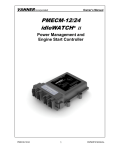
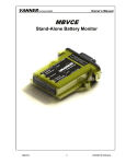
VANNER Incorporated Owner’s Manual PMEC-12/24 Power Management and Engine Start Controller Table of Contents Introduction………………………………………………….………………… 3 Specifications…………………………………………………….………….… 4 Operation……………...………………………………………………………. 5 Installation Instructions…………………………...…………….……………. 10 Typical Application………………………….………...……………………… 14 Troubleshooting………………………………………………………………. 18 PMEC-12/24 1 OWNER‟S MANUAL VANNER Incorporated Owners Manual Notes PMEC-12/24 2 OWNER‟S MANUAL VANNER Incorporated Owners Manual Introduction Thank you for purchasing Vanner‟s PMEC-12/24 Power Management and Engine Start Controller, commonly referred to as IdleWATCH™. The IdleWATCH™ is an idle reduction system that helps fleets meet the industry‟s no-idle regulations in addition to reducing fuel consumption and exhaust emissions. We are confident that you will be very pleased with its performance because Vanner products are designed and manufactured by skilled professionals using the highest standards in workmanship. With minimum maintenance and care, you can be assured of many years of trouble free service. General Description While enabled, the Vanner IdleWATCH™ constantly monitors the state of charge (SOC) and state of health (SOH) of a vehicle‟s auxiliary batteries for the purpose of automatically controlling loads and starting the engine to recharge the batteries. This enables a worker to run 12V or 24V loads, without the engine running, without the worry of discharging the batteries. When the auxiliary batteries are discharged to a user configurable “engine on” state of charge, the IdleWATCH™ sends a signal to a remote starter* to start the engine and recharge the batteries. Fast idle mode* will be employed during the recharge cycle if it is necessary. Once the battery‟s “engine off” state of charge is achieved, the IdleWATCH™ will automatically turn the engine off. The IdleWATCH™ is J1939 CAN (Controller Area Network) enabled and is fully configurable over a J1939 compliant network. (Reference the Vanner CAN Interface User Manual for configuration instructions.) A typical IdleWATCH™ system consists of the following; 1) PMEC-12/24 a) Main power and control circuitry housed in an anodized aluminum extrusion b) 33 position Deutsch panel mounted connector for vehicle I/O and CAN communications c) Three 5/16 studs for main 100A – 12 or 24V input and two 50A switched outputs 2) Panel Mounted Remote a) Enables and disables IdleWATCH™ system b) Dash mounted 3) Current Sensor (VSS-C80/600 or VSS-C80) a) Toroid style current sensor b) One or more current sensors may be required depending on system configuration 4) Battery Voltage and Temperature Sensor (VSS-VT) a) Stud mounted sensor for monitoring battery voltage and temperature Note: The vehicle remote starter and fast idle controls are not part of the IdleWATCH™ system. They are aftermarket accessories that are controlled by output signals from the IdleWATCH™. PMEC-12/24 3 OWNER‟S MANUAL VANNER Incorporated Owners Manual Specifications PMEC-12/24 Power Management and Engine Start Controller Model Number Input Voltage Range (VDC) Efficiency (Peak) Max Input Current (AMPS) Output Voltage Range (VDC) Max Output Current (AMPS) Max Ripple Voltage (mV) Standby Current (Milliamps) Cooling Method Operating Temp. Storage Temp. Serviceable PMEC-12/24 8 – 32 91% 100 8 - 32 2 x 50 <100mV RMS <20mA @ 24V, <40mA @ 12V Convection -40°C to +60°C (-40°F to 140°F) -40°C to +85°C (-40°F to 185°F) Internal components to be serviced by Vanner personnel only. Environmental Considerations Anodized aluminum enclosure provides protection against salt, fungus, dust, water, fuel vapors and all fluids associated with commercial and offhighway vehicle operations. IP55 Rated. Mounting Location Weight (lbs.) Mount on a flat surface close to the batteries to permit short cable runs. Location should be protected from battery acid and gases. 5 lbs (2.3kG) Dimensional Specifications (All Dimensions are in Inches) Side View .Top View 3.26 10.50 Panel Mounted Remote 8.50 2.60 Engine Start 1.55 Autostart Off Fast Idle Enable PMEC-12/24 4 OWNER‟S MANUAL VANNER Incorporated OWNER’S MANUAL Theory of Operation Battery Monitoring The primary function of the PMEC is battery monitoring. The monitoring algorithm analyzes battery voltage, current, and temperature inputs, and calculates/estimates the SOC (State of Charge), SOH (State of Health), SOCach (Achievable State of Charge based on SOH and temperature of battery), U (Estimated Time to Run), and Up (Estimated Time to Run adjusted by SOH and temperature of battery) of the battery. Battery Profile The characteristics of a battery differ by type, manufacturer, and capacity. It is critical to use the appropriate battery profile for accurate battery monitoring. Currently, eight different battery profiles are stored in the PMEC software: (1) (2) (3) (4) (5) (6) (7) (8) East Penn 8A31DT East Penn 8A31DT x 2 (two batteries connected in parallel) Deka 7T31 Deka 7T31 x 2 (two batteries connected in parallel) Deka Dominator 8G31 Deka Dominator 8G31 x 2 (two batteries connected in parallel) Lifeline GPL-8DL Lifeline GPL-8DL x 2 (two batteries connected in parallel) Note: See “Key Sense and System Voltage Level Configuration” on page 7 for series and parallel setting for 12V and 24V systems. Select the proper profile to match the vehicle battery for optimal estimations. If the vehicle battery parameters differ from the above profiles, the Vanner CAN interface software allows the user to enter battery parameters via CAN bus. Please reference the Vanner CAN Interface User Manual which is available at http://www.vanner.com/vp/manuals.htm. Alternatively, the user can send the battery parameters to Vanner and let Vanner load the new battery profile into the software. A list of battery parameters used by the software is shown in Table 1. No 1 2 3 4 5 6 7 8 9 10 11 12 13 14 15 PMEC-12/24 Table 1: List of battery parameters used by PMEC software Symbol Description Nj Number of cells in battery Nb Number of batteries connected in parallel Ef0_60 Charging efficiency when SOC is between 0-60% Ef60_80 Charging efficiency when SOC is between 60%-80% Ef80_90 Charging efficiency when SOC is between 80%-90% Ef90_95 Charging efficiency when SOC is between 90%-95% Ef95_100 Charging efficiency when SOC is between 95%-100% C Peukerts Amp-hour rating of battery n Peukerts number of battery Tc Temperature constant of battery Tr Rated temperature of battery Ve Endpoint voltage of battery thC Charge current threshold thD Discharge current threshold thBC Boost charge current threshold 5 OWNER‟S MANUAL VANNER Incorporated 16 17 18 19 20 thS thCS BCC Ahr Chr OWNER’S MANUAL Start current threshold Cold start current threshold Battery cranking current Amp-hour rating of battery C rating for Ahr Engine Control Engine control is turned on if the “Auto Start” function is enabled from the remote control by pressing and holding the two enable keys for three seconds (see illustration of remote on page 4). Engine control is based on the battery SOC estimated from the battery monitoring module, the battery charging current, and some predefined parameters that are outlined in Table 2. These engine control parameters can be configured via Vanner‟s CAN interface software. Please reference the Vanner CAN Interface User Manual which is available at http://www.vanner.com/vp/manuals.htm. No 1 2 3 4 5 6 7 Table 2: List of Engine Control Parameters used by PMEC software Symbol Description SOC_EngineOn SOC setpoint to turn on engine SOC_EngineOff SOC setpoint to turn off engine SOC_LoadOff SOC setpoint to turn off all loads TopOffChargeEnable Top off charge enable control TopOffChargeCycles Number of charge/discharge cycles to top off charge AltMaxVoltage Maximum alternator voltage FastIdleCurrent Charging current setpoint for fast idle control When “Auto Start” is enabled, the engine control logic is as follows; If battery SOCach < SOC_EngineOn then start engine. If battery SOC > SOC_EngineOff then stop engine. Every TopOffChargeCycles charge/discharge cycle allows a top off charge (100% SOC, or 2 hours beyond SOC_EngineOff) if TopOffChargeEnable is enabled. If the average charge current is less than FastIdleCurrent and alternator voltage is 0.5V lower than AltMaxVoltage then fast idle is enabled. If alternator is > 0.5V below AltMaxVoltage at full voltage and charge current is lower than FastIdleCurrent then fast idle is disabled unless that results in low charge current. When Auto Start is enabled, the time to turn on the engine is also estimated by the battery monitoring subroutine. The number of charge/discharge cycles before the next top off charge is also updated. Load Control Parameters Table 3 lists several load control parameters that can be configured via Vanner‟s CAN interface software. Please reference the Vanner CAN Interface User Manual which is available at http://www.vanner.com/vp/manuals.htm. No 1 2 3 PMEC-12/24 Table 3: List of Engine Control Parameters used by PMEC software Symbol Description LoadALimit Load A current limit LoadBLimit Load B current limit LoadRestartTime Time to restart load after over current 6 OWNER‟S MANUAL VANNER Incorporated OWNER’S MANUAL Load Control There are two load outputs, labeled as Load A and Load B. Both loads will be shut off if the battery SOC is less than SOC_LoadOff, which can be set through the CAN bus. Each load will be shut off if the corresponding load current is higher than its Load?Limit, which can be set through the CAN bus. (Here „?‟ denotes either A or B.) Loads are also controlled based on the status of the following inputs: Park Switch Hood Switch Auto Start Ignition Key Sense When ignition is off and Auto Start is enabled, both Load A and Load B are turned on. When key is in or hood is open, Auto Start will be disabled. When ignition is on but transmission is still on park, both Load A and Load B will be turned off. When ignition is on and transmission is out of park (driving mode), Load B will be turned on while Load A is turned off. Note: A zero to sixty second user configurable time delay, LoadBOffDelay, is present to delay Load B turning off after putting the transmission in park. Key Sense and System Voltage Level Configuration Key sense signal can be configured via CAN bus. It can be configured as Active High Active Low Not Available If key sense is not available, ignition switch status will be used to control and Auto Start and Loads. System voltage level can be configured via CAN bus. The available configurations are Single 12V – with only 12V battery and loads Single 24V – with two 12V batteries connected in series. Only 24V loads are used Dual 24V/12V – with two 12V batteries connected in series. Both 24V loads and 12V loads are available Note: Do NOT change Nj (number of cells per battery) from 6 to 12 for 24V system. Choose appropriate system voltage level instead. Reference the table below to assist with selecting the proper battery parameter profile for your battery configuration. Configuration +24V + +24V +24V - + + - +12V + - - + + - GND + + GND - - + - + - +12V +12V +12V GND +24V - + - + - + GND - + - + GND GND Profile 0,2,4,6 0,2,4,6 0,2,4,6 1,3,5,7 1,3,5,7 1,3,5,7 Nj 6 6 6 6 6 6 Nb 1 1 1 2 2 2 Voltage Level 24/12V Dual 24V Single 12V Single 24/12V Dual 24V Single 12V Single PMEC-12/24 7 - OWNER‟S MANUAL VANNER Incorporated OWNER’S MANUAL Saving of Battery Data at Power Down An unmaskable external interrupt will be triggered when the ignition signal to the PMEC drops below 9V. In this interrupt service routine, all PMEC/battery parameters and battery status information is saved into non-volatile memory – FRAM. The saved data is read out at power up and used to continue battery monitoring. By doing this, the battery monitor can always start from the previous state instead of restarting from the default state. In case the saved data is corrupted for any reason, software will load default values and start from the default state. Factory reset sets all parameters and battery state data to their default values. CAUTION: Do not reset IdleWATCH™ parameters to factory defaults while the truck is running or the batteries are discharged. Inaccuracies in battery states will be introduced that will adversely affect system performance. CAN Communication J1939 CAN communication is supported by the PMEC. The following CAN messages are handled; Heartbeat PMEC status Battery voltage and current Load current Battery status Read and set PMEC/battery parameters DM1 messages Data logging CAN bootloader Please refer to the Vanner PMEC CAN Specification for details. Data Logging Battery and PMEC status information can be logged in two RAM chips (if populated) at a userspecified rate. The logged data will be lost if the ignition signal to the PMEC is turned off but it can be read out before that via CAN bus. The PMEC dashboard in the Vanner CAN Interface provides this reading function. The maximum number of records that can be logged and read is 16384. Battery and PMEC status data can be displayed and saved to a text file via the PMEC dashboard. The text file can be imported later into Microsoft Excel for analysis. The user can specify the data logging speed (interval in seconds between two data records) and length (number of data records to log). The logging speed can be chosen from 1 record per second to 1 record per hour. The corresponding logging interval is 1 through 3600 (seconds). The logging length can be 1 through 16384. Data logging will stop when the specified number of records is logged. The user can specify a length greater than 16384 to enable continuous data logging. Please note that even in continuous mode, a maximum of 16384 data records can be logged into the RAM chip. However, when this number is reached, new data will overwrite the old data to continue logging. Short Circuit – Thermal – ESD (Electrostatic Discharge) – Overvoltage Protection The PMEC utilizes smart FET power switching devices that have short circuit, over-temperature, ESD and overvoltage protections built in. PMEC-12/24 8 OWNER‟S MANUAL 9 op en ho od open hood Pr e bu ss a tto nd n fo hol r1 d se disa co b nd le en op od ho Press and hold disable button for 1 second Press and hold disable button for 1 second AutoStart: disabled Engine Start: off Fast Idle: off Load A: off Load B: off Ignition: off ParkSwitch: park HoodSwitch: open 7 - hood open close hood AutoStart: disabled Engine Start: off Fast Idle: off Load A: off Load B: off Press and hold both enable buttons for 3 seconds 1 - auto start AutoStart: enabled Engine Start: off Fast Idle: off Load A: on Load B: on Ignition: off ParkSwitch: park HoodSwitch: close AutoStart: enabled Engine Start: on Fast Idle: off Load A: on Load B: on Ignition: on ParkSwitch: park HoodSwitch: close 4 - engine start SOC >= SOC_EngineOff and SOCach > SOC_EngineOn+3 AutoStart: enabled Engine Start: on Fast Idle: on Load A: on Load B: on Ignition: on ParkSwitch: park HoodSwitch: close 5 - fast idle Vbatt >= AltMaxVoltage-0.5 & Ibatt <= FastIdleCurrent 0 - initial SOCach <= SOC_EngineOn PMEC-12/24 Vbatt < AltMaxVoltage-0.5 & Ibatt <= FastIdleCurrent Ignition: off ParkSwitch: park HoodSwitch: close key out h > SO C f 6 - load cutting ad Of AutoStart: disabled Engine Start: off Fast Idle: off Load A: off Load B: off SO C_ Lo _L oa dO ff <= ch Ca SO = h< ac C SO > f AutoStart: enabled Engine Start: xxx Fast Idle: xxx Load A: off Load B: off ff dO oa L C_ SO f dO oa L C_ SO SOCach > SOC_LoadOff transmisson out of park AutoStart: disabled Engine Start: off Fast Idle: off Load A: off Load B: on PMEC State Diagram Rev 1.2 Note: For 24V/12V dual voltage system, the SOC and SOCach of the two batteries may be different. Average values of the two batteries are used in engine start control. (Load B turned off with CANconfigurable delay) transmisson in park 3 - driving Ignition: on ParkSwitch: drive HoodSwitch: close 2 - key in Ignition: xxx ParkSwitch: park HoodSwitch: close SOCach <= SOC_LoadOff Ignition: xxx ParkSwitch: park HoodSwitch: close SO Ca c Ca ch SO key in ignition off VANNER Incorporated OWNER’S MANUAL State Diagram - Graphical OWNER‟S MANUAL VANNER Incorporated OWNER’S MANUAL State Diagram - Descriptive 0 - Initial This state represents the condition the vehicle will be in prior to any human interaction. 1 – Auto Start This state represents the condition the PMEC will be in after enabling AutoStart functionality upon arrival at a job site. In order for AutoStart functionality to be enabled, the following vehicle conditions must be met; 1. Ignition in “off” position (no key present) 2. Gear selector in park position 3. Hood closed PMEC States As long as the battery SOC is >= SOC_EngineOFF, the engine will not start. Both Load A and Load B will be switched “on”. 2 – Key In This state represents the condition the PMEC will be in when the following vehicle conditions are met; 1. Key in barrel 2. Ignition in either “on” or “off” position 3. Gear selector in park position 4. Hood closed PMEC States AutoStart functionality is disabled Both Load A and Load B will be switched “off” 3 – Driving This state represents the condition the PMEC will be in while the vehicle is being driven. The following are the vehicle conditions in this state; 1. Ignition in “on” position 2. Gear selector out of park 3. Hood closed PMEC States AutoStart functionality is disabled Load A will be switched “off” Load B will be switched “on” Note: Load B turned off with CAN-configurable delay (0 – 60 Seconds) 4 – Engine Start This state represents the condition the PMEC will be in while the engine is running during a battery recharge cycle. The engine will start if the state of charge achievable (SOCach) is less than or equal to the state of charge engine on (SOC_EngineON) setting. The following are the vehicle conditions in this state; 1. Ignition in “on” position 2. Gear selector in park position 3. Hood closed PMEC-12/24 10 OWNER‟S MANUAL VANNER Incorporated OWNER’S MANUAL PMEC States AutoStart is enabled Engine Start is on (LED on dash mounted remote will be on) Loads A and B will be switched “on” 5 – Fast Idle This state represents the condition the PMEC will be in while the engine is running in the fast idle mode during a battery recharge cycle. The engine will enter the fast idle mode if the battery voltage (Vbatt) is less than the alternator maximum voltage (AltMaxVoltage) – 0.5 and the battery current (Ibatt) is less than or equal to the fast idle current (FastIdleCurrent) setting. The following are the vehicle conditions in this state; 1. Ignition in “on” position 2. Gear selector in park position 3. Hood closed PMEC States AutoStart is enabled Engine Start is on (LED on remote will be on) Fast idle mode is active (LED on remote will be on) Loads A and B will remain “on” 6 – Load Cutting This state represents the condition the PMEC will be in while in the “load cutting” mode. The “load cutting” mode can be entered from any of three modes, “auto start”, “engine start” and “fast idle”. If the state of charge achievable (SOCach) value is less than or equal to the state of charge load off (SOC_LoadOff) value, the PMEC will automatically turn loads A and B off to accelerate the recharging of the batteries. Once the state of charge achievable (SOCach) value is greater than the state of charge load off (SOC_LoadOff) value, the PMEC will return to the appropriate state. The following are the vehicle conditions in this state; 1. Ignition in “on” or “off” position 2. Gear selector in park position 3. Hood closed PMEC States AutoStart is enabled Engine Start is either on or off depending on state it was in prior to entering “load cutting” mode Fast idle mode is active (LED on remote will be on) Loads A and B will be switched “off” 7 – Hood Open This state represents the condition the PMEC will be in upon opening the hood while it is in state 1, 4 or 5. The following are the vehicle conditions in this state; 1. Ignition in “off” position 2. Gear selector in park position 3. Hood open PMEC States AutoStart is disabled Engine Start is off Fast idle is off Loads A and B will be switched “off” Upon closing the hood, the PMEC state will return to the initial settings found in state 0. PMEC-12/24 11 OWNER‟S MANUAL VANNER Incorporated OWNER’S MANUAL Disabling AutoStart AutoStart functionality can be disabled by pressing and holding the “Off” button for one second. The “Off” button is located on the panel mounted remote. Upon disabling AutoStart, the PMEC state will return to the initial settings found in state 0. Turning Ignition Off and/or Returning Gear Selector to Park If the ignition is turned off and the key removed from the ignition while in state 2, the PMEC will return to the initial settings found in state 0. If the gear selector is returned to park, the ignition turned off and the key removed while in state 3, the PMEC will return to the initial settings found in state 0. Note: This assumes that vehicle is provisioned with key sense circuitry. PMEC-12/24 12 OWNER‟S MANUAL VANNER Incorporated OWNER’S MANUAL Installation Instructions These symbols are used to note procedures that if not closely followed could lead to loss of life or damage to equipment or property due to electrocution. Electrocution hazard exists Fire hazard exists A potentially dangerous condition Explosive hazard exists Corrosive hazard exists Do not exceed the specified torque of 120 in-lbs. when connecting cables to the terminal posts (+24, GND, +12) during installation of all the PMEC Models. Torque values higher than specified may damage the product, reduce performance, and/or create hazardous conditions. Products damaged by improper torque are not covered by the warranty. Do not connect more than one conductor per terminal post on the Vanner PMEC. Multiple wires and cables may overstress internal components, resulting in poor performance or creating hazardous conditions. Products damaged by the installation of multiple conductors per post are not covered by the warranty. Fault protection devices must be installed between the PMEC and the power source (battery). A fault protection device would be any fuse or circuit breaker properly rated for the maximum DC current obtainable. This advisory is in accordance with SAE, NEC and UL, for mobile power applications. Install per applicable codes or within 18” of the battery. See Wire and Fuse Sizing Chart on page 15 of this manual or contact Vanner at 1-800-227-6937 or [email protected] if assistance is needed in sizing fault protection devices. Caution: This equipment tends to produce arcs and sparks during installation. To prevent fire or explosion, compartments containing batteries or flammable materials must be properly ventilated. Safety goggles should always be worn when working near batteries Mounting Location –The PMEC may be mounted in any orientation, on a flat mounting surface suitable to support the PMEC during application. Do not mount in zero-clearance compartment that may result in the PMEC overheating. Locate so that contact by people is unlikely. PMEC-12/24 13 OWNER‟S MANUAL VANNER Incorporated OWNER’S MANUAL Mounting Dimensions (Top View – Dimensions are in Inches) 7.94 0.25 TYP PMEC-12/24 Power Management - Engine Control Interface Mating Deutsch hardware: Plug - HDP26-24-33SN Terminal 16-20Awg 1062-20-0122 Power 8.00 spec label Experience Power... Experience Vanner www.vanner.com 1.800.AC POWER Output B 50A Input 100A Output A 50A Environmental Protection – Your PMEC has been designed to withstand direct exposure to rain and moisture. The PMEC has also been tested for exposure to direct pressure spray, but continual exposure to direct pressure spraying may reduce the PMEC serviceable life. Any damage due to water contamination is covered by Vanner only through the terms of our factory warranty. Wiring Sequence– The PMEC is internally protected for reverse polarity. The wiring sequence is not an issue with the PMEC product. PMEC-12/24 14 OWNER‟S MANUAL VANNER Incorporated OWNER’S MANUAL PMEC-12/24 Input/Output Definitions Deutsch HDP24-24-33PN Mating Connector: Deutsch HDP26-24-33SN Mating Contacts: Deutsch 1062-20-0122 33 32 14 12 19 7 1 4 29 Green “Power” LED 6 5 13 28 18 15 31 30 17 16 21 9 3 11 20 8 2 10 27 23 26 25 24 Output B – 50A Input – 100A Output A – 50A 5/16-18 Stud, Typ Pin 1 2 3 4 5 6 7 8 9 10 11 12 13 14 15 16 17 Deutsch 33 Position Pin Assignments Description Pin Description CT12V – Low 18 CT24V – Sensor Gnd CT12V – High 19 CT24V - +5V Supply CT12V – Sensor Gnd 20 Hood Switch Fast Idle (Remote Indicator) 21 CAN Low Engine Start (Remote Indicator) 22 CAN Shield 12V Battery Temp Sensor Ground 23 CAN High 12V Battery Temp Sensor +5V Supply 24 Remote Switch Disable Park Switch 25 +5V Remote Supply CT12V - +5V Supply 26 Key Sense Remote Switch Enable 27 Power Ground Remote Ground 28 Power Ground Auto Start Enabled (Remote Indicator) 29 Auto Start Enabled Fast Idle 30 Engine Start Sense Negative 31 Ignition (12V or 24V) 12V Battery Temp Sensor +12V 32 12V Battery Temp Sensor CT24V – Low 33 +24V Sense CT24V – High Color Legend 12V Current Sensor Leads Remote Leads Voltage and Temperature Sensor Leads 24V Current Sensor Leads CAN Communication Leads Vehicle I/O PMEC-12/24 15 OWNER‟S MANUAL 22 VANNER Incorporated OWNER’S MANUAL PMEC-12/24 Remote Input/Output Definitions Connector on Rear of Remote Engine Start Autostart Off Fast Idle 4 3 2 1 8 7 6 5 Enable Tyco 1-794065-0 Mating Connector: Tyco 770579-1 Mating Contacts: Tyco 171639-1 Pin 1 2 3 4 5 6 7 8 Remote Pin Assignments Description +5V Ground Switch Enable Spare Switch Disable Auto-Start Enable Engine Start Fast Idle Remote Functionality The PMEC remote serves as a status indicator in addition to allowing the user to enable auto start functionality. The auto start feature is enabled by simultaneously pressing and holding the two “Enable” buttons, approximately three seconds, on the left side of the remote. When the auto start feature is enabled, the “Autostart” LED will turn on. The “Engine Start” LED turns on when the “Engine Start” signal is received from the PMEC. The “Fast Idle” LED turns on when the “Fast Idle” signal is received from the PMEC. The auto start feature is disabled by simply pressing the “Off” button on the right side of the remote. The green “Autostart” LED will turn off. The following are conditional inputs that will also disable the auto start feature; 1. Inserting key in ignition (if key sense option is present) 2. Ignition on 3. Moving transmission out of park 4. Opening the hood PMEC-12/24 16 OWNER‟S MANUAL VANNER Incorporated OWNER’S MANUAL Typical Application/Wiring 12V Auxiliary Battery with 12V Loads PANEL MOUNTED REMOTE Engine Start Autostart Off Fast Idle Enable PMEC-12/24 Power Management - Engine Control VEHICLE INPUTS Interface Mating Deutsch hardware: Plug - HDP26-24-33SN Terminal 16-20Awg 0462-201-16141 KEY SENSE IGNITION SWITCH Power PARKING SWITCH HOOD SWITCH spec label OUTPUT SIGNALS AUTO START ENABLE Experience Power ... Experience Vanner www.vanner.com 1.800.AC POWER Output B 50A Input 100A START ENGINE Output A 50A TO "B" LOADS 50A MAX TO "A" LOADS 50A MAX FAST IDLE CAN I/O HI LOW SHIELD F1 + DUAL CURRENT SENSOR 80/600A TEMP/ VOLTAGE SENSOR 12V AUX BATTERY - + 12V ALT - PMEC-12/24 +12V LOADS 17 OWNER‟S MANUAL VANNER Incorporated OWNER’S MANUAL Typical Application/Wiring 24V Auxiliary Batteries with 24V Loads PANEL MOUNTED REMOTE Engine Start Autostart Off Fast Idle Enable PMEC-12/24 Power Management - Engine Control VEHICLE INPUTS Interface Mating Deutsch hardware: Plug - HDP26-24-33SN Terminal 16-20Awg 0462-201-16141 KEY SENSE IGNITION SWITCH Power PARKING SWITCH HOOD SWITCH spec label OUTPUT SIGNALS Experience Power ... Experience Vanner AUTO START ENABLE www.vanner.com 1.800.AC POWER Output B 50A Input 100A Output A 50A START ENGINE TO "B" LOADS 50A MAX TO "A" LOADS 50A MAX FAST IDLE CAN I/O HI LOW SHIELD F1 + DUAL CURRENT SENSOR 80/600A TEMP/ VOLTAGE SENSOR 12V BATTERY B PMEC-12/24 +24V LOADS - 18 12V BATTERY A + + 24V ALT - OWNER‟S MANUAL VANNER Incorporated OWNER’S MANUAL Typical Application/Wiring 24V Auxiliary Batteries with 12V Loads Requiring a Battery Equalizer Engine Start Autostart Off PANEL MOUNTED REMOTE Fast Idle Enable PMEC-12/24 Power Management - Engine Control VEHICLE INPUTS Interface Mating Deutsch hardware: Plug - HDP26-24-33SN Terminal 16-20Awg 1062-20-0122 KEY SENSE IGNITION SWITCH Power PARKING SWITCH HOOD SWITCH spec label OUTPUT SIGNALS AUTO START ENABLE Experience Power ... Experience Vanner www.vanner.com 1.800.AC POWER Output B 50A Input 100A START ENGINE Output A 50A F1 TO "A" LOADS 50A MAX TO "B" LOADS 50A MAX FAST IDLE CAN I/O HI LOW SHIELD F2 CT24V DUAL 80/600 + 12V BATTERY B TEMP/VOLT SENSOR - +24V CT12V DUAL 80/600 Equalizer F3 +12V + GND - + 12V BATTERY A 24V ALT - PMEC-12/24 +24V LOADS +12V LOADS - 19 OWNER‟S MANUAL VANNER Incorporated OWNER’S MANUAL PMEC-12/24 I/O Definitions and Functionality CT12V - Low: Low range current sense signal (0 – 80A) on 12V battery CT12V - High: High range current sense signal (0 – 600A) on 12V battery CT12V – Sensor Ground: Ground to current sensor Fast Idle (Remote Indicator): Signal to remote for visual indication engine is in fast idle mode 5. Engine Start (Remote Indicator): Signal to remote for visual indication during engine starting and running. 6. 12V Temp Sensor Ground: Ground to voltage and temperature sensor 7. +5V (Temp Sensor Supply): Power to voltage and temperature sensor 8. Park Switch: Parking switch input from vehicle – ground when transmission is in park/neutral 9. CT12V +5V Supply: Power to 12V current sensor 10. Remote Switch Enable: Signal from remote enabling Engine Auto Start functionality 11. Remote Ground: Ground to remote 12. Auto Start Enabled (Remote Indicator): Signal to remote for visual indication that “Auto Start” functionality is enabled 13. Fast Idle: Signal to vehicle controls enabling fast idle – ground when fast idle is commanded 14. Sense Negative: Battery negative (ground) terminal for voltage sensing 15. Sense +12V: Battery positive terminal for voltage sensing – integral to temperature sensor 16. CT24V - Low: Low range current sense signal (0 – 80A) on 24V battery 17. CT24V - High: High range current sense signal (0 – 600A) on 24V battery 18. CT24V – Sensor Ground: Ground to current sensor 19. CT24V +5V Supply: Power to 24V current sensor 20. Hood Switch: Hood switch input from vehicle – ground when hood is open 21. CAN Low: Low signal connection for CAN bus 22. Can Shield: Shield connection for CAN bus 23. CAN High: High signal connection for CAN bus. CAN bus used for system configuration with Vanner CAN interface software. 24. Remote Switch Disable: Signal from remote disabling Engine Auto Start functionality 25. +5V Remote Supply: Power to remote 26. Key Sense: 12/24V detection of key presence configurable as active hi, lo or not available 27. Power Ground: Battery negative (ground) terminal for power 28. Power Ground: Battery negative (ground) terminal for power 29. Auto Start Enabled: +12/24V 5A output signal for visual or audible indication that Auto Start functionality is enabled 30. Engine Start: Signal to vehicle controls to start engine – ground when engine start is commanded 31. Ignition (12V or 24V): 12 or 24V signal from ignition 32. 12V Battery Temp Sensor: Temperature signal from battery temp sensor 33. +24V Sense: +24V signal from battery 1. 2. 3. 4. Note: The PMEC I/O is a panel mounted Deutsch connector P/N: HDP24-24-33PN. Use Deutsch P/N: HDP26-24-33SN with Deutsch P/N: 1062-20-0122 socket contacts for the mating connector. The accepted wire size for the sockets is 16, 18 or 20 AWG with an insulation outside diameter of .075 – .125”. PMEC-12/24 20 OWNER‟S MANUAL VANNER Incorporated OWNER’S MANUAL Wire Size and Temperature Rating Cables connecting the PMEC to the batteries should be sufficiently sized to prevent unwanted voltage drop. Vanner recommends the voltage drop should be no greater than 0.5 between the PMEC‟s +12/24 volt terminal and the battery +12/24 volt terminal. In most installations, the PMEC’s terminals should be wired directly to the battery terminals (reference fault protection) to prevent voltage drop that could occur in switch contacts, connections, and long wire runs. Since the PMEC can be operated in temperatures up to 60ºC, use wire rated at least 90ºC. See the Wire and Fuse Size Chart below. PMEC Wire and Fuse Size Chart Wire Size AWG Ring Terminal AMP or UL recognized equal #4 #2 #1 33470 322870 321867 Max wire length, in feet, between PMEC and battery to keep voltage drop under 0.5 volts. The chart assumes wire carries no other load and wire temperature is below 80ºC. PMEC-12/24 15.9 25.7 31.6 Fuse Designation Current Rating Fuse F1 Fuse F2 Fuse F3 125 Amp * * Vanner Part # Fuse 013912 * * Vanner Part # Fuse Holder 013780 * * * Note: Fuse F2 and Fuse F3 are dependent on the current rating of the equalizer. Please contact Vanner at 1-800-AC POWER (1-800-227-6937) to properly size the equalizer and fuses for your system. PMEC-12/24 21 OWNER‟S MANUAL VANNER Incorporated OWNER’S MANUAL Troubleshooting CAUTION Servicing of electrical systems should only be performed by trained and qualified technical personnel. Equipment Required VoltMeter having 0.01 volt resolution. (Fluke Model 87 Multimeter recommended). Clamp-on current meter (Fluke Model 36 Clamp-on Meter recommended). USB to CAN adapter module - PEAK System‟s PCAN-USB IPEH-002021 or Vector‟s CANcaseXL V2.0 w/CANpiggy 1050mag installed Laptop computer with Vanner CAN interface software. Vanner Repair Service Vanner offers a quick turn-around factory repair service. Send the unit to the address on last page with a note instructing us to repair it. Include your name, phone number, shipping address (not a P.O. Box Number), and your purchase order number. Trouble Shooting Guide for PMEC PMEC-12/24 Trouble Shooting Guide: In the event the Vanner PMEC does not work properly, the following need to be reviewed / validated; 1. Is voltage present at the 100A input terminal? This can be verified with a voltmeter or by checking that the green “Power” led is lit. 2. Is the I/O wiring installed correctly? (Reference pin-out assignments on page 15.) 3. Is the current sensor installed in the proper orientation? (Reference wiring diagrams on pages 17 19.) 4. Is the voltage / temperature sensor installed on the proper battery terminal? (Reference wiring diagrams on pages 17 - 19.) 5. Are the fuse voltage and current ratings correct? PMEC-12/24 22 OWNER‟S MANUAL VANNER Incorporated OWNER’S MANUAL Notes PMEC-12/24 23 OWNER‟S MANUAL VANNER Incorporated OWNER’S MANUAL Vanner Incorporated 4282 Reynolds Drive Hilliard, Ohio 43026 1-800-AC POWER (1-800-227-6937) Tel: 614-771-2718 Fax: 614-771-4904 www.vanner.com e-mail: [email protected] Part Number D914929-C November 9, 2010 Printed in U.S.A. PMEC-12/24 24 OWNER‟S MANUAL