1
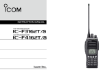
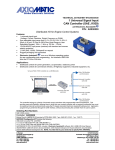
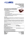
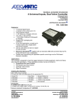
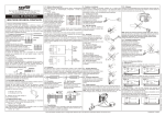
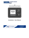
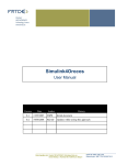
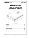
Preliminary TECHNICAL DATASHEET #TDAX100250 25A BLDC MOTOR CONTROLLER P/N: AX100250 Variable Speed Control, Onboard I/O CAN SAE J1939, Rugged Packaging with Electronic Assistant® Features: Y AR IN IM EL Unidirectional or bi-directional BLDC motor control Up to 25A continuous output current to the motor (400 W) Hall Effect Sensor Feedback Flexible control open loop speed control; closed loop speed control (on request); external feedback control (on request). 2 Universal inputs are user configurable from the following: 0-5V; 0-10V; 0-20 mA; 4-20 mA; frequency; PWM; or digital (pull up - pull down). The control input to drive the motor can be mapped to either of the 2 universal inputs or the controller can respond to messages from a CAN bus. 2 Digital inputs (pull up - pull down) User configurable enable function can be mapped to any of the 2 digital inputs or a CAN message Direction control can be mapped to any of the 2 digital inputs or a CAN message 1 current output (3A proportional or hotshot digital) is available to drive accessories such as hydraulic valves or relays for machine control or safety interlock. Output can be coded as feedback messages sent to the CAN bus 1 Frequency output provided to follow the rotation speed of the motor Two reference voltages (5V, 50 mA max.) are provided to power external sensors or potentiometers Highly efficient and robust design with isolation for drive and processing circuits Operational from 9 to 32 Vdc (12 or 24 Vdc nominal) 2 CAN ports (SAE J1939) are provided (CANopen on request) Electronic Assistant® runs on a Windows operating system for simple user configuration. An Axiomatic USB-CAN converter links the PC to the CAN bus. Compact size for easy mounting on a vehicle Suitable for moist, high shock and vibration environments Fully sealed with a rugged IP67 corrosion resistant aluminum housing Operational from -40 to 75C (-40 to 167F) A Simulink® Development Kit with block library is available on request. PR Applications: Motor variable speed, position and/or flow control in Lift Equipment, Electric Vehicles for Material Handling, Trucks, Cranes and Hoists, Hydraulic Tail Lifts and Winches, Golf Carts, Military Equipment, Mobile Pumps and Hydraulic Powerpacks Ordering Part Numbers: BLDC Motor Controller P/N: AX100250 Configuration Tool: Electronic Assistant® P/N: AX070502 Accessories: Mating Plugs Kit P/N: AX070410 A Simulink® Development Kit with block library is available on request. Y AR IN IM EL Figure 1 - Block Diagram Technical Specifications: PR All specifications are typical at nominal input voltage and 25 degrees C unless otherwise specified. Input Specifications Power Supply Input - Nominal Surge Protection Under-voltage Protection Universal Inputs Digital Input Analog/Digital Ground Digital Ground Motor Feedback TDAX100250-B 12 or 24Vdc nominal (9…32 Vdc) Provided Built-in 2 universal inputs (0-5V, 0-10V, 0-20 mA, 4-20 mA or digital) Input properties are user configurable. Refer to the block diagram and Table 1.0. Any input on the controller can be coded into a Proprietary B message that can be sent to the CAN network. 2 digital inputs are provided. Refer to Table 1.0. 2 Provided 2 Provided Hall Effect Sensor 2 Table 1.0 Inputs to AX100250 (Up to 4 user selectable inputs) Input Type Description Universal Analog Inputs Up to 2 analog inputs are available. 0…5VDC or 0…10VDC The offset is in millivolts and the resolution is mV/bit, when sending a CAN message. Input measurement setpoints are interpreted in volts. 4…20mA or 0…20mA The offset is in microamps and the resolution is μA/bit, when sending a CAN message. Input measurement setpoints are interpreted in milliamps. Frequency PWM Digital Digital Inputs Up to 2 digital inputs are available. These inputs can be used as an enable or direction command for the controller. The input accepted is active high (switch is connected to a +V signal when ON). H-bridge 25A @ 24VDC nominal continuous 25A @ 12VDC nominal continuous Output to Motor Y Output Specifications AR Overcurrent protection is provided. Short circuit protection is provided. The maximum rated speed and motor rated current are configurable to suit individual motor specifications. Shut off with or without ramping Motor direction command can be mapped to any input or come from the CAN bus. Flexible control is provided by user configurable parameters for open loop speed control; closed loop speed control (on request); or external feedback control (on request). The control input to drive the motor can be mapped to either of the 2 universal inputs or the controller can respond to messages from a CAN bus. Thermal protection is built-in and configurable. 1 proportional (0…3A) or hotshot digital (3A) Ramp and dither setpoints are configurable. Hot Shot Coil Saver Outputs (Refer to Figure 2.): The output is on/off with a hotshot current which keeps the load ON with a holding current. This is used as an energy saving method of load control. IN Motor Stop Motor Direction IM Motor Control Mode EL Thermal Protection The output is configurable to send a feedback message to the CAN bus. The feedback is always sent as a word with a resolution of 1 mA/bit, and 0 mA offset. 1 Frequency Output is provided to follow the rotation speed of the motor. 1 Frequency Output GND is provided. Two +5V, 50 mA PR Current Output Frequency Output Reference Voltages HOTSHOT DIGITAL ON INPUT OFF Hotshot Current [mA] OUTPUT Hold Current [mA] 0 [mA] Hotshot Time [ms] TIME Figure 2 – Proportional Output Hotshot Digital Profile TDAX100250-B 3 General Specifications Microprocessor Motor Control Simulink® Block Library The Axiomatic Electronic Assistant® requires an USB-CAN converter to link the device’s CAN port to a Windows-based PC for initial configuration. Order the EA and Axiomatic USB-CAN as a kit (P/N AX070502), which includes all interconnecting cables. Refer to Figure 3. EL IM IN AR Y CAN User Interface STM32F207ZGT7 Standard embedded software is provided. The following parameters are user configurable. Motor Direction: Unidirectional or bi-directional control from an input or the CAN bus. The direction is also configurable. Enable: A universal input can be configured to enable the motor when on. A CAN message can also be used as an enable input. Control Mode: Open loop speed or closed loop speed control (on request) or external feedback control (on request) CAN: CAN bus messages control the motor and/or auxiliary outputs instead of the analog or digital inputs ® Axiomatic can provide a Simulink block library to allow for application ® ® customization. Simulink is a model-based design tool from Mathworks . Refer to the User Manual Axiomatic Hardware Interface Library for Mathworks Simulink for details. Electronic Assistant® for Windows operating systems It comes with a royalty-free license for use. PR Figure 3 - User Configuration Using Electronic Assistant (EA) TDAX100250-B 4 2 CAN ports (SAE J1939) (CANopen on request.) The software was designed to provide flexibility and provides the following. Configurable ECU Instance in the NAME (for multiple ECU’s on the network) Configurable Motor Control Parameters Configurable Motor PID Parameters Configurable Input Parameters Configurable Output Parameters Configurable PGN and Data Parameters Note: Configurable parameters are also called setpoints. The motor controller is compliant with Bosch CAN protocol specification, Rev.2.0, Part B, and the following J1939 standards. Table 2: J1939 Compliance OSI Network Model Layer J1939 Standard Physical J1939/11 – Physical Layer, 250K bit/s, Twisted Shielded Pair. J1939/15 - Reduced Physical Layer, 250K bits/sec, UnShielded Twisted Pair (UTP). Y J1939/21 – Data Link Layer Request (PGN 59904) Acknowledgement (PGN 59392) Transport Protocol – Connection Management (PGN 60416) Transport Protocol – Data Transfer Message (PGN 60160) Proprietary A (PGN 61184) Proprietary B (PGN’s 65280 to 65535) NB. The user can also configure an input channel to send messages to another node using the Proprietary A PGN 61184. AR Data Link CAN Interfaces IN J1939/81 – Network Management J1939, Appendix B – Address and Identity Assignments EL IM Network Layer PR Application Layer Electrical Connections Mounting Packaging and Dimensions Weight Operating Conditions Protection Rating TDAX100250-B Arbitrary Address Capable ECU - It can dynamically change its network address in real time. The controller supports: Address Claimed Messages (PGN 60928) and Commanded Address Messages (PGN 65240). J1939/71 – Vehicle Application Layer None of the application layer PGN’s are supported as part of the default configurations. However, the controller could be configured such that any of the input messages to be sent will use a PGN from this section, or for the outputs to respond to the data in a message with a PGN from this section. The data size, index, resolution and offset can all be configured for the appropriate SPN associated with the PGN. It is the user’s responsibility to configure the controller such that it will not violate the J1939 standard. J1939/73 – Application Layer – Diagnostics DM – Diagnostic messaging (on request) Refer to Table 4. Wires should be of the appropriate gauge to meet requirements of applicable electrical codes and suit the specifications of the connector(s). The motor controller should be mounted as close to the battery and/or the motor as possible. Install the unit with appropriate space available for servicing and for adequate wire harness access and strain relief. Mounting ledges include holes sized for M6 or ¼ inch bolts. The bolt length will be determined by the end-user's mounting plate thickness. Typically 20 mm (3/4 inch) is adequate. Encapsulated in an aluminum extrusion with gasket 8.392 x 6.750 x 3.250 inches 213.16 x 200.03 x 82.55 mm (W x L x H including connectors, excluding mating connectors) Refer to Figure 4.0. 2.25 lbs. (1.02 kg) Operating: -40 to 75C (-40 to 167F) IP67 5 Table 4 - Electrical Pin Out Chart Power Connector (J3) : Deutsch P/N: HD10-6-12P Pin# 1 2 3 4 5 6 Motor Connector (J4): Deutsch P/N: HD10-6-12P Function Batt+ BattNot used Not used Not used Not used Pin# 1 2 3 4 5 6 Function Phase A Out Phase B Out Phase C Out Not used Not used Not used I/O and CAN Connector (J6): Deutsch IPD P/N: HDP24-18-21SN IN IM EL Mating Plug Kit TDAX100250-B Function CAN 1 H CAN 1 L CAN 1 SH +5V Ref. 1 Analog/Digital IN 1 Analog GND +5V Ref. 2 Analog/Digital IN 2 Analog GND Digital IN 3 Digital GND Digital IN 4 Digital GND Frequency Output Frequency Output GND Proportional Output 1 Proportional Output GND CAN 2 H CAN 2 L CAN 2 SH Not Used Y Function P5V_Hall Output Hall A Hall B Hall C Hall GND Not used Not used Not used Not used Not used Not used Not used Not used Not used Not used Not used PR Pin# 1 2 3 4 5 6 7 8 9 10 11 12 13 14 15 16 Pin# 1 2 3 4 5 6 7 8 9 10 11 12 13 14 15 16 17 18 19 20 21 AR Hall Effect Connector (J5): Deutsch IPD P/N: HD10-5-16P A mating plug kit comprised of all mating connectors is available as P/N: AX070410. (2 HD16-6-12S-B010, 0460-204-12141, 0460-203-12141, 114017, HD16-516S, 0460-202-16141, HDP26-18-21PN, 0413-2042005) 6 Y AR Figure 4 - Dimensional Drawing PR EL IM IN Specifications are indicative and subject to change. Actual performance will vary depending on the application and operating conditions. Users should satisfy themselves that the product is suitable for use in the intended application. All our products carry a limited warranty against defects in material and workmanship. Please refer to our Warranty, Application Approvals/Limitations and Return Materials Process as described on www.axiomatic.com/service.html. Form: TDAX100250B-08/13/13 TDAX100250-B 7