1
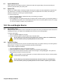
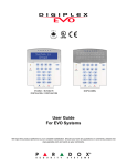
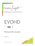
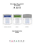
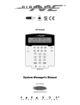
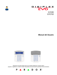
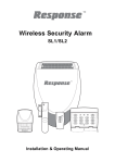
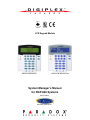
LCD Keypad Module
DGP2-641/DGP2-641R
DGP2-641BL/DGP2-641RB
System Manager’s Manual
for DGP-848 Systems
Also includes
Operating Instructions
Table of Contents
Introduction .................................................................. 1
Legend ............................................................................ 1
Basic Operation ...........................................................
Auditory Feedback (Beep Tones)....................................
Confidential Mode ...........................................................
Partitioned System ..........................................................
Area Status Display.........................................................
1
1
2
2
2
Arming ..........................................................................
Exit Delay Timer ..............................................................
Regular Arming ...............................................................
Stay Arming.....................................................................
Instant Arming .................................................................
Force Arming...................................................................
Bypass Programming ......................................................
One-Touch Buttons .........................................................
Keyswitch Arming............................................................
Auto-Arming ....................................................................
2
2
2
3
3
3
3
4
4
4
Disarming .....................................................................
Entry Delay Timer............................................................
Disarming an Armed System...........................................
Alarm Memory Display ....................................................
4
4
4
5
Access Codes ..............................................................
System Master Code (Default: 123456) ..........................
Deleting User Access Codes...........................................
Programming User Access Codes ..................................
User Options ...................................................................
Access Control User Options ..........................................
5
5
5
5
8
8
Using Access Control.................................................. 9
Entering & Exiting............................................................ 9
Arming and Disarming with Card..................................... 9
How Access Control Works........................................... 10
Delayed Fire Zone .........................................................
Fire Safety Tips..............................................................
Minimizing Home Fire Hazards......................................
Home Fire Warning System...........................................
Burglar Alarm .................................................................
14
15
15
15
15
Voice-Assisted Arm/Disarm Module
Introduction ................................................................ 16
Access Codes ............................................................ 16
How Do I Use It?......................................................... 16
Things You Should Know ......................................... 16
When Accessing your InTouch... ................................... 16
When Arming or Disarming............................................ 16
When Activating or Deactivating a PGM........................ 16
When Using your InTouch... .......................................... 17
Telephone Button Features ...................................... 17
InTouch Example ....................................................... 17
InTouch System Checklist ........................................ 18
Index ........................................................................... 20
Trouble Display .......................................................... 11
Event Record Display.................................................... 11
Additional Features ...................................................
Programmable Outputs (PGMs)....................................
Keypad Settings ............................................................
Set Time & Date ............................................................
Programming Chime Zones ..........................................
Panic Alarms .................................................................
Quick Function Buttons .................................................
12
12
12
12
13
13
13
Testing and Maintenance ..........................................
Burglar Alarm Testing....................................................
Fire Alarm Testing .........................................................
System Maintenance.....................................................
System Test ..................................................................
13
13
13
14
14
Fire and Burglar Alarms ............................................ 14
Standard Fire Zone ....................................................... 14
LCD Keypad
1.0
Introduction
Thank you for choosing Paradox Security Systems. Digiplex security systems offer advanced technology and
provide reliable security protection and powerful features that are easy to use. The elegant and user-friendly LCD
keypad allows you easy access to your security system's functions and information at the touch of a button. The 32character LCD screen displays messages and menus to guide you through the system’s operations. Your installer
can even customize the messages for your home or business.
Since you will communicate your instructions to your system through the keypad, please read this manual carefully
and have your installer explain basic system operation.
If you have the InTouch Voice Assisted Arm/Disarm Module (APR3-ADM2) connected to your Digiplex security
system, please refer to page 16 for operating instructions.
1.1
Legend
Indicates a warning or an important note.
Indicates useful information or a tip.
[SQUARE BRACKETS] Indicates information that must be entered on the keypad.
2.0
Basic Operation
The following sections will introduce you to the roles of the buttons, lights, and messages on your LCD keypad.
Figure 1: Basic Overview
The LCD screen will guide you
with detailed messages.
AC Light:
ON = AC power
OFF = Power failure
STATUS Light:
When Green:
ON
= All zones are closed.
OFF
= One or more zones are open.
FLASH
= Exit Delay
When Red:
ON
= Area(s) armed
OFF
= Area(s) disarmed
FLASH
= System in Alarm
Use the arrow buttons to scroll
through the current menu when
the arrows appear in the LCD
screen.
ACTION BUTTONS:
Each button’s function is explained in the following sections of the manual.
[CLEAR] = Erases current data entry
or reverts to the preceding step.
2.1
[ENTER] = Saves current data and
exits current menu.
Auditory Feedback (Beep Tones)
When you enter information on the keypad, the keypad will guide you with beep tones to communicate the
acceptance or rejection of your entries.
Confirmation Beep: When an operation (i.e. arming/disarming) is successfully entered or when the system
switches to a new status/mode, the keypad emits an intermittent beep tone (“BEEP-BEEP-BEEP-BEEP-BEEP”).
Rejection Beep: When the system reverts to a previous status, or when an operation is incorrectly entered, the
keypad emits a continuous beep tone (“BEEEEEEEEEEP”).
LCD Keypad 1
2.2
Confidential Mode
Your installer can program keypads to not display the status of your system automatically by changing the LCD
screen to Confidential Mode. In Confidential Mode:
• The zones and status messages will NOT be displayed
• The indicator lights will NOT illuminate
• Depending on how your keypad was programmed by your installer, you must either press a button or enter your
user access code to illuminate the indicator lights and activate Normal Mode.
2.3
Partitioned System
A separated system is called a Partitioned System, which can be useful in situations where shared security systems
are more practical. Your installer can design your system to recognize up to four separate protected areas. For
example, a company that has both an office area and a warehouse area can arm and disarm each area separately
and control the access to each area.
If you have access to more than one area, and you need to select a specific area(s) when prompted by your LCD
keypad, follow either one of the following three methods to make your selection:
• Press the keypad button corresponding to the area you wish to select (i.e. 1, 2,...4).
• Press the [0] button for all areas.
• Use the [S] and [T] buttons, and press [ENTER] when the area you want to select appears on the screen.
2.4
Area Status Display
The Area Status Display allows you to view the status of the selected areas in a Partitioned System (for more
information, see section 2.3 on page 2).
To view the Area Status Display:
1. Enter your [ACCESS CODE], then press the [1] button.
2. Press the button corresponding to the area (i.e. 1, 2,...4), or use the [S] and [T] buttons and press [ENTER]
when the area you want to view appears on the screen.
3. Press [CLEAR] to exit.
In Area Status Display mode, the following information will scroll on the LCD screen:
•
•
•
•
•
•
3.0
ready: if all zones in the selected area are closed.
not ready: if zones in the selected area are open.
open zones within that area (i.e. “Front Door Open”).
Trouble(s): (section 7.0 on page 11) if a trouble has occurred.
Alarms in Memory: (section 4.3 on page 5) if an alarm has occurred.
Armed; Force Armed; Instant Armed; Stay Armed: displays the arming status of the selected
area.
Arming
When your system is armed, it can respond to any breach in the protected zones by causing an alarm and sending
a report to your monitoring station.
3.1
Exit Delay Timer
When you arm your system, it will trigger the Exit Delay Timer to provide you with enough time to exit the protected
area before the system is armed.
3.2
Regular Arming
This method is used for the everyday arming of your system. All zones within the protected area must be closed to
Regular arm the system.
To Regular arm the system:
1. Enter your [ACCESS CODE].
2. Press the [ARM] button.
3. If you have access to more than one area, select the area(s) you wish to Regular arm (refer to section 2.3 on page 2).
2 System Manager’s Manual
3.3
Stay Arming
Stay arming partially arms your system, permitting you to remain in your home or office by arming only the outer
zones (perimeter) of the protected area (i.e. doors and windows).
To Stay arm:
1. Enter your [ACCESS CODE].
2. Press the [STAY] button.
3. If you have access to more than one area, select the area(s) you wish to Stay arm (refer to section 2.3 on page 2).
3.4
Instant Arming
This feature is the same as Stay arming except that there is no Entry Delay. Therefore, any armed zone that is
breached will immediately generate an alarm.
To Instant arm:
1. Enter your [ACCESS CODE].
2. Press the [5] button.
3. If you have access to more than one area, select the area(s) you wish to Instant arm (refer to section 2.3 on
page 2).
3.5
Force Arming
Force arming allows you to quickly arm your system when zones are open. However, once the open zone is closed,
your system will then arm that zone as well.
To Force arm:
1. Enter your [ACCESS CODE].
2. Press the [FORCE] button.
3. If you have access to more than one area, select the area(s) you wish to Force arm (refer to section 2.3 on
page 2).
3.6
Bypass Programming
You can bypass certain zones when you arm the protected area(s). When a zone is bypassed, it will be ignored the
next time your system is armed. Once your area is disarmed, the system will unbypass the zone.
To Bypass a zone:
1. Enter your [ACCESS CODE].
2. Press the [BYP] button.
3. Enter the zone number (i.e. 01, 02,...48), or use the [S] and [T] buttons and press [BYP] once the zone you
want to bypass appears on the screen. If bypassed does not appear on the screen and the keypad emits a
rejection beep, you may not have access to bypass that zone.
4. Repeat step 3 until all zones you want to bypass have been selected.
5. Press the [ENTER] button to save and exit.
In order to bypass a zone, the following conditions must be met:
• The zone must have the Bypass option programmed by the installer.
• Your user access code must be programmed to enable the Bypass option.
• Your user access code must have access to the zone’s Area Assignment.
• The zone’s area must be disarmed before the zone can be bypassed.
Fire Zones cannot be bypassed.
3.6.1
Bypass Recall
Bypass Recall reinstates the zones that were bypassed the last time your system was armed.
To activate Bypass Recall:
1. Enter your [ACCESS CODE].
2. Press the [BYP] button.
3. Press the [MEM] button. Zones bypassed the last time your system was armed are bypassed.
4. Press the [ENTER] button to save and exit.
LCD Keypad 3
3.7
One-Touch Buttons
If enabled by your installer, you can access the following features without using your user access code by pressing
and holding the desired One-Touch button.
3.8
Button
Feature
Button
Feature
[ARM]
Regular arm
[DISARM]
Disarm a Stay/Instant armed area
[STAY]
Stay arm
[5]
Instant arm
[FORCE]
Force arm
[6]
Change display settings
[BYP]
Bypass Programming
[7]
View Event Record display
Keyswitch Arming
A key can be used to arm and disarm your system using two forms of keyswitches. With a Maintained Keyswitch,
place the key in the “ON” position to arm your system, and place the key in the “OFF” position to disarm your
system. With a Momentary Keyswitch, place the key in the “ON” position briefly then place it back in the “OFF”
position to arm the system. Repeat this process to disarm with a Momentary Keyswitch.
3.9
Auto-Arming
If enabled by your installer, you can set the time that an area will arm itself automatically.
3.9.1
Timed Auto-Arming
Your installer can set Timed Auto-Arming to function in either Force or Stay arming mode. A sixty-second
Exit Delay sequence will begin prior to your system automatically arming itself at the programmed time.
To set the Auto-Arming timer:
1. Enter your [ACCESS CODE].
2. Press the [0] button.
3. Press the [MEM] button.
4. If you have access to more than one area, press the area’s number, or use the [S] and [T] buttons
and press the [ACC] button when the area you want to program appears on the screen.
5. Enter the time you want the area to be armed according to the 24-hour clock (i.e. 9 a.m. is 09:00 and
9 p.m. is 21:00).
6. Press the [ENTER] button to save and exit.
3.9.2
No Movement Auto-Arming
Your system can be programmed to send a report to your monitoring station and/or arm the system if
there is no activity in the area during a specified period of time. Your installer can set No Movement AutoArming to function in either Regular or Stay arming mode.
4.0
Disarming
When your system is disarmed, it deactivates any alarms in progress, and it deactivates the zones so the alarm will
not be triggered if zones are breached.
4.1
Entry Delay Timer
Your installer will program designated entry points (i.e. the front door) with an Entry Delay Timer. This delay gives
you time to enter the armed premises and enter your code to disarm your system before the alarm is triggered.
4.2
Disarming an Armed System
You can only disarm an area to which your user access code is assigned. User access codes with the “Arm Only”
(section 5.4 on page 8) option enabled cannot disarm an armed system.
To disarm the system:
1. Enter your [ACCESS CODE].
2. Press the [DISARM] button. If you have access to more than one area, select the area(s) you wish to disarm
(refer to section 2.3 on page 2).
4 System Manager’s Manual
To disarm a system in alarm:
1. Enter your [ACCESS CODE].
2. In the case of a false alarm, call your monitoring station quickly to advise them of the false alarm.
In the case of a burglar alarm, leave the premises and call the Police from a safe place.
4.3
Alarm Memory Display
Your system will record all of the alarms that occurred during the last armed period. The zones in alarm will remain
in the Alarm Memory until the next time that area is armed.
When an alarm has occurred, the LCD screen will display Alarms in Memory [mem] to View.
1. Press the [MEM] button. Each zone that was breached while armed will appear below Alarm in:.
2. Press the [CLEAR] button to exit the Alarm Memory Display.
5.0
Access Codes
Access Codes allow access to the system. Your system supports up to 96 user access codes. Codes are given a
User Number between 02 and 96 (User Number 01 is the System Master Code). Your installer will program user
access codes to be four, six, or variables of one to six digits in length. Each digit can be any value between zero and
nine. If your installer programmed your system to accept a variable code length, you have to press the [ENTER]
button after entering your user access code.
5.1
System Master Code (Default: 123456)
The System Master Code will give you access to all the features available on your system, as well as the ability to
add, modify, or delete any user access codes. We suggest that you change this code to prevent others from
accessing and changing options without authorization. Your installer can set the System Master Code to be either 4
or 6 digits in length.
To change the System Master Code:
1. Enter the current [SYSTEM MASTER CODE] (Default: 123456).
2. Press the [0] button.
3. Press the [ACC] button.
4. Enter the number [01].
5. Enter a [NEW CODE].
6. Press the [ENTER] button to save and exit.
The System Master Code has access to all Access Control Doors and all Access Control
features at all times. Only the card’s serial number and the choice of arming method can be
changed. If the other options are manually changed, the System Master Code will immediately
revert to its original programming.
5.2
Deleting User Access Codes
To delete user access codes, follow steps 1 to 5 in Figure 2 on page 6, but press the [CLEAR] button in step 5. Once
the information is erased, press the [ENTER] button to save and exit.
5.3
Programming User Access Codes
The System Master and users with the Master feature can program user access codes with User Options and Area
Assignments. Figure 2 on page 6 describes the steps you would follow to program user access codes.
If the keypad emits a rejection beep at any point during the programming procedure, you may have chosen an
existing user code or you do not have access to certain User Options (section 5.4) and Area Assignments (step 7 in
Figure 2 on page 6). Users with the Master feature can only assign User Options and Area Assignments that they
are assigned to. For example, if a user with the Master feature is assigned User Option 1 and Area 2, they can only
assign Options 1 and Area 2 to a user access code.
LCD Keypad 5
Figure 2: Programming User Access Codes
Enter your [ACCESS CODE] (System Master Code or user access code with Master
feature).
Press [0] to enter the Programming Menu.
From Programming Menu, press [ACC].
Enter the 2-digit User Number you want to program; press the [T] button to scroll the
list of codes then press [ACC] once the desired code appears on the screen.
Enter a user code within the brackets. Press the [S] button to reach the User Options
screen.
NOTE: The user code is a Personal Identification Number (P.I.N.).
Program the User Options by pressing the number on your keypad corresponding to the
User Option you wish to enable. The option is considered ON when the number
appears within the brackets. Proceed to step 7 by pressing the [S] button. For a
detailed description of the User Options refer to section 5.4 on page 8.
Options [1] and [2]: Master Feature
[1] OFF = Master Feature disabled.
[1] ON, [2] OFF = User can only modify
user access codes.
[1] ON, [2] ON = User has full Master
rights. User can create, modify, and
program User options, User Access
Options and Area Assignments.
6 System Manager’s Manual
Option [3]: Duress
Option [4]: Bypass
Option [5]: Arm Only
Option [6]: Stay and Instant Arm
Option [7]: Force Arm
Option [8]: OFF - Access keypad’s
partitions only
Option [8]: ON - Access any partition
assigned to user
Users are able to perform actions (arming, disarming, etc.) only in the area(s) they are
assigned. To assign an area(s) to a user access code, enter the number corresponding
to the area you wish to assign (i.e. [1] = area 1...[4] = area 4).
Press the [T] button to return to the User Options; press the [S] button to proceed to
step 8; or press the [ENTER] button to save and exit programming mode.
NOTE: If no area is assigned, and if PGMs are programmed by your installer, the User
can only control the PGMs. Refer to section 8.1 on page 12 for a more detailed
explanation of PGMs.
A) Enter the 2-digit Access Level (i.e. 00, 01,...15) within the first set of brackets.
An Access Level determines which Access Control Doors a User is allowed to pass
through. There are 16 possible Access Levels which are usually programmed by your
installer. Access to all Access Control Doors is Access Level 00.
B) Enter the 2-digit Schedule (i.e. 00, 01,...15) in the second set of brackets.
Schedules, programmed by your installer, determine the hours, days, and holidays that
Users are permitted through Access Control Doors. Each user is assigned a Schedule
through the user access code. To provide access at all times, assign Schedule 00.
Program the Access Control User Options by pressing the number on your keypad that
corresponds to the Option you wish to assign. The option is considered ON when the
number appears within the brackets. For a detailed description of the User Access Control
Options, refer to section 5.5 on page 8. Press the [S] button to proceed to step 10.
Option [1]: Access Card is Activated
Option [2]: Can Disarm with Access Card
Option [3]: Extended Unlocked Period
Options [4], [5], [6] & [7]: Arming with Card
Option [4] OFF = Disable the Arming with Card feature
Option [4] ON, options [5], [6] & [7] OFF = Regular Arm
Options [4] & [5] ON, Options [6] & [7] OFF = Stay Arm
Options [4] & [6] ON, Options [5] & [7] OFF = Instant Arm
Options [4] & [7] ON, Options [5] & [6] OFF = Force Arm
Option [8]: Access to Armed Access Control Doors
Enter the Access Control Card’s serial number within the brackets.
Press the [ENTER] button to save and exit.
LCD Keypad 7
5.4
User Options
Options [1] and [2]: Master Feature
When option [1] is OFF, the user cannot program other users into the system.
When option [1] is ON and option [2] is OFF, the user can only modify existing user access codes.
When both options [1] and [2] are ON, the user has Full Master rights. The user can create or modify user access
codes, User Options, User Access Control Options, Access Card Numbers and Area Assignments according to
their own programming. For example, if the Full Master User has access to area #1 and option [4] (Bypass) only, the
Full Master User can only assign area #1 and option [4] to other users in the system.
Option [3]: Duress
When option [3] is ON, the Duress feature is enabled. This feature is used when someone forces a user to arm or
disarm an area(s). By entering a user access code (P.I.N.) reserved for the Duress feature, the system will arm or
disarm the area(s), and then send a silent alarm to the monitoring station.
Option [4]: Bypass
When option [4] is ON, the Bypass feature is enabled. This feature allows the user to deactivate zones when arming
the area(s).
Option [5]: Arm Only
When option [5] is ON, the Arm Only feature is enabled. The user can arm assigned areas with either a card or
code, but cannot disarm. When the option is OFF, the User can either arm or disarm assigned areas.
Option [6]: Stay & Instant Arm
When option [6] is ON, the Stay and Instant Arm features are enabled. The user can now Stay or Instant arm their
assigned areas.
Option [7]: Force Arm
When option [7] is ON, the Force Arm feature is enabled. The user can now Force arm their assigned areas.
Option [8]: Area Access
When option [8] is ON, the keypad will permit access to all the areas assigned to the user access code. When
option [8] is OFF, the keypad will only permit access to the areas it controls. For example, the keypad is assigned
area 1 only, and your user access code is assigned areas 1 to 4. If the option is ON, you can access all four areas
from the keypad. If the option is OFF, you can only access area 1.
By default all users can Regular arm the system.
5.5
Access Control User Options
Option [1]: Access Card is Activated
When option [1] is ON, the Access Control Card is activated and can be used when Access Control is enabled in
the system. When the option is OFF, the Access Control Card cannot be used.
Option [2]: Disarming with Access Card
When option [2] is ON, a user’s Access Control Card can unlock and disarm an armed Access Control Door (see
section 6.2.2 on page 9).
For option [2] to function in the ON position, option [5] “Arm Only” in the User Options must
be disabled (refer to section 5.4 on page 8).
Option [3]: Card with Extended Unlocked Period
When option [3] is ON, “Extended Unlocked Period” is enabled. “Extended Unlocked Period” refers to the time
period programmed into each Access Control Door by your installer that extends the unlocked time of the door. For
example, if your installer sets the Unlocked period of the door to 30 seconds and the Extended Unlocked Period to
15 seconds, then a user access code with “Extended Unlocked Period” enabled will have a total of 45 seconds to
pass through the door.
Options [4] to [7]: Arming with Card
Options [4] to [7] define the type of arming when arming with an Access Control Card (refer to section 6.2.1 on page
9). You can either Regular arm, Stay arm, Instant arm, or Force arm.
[4] ON, [5] to [7] OFF = Regular Arm
[4] & [5] ON, [6] & [7] OFF = Stay Arm
8 System Manager’s Manual
[4] & [6] ON, [5] & [7] OFF = Instant Arm
[4] & [7] ON, [5] & [6] OFF = Force Arm
Option [8]: Access to Armed Access Control Doors
When option [8] is enabled, the Access Control Card can be used to open an armed Access Control Door. When a
valid Access Control Card is presented to a reader that is assigned to a zone and the zone is armed, access will be
granted and the Entry Delay will begin. When option [8] is ON, extra security is provided since a user must enter a
user access code to disarm the area.
For option [8] to function in the ON position, option [5] “Arm Only” in the User Options (refer
to section 5.4 on page 8) and option [2] “Disarming with Access Card” in the Access Control
User Options (refer to section 5.5 on page 8) must be disabled.
6.0
Using Access Control
6.1
Entering & Exiting
Depending on how your system is installed, there are various ways to enter and exit
Access Control Doors:
1. Present your Access Control Card to the reader or to the DGP2-641R/DGP2641RB keypad. The system will verify that the card is allowed access according to
its assigned Access Level and Schedule. If it is accepted, the system will unlock
the door. The reader’s light can be programmed by the installer to turn green or
extinguish briefly to indicate that the door can be opened. The reader can also be
programmed by the installer to audibly inform you that the door can be opened.
2. When the motion detector detects movement (Request for Exit), it will unlock the
door to permit passage from inside.
3. Enter your user access code on a keypad and press [ACC].
4. If the Access Control Door is on a “Door Unlocked Schedule”, you may be able to
open Access Control Doors without using a user access code or an Access
Control Card. Depending on the door’s programming, the door can remain unlocked during the entire
programmed schedule or the door can unlock once a valid Access Control Card is presented to the reader
during the schedule and then will remain unlocked for the remainder of the schedule.
6.2
Arming and Disarming with Card
6.2.1
Arming with Card
An Access Control Card can be programmed to arm areas assigned to the door when it is presented to
the reader or DGP2-641R/DGP2-641RB keypad (door) twice within approximately 5 seconds without
opening the door.
The Access Control card must be:
•
•
•
•
6.2.2
presented to a door during its assigned Schedule (refer to step 8 in Figure 2 on page 6).
presented to a door within its assigned Access Level (refer to step 8 in Figure 2 on page 6).
programmed to allow arming (options [4] and [5] in section 5.5 on page 8).
assigned to all areas that are assigned to the Access Control Door (refer to step 7 in Figure 2 on page 6), or
assigned to at least one of the areas assigned to the Access Control Door depending on how your installer
has programmed the Access Control Door.
Disarming with Card
To disarm and unlock an Access Control Door when the area assigned to it is armed, present your Access
Control Card to the reader or DGP2-641R/DGP2-641RB keypad (door).
The Access Control card must be:
•
•
•
•
presented to a door during its assigned Schedule (refer to step 8 in Figure 2 on page 6).
presented to a door within its assigned Access Level (refer to step 8 in Figure 2 on page 6).
programmed to allow disarming (option [2] in section 5.5 on page 8).
assigned to all areas that are assigned to the Access Control Door (refer to step 7 in Figure 2 on page 6), or
assigned to at least one of the areas assigned to the Access Control Door depending on how your installer
has programmed the Access Control Door.
LCD Keypad 9
6.3
How Access Control Works
To illustrate how Access Control functions, we will use three simple Access Control System examples:
Figure 3: Example A
Bonnie’s Access Control Card is
programmed with Access Level
01 and Schedule 01. If she
presents her card to the reader or
the DGP2-641R/DGP2-641RB
keypad on Door 02 on Tuesday,
August 3 at 3 p.m., she will gain
access to the room.
Figure 4: Example B
If Bonnie presents her card to the
reader or the DGP2-641R/DGP2641RB keypad on Door 02 on
Saturday or on a Holiday at 3
p.m., she will be denied access.
Figure 5: Example C
If we change Bonnie’s Access
Level to 02 and she presents her
card to the reader or the DGP2641R/DGP2-641RB keypad on
Door 02 on Tuesday, August 3 at
3 p.m., she will be denied
access.
10 System Manager’s Manual
7.0
Trouble Display
If your system experiences any problems, Trouble(s) [TRBL] to View will appear on the LCD screen. The
Trouble Display will only display the troubles that occur in the area(s) to which the keypad has been assigned.
Potential troubles have been sorted into eight groups. Only the troubles which are relevant to you are listed and
described below. If a trouble that is not described or listed below appears, contact your installer.
To View the Trouble Display:
1. Press the [TRBL] button when Trouble(s) [TRBL] to View appears on the LCD screen. The Group
Heading with the trouble will appear on the screen.
2. Press the [S] and [T] buttons to scroll between the Groups experiencing a trouble.
3. Press the [NUMBER] of the Trouble you wish to view.
We strongly suggest that if any troubles occur, contact your installer immediately to have
your system serviced.
7.0.1
Group 1: System
Trouble [1]: AC Failure
The control panel has detected a power failure. This means that your system is running on the backup
battery. If this trouble occurs when your establishment is not experiencing a power failure, call your
installer for repairs.
Trouble [2]: Battery Trouble
The backup battery is disconnected, needs to be recharged, or replaced.
Trouble [5]: Bell Absent
The system has detected that the bell or siren is not connected.
7.0.2
Group 2: Communicator
Trouble [1]: TLM 1
The control panel is unable to access the main telephone line.
Troubles [2] to [5]: Fail to Communicate
The control panel tried all assigned telephone numbers and failed to contact the monitoring station.
Trouble [6]: Fail to Communicate PC
The control panel is unable to communicate with the WinLoad software.
7.1
7.0.3
Group 5: Zone Tamper
The zone(s) that was tampered with will be displayed on the LCD screen.
7.0.4
Group 6: Zone Low Battery
If a wireless device's battery needs to be replaced, the zone that is assigned to the device will be
displayed on the LCD screen.
7.0.5
Group 7: Zone Fault
A wireless device is no longer communicating with its receiver, or a connection or CleanMeTM trouble is
occurring with your smoke detectors.
7.0.6
Group 8: Clock Loss
The time and date have been reset to the default. This is the only trouble that we recommend that you
correct. Clock Loss [8] to Set will appear on the LCD screen after you press the [TRBL] button.
Refer to section 8.3 on page 12 to set the time and date.
Event Record Display
The Event Record Display will record the user-initiated actions that occurred in your system as well as any alarms or
troubles (i.e. “Access Granted”). You will only be able to view the events that occurred in the area(s) assigned to
your user access code.
LCD Keypad 11
To view the Event Record:
1. Enter your [ACCESS CODE].
2. Press the [7] button.
3. If you have access to more than one area, select the area(s) you wish to view (refer to section 2.3 on page 2).
4. Use the [S] and [T] buttons to scroll between the events.
5. Press the [CLEAR] button to exit.
Once you have entered Event Record Display mode, you can change the order that the Event Record screens
appear by pressing the [7] button. If you already know the number of the event you want to view, press the [MEM]
button after step 3 above, and then enter the event's number.
8.0
Additional Features
8.1
Programmable Outputs (PGMs)
Your system includes Programmable Outputs (PGMs) that can be programmed by your installer. A PGM triggers when
a predetermined event or series of events occurs in your system. The PGMs can be programmed to reset smoke
alarms, turn on light switches, open or close garage doors and much more. Ask your installer about this useful feature.
8.2
Keypad Settings
You can modify the keypad settings to suit your needs (Refer to Figure 6 on page 12).
1. Scrolling Speed refers to the amount of time that a message will remain on the screen before moving to the
next message.
2. Backlight refers to the illumination behind the buttons and LCD screen.
3. Contrast refers to how dark or pale characters will appear on the screen.
Figure 6: : Modifying LCD screen settings
8.3
Set Time & Date
To set the time and date:
1. Enter your [ACCESS CODE] and press the [TRBL] button.
2. Press the [8] button.
3. To change the time, place the cursor under the number you want to change by using the [S] button and enter
the time according to a 24-hour clock (i.e. 9 a.m. is 09:00 and 9 p.m. is 21:00).
4. To change the date, place the cursor under the number you want to change and enter the correct date
according to year/month/day.
5. Press the [ENTER] button to save and exit.
12 System Manager’s Manual
8.4
Programming Chime Zones
You can program the keypad to emit a rapid, intermittent beep tone whenever designated zones are opened or only
when opened between certain hours. These zones are referred to as Chime Zones. Your installer can also program
your Chime Zones to beep upon closure.
1. Enter your [ACCESS CODE]
2. Press the [9] button.
3. Press the [1] button to chime a zone. Then enter the number corresponding to the zone to be chimed, or use
the [S] and [T] buttons to scroll the list of zones. Press the [ACC] button to chime or unchime the zone that
appears on the screen. Press [ENTER] to save.
OR
Press the [2] button to set the time period a chimed zone will beep. Enter the time that the chimed zone(s) will
start beeping when opened (HH:MM). Enter the time that the chimed zone(s) will stop beeping when opened
(HH:MM).
4. Press [CLEAR] to exit chime programming.
8.5
Panic Alarms
Your system can be programmed to send an alarm to your monitoring station to request help from the police, a
medical facility, the fire department, or anyone you wish when you press a pre-determined combination of buttons.
To generate a panic alarm, simultaneously press and hold the button combinations displayed in Table 1 on page 13.
Your installer can program the alarm to be either silent or audible.
Table 1: Panic Buttons
Panic Alarm Types
Emergency Panic
8.6
Buttons to be pressed and held
simultaneously
Press & hold the [1] and [3] buttons
Auxiliary Panic
Press & hold the [4] and [6] buttons
Fire Panic
Press & hold the [7] and [9] buttons
Quick Function Buttons
You will only need to use the Quick Function Buttons upon your installer’s or monitoring station's request. Only the
System Master Code or user access codes with the Master feature enabled will be able to access these functions.
To access the Quick Function Buttons:
1. Enter your [ACCESS CODE]
2. Press the [0] button.
3. Press the:
[STAY] button to send a test report to the monitoring station.
[FORCE] button to call the WinLoad software.
[ARM] button to answer the WinLoad software.
[DISARM] button to cancel communication with the WinLoad software.
9.0
Testing and Maintenance
9.1
Burglar Alarm Testing
Two people are needed to complete this test. One person will watch the LCD screen on the keypad while the other
person walks around the protected areas and opens the zones (i.e. opens the doors and windows that are
protected, walk in the path of the motion detectors, etc.). The LCD screen will display the opened zones, but if a
zone does not register, contact your installer.
9.2
Fire Alarm Testing
Do NOT use an open flame or burning materials to test your fire detection devices. Your installer will provide details
on the best way to test your system.
LCD Keypad 13
9.3
System Maintenance
Under normal use your system requires no maintenance other than regular testing. We recommend that your
installer change the battery every three years.
9.4
System Test
Speak to your installer before conducting a System Test since the system must be programmed to respond to the
test instructions. It is normally recommended that you conduct the system test once a week, but contact your
installer for instructions concerning your particular system.
To conduct a system test:
1. Call your monitoring station to advise them that you are testing your system.
2. Enter your [ACCESS CODE].
3. Press the [8] button. The system will test all its connections and can send a report to your monitoring station. If
the system detects a problem, the Trouble Display will show on the LCD screen (Refer to section 7.0 on page
11). Call your installer for repairs if any Troubles occur.
10.0 Fire and Burglar Alarms
10.1
Standard Fire Zone
During a fire alarm, the bell/siren emits an intermittent sound (BEEP-BEEP-BEEP) until silenced or reset. If the zone is
a Standard Fire Zone, your system can immediately send an alert to your monitoring station.
To disarm a false alarm:
1. Enter your [ACCESS CODE] on the keypad.
2. Call your monitoring station quickly to advise them of the false alarm.
The Fire Zone may reset itself once the problem has cleared. If it does not, simultaneously
press and hold the [CLEAR] and [ENTER] buttons for two seconds.
10.2
Delayed Fire Zone
If the zone is a Delayed Fire Zone, there is an automatic delay before your system contacts your monitoring station.
Refer to Figure 7 on page 15 to prevent unnecessary reporting of false alarms.
If the fire alarm is triggered accidentally:
1. Press the [CLEAR] button within 30 seconds of the alarm.
2. Clear the problem from the area (i.e. clear the smoke from around the smoke detector).
3. If the problem remains after 90 seconds, the alarm will sound again. Press [CLEAR] again. The system will
delay reporting the alert for another 30 seconds.
If you are unable to cancel the false alarm, your system will send an alert. Call your monitoring station
to advise them of the false alarm.
The Fire Zone may reset itself once the smoke has cleared. If it does not, simultaneously
press and hold the [CLEAR] and [ENTER] buttons for two seconds or speak to your installer.
14 System Manager’s Manual
Figure 7: Delayed Fire Zone
10.3
Fire Safety Tips
How should you prepare in case of a fire in your home or business?
•
•
•
•
•
•
•
•
10.4
Remind everyone to escape first, then call for help.
Develop a fire escape plan and designate a meeting place outside.
Practice the escape plan frequently.
Plan two ways to escape from every room, if possible.
Practice feeling the way out with eyes closed.
Instruct everyone never to stand up during a fire, always crawl under the smoke and keep mouths covered.
Instruct everyone never to return to a burning building for any reason; it may cost them their life.
Check smoke alarms regularly. Working smoke alarms dramatically increase everyone's chances of surviving a fire.
Minimizing Home Fire Hazards
How can you avoid the three most common causes of fires at home?
• Never leave cooking food unattended. It is the leading cause of fire injuries. Cooking fires often result from
unattended cooking and human error, rather than mechanical failure.
• Stay alert when smoking. Careless smoking is the leading cause of fire deaths. Smoke detectors and smolderresistant bedding and upholstered furniture are significant fire deterrents.
• Maintain your heating system. Faulty heating systems are the second leading cause of residential fires.
10.5
Home Fire Warning System
Household fires are especially dangerous at night. Fires produce smoke and deadly gases that can overcome
occupants while they sleep. To warn against fire, smoke detectors should be installed outside each separate
sleeping area in the immediate vicinity of the bedrooms and on each additional story of the family living unit,
including basements.
10.6
Burglar Alarm
If your armed system is breached, the burglar alarm devices specific to your system will be triggered. If your keypad
is in Normal Mode:
• The STATUS Light may flash red
• In Alarm will appear on LCD screen.
• Bell or siren may be activated
In case of a burglar alarm, leave the premises and call the police station from a safe place.
LCD Keypad 15
Voice-Assisted Arm/Disarm Module
Operating Instructions
11.0 Introduction
Congratulations on choosing the Paradox InTouch Voice-Assisted Arm/Disarm Module (APR3-ADM2). InTouch
turns any touch-tone telephone into a keypad. With InTouch, you can now arm or disarm your Digiplex security
system as well as activate or deactivate your InTouch’s output all from your telephone. Using detailed voice prompts
to guide your way, the InTouch is as simple as picking up your telephone.
12.0 Access Codes
InTouch uses your Digiplex user access code to grant you access to your Digiplex security system. The user access
code entered on your Digiplex system keypad is the same you would use to enter on your telephone.
13.0 How Do I Use It?
STEP 1: Pick up your telephone and dial the telephone number of the line that your InTouch is connected to. The
InTouch will now ask you to enter your Digiplex user access code.
STEP 2: Enter your Digiplex user access code.
If your Digiplex Security System is programmed to accept variable code lengths, you must
press the [#] key after entering your user access code.
STEP 3: Keys [1] to [4] on your telephone represent areas 1 to 4. To arm or disarm your Digiplex security system,
press the desired area’s number on your telephone. This will toggle the area’s arming state from armed to
disarmed and vice versa (refer to section 16.0 on page 17).
STEP 4: To activate or deactivate the InTouch’s output, press the [#] key and then the [0] key (refer to section 16.0
on page 17).
14.0 Things You Should Know
14.1
When Accessing your InTouch...
• If you are using an answering machine or service, call the InTouch, hang up after one ring, wait between 10 and
255 seconds (depending on how Intouch was programmed by your installer), and then call the InTouch again to
access it.
14.2
When Arming or Disarming...
• You will only be able to arm or disarm areas that your User Code has access to.
• If you were to arm an area with an open zone, Digiplex will Force arm the area. This will only happen with user
access codes that have the Force arming feature enabled.
14.3
When Activating or Deactivating a PGM...
• Your InTouch’s output can be used to turn on lights, open or close a garage door and much more. Ask your installer
about this useful feature.
16 System Manager’s Manual
• If the InTouch’s output is not operational, you will not be able to activate or deactivate the output.
• Your installer can program the output to deactivate either manually or follow a timer. If programmed to be
deactivated manually, the output will remain activated until you deactivate it. If programmed to follow a timer, the
output will deactivate after the timer has elapsed.
14.4
When Using your InTouch...
• In some cases, your telephone’s tone may not be powerful enough to interrupt the InTouch’s voice prompt. If this is
the case, simply wait for the InTouch’s voice prompt to finish before entering your action.
• If your Digiplex security system and InTouch share the same telephone number, you may be interrupted at times
when using your InTouch.
15.0 Telephone Button Features
Clear = [*]
If you have made an error, press the [*] button on your telephone to clear the error and then re-enter the
information.
Activate/Deactivate InTouch Output = [#], [0]
To activate or deactivate the InTouch’s output, press the [#] button and then the [0] button on your telephone.
Hang Up = [#], [9]
When you wish to hang up, press the [#] button and then the [9] button to immediately hang up. The InTouch will
confirm the hang up with “Good-bye”.
If the hang-up feature is not used and if no action is performed after 2 minutes, the InTouch
will hang up automatically.
16.0 InTouch Example
Nelson has a Digiplex security system and an InTouch hooked up at home. His security system has two areas. Both
areas are presently armed and the InTouch’s output, which is hooked up to his garage door opener, is deactivated.
Nelson is on his way home and wishes to disarm both areas and open his garage door. Nelson performs the
following:
Nelson first dials the telephone number of the line to which the InTouch is connected to.
When the InTouch picks up, it will prompt Nelson with the following:
“Please enter your code.”
Nelson enters his user access code.
The InTouch then prompts Nelson with the following:
“Area 1 Armed”
“Area 2 Armed”
“Output is Deactivated”
“To modify, enter Area number”
Nelson presses the [1] key on his telephone to disarm Area 1.
Your user access code must also have access to the areas to which the InTouch is assigned to.
LCD Keypad 17
The InTouch then prompts Nelson with the following:
“Area 1 Disarmed”
“Area 2 Armed”
“Output is Deactivated”
“To modify, enter Area number”
Nelson presses the [2] key on his telephone to disarm Area 2.
The InTouch then prompts Nelson with the following:
“Area 1 Disarmed”
“Area 2 Disarmed”
“Output is Deactivated”
“To modify, enter Area number”
Nelson then presses the [#] key and then the [0] key on his telephone to activate the output which in turn will
activate the garage door.
The InTouch then prompts Nelson with the following:
“Output is Activated”
Nelson then presses the [#] key and then the [9] key on his telephone to terminate the call.
The InTouch then prompts Nelson with the following:
“Goodbye”
17.0 InTouch System Checklist
Telephone Number: _____________________
Output Activates: _______________________
Output follows:
NOutput Timer
NManual Deactivation
Output Timer Length: ______ Nsec. or Nmin.
Call, hang-up, and then call back within ____ sec.
Number of rings before InTouch answers: ____
Partition Assignment: N1
18 System Manager’s Manual
N2
N3
N4
Warranty
Paradox Security Systems Ltd. (“Seller”) warrants its products to be free from defects in materials and workmanship
under normal use for a period of one year. Except as specifically stated herein, all express or implied warranties
whatsoever, statutory or otherwise, including without limitation, any implied warranty of merchantability and fitness
for a particular purpose, are expressly excluded. Because Seller does not install or connect the products and
because the products may be used in conjunction with products not manufactured by Seller, Seller cannot
guarantee the performance of the security system and shall not be responsible for circumstances resulting from the
product’s inability to operate. Seller obligation and liability under this warranty is expressly limited to repairing or
replacing, at Seller's option, any product not meeting the specifications. Returns must include proof of purchase and
be within the warranty period. In no event shall the Seller be liable to the buyer or any other person for any loss or
damages whether direct or indirect or consequential or incidental, including without limitation, any damages for lost
profits stolen goods, or claims by any other party, caused by defective goods or otherwise arising from the improper,
incorrect or otherwise faulty installation or use of the merchandise sold.
Notwithstanding the preceding paragraph, the Seller’s maximum liability will be strictly limited to the purchase price
of the defective product. Your use of this product signifies your acceptance of this warranty.
BEWARE: Dealers, installers and/or others selling the product are not authorized to modify this warranty or make
additional warranties that are binding on the Seller.
© 2002-2005 Paradox Security Systems Ltd. All rights reserved. Specifications may change without prior notice.
One or more of the following US patents may apply: 6215399, 6111256, 5751803, 5721542, 5287111, 5119069,
5077549, 5920259 and 5886632. Canadian and international patents may also apply.
Digiplex, InTouch, and WinLoad are trademarks or registered trademarks of Paradox Security Systems Ltd. or its
affiliates in Canada, the United States and/or other countries.
LCD Keypad 19
Index
A
Chime Zones
Access Codes
Deleting .............................................................5
InTouch Access Codes ........................................16
Programming ......................................................5
System Master ....................................................5
User ..................................................................5
Access Control
Card Assignment .................................................7
Entering & Exiting ................................................9
Access Control User Options
Access to Armed Access Control Doors ....................9
Activate Card ......................................................8
Arming with Card ................................................8
Can Disarm with Access Card ................................8
Extended Unlocked Period .....................................8
Programming ......................................................7
.............................................................7
Alarm Memory Display ...............................................5
Alarm,Testing .........................................................13
Access Level
Area
Assignment ........................................................7
see also Partitioned System
..........................................................13
Clock, Set Time and Date ..........................................12
Confidential Mode
......................................................2
D
Date, Set
...............................................................12
Deactivating a Security System ....................................4
Delay Timer
Entry .................................................................4
Exit ...................................................................2
Delayed Fire Zone
...................................................14
Disarming
Armed System ....................................................4
InTouch ...........................................................16
with Card ...........................................................9
Display
Alarms In Memory ...............................................5
Area Status ........................................................2
User Actions in Memory ......................................11
Duress, in User Options
..............................................8
E
Area Access, in User Options
Emergency Buttons ..................................................13
Area Status Display
Entering and Exiting, Access Control Doors
.......................................8
...................................................2
Arming
Automatic Arming ................................................4
Force Arming ......................................................3
Instant Arming ....................................................3
Keyswitch Arming ................................................4
Regular Arming ...................................................2
Stay Arming .......................................................3
with Card ...........................................................9
with InTouch ....................................................16
....................9
.....................................................4
Erasing User Access Codes ..........................................5
Event Record Display ...............................................11
Exit Delay Timer ........................................................2
Extended Unlocked Period ...........................................8
Entry Delay Timer
F
Fire
Delayed Fire Zone .............................................14
Minimizing Home Fire Hazards .............................15
Safety Tips .......................................................15
Standard Fire Zone ............................................14
Warning System ................................................15
Auto-Arming
No Movement Auto-Arming ...................................4
Timed Auto-Arming ..............................................4
B
Battery
Disconnected ....................................................11
Low, in a Zone ..................................................11
Beep Tones
Confirmation beep ...............................................1
in Opened or Closed Zones, see Chime Zones
Rejection beep ....................................................1
..................................................13
............................................................3
Fire Alarm, Testing
Force Arming
I
Ignoring Zones when Arming, see Bypass Programming
Instant Arming ..........................................................3
Bypass
Bypass Recall .....................................................3
Programming ......................................................3
InTouch
Access Codes ....................................................16
Accessing .........................................................16
Activating a Programmable Output .......................16
Arming ............................................................16
Deactivating a Programmable Output ....................16
Disarming ........................................................16
How to Use ......................................................16
Telephone Buttons .............................................17
C
K
....................................................11
Burglar Alarms ........................................................15
Bell Disconnected
Buttons
One-Touch .........................................................4
Quick Function ..................................................13
Card, Access Control
Activating ..........................................................8
Arming with ........................................................9
Assign ...............................................................7
Disarming with ....................................................9
20 System Manager’s Manual
Keypad, LCD
Buttons .............................................................1
Lights ................................................................1
Messages ...........................................................1
Settings ...........................................................12
Keyswitch Arming
......................................................4
L
System Maintenance ..........................................14
System Test .....................................................14
Time, Set
LCD Keypad
Level, Access
.............................................................1
............................................................7
M
.............................................................5
Master Feature, in User Options ...................................8
Master Code
N
No Movement Auto-Arming
.........................................4
O
One-Touch buttons
....................................................4
..................................12
Outputs, Programmable (PGM)
...............................................................12
Timed Auto-Arming ....................................................4
Timer
Entry Delay ........................................................4
Exit Delay ..........................................................2
Trouble
AC Failure ........................................................11
Battery ............................................................11
Bell/Siren Disconnected ......................................11
Clock ...............................................................11
Low Battery, Zone .............................................11
System ............................................................11
Zone Fault .......................................................11
Zone Tampering ................................................11
U
Unlocked Period, Extended
P
Panic Alarms ...........................................................13
Partitioned System
....................................................2
Power Failure, see Trouble
Programmable Outputs (PGM)
Activating Through InTouch .................................16
in DigiplexNE Security System .............................12
Programming
Access Control Cards ............................................7
Access Control User Options ..................................7
Access Levels .....................................................7
Chime Zones ....................................................13
Schedules ..........................................................7
User Access Codes ........................................... 5–7
User Options .......................................................6
Q
..........................................8
User Options
Access Control, see Access Control User Options
Area Access ........................................................8
Arm Only ...........................................................8
Bypass ..............................................................8
Duress ..............................................................8
Force Arm ..........................................................8
Master Feature ....................................................8
Programming .................................................. 6–7
Stay & Instant Arm ..............................................8
V
Viewing
Alarms In Memory ...............................................5
Area Status ........................................................2
User Actions in Memory ......................................11
Quick Function Buttons
Answer Winload Sofware ....................................13
Call Winload Software ........................................13
Cancel Communication with Winload Software ........13
Send Test Report ...............................................13
R
..............................................3
........................................................9
Recall, Bypassed Zones
Request for Exit
S
......................................................15
................................................................7
Safety Tips, Fire
Schedules
Separated System
see Partitioned System
..................................................11
..................................................14
Stay Arming .............................................................3
System Master Code ..................................................5
System Test ...........................................................14
Siren Disconnected
Standard Fire Zone
T
Tampered Zones
.....................................................11
Testing and Maintenance
Burglar Alarm ...................................................13
Fire Alarm ........................................................13
LCD Keypad 21
Notes
780 Industriel Blvd., Saint-Eustache (Quebec) J7R 5V3 CANADA
Tel.: (450) 491-7444
Fax: (450) 491-2313
www.paradox.ca
PRINTED IN CANADA - 01/2005
DGP641-EU10