1
OC360--1.qxp
06.2.24 1:56 PM
Page 1
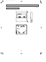
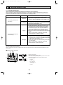
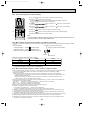
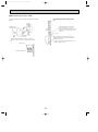
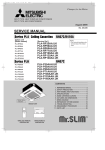
SPLIT-TYPE, HEAT PUMP AIR CONDITIONERS
February 2006
No. OC360
TECHNICAL & SERVICE MANUAL
Indoor unit
[Model names]
[Service Ref.]
PLH-3AAK
PLH-4AAK
PLH-5AAK
PLH-6AAK
PLH-3AAKH
PLH-4AAKH
PLH-5AAKH
PLH-6AAKH
PLH-3AAK
PLH-4AAK
PLH-5AAK
PLH-6AAK
PLH-3AAKH
PLH-4AAKH
PLH-5AAKH
PLH-6AAKH
NOTE:
• This manual does not
cover outdoor units.
When servicing outdoor
units, please refer to the
outdoor unit`s service
manual together with this
manual.
CONTENTS
Model name
indication
INDOOR UNIT
ON/OFF
TEMP
TEMP.
WIRELESS REMOTE
CONTROLLER
ON/OFF
WIRED REMOTE
CONTROLLER
1. REFERENCE MANUAL ······································2
2. PART NAMES AND FUNCTIONS ···················3
3. SPECIFICATIONS ············································6
4. DATA ······························································14
5. OUTLINES AND DIMENSIONS ·····················28
6. WIRING DIAGRAM ········································31
7. REFRIGERANT SYSTEM DIAGRAM ············32
8. TROUBLESHOOTING ···································34
9. FUNCTION SETTING·····································50
10. 4-WAY AIR FLOW SYSTEM ··························57
11. SYSTEM CONTROL ······································62
12. DISASSEMBLY PROCEDURE ······················76
13. PARTS LIST ···················································79
14. OPTIONAL PARTS ········································84
OC360--1.qxp
1
06.2.24 1:56 PM
Page 2
REFERENCE MANUAL
1-1. OUTDOOR UNIT’S SERVICE MANUAL
Service Ref.
Service Manual No.
PUH-3VKA2.TH-A
PUH-3YKA1.TH-A
PUH-4YKSA1.TH-A
PUH-5/6YKSA3.TH-A
PUH-3VKA.TH
PUH-3YKA.TH
PUH-4/5/6YKSA.TH
PUH-3NKA.TH
PUH-4/5/6TKSA.TH
OC156
OC325
OC354
2
OC360--1.qxp
06.2.24 1:56 PM
2
Page 3
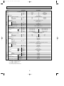
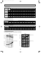
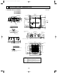
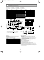
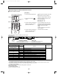
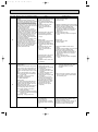
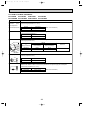
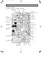
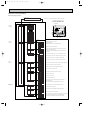
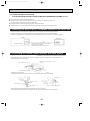
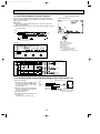
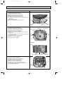
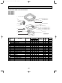
PART NAMES AND FUNCTIONS
● Indoor Unit
Filter
Removes dust and pollutants
from intake air
Horizontal Air Outlet
Sets airflow of horizontal automatically
during cooling or dehumidifying.
Grille
Auto Air Swing Vane
Disperses airflow up and
down and adjusts the angle
of airflow direction.
Air Intake
Intakes air from room.
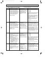
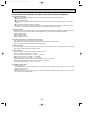
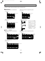
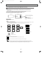
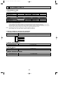
● Wired remote controller
On the controls are set, the same operation mode can be repeated by simply pressing the ON/OFF button.
● Operation buttons
ON/OFF button
Set Temperature buttons
Down
Fan Speed button
Up
Timer Menu button
(Monitor/Set button)
Filter
button
(<Enter> button)
Mode button (Return button)
TEMP.
ON/OFF
Set Time buttons
Check button (Clear button)
Back
Ahead
Test Run button
MENU
BACK
MONITOR/SET
ON/OFF
FILTER
DAY
CHECK TEST
Airflow Up/Down button
Timer On/Off button
(Set Day button)
PAR-21MAA
CLOCK
OPERATION
CLEAR
Louver button
Operation button)
(
To preceding operation
number.
Opening the
door.
Ventilation button
Operation button)
(
To next operation number.
3
OC360--1.qxp
06.2.24 1:56 PM
Page 4
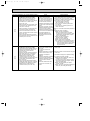
● Display
“Sensor” indication
Displayed when the remote controller
sensor is used.
Day-of-Week
For purposes of this explanation,
all parts of the display are shown
as lit. During actual operation, only
the relevant items will be lit.
Shows the current day of the week.
Time/Timer Display
“Locked” indicator
Shows the current time, unless the simple or Auto Off
timer is set.
If the simple or Auto Off timer is set, shows the time
remaining.
Indicates that remote controller buttons have been locked.
Identifies the current operation
“Clean The Filter” indicator
Shows the operating mode, etc.
* Multilanguage display is supported.
Comes on when it is time to clean the
filter.
TIME SUN MON TUE WED THU FRI SAT
TIMER
Hr
ON
AFTER
FUNCTION
FILTER
˚F˚C
“Centrally Controlled” indicator
Indicates that operation of the remote controller has been prohibited by a master controller.
Timer indicators
AFTER OFF
ERROR CODE
˚F˚C
The indicator comes on if the corresponding timer is set.
WEEKLY
SIMPLE
AUTO OFF
ONLY1Hr.
Fan Speed indicator
Shows the selected fan speed.
“Timer Is Off” indicator
Indicates that the timer is off.
Temperature Setting
Shows the target temperature.
Up/Down Air Direction indicator
Room Temperature display
Shows the room temperature.
The indicator
shows the direction of the outcoming airflow.
Louver display
“One Hour Only” indicator
Indicates the action of the swing
louver. Does not appear if the
louver is stationary.
Displayed if the airflow is set to
weak and downward during COOL
or DRY mode. (Operation varies
according to model.)
The indicator goes off after one
hour, at which time the airflow direction also changes.
Ventilation indicator
Appears when the unit is running in
Ventilation mode.
(Power On indicator)
Indicates that the power is on.
Caution
● Only the Power on indicator lights when the unit is stopped and power supplied to the unit.
● If you press a button for a feature that is not installed at the indoor unit, the remote controller will display the “Not Available”
message.
If you are using the remote controller to drive multiple indoor units, this message will appear only if he feature is not
present at the parent unit.
● When power is turned ON for the first time, it is normal that “PLEASE WAIT” is displayed on the room temperature indication (For max. 2minutes). Please wait until this “PLEASE WAIT” indication disappear then start the operation.
4
OC360--1.qxp
06.2.24 1:56 PM
Page 5
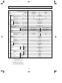
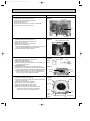
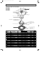
● Wireless remote controller
CHECK TEST RUN display
CHECK&TEST RUN display indicates that
the unit is being checked or test-run.
MODEL SELECT display
Blinks when model is selected.
display
Lights up while transmission to the indoor
unit is mode using switches.
display
SET TEMP. display indicates desired temperature set.
CLOCK display
display
Displays the current time.
OPERATION MODE display
Operation mode display indicates which operation mode is in effect.
TIMER display
CHECK TEST RUN
MODEL SELECT
˚C
AMPM
Displays when in timer operation or when
setting timer.
“
AMPM
NOT AVAILABLE
display
The vertical direction of air flow is indicated.
ON/OFF
“
TEMP
”“
” display
Displays the order of timer operation.
”“
” display
Displays whether timer is on or off.
display
button
FAN SPEED display indicates which fan
speed has been selected.
FAN
AUTO STOP
VANE
AUTO START
SET TEMPERATURE button sets any desired
room temperature.
ON/OFF button
The unit is turned ON and OFF alternately
each time the button is pressed.
MODE
CHECK LOUVER
h
FAN SPEED SELECT button
Used to change the fan speed.
MODE SELECT button
TEST RUN
SET
min
RESET
Used to switch the operation mode between
cooling, drying, blowing, heating and auto
mode.
TIMER CONTROL buttons
AUTO STOP (OFF timer): when this switch
is set, the air conditioner will be automatically stopped at the preset time.
AUTO START (ON timer): when this switch
is set, the air conditioner will be automatically started at the preset time.
CLOCK
h and min buttons
Buttons used to set the “hour and minute” of
the current time and timer settings.
w In case the outdoor unit is cool only type,
the heating mode is not available.
LOUVER button
CHECK-TEST RUN button
This switch the horizontal fan motion ON
and OFF.
Only press this button to perform an inspection check or test operation.
Do not use it for normal operation.
(Not available for this model.)
CLOCK button
VANE CONTROL button
RESET button
Used to change the air flow direction.
SET button
5
OC360--1.qxp
3
06.2.24 1:56 PM
Page 6
SPECIFICATIONS
Service Ref.
Item
PLH-3AAK(H)
Function
Capacity
Total input
Service Ref.
Power supply(phase, cycle,voltage)
Input
Running current
Starting current
External finish
Heat exchanger
Fan(drive) x No.
Fan
Fan motor output
Airflow(Low-High)
External static pressure
Booster heater
Operation control & Thermostat
Noise level(Low-High)
Unit drain pipe O.D.
PLH-3AAK(H)
Single, 50Hz, 220-240V
kW
A
A
INDOOR UNIT
OUTDOOR UNIT
Dimensions
REFRIGERANT
PIPING
kW
K/ min (CFM)
Pa
kW
W
D
H
Weight
Service Ref.
Power supply (phase, cycle, voltage)
Input
Running current
Starting current
External finish
Refrigerant control
Compressor
Model
Motor output
Starter type
Protection devices
Heat exchanger
Fan(drive) x No.
Fan
Fan motor output
Airflow
Defrost method
Noise level
Dimensions
dB
mm(in.)
mm(in.)
mm(in.)
mm(in.)
kg(lbs)
kW
A
A
kW
kW
K/ min (CFM)
W
D
H
Weight
Refrigerant
Charge
Oil<Model>
dB
mm(in.)
mm(in.)
mm(in.)
kg(lbs)
kg(lbs)
L
mm(in.)
mm(in.)
Liquid
Gas
Indoor side
Connection method
Outdoor side
Height difference
Between the indoor & outdoor units
Piping length
Pipe size O.D.
0.17
0.81
1.00
0.17[2.27]
0.81[9.47]
1.00[9.7]
Grille : Munsell 0.70Y 8.59/0.97
Plate fin coil
Turbo fan (direct) x 1
0.07
15-20(530-705)
0(direct blow)
[2.1]
Remote controller & built-in
28-34
32(1-1/4)
PANEL : 950(37-3/8)
UNIT : 840(33-1/6)
PANEL : 950(37-3/8)
UNIT : 840(33-1/6)
PANEL : 30(1-3/16)
UNIT : 258(10-1/8)
PANEL : 5(11)
UNIT : 24(53) [26(57)]
PUH-3VKA.TH, PUH-3VKA2.TH-A/PUH-3YKA.TH, PUH-3YKA1.TH-A
Single, 50Hz, 220-240V/3, 50Hz, 380-415V(4wires)
2.94
3.15
12.89/4.81
13.82/5.16
58/37
58/37
Munsell 5Y 7/1
Capillary tube
Hermetic
NH52VNHT/NH52YDAT
2.2/2.4
Line start
w1
Plate fin coil
Propeller (direct) x1
0.085
50(1764)
Reverse cycle
52
870(34-1/4)
295+24 (11-5/8 add 1)
850(33-1/4)
75(165)
R-22
3.2(7.1)
1.6<MS-32>
9.52 (3/8)
15.88(5/8)
Flared
Flared
Max. 50m
Max. 50m
w1 V …Internal Thermostat, HP switch
Y …Anti-phase protector, thermal relay, thermal switch, HP switch
Notes:
Heating
28,700[35,800]
8,400[10,500]
3.11[5.21]
Cooling
26,300
7,700
3.32
Btu/h
W
kW
Rating condition (ISO T1<JIS B8616>)
Cooling: Indoor : D.B. 27°C, W.B. 19°C
Outdoor : D.B. 35°C, W.B. 24°C
Heating: Indoor : D.B. 20°C
Outdoor : D.B. 7°C, W.B. 6°C
Refrigerant piping length(one way):5m(16ft)
6
OC360--1.qxp
06.2.24 1:56 PM
Page 7
Service Ref.
Item
PLH-3AAK
Btu/h
W
kW
Capacity
Total input
Service Ref.
Power supply(phase, cycle,voltage)
Input
Running current
Starting current
External finish
Heat exchanger
Fan
Fan(drive) x No.
Fan motor output
Airflow(Low-High)
External static pressure
Booster heater
Operation control & Thermostat
Noise level(Low-High)
Unit drain pipe O.D.
PLH-3AAK
Single, 60Hz, 220V
kW
A
A
INDOOR UNIT
OUTDOOR UNIT
Dimensions
REFRIGERANT
PIPING
0.16
0.77
1.00
dB
mm(in.)
mm(in.)
mm(in.)
mm(in.)
kg(lbs)
W
D
H
kW
A
A
kW
kW
K/ min (CFM)
W
D
H
Weight
Refrigerant
Charge
Oil<Model>
dB
mm(in.)
mm(in.)
mm(in.)
kg(lbs)
kg(lbs)
L
mm(in.)
mm(in.)
Liquid
Gas
Indoor side
Connection method
Outdoor side
Height difference
Between the indoor & outdoor units
Piping length
Pipe size O.D.
Notes :
0.16
0.77
1.00
Grille : Munsell 0.70Y 8.59/0.97
Plate fin coil
Turbo fan (direct) x 1
0.07
15-20(530-705)
0(direct blow)
—
Remote controller & built-in
28-34
32(1-1/4)
PANEL : 950(37-3/8)
UNIT : 840(33-1/6)
PANEL : 950(37-3/8)
UNIT : 840(33-1/6)
PANEL : 30(1-3/16)
UNIT : 258(10-1/8)
PANEL : 5(11)
UNIT : 24(53)
PUH-3NKA.TH
Single, 60Hz, 220V
3.33
4.13/3.52
15.6
18.77/16.49
80
80
Munsell 5Y 7/1
Capillary tube
Hermetic
NHJ47NADT
2.2
Line start
Internal thermostat, HP switch
Plate fin coil
Propeller (direct) x1
0.085
50(1764)
Reverse cycle
52
870(34-1/4)
295+24 (11-5/8 add 1)
850(33-1/4)
78(172)
R-22
3.2(7.1)
1.6<MS-32>
9.52 (3/8)
15.88(5/8)
Flared
Flared
Max. 50m
Max. 50m
kW
K/ min (CFM)
Pa
kW
Weight
Service Ref.
Power supply (phase, cycle, voltage)
Input
Running current
Starting current
External finish
Refrigerant control
Compressor
Model
Motor output
Starter type
Protection devices
Heat exchanger
Fan
Fan(drive) x No.
Fan motor output
Airflow
Defrost method
Noise level
Dimensions
Heating w1
31,700
9,300
3.49
Cooling w1/w2
23,200/27,300
6,800/8,000
4.29/3.68
Function
w1.Rating condition (SSA 385)
Cooling: Indoor : D.B. 29°C, W.B. 19°C
Outdoor: D.B. 46°C, W.B. 24°C
Heating: Indoor : D.B. 21°C
Outdoor: D.B. 7°C, W.B. 6°C
w2.Rating condition (ISO T1<JIS 8616>)
Cooling: Indoor : D.B. 27°C, W.B. 19°C
Outdoor: D.B. 35°C, W.B. 24°C
Refrigerant piping length(one way):5m(16ft)
7
OC360--1.qxp
06.2.24 1:56 PM
Page 8
Service Ref.
Item
PLH-4AAK(H)
Function
Capacity
Total input
Service Ref.
Power supply(phase, cycle,voltage)
Input
Running current
Starting current
External finish
Heat exchanger
Fan(drive) x No.
Fan
Fan motor output
Airflow(Low-High)
External static pressure
Booster heater
Operation control & Thermostat
Noise level(Low-High)
Unit drain pipe O.D.
kW
A
A
REFRIGERANT
PIPING
Notes:
kW
K/ min (CFM)
Pa
kW
W
D
H
Weight
Service Ref.
Power supply (phase, cycle, voltage)
Input
Running current
Starting current
External finish
Refrigerant control
Compressor
Model
Motor output
Starter type
Protection devices
Heat exchanger
Fan(drive) x No.
Fan
Fan motor output
Airflow
Defrost method
Noise level
Dimensions
Heating
35,500[44,400]
10,400[13,000]
3.45[6.05]
PLH-4AAK(H)
Single, 50Hz, 220-240V
INDOOR UNIT
OUTDOOR UNIT
Dimensions
Cooling
33,100
9,700
3.46
Btu/h
W
kW
dB
mm(in.)
mm(in.)
mm(in.)
mm(in.)
kg(lbs)
kW
A
A
kW
kW
K/ min (CFM)
W
D
H
Weight
Refrigerant
Charge
Oil<Model>
dB
mm(in.)
mm(in.)
mm(in.)
kg(lbs)
kg(lbs)
L
mm(in.)
mm(in.)
Liquid
Gas
Indoor side
Connection method
Outdoor side
Height difference
Between the indoor & outdoor units
Piping length
Pipe size O.D.
0.26
1.25
2.0
0.26[2.86]
1.25[11.93]
2.0[12.7]
Grille : Munsell 0.70Y 8.59/0.97
Plate fin coil
Turbo fan (direct) x 1
0.120
20-28(705-990)
0(direct blow)
[2.6]
Remote controller & built-in
33-41
32(1-1/4)
UNIT : 840(33-1/6)
PANEL : 950(37-3/8)
UNIT : 840(33-1/6)
PANEL : 950(37-3/8)
UNIT : 298(11-3/4)
PANEL : 30(1-3/16)
UNIT : 30(66)[32(71)]
PANEL : 5(11)
PUH-4YKSA.TH, PUH-4YKSA1.TH-A
3, 50Hz, 380V-415V(4wire)
3.20
3.19
5.24
5.22
40
40
Munsell 5Y 7/1
Capillary tube
Hermetic
NH56YDAT
2.7
Line start
Anti-phase protector, Thermal relay, Thermal switch, HP switch
Plate fin coil
Propeller (direct) x2
0.065+0.065
95(3550)
Reverse cycle
54
870(34-1/4)
295+24(11-5/8 add 1)
1258(49-1/2)
94(207)
R-22
4.2(9.2)
1.6<MS-32>
9.52(3/8)
19.05(3/4)
Flared
Flared
Max. 50m
Max. 50m
Rating condition (ISO T1<JIS B8616>)
Cooling: Indoor : D.B. 27°C, W.B. 19°C
Outdoor : D.B. 35°C, W.B. 24°C
Heating: Indoor : D.B. 20°C
Outdoor : D.B. 7°C, W.B. 6°C
Refrigerant piping length(one way):5m(16ft)
8
OC360--1.qxp
06.2.24 1:56 PM
Page 9
Service Ref.
Item
PLH-4AAK
Cooling w1/w2
33,800/37,400
9,900/10,950
5.26/4.93
Function
Btu/h
W
kW
Capacity
Total input
Service Ref.
Power supply(phase, cycle,voltage)
Input
Running current
Starting current
External finish
Heat exchanger
Fan(drive) x No.
Fan
Fan motor output
Airflow(Low-High)
External static pressure
Booster heater
Operation control & Thermostat
Noise level(Low-High)
Unit drain pipe O.D.
PLH-4AAK
Single, 60Hz, 220V
REFRIGERANT
PIPING
Notes:
dB
mm(in.)
mm(in.)
mm(in.)
mm(in.)
kg(lbs)
W
D
H
kW
A
A
kW
kW
K/ min (CFM)
W
D
H
Weight
Refrigerant
Charge
Oil<Model>
dB
mm(in.)
mm(in.)
mm(in.)
kg(lbs)
kg(lbs)
L
mm(in.)
mm(in.)
Liquid
Gas
Indoor side
Connection method
Outdoor side
Height difference
Between the indoor & outdoor units
Piping length
Pipe size O.D.
0.25
1.19
2.0
Grille : Munsell 0.70Y 8.59/0.97
Plate fin coil
Turbo fan (direct) x 1
0.120
20-28(705-990)
0(direct blow)
—
Remote controller & built-in
33-41
32(1-1/4)
UNIT : 840(33-1/6)
PANEL : 950(37-3/8)
UNIT : 840(33-1/6)
PANEL : 950(37-3/8)
UNIT : 298(11-3/4)
PANEL : 30(1-3/16)
UNIT : 30(66)
PANEL : 5(11)
PUH-4TKSA.TH
3, 60Hz, 220V
5.01/4.14
3.96
14.14/11.81
11.3
69
69
Munsell 5Y 7/1
Capillary tube
Hermetic
NHJ56TKAT
2.7
Line start
Anti-phase protector, Thermal relay, Thermal switch, HP switch
Plate fin coil
Propeller (direct) x2
0.065+0.065
95(3550)
Reverse cycle
55
870(34-1/4)
295+24(11-5/8 add 1)
1258(49-1/2)
94(207)
R-22
4.7(10.4)
1.6<MS-32>
9.52(3/8)
19.05(3/4)
Flared
Flared
Max. 50m
Max. 50m
kW
K/ min (CFM)
Pa
kW
Weight
Service Ref.
Power supply (phase, cycle, voltage)
Input
Running current
Starting current
External finish
Refrigerant control
Compressor
Model
Motor output
Starter type
Protection devices
Heat exchanger
Fan(drive) x No.
Fan
Fan motor output
Airflow
Defrost method
Noise level
Dimensions
0.25
1.19
2.0
kW
A
A
INDOOR UNIT
OUTDOOR UNIT
Dimensions
Heating w1
41,300
12,100
4.21
w1.Rating condition (SSA 385)
Cooling: Indoor : D.B. 29°C, W.B. 19°C
Outdoor: D.B. 46°C, W.B. 24°C
Heating: Indoor : D.B. 21°C
Outdoor: D.B. 7°C, W.B. 6°C
w2.Rating condition (ISO T1<JIS 8616>)
Cooling: Indoor : D.B. 27°C, W.B. 19°C
Outdoor: D.B. 35°C, W.B. 24°C
Refrigerant piping length(one way):5m(16ft)
9
OC360--1.qxp
06.2.24 1:56 PM
Page 10
Service Ref.
Item
PLH-5AAK(H)
Function
Capacity
Total input
Service Ref.
Power supply(phase, cycle,voltage)
Input
Running current
Starting current
External finish
Heat exchanger
Fan(drive) x No.
Fan
Fan motor output
Airflow(Low-High)
External static pressure
Booster heater
Operation control & Thermostat
Noise level(Low-High)
Unit drain pipe O.D.
kW
A
A
REFRIGERANT
PIPING
Notes:
kW
K/ min (CFM)
Pa
kW
W
D
H
Weight
Service Ref.
Power supply (phase, cycle, voltage)
Input
Running current
Starting current
External finish
Refrigerant control
Compressor
Model
Motor output
Starter type
Protection devices
Heat exchanger
Fan(drive) x No.
Fan
Fan motor output
Airflow
Defrost method
Noise level
Dimensions
Heating
47,800[58,000]
14,000[17,000]
4.46[7.46]
PLH-5AAK(H)
Single, 50Hz, 220-240V
INDOOR UNIT
OUTDOOR UNIT
Dimensions
Cooling
42,300
12,400
4.51
Btu/h
W
kW
dB
mm(in.)
mm(in.)
mm(in.)
mm(in.)
kg(lbs)
kW
A
A
kW
kW
K/ min (CFM)
W
D
H
Weight
Refrigerant
Charge
Oil<Model>
dB
mm(in.)
mm(in.)
mm(in.)
kg(lbs)
kg(lbs)
L
mm(in.)
mm(in.)
Liquid
Gas
Indoor side
Connection method
Outdoor side
Height difference
Between the indoor & outdoor units
Piping length
Pipe size O.D.
0.30
1.43
2.0
0.30[3.30]
1.43[13.77]
2.0[14.3]
Grille : Munsell 0.70Y 8.59/0.97
Plate fin coil
Turbo fan (direct) x 1
0.120
22-30(775-1,060)
0(direct blow)
[3.0]
Remote controller & built-in
35-43
32(1-1/4)
UNIT : 840(33-1/16)
PANEL : 950(37-3/8)
UNIT : 840(33-1/16)
PANEL : 950(37-3/8)
UNIT : 298(11-3/4)
PANEL : 30(1-3/16)
UNIT : 30(66) [32(71)]
PANEL : 5(11)
PUH-5YKSA.TH, PUH-5YKSA3.TH-A
3, 50Hz, 380-415V(4wire)
4.21
4.16
6.89
6.81
53
53
Munsell 5Y 7/1
Capillary tube
Hermetic
ZR61KC-TFD
3.5
Line start
Internal thermostat, Anti-phase protector, Thermal switch, HP switch
Plate fin coil
Propeller (direct) x2
0.085+0.085
95(3550)
Reverse cycle
55
970(38-3/16)
345+24(13-9/16 add 1)
1258(49-1/2)
114(251)
R-22
5.4(11.9)
2.130<SONTEX-200LT>
9.52(3/8)
19.05(3/4)
Flared
Flared
Max. 50m
Max. 50m
Rating condition (ISO T1<JIS B8616>)
Cooling: Indoor : D.B. 27°C, W.B. 19°C
Outdoor : D.B. 35°C, W.B. 24°C
Heating: Indoor : D.B. 20°C
Outdoor : D.B. 7°C, W.B. 6°C
Refrigerant piping length(one way):5m(16ft)
10
OC360--1.qxp
06.2.24 1:56 PM
Page 11
Service Ref.
Item
PLH-5AAK
Cooling w1/w2
37,500/44,400
11,000/13,000
6.78/5.58
Function
Btu/h
W
kW
Capacity
Total input
Service Ref.
Power supply(phase, cycle,voltage)
Input
Running current
Starting current
External finish
Heat exchanger
Fan(drive) x No.
Fan
Fan motor output
Airflow(Low-High)
External static pressure
Booster heater
Operation control & Thermostat
Noise level(Low-High)
Unit drain pipe O.D.
PLH-5AAK
Single, 60Hz, 220V
REFRIGERANT
PIPING
Notes:
dB
mm(in.)
mm(in.)
mm(in.)
mm(in.)
kg(lbs)
W
D
H
kW
A
A
kW
kW
K/ min (CFM)
W
D
H
Weight
Refrigerant
Charge
Oil<Model>
dB
mm(in.)
mm(in.)
mm(in.)
kg(lbs)
kg(lbs)
L
mm(in.)
mm(in.)
Liquid
Gas
Indoor side
Connection method
Outdoor side
Height difference
Between the indoor & outdoor units
Piping length
Pipe size O.D.
0.26
1.24
2.0
Grille : Munsell 0.70Y 8.59/0.97
Plate fin coil
Turbo fan (direct) x 1
0.120
22-30(775-1,060)
0(direct blow)
—
Remote controller & built-in
35-43
32(1-1/4)
UNIT : 840(33-1/16)
PANEL : 950(37-3/8)
UNIT : 840(33-1/16)
PANEL : 950(37-3/8)
UNIT : 298(11-3/4)
PANEL : 30(1-3/16)
UNIT : 30(66)
PANEL :5(11)
PUH-5TKSA.TH
3, 60Hz, 220V
6.52/5.32
5.76
19.23/16.23
17.38
135
135
Munsell 5Y 7/1
Capillary tube
Hermetic
ZR61KC-TF5
3.5
Line start
Internal thermostat, Anti-phase protector, Thermal switch, HP switch
Plate fin coil
Propeller (direct) x2
0.100+0.100
100(3500)
Reverse cycle
55
970(38-3/16)
345+24(13-9/16 add 1)
1258(49-1/2)
114(251)
R-22
5.4(11.9)
2.13<SONTEX-200LT>
9.52(3/8)
19.05(3/4)
Flared
Flared
Max. 50m
Max. 50m
kW
K/ min (CFM)
Pa
kW
Weight
Service Ref.
Power supply (phase, cycle, voltage)
Input
Running current
Starting current
External finish
Refrigerant control
Compressor
Model
Motor output
Starter type
Protection devices
Heat exchanger
Fan(drive) x No.
Fan
Fan motor output
Airflow
Defrost method
Noise level
Dimensions
0.26
1.24
2.0
kW
A
A
INDOOR UNIT
OUTDOOR UNIT
Dimensions
Heating w1
56,300
16,500
6.02
w1.Rating condition (SSA 385)
Cooling: Indoor : D.B. 29°C, W.B. 19°C
Outdoor: D.B. 46°C, W.B. 24°C
Heating: Indoor : D.B. 21°C
Outdoor: D.B. 7°C, W.B. 6°C
w2.Rating condition (ISO T1<JIS 8616>)
Cooling: Indoor : D.B. 27°C, W.B. 19°C
Outdoor: D.B. 35°C, W.B. 24°C
Refrigerant piping length(one way):5m(16ft)
11
OC360--1.qxp
06.2.24 1:56 PM
Page 12
Service Ref.
Item
PLH-6AAK(H)
Function
Capacity
Total input
Service Ref.
Power supply(phase, cycle,voltage)
Input
Running current
Starting current
External finish
Heat exchanger
Fan(drive) x No.
Fan
Fan motor output
Airflow(Low-High)
External static pressure
Booster heater
Operation control & Thermostat
Noise level(Low-High)
Unit drain pipe O.D.
kW
A
A
REFRIGERANT
PIPING
Notes:
kW
K/ min (CFM)
Pa
kW
W
D
H
Weight
Service Ref.
Power supply (phase, cycle, voltage)
Input
Running current
Starting current
External finish
Refrigerant control
Compressor
Model
Motor output
Starter type
Protection devices
Heat exchanger
Fan(drive) x No.
Fan
Fan motor output
Airflow
Defrost method
Noise level
Dimensions
Heating
54,900[65,200]
16,100[19,100]
4.92[7.92]
PLH-6AAK(H)
Single, 50Hz, 220-240V
INDOOR UNIT
OUTDOOR UNIT
Dimensions
Cooling
47,800
14,000
5.07
Btu/h
W
kW
dB
mm(in.)
mm(in.)
mm(in.)
mm(in.)
kg(lbs)
kW
A
A
kW
kW
K/ min (CFM)
W
D
H
Weight
Refrigerant
Charge
Oil<Model>
dB
mm(in.)
mm(in.)
mm(in.)
kg(lbs)
kg(lbs)
L
mm(in.)
mm(in.)
Liquid
Gas
Indoor side
Connection method
Outdoor side
Height difference
Between the indoor & outdoor units
Piping length
Pipe size O.D.
0.34
1.64
2.0
0.34[3.34]
1.64[13.94]
2.0[14.3]
Grille : Munsell 0.70Y 8.59/0.97
Plate fin coil
Turbo fan (direct) x 1
0.120
22-30(775-1,060)
0(direct blow)
[3.0]
Remote controller & built-in
37-45
32(1-1/4)
UNIT : 840(33-1/16)
PANEL : 950(37-3/8)
UNIT : 840(33-1/16)
PANEL : 950(37-3/8)
UNIT : 298(11-3/4)
PANEL : 30(1-3/16)
UNIT : 32(71)[34(75)]
PANEL : 5(11)
PUH-6YKSA.TH, PUH-6YKSA3.TH-A
3, 50Hz, 380-415V(4wire)
4.73
4.58
7.74
7.50
74
74
Munsell 5Y 7/1
Capillary tube
Hermetic
ZR68KC-TFD
4.0
Line start
Internal thermostat, Anti-phase protector, Thermal switch, HP switch
Plate fin coil
Propeller (direct) x2
0.10+0.10
100(3530)
Reverse cycle
56
970(38-3/16)
345+24(13-9/16 add 1)
1258(49-1/2)
117(258)
R-22
5.0(11.0)
1.774<SONTEX-200LT>
9.52(3/8)
19.05(3/4)
Flared
Flared
Max. 50m
Max. 50m
Rating condition (ISO T1<JIS B8616>)
Cooling: Indoor : D.B. 27°C, W.B. 19°C
Outdoor : D.B. 35°C, W.B. 24°C
Heating: Indoor : D.B. 20°C
Outdoor : D.B. 7°C, W.B. 6°C
Refrigerant piping length(one way):5m(16ft)
12
OC360--1.qxp
06.2.24 1:56 PM
Page 13
Service Ref.
Item
PLH-6AAK
Cooling w1/w2
45,700/51,900
13,400/15,200
7.32/6.15
Function
Btu/h
W
kW
Capacity
Total input
Service Ref.
Power supply(phase, cycle,voltage)
Input
Running current
Starting current
External finish
Heat exchanger
Fan(drive) x No.
Fan
Fan motor output
Airflow(Low-High)
External static pressure
Booster heater
Operation control & Thermostat
Noise level(Low-High)
Unit drain pipe O.D.
PLH-6AAK
Single, 60Hz, 220V
REFRIGERANT
PIPING
dB
mm(in.)
mm(in.)
mm(in.)
mm(in.)
kg(lbs)
W
D
H
kW
A
A
kW
kW
K/ min (CFM)
W
D
H
Weight
Refrigerant
Charge
Oil<Model>
dB
mm(in.)
mm(in.)
mm(in.)
kg(lbs)
kg(lbs)
L
mm(in.)
mm(in.)
Liquid
Gas
Indoor side
Connection method
Outdoor side
Height difference
Between the indoor & outdoor units
Piping length
Pipe size O.D.
Notes:
0.28
1.34
2.0
Grille : Munsell 0.70Y 8.59/0.97
Plate fin coil
Turbo fan (direct) x 1
0.120
22-30(775-1,060)
0(direct blow)
—
Remote controller & built-in
37-45
32(1-1/4)
UNIT : 840(33-1/16)
PANEL : 950(37-3/8)
UNIT : 840(33-1/16)
PANEL : 950(37-3/8)
UNIT : 298(11-3/4)
PANEL : 30(1-3/16)
UNIT : 32(71)
PANEL :5(11)
PUH-6TKSA.TH
3, 60Hz, 220V
7.04/5.87
6.42
20.3/17.31
18.51
140
140
Munsell 5Y 7/1
Capillary tube
Hermetic
ZR68KC-TF5
4.0
Line start
Internal thermostat, Anti-phase protector, Thermal switch, HP switch
Plate fin coil
Propeller (direct) x2
0.10+0.10
100(3530)
Reverse cycle
56
970(38-3/16)
345+24(13-9/16 add 1)
1258(49-1/2)
117(258)
R-22
5.0(11.0)
1.774<SONTEX-200LT>
9.52(3/8)
19.05(3/4)
Flared
Flared
Max. 50m
Max. 50m
kW
K/ min (CFM)
Pa
kW
Weight
Service Ref.
Power supply (phase, cycle, voltage)
Input
Running current
Starting current
External finish
Refrigerant control
Compressor
Model
Motor output
Starter type
Protection devices
Heat exchanger
Fan(drive) x No.
Fan
Fan motor output
Airflow
Defrost method
Noise level
Dimensions
0.28
1.34
2.0
kW
A
A
INDOOR UNIT
OUTDOOR UNIT
Dimensions
Heating w1
59,700
17,500
6.7
w1.Rating condition (SSA 385)
Cooling: Indoor : D.B. 29°C, W.B. 19°C
Outdoor: D.B. 46°C, W.B. 24°C
Heating: Indoor : D.B. 21°C
Outdoor: D.B. 7°C, W.B. 6°C
w2.Rating condition (ISO T1<JIS 8616>)
Cooling: Indoor : D.B. 27°C, W.B. 19°C
Outdoor: D.B. 35°C, W.B. 24°C
Refrigerant piping length(one way):5m(16ft)
13
OC360--1.qxp
06.2.24 1:56 PM
Page 14
DATA
4
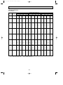
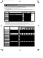
1. PERFORMANCE DATA [50Hz]
1) COOLING CAPACITY(1)
PLH-3AAK(H)
Indoor
Indoor
Intake air Intake air
D.B.(°C) W.B.(°C)
20
CA
SHC
SHF
P.C.
Outdoor intake air D.B.(°C)
25
CA
SHC
SHF
P.C.
30
CA
SHC
SHF
P.C.
20
16
7768
4972
0.64
2.66
7555
4835
0.64
2.77
7278
4658
0.64
2.99
20
18
8271
4301
0.52
2.71
8053
4188
0.52
2.83
7760
4035
0.52
3.06
22
16
7768
5593
0.72
2.66
7555
5440
0.72
2.77
7278
5240
0.72
2.99
22
18
8271
4963
0.60
2.71
8053
4832
0.60
2.83
7760
4656
0.60
3.06
22
20
8779
4214
0.48
2.77
8573
4115
0.48
2.89
8267
3968
0.48
3.12
24
16
7768
6214
0.80
2.66
7555
6044
0.80
2.77
7278
5822
0.80
2.99
24
18
8271
5624
0.68
2.71
8053
5476
0.68
2.83
7760
5277
0.68
3.06
24
20
8779
4916
0.56
2.77
8573
4801
0.56
2.89
8267
4630
0.56
3.12
24
22
9293
4089
0.44
2.82
9115
4011
0.44
2.94
8799
3872
0.44
3.19
26
16
7768
6836
0.88
2.66
7555
6649
0.88
2.77
7278
6404
0.88
2.99
26
18
8271
6286
0.76
2.71
8053
6120
0.76
2.83
7760
5898
0.76
3.06
26
20
8779
5619
0.64
2.77
8573
5487
0.64
2.89
8267
5291
0.64
3.12
26
22
9293
4832
0.52
2.82
9115
4740
0.52
2.94
8799
4576
0.52
3.19
27
16
7768
7147
0.92
2.66
7555
6951
0.92
2.77
7278
6696
0.92
2.99
27
18
8271
6617
0.80
2.71
8053
6443
0.80
2.83
7760
6208
0.80
3.06
27
20
8779
5970
0.68
2.77
8573
5830
0.68
2.89
8267
5622
0.64
3.12
27
22
9293
5204
0.56
2.82
9115
5104
0.56
2.94
8799
4928
0.52
3.19
28
16
7768
7457
0.96
2.66
7555
7253
0.96
2.77
7278
6987
0.96
2.99
28
18
8271
6948
0.84
2.71
8053
6765
0.84
2.83
7760
6518
0.84
3.06
28
20
8779
6321
0.72
2.77
8573
6173
0.72
2.89
8267
5952
0.72
3.12
28
22
9293
5576
0.60
2.82
9115
5469
0.60
2.94
8799
5279
0.60
3.19
30
16
7768
7768
1.00
2.66
7555
7555
1.00
2.77
7278
7278
1.00
2.99
30
18
8271
7609
0.92
2.71
8053
7409
0.92
2.83
7760
7139
0.92
3.06
30
20
8779
7023
0.80
2.77
8573
6858
0.80
2.89
8267
6614
0.80
3.12
30
22
9293
6319
0.68
2.82
9115
6198
0.68
2.94
8799
5983
0.68
3.19
32
16
7768
7768
1.00
2.66
7555
7555
1.00
2.77
7278
7278
1.00
2.99
32
18
8271
8271
1.00
2.71
8053
8053
1.00
2.83
7760
7760
1.00
3.06
32
20
8779
7726
0.88
2.77
8573
7544
0.88
2.89
8267
7275
0.88
3.12
32
22
9293
7063
0.76
2.82
9115
6927
0.76
2.94
8799
6687
0.76
3.19
CA : Capacity (W)
P.C. : Power consumption (kW)
SHC : Sensible heat capacity (W)
SHF : Sensible heat factor
14
OC360--1.qxp
06.2.24 1:56 PM
Page 15
COOLING CAPACITY(2)
PLH-3AAK(H)
Indoor
Indoor
Intake air Intake air
D.B.(°C) W.B.(°C)
35
CA
SHC
SHF
P.C.
Outdoor intake air D.B.(°C)
40
CA
SHC
SHF
P.C.
45
CA
SHC
SHF
P.C.
20
16
6983
4469
0.64
3.20
6671
4269
0.64
3.42
6342
4059
0.64
3.64
20
18
7452
3875
0.52
3.28
7130
3708
0.52
3.51
6793
3532
0.52
3.73
22
16
6983
5028
0.72
3.20
6671
4803
0.72
3.42
6342
4566
0.72
3.64
22
18
7452
4471
0.60
3.28
7130
4278
0.60
3.51
6793
4076
0.60
3.73
22
20
7948
3815
0.48
3.36
7616
3656
0.48
3.60
7270
3490
0.48
3.84
24
16
6983
5586
0.80
3.20
6671
5337
0.80
3.42
6342
5073
0.80
3.64
24
18
7452
5067
0.68
3.28
7130
4848
0.68
3.51
6793
4619
0.68
3.73
24
20
7948
4451
0.56
3.36
7616
4265
0.56
3.60
7270
4071
0.56
3.84
24
22
8470
3727
0.44
3.44
8128
3576
0.44
3.70
7773
3420
0.44
3.97
26
16
6983
6145
0.88
3.20
6671
5870
0.88
3.42
6342
5581
0.88
3.64
26
18
7452
5664
0.76
3.28
7130
5419
0.76
3.51
6793
5163
0.76
3.73
26
20
7948
5087
0.64
3.36
7616
4874
0.64
3.60
7270
4653
0.64
3.84
26
22
8470
4405
0.52
3.44
8128
4227
0.52
3.70
7773
4042
0.52
3.97
27
16
6983
6424
0.92
3.20
6671
6137
0.92
3.42
6342
5834
0.92
3.64
27
18
7452
5962
0.80
3.28
7130
5704
0.80
3.51
6793
5434
0.80
3.73
27
20
7948
5405
0.68
3.36
7616
5179
0.68
3.60
7270
4944
0.64
3.84
27
22
8470
4743
0.56
3.44
8128
4552
0.56
3.70
7773
4353
0.52
3.97
28
16
6983
6704
0.96
3.20
6671
6404
0.96
3.42
6342
6088
0.96
3.64
28
18
7452
6260
0.84
3.28
7130
5989
0.84
3.51
6793
5706
0.84
3.73
28
20
7948
5722
0.72
3.36
7616
5483
0.72
3.60
7270
5235
0.72
3.84
28
22
8470
5082
0.60
3.44
8128
4877
0.60
3.70
7773
4664
0.60
3.97
30
16
6983
6983
1.00
3.20
6671
6671
1.00
3.42
6342
6342
1.00
3.64
30
18
7452
6856
0.92
3.28
7130
6559
0.92
3.51
6793
6250
0.92
3.73
30
20
7948
6358
0.80
3.36
7616
6093
0.80
3.60
7270
5816
0.80
3.84
30
22
8470
5760
0.68
3.44
8128
5527
0.68
3.70
7773
5286
0.68
3.97
32
16
6983
6983
1.00
3.20
6671
6671
1.00
3.42
6342
6342
1.00
3.64
32
18
7452
7452
1.00
3.28
7130
7130
1.00
3.51
6793
6793
1.00
3.73
32
20
7948
6994
0.88
3.36
7616
6702
0.88
3.60
7270
6398
0.88
3.84
32
22
8470
6437
0.76
3.44
8128
6178
0.76
3.70
7773
5908
0.76
3.97
CA : Capacity (W)
P.C. : Power consumption (kW)
SHC : Sensible heat capacity (W)
SHF : Sensible heat factor
15
OC360--1.qxp
06.2.24 1:56 PM
Page 16
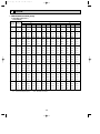
COOLING CAPACITY(3)
PLH-4AAK(H)
Indoor
Indoor
Intake air Intake air
D.B.(°C) W.B.(°C)
20
CA
SHC
SHF
P.C.
Outdoor intake air D.B.(°C)
25
CA
SHC
SHF
P.C.
30
CA
SHC
SHF
P.C.
20
16
9786
6752
0.69
2.77
9518
6567
0.69
2.89
9168
6326
0.69
3.11
20
18
10419
5939
0.57
2.83
10145
5783
0.57
2.95
9775
5572
0.57
3.18
22
16
9786
7535
0.77
2.77
9518
7329
0.77
2.89
9168
7059
0.77
3.11
22
18
10419
6773
0.65
2.83
10145
6594
0.65
2.95
9775
6354
0.65
3.18
22
20
11060
5862
0.53
2.88
10800
5724
0.53
3.01
10414
5520
0.53
3.25
24
16
9786
8318
0.85
2.77
9518
8090
0.85
2.89
9168
7793
0.85
3.11
24
18
10419
7606
0.73
2.83
10145
7406
0.73
2.95
9775
7136
0.73
3.18
24
20
11060
6746
0.61
2.88
10800
6588
0.61
3.01
10414
6353
0.61
3.25
24
22
11707
5736
0.49
2.94
11482
5626
0.49
3.07
11085
5431
0.49
3.32
26
16
9786
9101
0.93
2.77
9518
8852
0.93
2.89
9168
8526
0.93
3.11
26
18
10419
8440
0.81
2.83
10145
8217
0.81
2.95
9775
7918
0.81
3.18
26
20
11060
7631
0.69
2.88
10800
7452
0.69
3.01
10414
7186
0.69
3.25
26
22
11707
6673
0.57
2.94
11482
6545
0.57
3.07
11085
6318
0.57
3.32
27
16
9786
9492
0.97
2.77
9518
9232
0.97
2.89
9168
8893
0.97
3.11
27
18
10419
8856
0.85
2.83
10145
8623
0.85
2.95
9775
8309
0.85
3.18
27
20
11060
8073
0.73
2.88
10800
7884
0.73
3.01
10414
7602
0.73
3.25
27
22
11707
7141
0.61
2.94
11482
7004
0.61
3.07
11085
6762
0.61
3.32
28
16
9786
9786
1.00
2.77
9518
9518
1.00
2.89
9168
9168
1.00
3.11
28
18
10419
9273
0.89
2.83
10145
9029
0.89
2.95
9775
8700
0.89
3.18
28
20
11060
8516
0.77
2.88
10800
8316
0.77
3.01
10414
8019
0.77
3.25
28
22
11707
7609
0.65
2.94
11482
7464
0.65
3.07
11085
7205
0.65
3.32
30
16
9786
9786
1.00
2.77
9518
9518
1.00
2.89
9168
.9168
1.00
3.11
30
18
10419
10107
0.97
2.83
10145
9841
0.97
2.95
9775
9482
0.97
3.18
30
20
11060
9401
0.85
2.88
10800
9180
0.85
3.01
10414
8852
0.85
3.25
30
22
11707
8546
0.73
2.94
11482
8382
0.73
3.07
11085
8092
0.73
3.32
32
16
9786
9786
1.00
2.77
9518
9518
1.00
2.89
9168
9168
1.00
3.11
32
18
10419
10419
1.00
2.83
10145
10145
1.00
2.95
9775
9775
1.00
3.18
32
20
11060
10285
0.93
2.88
10800
10044
0.93
3.01
10414
9685
0.93
3.25
32
22
11707
9483
0.81
2.94
11482
9301
0.81
3.07
11085
8979
0.81
3.32
CA : Capacity (W)
P.C. : Power consumption (kW)
SHC : Sensible heat capacity (W)
SHF : Sensible heat factor
16
OC360--1.qxp
06.2.24 1:56 PM
Page 17
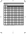
COOLING CAPACITY(4)
PLH-4AAK(H)
Indoor
Indoor
Intake air Intake air
D.B.(°C) W.B.(°C)
35
CA
SHC
SHF
P.C.
Outdoor intake air D.B.(°C)
40
CA
SHC
SHF
P.C.
45
CA
SHC
SHF
P.C.
20
16
8797
6070
0.69
3.34
8404
5798
0.69
3.56
7989
5512
0.69
3.79
20
18
9388
5351
0.57
3.42
8982
5120
0.57
3.65
8558
4878
0.57
3.89
22
16
8797
6773
0.77
3.34
8404
6471
0.77
3.56
7989
6151
0.77
3.79
22
18
9388
6102
0.65
3.42
8982
5838
0.65
3.65
8558
5562
0.65
3.89
22
20
10012
5307
0.53
3.50
9594
5085
0.53
3.75
9159
4854
0.53
4.00
24
16
8797
7477
0.85
3.34
8404
7143
0.85
3.56
7989
6790
0.85
3.79
24
18
9388
6853
0.73
3.42
8982
6557
0.73
3.65
8558
6247
0.73
3.89
24
20
10012
6107
0.61
3.50
9594
5852
0.61
3.75
9159
5587
0.61
4.00
24
22
10670
5228
0.49
3.59
10240
5017
0.49
3.86
9792
4798
0.49
4.14
26
16
8797
8181
0.93
3.34
8404
7815
0.93
3.56
7989
7430
0.93
3.79
26
18
9388
7604
0.81
3.42
8982
7275
0.81
3.65
8558
6932
0.81
3.89
26
20
10012
6908
0.69
3.50
9594
6620
0.69
3.75
9159
6320
0.69
4.00
26
22
10670
6082
0.57
3.59
10240
5837
0.57
3.86
9792
5582
0.57
4.14
27
16
8797
8533
0.97
3.34
8404
8151
0.97
3.56
7989
7749
0.97
3.79
27
18
9388
7980
0.85
3.42
8982
7634
0.85
3.65
8558
7274
0.85
3.89
27
20
10012
7309
0.73
3.50
9594
7003
0.73
3.75
9159
6686
0.73
4.00
27
22
10670
6509
0.61
3.59
10240
6246
0.61
3.86
9792
5973
0.61
4.14
28
16
8797
8797
1.00
3.34
8404
8404
1.00
3.56
7989
7989
1.00
3.79
28
18
9388
8355
0.89
3.42
8982
7994
0.89
3.65
8558
7616
0.89
3.89
28
20
10012
7709
0.77
3.50
9594
7387
0.77
3.75
9159
7052
0.77
4.00
28
22
10670
6936
0.65
3.59
10240
6656
0.65
3.86
9792
6365
0.65
4.14
30
16
8797
8797
1.00
3.34
8404
8404
1.00
3.56
7989
7989
1.00
3.79
30
18
9388
9106
0.97
3.42
8982
8712
0.97
3.65
8558
8301
0.97
3.89
30
20
10012
8510
0.85
3.50
9594
8155
0.85
3.75
9159
7785
0.85
4.00
30
22
10670
7789
0.73
3.59
10240
7475
0.73
3.86
9792
7148
0.73
4.14
32
16
8797
8797
1.00
3.34
8404
8404
1.00
3.56
7989
7989
1.00
3.79
32
18
9388
9388
1.00
3.42
8982
8982
1.00
3.65
8558
8558
1.00
3.89
32
20
10012
9311
0.93
3.50
9594
8922
0.93
3.75
9159
8518
0.93
4.00
32
22
10670
8643
0.81
3.59
10240
8294
0.81
3.86
9792
7932
0.81
4.14
CA : Capacity (W)
P.C. : Power consumption (kW)
SHC : Sensible heat capacity (W)
SHF : Sensible heat factor
17
OC360--1.qxp
06.2.24 1:56 PM
Page 18
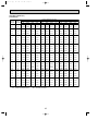
COOLING CAPACITY(5)
PLH-5AAK(H)
Indoor
Indoor
Intake air Intake air
D.B.(°C) W.B.(°C)
20
CA
SHC
SHF
P.C.
Outdoor intake air D.B.(°C)
25
CA
SHC
SHF
P.C.
30
CA
SHC
SHF
P.C.
20
16
12510
7881
0.63
3.61
12167
7665
0.63
3.77
11720
7384
0.63
4.06
20
18
13319
6793
0.51
3.69
12969
6614
0.51
3.85
12496
6373
0.51
4.15
22
16
12510
8882
0.71
3.61
12167
8639
0.71
3.77
11720
8321
0.71
4.06
22
18
13319
7858
0.59
3.69
12969
7652
0.59
3.85
12496
7373
0.59
4.15
22
20
14138
6645
0.47
3.76
13806
6489
0.47
3.92
13313
6257
0.47
4.24
24
16
12510
9883
0.79
3.61
12167
9612
0.79
3.77
11720
9259
0.79
4.06
24
18
13319
8924
0.67
3.69
12969
8689
0.67
3.85
12496
8373
0.67
4.15
24
20
14138
7776
0.55
3.76
13806
7593
0.55
3.92
13313
7322
0.55
4.24
24
22
14965
6435
0.43
3.83
14679
6312
0.43
4.00
14170
6093
0.43
4.33
26
16
12510
10883
0.87
3.61
12167
10585
0.87
3.77
11720
10196
0.87
4.06
26
18
13319
9990
0.75
3.69
12969
9727
0.75
3.85
12496
9372
0.75
4.15
26
20
14138
8907
0.63
3.76
13806
8698
0.63
3.92
13313
8387
0.63
4.24
26
22
14965
7632
0.51
3.83
14679
7486
0.51
4.00
14170
7227
0.51
4.33
27
16
12510
11384
0.91
3.61
12167
11072
0.91
3.77
11720
10665
0.91
4.06
27
18
13319
10522
0.79
3.69
12969
10245
0.79
3.85
12496
9872
0.79
4.15
27
20
14138
9472
0.67
3.76
13806
9250
0.67
3.92
13313
8920
0.67
4.24
27
22
14965
8231
0.55
3.83
14679
8073
0.55
4.00
14170
7794
0.55
4.33
28
16
12510
11884
0.95
3.61
12167
11559
0.95
3.77
11720
11134
0.95
4.06
28
18
13319
11055
0.83
3.69
12969
10764
0.83
3.85
12496
10372
0.83
4.15
28
20
14138
10038
0.71
3.76
13806
9802
0.71
3.92
13313
9452
0.71
4.24
28
22
14965
8830
0.59
3.83
14679
8660
0.59
4.00
14170
8360
0.59
4.33
30
16
12510
12510
1.00
3.61
12167
12167
1.00
3.77
11720
11720
1.00
4.06
30
18
13319
12121
0.91
3.69
12969
11802
0.91
3.85
12496
11372
0.91
4.15
30
20
14138
11169
0.79
3.76
13806
10907
0.79
3.92
13313
10517
0.79
4.24
30
22
14965
10027
0.67
3.83
14679
9835
0.67
4.00
14170
9494
0.67
4.33
32
16
12510
12510
1.00
3.61
12167
12167
1.00
3.77
11720
11720
1.00
4.06
32
18
13319
13186
0.99
3.69
12969
12839
0.99
3.85
12496
12371
0.99
4.15
32
20
14138
12300
0.87
3.76
13806
12011
0.87
3.92
13313
11582
0.87
4.24
32
22
14965
11224
0.75
3.83
14679
11009
0.75
4.00
14170
10628
0.75
4.33
CA : Capacity (W)
P.C. : Power consumption (kW)
SHC : Sensible heat capacity (W)
SHF : Sensible heat factor
18
OC360--1.qxp
06.2.24 1:56 PM
Page 19
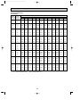
COOLING CAPACITY(6)
PLH-5AAK(H)
Indoor
Indoor
Intake air Intake air
D.B.(°C) W.B.(°C)
35
CA
SHC
SHF
P.C.
Outdoor intake air D.B.(°C)
40
CA
SHC
SHF
P.C.
45
CA
SHC
SHF
P.C.
20
16
11245
7085
0.63
4.35
10743
6768
0.63
4.64
10212
6434
0.63
4.94
20
18
12001
6120
0.51
4.46
11482
5856
0.51
4.76
10939
5579
0.51
5.07
22
16
11245
7984
0.71
4.35
10743
7627
0.71
4.64
10212
7251
0.71
4.94
22
18
12001
7080
0.59
4.46
11482
6774
0.59
4.76
10939
6454
0.59
5.07
22
20
12799
6016
0.47
4.56
12264
5764
0.47
4.89
11708
5503
0.47
5.22
24
16
11245
8884
0.79
4.35
10743
8487
0.79
4.64
10212
8068
0.79
4.94
24
18
12001
8041
0.67
4.46
11482
7693
0.67
4.76
10939
7329
0.67
5.07
24
20
12799
7040
0.55
4.56
12264
6745
0.55
4.89
11708
6439
0.55
5.22
24
22
13640
5865
0.43
4.67
13090
5629
0.43
5.03
12518
5383
0.43
5.39
26
16
11245
9783
0.87
4.35
10743
9346
0.87
4.64
10212
8885
0.87
4.94
26
18
12001
9001
0.75
4.46
11482
8611
0.75
4.76
10939
8205
0.75
5.07
26
20
12799
8064
0.63
4.56
12264
7726
0.63
4.89
11708
7376
0.63
5.22
26
22
13640
6957
0.51
4.67
13090
6676
0.51
5.03
12518
6384
0.51
5.39
27
16
11245
10233
0.91
4.35
10743
9776
0.91
4.64
10212
9293
0.91
4.94
27
18
12001
9481
0.79
4.46
11482
9071
0.79
4.76
10939
8642
0.79
5.07
27
20
12799
8575
0.67
4.56
12264
8217
0.67
4.89
11708
7844
0.67
5.22
27
22
13640
7502
0.55
4.67
13090
7199
0.55
5.03
12518
6885
0.55
5.39
28
16
11245
10683
0.95
4.35
10743
10206
0.95
4.64
10212
9702
0.95
4.94
28
18
12001
9961
0.83
4.46
11482
9530
0.83
4.76
10939
9080
0.83
5.07
28
20
12799
9087
0.71
4.56
12264
8708
0.71
4.89
11708
8313
0.71
5.22
28
22
13640
8048
0.59
4.67
13090
7723
0.59
5.03
12518
7386
0.59
5.39
30
16
11245
11245
1.00
4.35
10743
10743
1.00
4.64
10212
10212
1.00
4.94
30
18
12001
10921
0.91
4.46
11482
10448
0.91
4.76
10939
9955
0.91
5.07
30
20
12799
10111
0.79
4.56
12264
9689
0.79
4.89
11708
9249
0.79
5.22
30
22
13640
9139
0.67
4.67
13090
8770
0.67
5.03
12518
8387
0.67
5.39
32
16
11245
11245
1.00
4.35
10743
10743
1.00
4.64
10212
10212
1.00
4.94
32
18
12001
11881
0.99
4.46
11482
11367
0.99
4.76
10939
10830
0.99
5.07
32
20
12799
11135
0.87
4.56
12264
10670
0.87
4.89
11708
10186
0.87
5.22
32
22
13640
10230
0.75
4.67
13090
9817
0.75
5.03
12518
9389
0.75
5.39
CA : Capacity (W)
P.C. : Power consumption (kW)
SHC : Sensible heat capacity (W)
SHF : Sensible heat factor
19
OC360--1.qxp
06.2.24 1:56 PM
Page 20
COOLING CAPACITY(7)
PLH-6AAK(H)
Indoor
Indoor
Intake air Intake air
D.B.(°C) W.B.(°C)
20
CA
SHC
SHF
P.C.
Outdoor intake air D.B.(°C)
25
CA
SHC
SHF
P.C.
30
CA
SHC
SHF
P.C.
20
16
14124
8616
0.61
4.06
13737
8380
0.61
4.24
13232
8072
0.61
4.56
20
18
15038
7369
0.49
4.15
14642
7175
0.49
4.32
14109
6913
0.49
4.67
22
16
14124
9745
0.69
4.06
13737
9479
0.69
4.24
13232
9130
0.69
4.56
22
18
15038
8572
0.57
4.15
14642
8346
0.57
4.32
14109
8042
0.57
4.67
22
20
15962
7183
0.45
4.22
15587
7014
0.45
4.41
15031
6764
0.45
4.77
24
16
14124
10875
0.77
4.06
13737
10578
0.77
4.24
13232
10189
0.77
4.56
24
18
15038
9775
0.65
4.15
14642
9517
0.65
4.32
14109
9171
0.65
4.67
24
20
15962
8460
0.53
4.22
15587
8261
0.53
4.41
15031
7966
0.53
4.77
24
22
16896
6928
0.41
4.30
16573
6795
0.41
4.50
15998
6559
0.41
4.87
26
16
14124
12005
0.85
4.06
13737
11677
0.85
4.24
13232
11247
0.85
4.56
26
18
15038
10978
0.73
4.15
14642
10689
0.73
4.32
14109
10299
0.73
4.67
26
20
15962
9737
0.61
4.22
15587
9508
0.61
4.41
15031
9169
0.61
4.77
26
22
16896
8279
0.49
4.30
16573
8121
0.49
4.50
15998
7839
0.49
4.87
27
16
14124
12570
0.89
4.06
13737
12226
0.89
4.24
13232
11777
0.89
4.56
27
18
15038
11579
0.77
4.15
14642
11274
0.77
4.32
14109
10864
0.77
4.67
27
20
15962
10375
0.65
4.22
15587
10132
0.65
4.41
15031
9770
0.65
4.77
27
22
16896
8955
0.53
4.30
16573
8783
0.53
4.50
15998
8479
0.53
4.87
28
16
14124
13135
0.93
4.06
13737
12776
0.93
4.24
13232
12306
0.93
4.56
28
18
15038
12181
0.81
4.15
14642
11860
0.81
4.32
14109
11428
0.81
4.67
28
20
15962
11014
0.69
4.22
15587
10755
0.69
4.41
15031
10371
0.69
4.77
28
22
16896
9631
0.57
4.30
16573
9446
0.57
4.50
15998
9119
0.57
4.87
30
16
14124
14124
1.00
4.06
13737
13737
1.00
4.24
13232
13232
1.00
4.56
30
18
15038
13384
0.89
4.15
14642
13031
0.89
4.32
14109
12557
0.89
4.67
30
20
15962
12291
0.77
4.22
15587
12002
0.77
4.41
15031
11574
0.77
4.77
30
22
16896
10983
0.65
4.30
16573
10772
0.65
4.50
15998
10399
0.65
4.87
32
16
14124
14124
1.00
4.06
13737
13737
1.00
4.24
13232
13232
1.00
4.56
32
18
15038
14587
0.97
4.15
14642
14203
0.97
4.32
14109
13686
0.97
4.67
32
20
15962
13568
0.85
4.22
15587
13249
0.85
4.41
15031
12776
0.85
4.77
32
22
16896
12334
0.73
4.30
16573
12098
0.73
4.50
15998
11679
0.73
4.87
CA : Capacity (W)
P.C. : Power consumption (kW)
SHC : Sensible heat capacity (W)
SHF : Sensible heat factor
20
OC360--1.qxp
06.2.24 1:56 PM
Page 21
COOLING CAPACITY(8)
PLH-6AAK(H)
Indoor
Indoor
Intake air Intake air
D.B.(°C) W.B.(°C)
35
CA
SHC
SHF
P.C.
Outdoor intake air D.B.(°C)
40
CA
SHC
SHF
P.C.
45
CA
SHC
SHF
P.C.
20
16
12696
7745
0.61
4.89
12129
7399
0.61
5.22
11530
7033
0.61
5.55
20
18
13549
6639
0.49
5.01
12963
6352
0.49
5.35
12351
6052
0.49
5.70
22
16
12696
8760
0.69
4.89
12129
8369
0.69
5.22
11530
7956
0.69
5.55
22
18
13549
7723
0.57
5.01
12963
7389
0.57
5.35
12351
7040
0.57
5.70
22
20
14451
6503
0.45
5.13
13847
6231
0.45
5.50
13219
5948
0.45
5.87
24
16
12696
9776
0.77
4.89
12129
9339
0.77
5.22
11530
8878
0.77
5.55
24
18
13549
8807
0.65
5.01
12963
8426
0.65
5.35
12351
8028
0.65
5.70
24
20
14451
7659
0.53
5.13
13847
7339
0.53
5.50
13219
7006
0.53
5.87
24
22
15401
6314
0.41
5.25
14779
6059
0.41
5.65
14133
5795
0.41
6.06
26
16
12696
10792
0.85
4.89
12129
10310
0.85
5.22
11530
9801
0.85
5.55
26
18
13549
9891
0.73
5.01
12963
9463
0.73
5.35
12351
9016
0.73
5.70
26
20
14451
8815
0.61
5.13
13847
8446
0.61
5.50
13219
8063
0.61
5.87
26
22
15401
7546
0.49
5.25
14779
7242
0.49
5.65
14133
6925
0.49
6.06
27
16
12696
11300
0.89
4.89
12129
10795
0.89
5.22
11530
10262
0.89
5.55
27
18
13549
10433
0.77
5.01
12963
9982
0.77
5.35
12351
9510
0.77
5.70
27
20
14451
9393
0.65
5.13
13847
9000
0.65
5.50
13219
8592
0.65
5.87
27
22
15401
8162
0.53
5.25
14779
7833
0.53
5.65
14133
7491
0.53
6.06
28
16
12696
11808
0.93
4.89
12129
11280
0.93
5.22
11530
10723
0.93
5.55
28
18
13549
10975
0.81
5.01
12963
10500
0.81
5.35
12351
10004
0.81
5.70
28
20
14451
9971
0.69
5.13
13847
9554
0.69
5.50
13219
9121
0.69
5.87
28
22
15401
8778
0.57
5.25
14779
8424
0.57
5.65
14133
8056
0.57
6.06
30
16
12696
12696
1.00
4.89
12129
12129
1.00
5.22
11530
11530
1.00
5.55
30
18
13549
12059
0.89
5.01
12963
11537
0.89
5.35
12351
10992
0.89
5.70
30
20
14451
11127
0.77
5.13
13847
10662
0.77
5.50
13219
10178
0.77
5.87
30
22
15401
10010
0.65
5.25
14779
9606
0.65
5.65
14133
9187
0.65
6.06
32
16
12696
12696
1.00
4.89
12129
12129
1.00
5.22
11530
11530
1.00
5.55
32
18
13549
13143
0.97
5.01
12963
12574
0.97
5.35
12351
11981
0.97
5.70
32
20
14451
12283
0.85
5.13
13847
11770
0.85
5.50
13219
11236
0.85
5.87
32
22
15401
11242
0.73
5.25
14779
10789
0.73
5.65
14133
10317
0.73
6.06
CA : Capacity (W)
P.C. : Power consumption (kW)
SHC : Sensible heat capacity (W)
SHF : Sensible heat factor
21
OC360--1.qxp
06.2.24 1:56 PM
Page 22
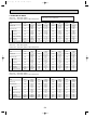
2) HEATING CAPACITY
Service Ref.
PLH-3AAK(H)
PLH-4AAK(H)
PLH-5AAK(H)
PLH-6AAK(H)
Indoor
intake air
D.B.(°C)
15
20
25
15
20
25
15
20
25
15
20
25
-10
-5
P.C.
2.12
2.29
2.43
2.35
2.54
2.69
2.35
2.54
2.69
3.36
3.62
3.84
CA
5752
5508
5293
7122
6820
6554
9587
9180
8822
11026
10557
10146
CA
6593
6334
6077
8163
7842
7524
10988
10557
10128
12636
12140
11647
P.C.
2.34
2.53
2.69
2.60
2.80
2.99
2.60
2.80
2.99
3.71
4.00
4.26
Outdoor intake air W.B.(°C)
0
5
P.C.
CA
P.C.
CA
2.83
8516
2.58
7514
3.05
8198
2.78
7231
3.27
7895
2.97
6944
3.14
10543
2.86
9303
3.39
10150
3.09
8953
3.63
9774
3.30
8597
3.14
10543
2.86
9303
3.39
10150
3.09
8953
3.63
9774
3.30
8597
4.48
16322
4.09
14402
4.83
15713
4.40
13859
5.17
15131
4.71
13309
10
CA
9595
9235
8928
11880
11434
11054
11880
11434
11054
18391
17700
17112
15
P.C.
3.10
3.34
3.58
3.44
3.70
3.97
3.44
3.70
3.97
4.90
5.28
5.66
P.C.
3.38
3.64
3.90
3.75
4.04
4.33
3.75
4.04
4.33
5.35
5.76
6.18
CA
10752
10340
10044
13312
12802
12435
13312
12802
12435
20608
19818
19250
Note C A :Capacity (W)
P.C.:Power consumption (kW)
Cooling capacity correction factors
Service Ref.
PLH-3AAK(H)
PLH-4AAK(H)
PLH-5AAK(H)
PLH-6AAK(H)
5m
1.00
1.00
1.00
1.00
10m
0.981
0.989
0.981
0.975
15m
0.968
0.980
0.968
0.955
Refrigerant piping length(one way)
35m
30m
25m
20m
0.913
0.925
0.940
0.952
0.940
0.950
0.960
0.970
0.913
0.925
0.940
0.952
0.884
0.900
0.918
0.935
40m
0.900
0.930
0.900
0.869
45m
0.886
0.920
0.886
0.855
50m
0.874
0.910
0.874
0.840
Refrigerant piping length(one way)
35m
30m
25m
0.998
1.00
1.00
0.998
1.00
1.00
0.998
1.00
1.00
0.998
1.00
1.00
40m
0.995
0.995
0.995
0.995
45m
0.993
0.993
0.993
0.993
50m
0.990
0.990
0.990
0.990
Heating capacity correction factors
Service Ref.
PLH-3AAK(H)
PLH-4AAK(H)
PLH-5AAK(H)
PLH-6AAK(H)
5m
1.00
1.00
1.00
1.00
15m
1.00
1.00
1.00
1.00
10m
1.00
1.00
1.00
1.00
20m
1.00
1.00
1.00
1.00
2. PERFORMANCE CURVE
PLH-3AAK(H) / PLH-4AAK(H) / PLH-5AAK(H) / PLH-6AAK(H)
Cooling
Heating
1.4
1.2
1.0
22
20
18
16
0.8
1.0
0.8
1.4
22
20
18
16
1.2
1.0
0.8
0.6
0.4
-5
15
20
25 INDOOR DB (°C)
1.2
0.6
0.6
1.4
TOTAL INPUT (RATIO)
CAPACITY (RATIO)
INDOOR WB(°C)
5
15
25 35 46
OUTDOOR DB(°C)
INDOOR WB(°C)
TOTAL INPUT (RATIO)
CAPACITY (RATIO)
1.4
25
20
15
1.2
1.0
0.8
0.6
0.4
-12-10
22
-5
0
5
10 15
OUTDOOR WB(°C)
INDOOR DB (°C)
OC360--1.qxp
06.2.24 1:56 PM
Page 23
3. PERFORMANCE DATA [60Hz]
1) COOLING CAPACITY(1)
PLH-3AAK / PLH-4AAK / PLH-5AAK / PLH-6AAK
Outdoor intake air D.B.(°C)
Indoor
Service Ref.
PLH-3AAK
PLH-4AAK
PLH-5AAK
PLH-6AAK
intake air
20
25
30
35
40
45
W.B.(°C)
CA
P.C.
CA
P.C.
CA
P.C.
CA
P.C.
CA
P.C.
CA
P.C.
16
8071
2.95
7850
3.08
7561
3.31
7255
3.55
6931
3.79
6589
4.03
18
8593
3.01
8367
3.14
8062
3.39
7742
3.64
7408
3.89
7058
4.14
20
9121
3.07
8907
3.20
8589
3.46
8258
3.72
7912
3.99
7554
4.26
22
9655
3.12
9470
3.26
9142
3.53
8800
3.81
8445
4.10
8076
4.40
16
11047
3.52
10744
3.67
10350
3.95
9930
4.23
9486
4.52
9018
4.81
18
11762
3.59
11452
3.74
11035
4.04
10597
4.34
10139
4.64
9660
4.93
20
12485
3.66
12191
3.82
11756
4.13
11303
4.44
10830
4.76
10339
5.08
22
13215
3.73
12962
3.89
12513
4.22
12045
4.55
11559
4.89
11054
5.25
16
13115
4.47
12756
4.66
12287
5.02
11789
5.38
11263
5.74
10707
6.11
18
13964
4.56
13596
4.76
13101
5.14
12581
5.51
12037
5.89
11469
6.27
20
14822
6.65
14474
4.85
13957
5.25
13419
5.65
12858
6.05
12275
6.46
22
15690
4.74
15389
4.95
14856
5.36
14301
5.78
13723
6.22
13124
6.67
16
15334
4.93
14915
5.14
14367
5.53
13785
5.93
13168
6.33
12518
6.73
18
16327
5.03
15897
5.24
15318
5.66
14711
6.08
14074
6.49
13410
6.91
20
17330
5.12
16923
5.35
16319
5.78
15689
6.22
15034
6.67
14352
7.12
22
18345
5.22
17993
5.45
17370
5.91
16721
6.37
16046
6.86
15345
7.35
Note C A :Capacity (W)
P.C.:Power consumption (kW)
Cooling capacity correction factors
Service Ref.
PLH-3AAK
PLH-4AAK
PLH-5AAK
PLH-6AAK
5m
1.00
1.00
1.00
1.00
10m
0.981
0.989
0.981
0.975
Refrigerant piping length(one way)
35m
30m
25m
20m
0.913
0.925
0.940
0.952
0.940
0.950
0.960
0.970
0.913
0.925
0.940
0.952
0.884
0.900
0.918
0.935
15m
0.968
0.980
0.968
0.955
45m
0.886
0.920
0.886
0.855
40m
0.900
0.930
0.900
0.869
50m
0.874
0.910
0.874
0.840
2) HEATING CAPACITY
Service Ref.
PLH-3AAK
PLH-4AAK
PLH-5AAK
PLH-6AAK
Indoor
intake air
D.B.(°C)
15
20
25
15
20
25
15
20
25
15
20
25
-10
P.C.
2.38
2.57
2.72
2.87
3.09
3.29
4.11
4.43
4.70
4.57
4.93
5.23
CA
6369
6098
5861
8286
7934
7625
11299
10820
10398
11984
11475
11028
Outdoor intake air W.B.(°C)
0
5
P.C.
CA
P.C.
CA
3.18
9428
2.90
8319
3.43
9077
3.12
8006
3.67
8741
3.34
7688
3.84
12267
3.50
10824
4.13
11809
3.77
10416
4.43
11372
4.03
10003
5.49
16727
5.00
14760
5.91
16104
5.39
14204
6.33
15507
5.76
13640
6.11
17741
5.56
15655
6.58
17080
6.00
15065
7.05
16447
6.41
14467
-5
CA
7299
7013
6728
9497
9124
8753
12950
12442
11936
13735
13196
12660
P.C.
2.63
2.84
3.02
3.17
3.42
3.65
4.54
4.89
5.21
5.05
5.44
5.80
10
CA
10623
10224
9885
13822
13302
12861
18848
18140
17537
19990
19239
18600
15
P.C.
3.48
3.75
4.02
4.20
4.52
4.85
6.00
6.46
6.93
6.68
7.19
7.71
CA
11904
11448
11120
15488
14894
14468
21120
20310
19728
22401
21541
20924
P.C.
3.79
4.08
4.38
4.58
4.93
5.28
6.54
7.04
7.56
7.28
7.84
8.41
Note C A :Capacity (W)
P.C.:Power consumption (kW)
Heating capacity correction factors
Service Ref.
PLH-3AAK
PLH-4AAK
PLH-5AAK
PLH-6AAK
5m
1.00
1.00
1.00
1.00
10m
1.00
1.00
1.00
1.00
15m
1.00
1.00
1.00
1.00
20m
1.00
1.00
1.00
1.00
Refrigerant piping length(one way)
35m
30m
25m
0.998
1.00
1.00
0.998
1.00
1.00
0.998
1.00
1.00
0.998
1.00
1.00
23
40m
0.995
0.995
0.995
0.995
45m
0.993
0.993
0.993
0.993
50m
0.990
0.990
0.990
0.990
OC360--1.qxp
06.2.24 1:56 PM
Page 24
4. ELECTRICAL DATA
Refer to 3SPECIFICATIONS regarding the combination of
PUH-3NKA or PUH-4/5/6TKSA.
Indoor unit … 220V 50Hz 1phase
Outdoor unit…220V 50Hz 1phase / 380V 50Hz 3phase
Service Ref.
PLH-3AAK(H)
Cool
Capacity (W)
7,500
Total Input (kW)
3.28
Input (kW)
0.15
Current (A)
0.78
Starting current (A)
1.0
Input (kW)
Current (A)
Starting current (A)
3.13
14.67/5.23
54/34
Outdoor
Indoor
Mode
Heat
8,200
[9,950]
3.07
[4.83]
0.15
[1.91]
0.78
[8.69]
1.0
[8.9]
2.92
13.68/4.88
54/34
PLH-4AAK(H)
Cool
9,500
3.41
0.24
1.25
2.0
3.17
5.29
37
Heat
10,200
[12,400]
3.40
[5.58]
0.24
[2.42]
1.25
[11.02]
2.0
[11.8]
3.16
5.28
37
PLH-5AAK(H)
Cool
12,200
4.47
0.28
1.43
2.0
4.19
7.32
60
Heat
13,600
[16,120]
4.41
[6.93]
0.28
[2.80]
1.43
[12.74]
2.0
[13.3]
4.13
7.21
60
PLH-6AAK(H)
Cool
13,800
4.96
0.32
1.64
2.0
4.64
8.10
68
Heat
15,700
[18,220]
4.88
[7.40]
0.32
[2.84]
1.64
[12.93]
2.0
[13.3]
4.56
7.96
68
Indoor unit … 230V 50Hz 1phase
Outdoor unit…230V 50Hz 1phase / 400V 50Hz 3phase
Service Ref.
PLH-3AAK(H)
Cool
Capacity (W)
7,600
Total Input (kW)
3.30
Input (kW)
0.16
Current (A)
0.79
Starting current (A)
1.0
Input (kW)
Current (A)
Starting current (A)
3.14
14.22/5.21
56/36
Outdoor
Indoor
Mode
Heat
8,300
[10,200]
3.09
[5.02]
0.16
[2.09]
0.79
[9.09]
1.0
[9.3]
2.93
13.27/4.86
56/36
PLH-4AAK(H)
Cool
9,600
3.44
0.25
1.25
2.0
3.19
5.23
39
Heat
10,300
[12,700]
3.43
[5.82]
0.25
[2.64]
1.25
[11.49]
2.0
[12.2]
3.18
5.22
39
PLH-5AAK(H)
Cool
12,300
4.49
0.29
1.43
2.0
4.20
7.05
63
Heat
13,800
[16,560]
4.44
[7.20]
0.29
[3.05]
1.43
[13.28]
2.0
[13.9]
4.15
6.97
63
PLH-6AAK(H)
Cool
13,900
5.02
0.33
1.64
2.0
4.69
7.87
71
Heat
15,900
[18,660]
4.90
[7.66]
0.33
[3.09]
1.64
[13.46]
2.0
[13.8]
4.57
7.67
71
Indoor unit … 240V 50Hz 1phase
Outdoor unit…240V 50Hz 1phase / 415V 50Hz 3phase
Service Ref.
PLH-3AAK(H)
Cool
Capacity (W)
7,700
Total Input (kW)
3.32
Input (kW)
0.17
Current (A)
0.81
Starting current (A)
1.0
Input (kW)
Current (A)
Starting current (A)
3.15
13.82/5.16
58/37
Outdoor
Indoor
Mode
Heat
8,400
[10,500]
3.11
[5.21]
0.17
[2.27]
0.81
[9.47]
1.0
[9.7]
2.94
12.89/4.81
58/37
PLH-4AAK(H)
Cool
9,700
3.46
0.26
1.25
2.0
3.20
5.24
40
Heat
10,400
[13,000]
3.45
[6.05]
0.26
[2.86]
1.25
[11.93]
2.0
[12.7]
3.19
5.22
40
24
PLH-5AAK(H)
Cool
12,400
4.51
0.30
1.43
2.0
4.21
6.89
65
Heat
14,000
[17,000]
4.46
[7.46]
0.30
[3.30]
1.43
[13.77]
2.0
[14.3]
4.16
6.81
65
PLH-6AAK(H)
Cool
14,000
5.07
0.34
1.64
2.0
4.73
7.74
74
Heat
16,100
[19,100]
4.92
[7.92]
0.34
[3.34]
1.64
[13.94]
2.0
[14.3]
4.58
7.50
74
OC360--1.qxp
06.2.24 1:56 PM
Page 25
5. STANDARD OPERATION DATA
Service Ref.
Outdoor Indoor
side
side
Refrigerant circuit
Electrical circuit
Total
Mode
Capacity
Input
Indoor unit Service Ref.
Phase, Hz
Volts
Amperes
W
kW
V
A
Outdoor unit Service Ref.
Phase,Hz
Volts
Amperes
PLH-3AAK(H)
PLH-4AAK(H)
PLH-5AAK(H)
PLH-6AAK(H)
Cooling
Heating
7,700
8,400
3.32
3.11
PLH-3AAK(H)
1, 50
240
0.81
0.81
PUH-3VKA.TH
PUH-3YKA.TH
1/3,50
240/415
13.82/5.16 12.89/4.81
1.89
2.01
(19.3)
(20.5)
Cooling
Heating
9,700
10,400
3.46
3.45
PLH-4AAK(H)
1, 50
240
1.25
1.25
Cooling
Heating
12,400
14,000
4.51
4.46
PLH-5AAK(H)
1,50
240
1.43
1.43
Cooling
Heating
14,000
16,100
5.07
4.92
PLH-6AAK(H)
1,50
240
1.64
1.64
PUH-4YKSA.TH
PUH-5YKSA.TH
PUH-6YKSA.TH
3,50
415
3,50
415
3,50
415
Discharge pressure
V
A
MPa
(kgf/F)
Suction pressure
MPa
(kgf/F)
0.51
(5.2)
0.42
(4.3)
0.49
(5.0)
0.36
(3.7)
0.44
(4.5)
0.36
(3.7)
0.42
(4.3)
0.37
(3.8)
°C
°C
°C
m
°C
°C
°C
°C
°C
84
41
3.9
5
27
19
13.2
35
24
0.74
0.12
77
—
-2.0
5
20
15
42.8
7
6
—
—
80
41
10.5
5
27
19
13.7
35
24
0.79
0.08
75
—
1.0
5
20
15
39.9
7
6
—
—
76
46
4.0
5
27
19
12.5
35
24
0.73
0.10
81
—
1.1
5
20
15
45.5
7
6
—
—
74
39
4.6
5
27
19
11.2
35
24
0.71
0.06
76
—
0.3
5
20
15
49.8
7
6
—
—
Discharge temperature
Condensing temperature
Suction temperature
Ref. pipe length
Intake air
temperature
Discharge air temperature
Intake air
temperature
D.B.
W.B.
D.B.
D.B.
W.B.
SHF
BF
5.24
1.81
(18.5)
5.22
1.73
(17.6)
6.89
1.85
(18.9)
6.81
1.94
(19.8)
7.74
1.90
(19.4)
7.50
2.01
(20.5)
The unit of pressure has been changed to Mpa based on the international SI system.
F)
The conversion factor is : 1(Mpa)=10.2(kgf/F
6. OUTLET AIR SPEED AND COVERAGE RANGE
Standard
Air flow
Air speed
Coverage range
K/mim(CFM)
m/W
m
PLH-3AAK(H)
20(705)
4.0
5.7
PLH-4AAK(H)
28(990)
4.9
7.4
PLH-5AAK(H)
30(1,060)
5.2
7.9
PLH-6AAK(H)
30(1,060)
6.6
8.9
wThe air coverage range is the value up to the position where the air speed is 0.25m/sec.
When air is blown out horizontally from the unit at the Hi notch position.
The coverage range should be used only as a general guideline since it varies according to the size of the room and the
furniture inside the room.
25
OC360--1.qxp
06.2.24 1:56 PM
Page 26
7. NOISE CRITERION CURVES
NOTCH SPL(dB)
High
34
Low
28
LINE
PLH-4AAK(H)
90
90
80
80
70
NC-70
60
NC-60
50
NC-50
40
NC-40
30
NC-30
20
APPROTIMATE
TERESHOLD OF
REARING FOR
CONTINUOUS
NOISE
NC-20
OCTAVE BAND SOUND PRESSURE LEVEL, (0dB=0.0002 µ BAR)
OCTAVE BAND SOUND PRESSURE LEVEL, (0dB=0.0002 µ BAR)
PLH-3AAK(H)
10
63
125
250
500
1000
2000
4000
NC-70
60
NC-60
50
NC-50
40
NC-40
30
NC-30
20
APPROTIMATE
TERESHOLD OF
REARING FOR
CONTINUOUS
NOISE
63
125
250
500
1000
2000
4000
8000
BAND CENTER FREQUENCIES, Hz
NOTCH SPL(dB)
High
43
Low
35
LINE
PLH-6AAK(H)
90
80
80
70
NC-70
60
NC-60
50
NC-50
40
NC-40
30
NC-30
APPROTIMATE
TERESHOLD OF
REARING FOR
CONTINUOUS
NOISE
NC-20
OCTAVE BAND SOUND PRESSURE LEVEL, (0dB=0.0002 µ BAR)
OCTAVE BAND SOUND PRESSURE LEVEL, (0dB=0.0002 µ BAR)
NC-20
10
8000
90
20
LINE
70
BAND CENTER FREQUENCIES, Hz
PLH-5AAK(H)
NOTCH SPL(dB)
High
41
Low
33
10
NOTCH SPL(dB)
High
45
Low
37
LINE
70
NC-70
60
NC-60
50
NC-50
40
NC-40
30
NC-30
20
APPROTIMATE
TERESHOLD OF
REARING FOR
CONTINUOUS
NOISE
NC-20
10
63
125
250
500
1000
2000
4000
8000
63
BAND CENTER FREQUENCIES, Hz
125
250
500
1000
2000
BAND CENTER FREQUENCIES, Hz
26
4000
8000
OC360--1.qxp
06.2.24 1:56 PM
Page 27
UNIT
Ambient temperature 27:
CEILING
Test conditions are based on JIS Z8731
1.5m
MICROPHONE
27
Page 28
OUTLINES AND DIMENSIONS
Unit : mm
1. INDOOR UNIT PLH-3AAK(H)
PLH-4AAK(H)
PLH-5AAK(H)
PLH-6AAK(H)
Ceiling hole
860~910
20~45
20~45
159
20~45
810
Suspension bolt pitch
Fresh air intake
197
159
120_
840
120_
{100
(Cut out hole)
Suspension bolt M10
or W3/8
1
Feeding hole
(Drain pump)
286
374
60
Drain pipe
VP-25connection
(O.D.{32)
Ceiling surface
105
140
50~70
Power line entry
Control wire entry
Ceiling surface
135
Suspension bolt lower edge
B
170
A
2
High efficiency filter
& Fresh air intake casement (option)
17 +50
577
Air intake hole
Air intake grille
Grille
Drain hole
M
A
M
Emergency operation switch (cooling)
Emergency operation switch (heating)
Auto vane
577
Air intake hole
(WIRELESS PANEL)
411
Air outlet hole
A
950
DEFROST/STAND BY lamp
M
Receiver
77
Operation lamp
M
Models
PLH-3AAK(H)
PLH-4,5,6AAK(H)
Vane motor
411
Air outlet hole
950
51
158
20~45
3 - {2.8
Burring hole
{125
159
16
C
89
Deteil drawing of fresh air intake
98
192
{150
860~910
Ceiling hole
Terminal block
840
14 - {2.8
Burring hole
Suspension bolt pitch
605
Branch duct hole
350
{175
167
155
159
130
70_
100
90 100 100 90
Branch duct hole
(Cut out hole)
190
5
06.2.24 1:56 PM
17 +50
30
OC360--1.qxp
1
2
Refrigerant pipe Refrigerant pipe
(15.88mm dia.)
(9.52mm dia.)
flared connection flared connection
5/8F
3/8F
Refrigerant pipe Refrigerant pipe
(9.52mm dia.)
(19.05mm dia.)
flared connection flared connection
3/8F
3/4F
28
77
A
B
C
241
258
80
281
298
84
51
Branch
duct hole
06.2.24 1:56 PM
Page 29
Unit : mm
WIRED REMOTE CONTROLLER
130
120
OC360--1.qxp
19
29
OC360--1.qxp
06.2.24 1:56 PM
Page 30
Unit : mm
WIRELESS REMOTE CONTROLLER
159.3
58
19
55
30
OC360--2.qxp
06.2.24 1:55 PM
6
Page 31
WIRING DIAGRAM
PLH-3AAK
PLH-4AAK
PLH-5AAK
PLH-3AAKH PLH-4AAKH PLH-5AAKH
PLH-6AAK
PLH-6AAKH
[LEGEND]
NAME
INDOOR POWER BOARD
INDOOR CONTROLLER BOARD
FUSE(T6.3AL250V)
VARISTOR
FAN CONTROL ELEMENT
CONNECTOR(LOSSNAY)
CONNECTOR(REMOTE SWITCH)
CONNECTOR(HA TERMINAL-A)
CONNECTOR(CENTRALLY CONTROL)
POWER SUPPLY(I.B)
POWER SUPPLY(R.B)
RELAY(DRAIN PUMP)
RELAY(FAN MOTOR)
SWITCH(MODEL SELECTION)WSee table 1
SWITCH(CAPACITY CORD)WSee table 2
SWITCH(SYSTEM SELECTION)WSee table 3
SWITCH(EMERGENCY OPERATION)
CONNECTOR(EMERGENCY OPERATION)
SYMBOL
C
MF
MV
H2
DP
DS
TB2
TB4
NAME
CAPACITOR(FAN MOTOR)
FAN MOTOR
VANE MOTOR
DEW PREVENTION HEATER
DRAIN-UP MACHINE
DRAIN SENSOR
TERMINAL BLOCK (POWER SUPPLY)
TERMINAL BLOCK (INDOOR/
OUTDOOR CONNECTING LINE)
TERMINAL BLOCK(REMOTE
CONTROLLER TRANSMISSION LINE)
ROOM TEMP.THERMISTOR
(0:/15k",25:/5.4k" DETECT)
PIPE TEMP.THERMISTOR/LIQUID
(0:/15k",25:/5.4k" DETECT)
WIRED REMOTE CONTROLLER BOARD
TB5, TB6
TH1
TH2
R.B
CNSK P.B
(RED)
GRILLE
CN2S
(WHT)
MV MV MV MV
5
5
5
5
5
MF
MODELS
PLH-AAK
1 2 3 6 7 4 8 9 5 10
1 2 3
RED
BLU
1 2 3
BCR
X4 X1
X1
YLW TB4 1
2
ORN
3
BRN
BLK
WHT
RED
BLU
RED
WHT
YLW
YLW
D.U.M 1 3 D.HEATER 1 3
1 3
CNC(RED)
CNP
POWER
(BLU)
CNDK
(RED)
X4
ZNR
CN51
1 2
CN41 CN2L
ON
OFF
SW2
SW5
LED2 LED1
HEATER D.SENSOR INTAKE LIQUID
CN24
CN31
CN20
CN21
(YLW)
(WHT)
(RED) (WHT)
DS
Refer to tables
1. 2 and 3.
1 2
1 2
TH1
TH2
2
1
BZ
9
REMOCON
CN22 WIRELESS
(BLU) CN90
1 2 (WHT)
BLU
BLU
1 2 3
MODELS
TO OUTDOOR UNIT
LED2
LED1
SW1
SW2
CNB
1 2 3 4 5
1 2 3 4 5
ON
OFF
ON
OFF
SW5
Manufacture/Service
MODELS
1 2 3 4 5 6 7 8
PLH-AAK
1 2 3 4 5 6 7 8
PLH-AAKH
SW2
Manufacture/Service MODELS
PLH-3AAK
PLH-3AAKH
1 2 3 4 5
ON
OFF
ON
OFF
PLH-4AAK
PLH-4AAKH
1 2 3 4 5
Manufacture/Service
PLH-5AAK
PLH-5AAKH
1 2 3 4 5
PLH-6AAK
ON
OFF PLH-6AAKH
1 2 3 4 5
ON
OFF
ON
OFF
ON
OFF
[PLH-AAKH models only]
RU
POWER SUPPLY
~(1PHASE)
220-240V 50Hz
220V 60Hz
R.B
TB5
TRANSMISSION WIRES
DC12V
PLH-AAKH
(with heater)
Position of 88H.
(for Control box)
Symptom
Abnormality of room temperature thermistor (TH1).
Abnormality of pipe temperature thermistor/Liquid (TH2).
Abnormality of drain sensor (DS).
Malfunction of drain-up machine.
Freezing / overheating protection is working.
Abnormality in outdoor unit. Refer to outdoor unit wiring diagram.
Abnormality of the signal transmission between remote controller and indoor unit.
Abnormality of indoor controller board.
No trouble generated in the past.
No corresponding unit.
H1
FS2
1 2
WHT 26H
88H
1.Symbols used in wiring diagram above are,
: Connector, : Terminal (block).
2.Indoor and outdoor connecting wires are made with polarities, make wiring
matching terminal numbers (1, 2, 3).
3.Since the outdoor side electric wiring may change be sure to check the outdoor
unit electric wiring for servicing.
[Self-diagnosis]
1.For details on how to operate self-diagnosis with the wireless remote control, refer to the
technical manuals etc.
2.For the wired remote control:When you quickly press twice the CHECK switch on the
remote control, the unit begins self-diagnosis.
and Check Codes generated in the past appear on the display.
For Check Codes and symptoms refer to the table below.
TB2
88H
FS1
L
RED
RED
RED
1
N
BLU
2 WHT
GRN/YLW
HEATER CN24
(YLW)
I.B
1 2
TB6
NOTES:
Check Code
P1
P2
P4
P5
P6
P8
E0-E5
Fb
---FFFF
Table 3
SW1
Manufacture/Service
W.B
CN32
ON
OFF
THERMAL FUSE(72:, 16A)
THERMAL FUSE(104:, 16A)
HEATER
HEATER THERMAL SWITCH
HEATER CONTACTOR
Table 2
CND POWER OUTDOOR CN6V
(GRN)
(ORN) CN2D
CN30
(BLK)
(WHT)
SW6
SWE SW1
PLH-AAKH
POWER SUPPLY
~(1PHASE)
220-240V 50Hz
220V 60Hz
1 3 POWER 1 2 1 2 3 VANE
FUSE
FAN 1 3 5
(WHT)
YLW
YLW
RED
WHT
BLK
I.B
TB2 L
N
GRN/YLW
5
DP
C
NAME
WIRELESS REMOTE CONTROLLER BOARD
RECEIVING UNIT
BUZZER
LED(RUN INDICATOR)
LED(HOT ADJUST)
SWITCH(HEATING ON/OFF)
SWITCH(COOLING ON/OFF)
Table 1
3
2
1
DC
13.1V
2
1
H2
SYMBOL
W.B
RU
BZ
LED1
LED2
SW1
SW2
HEATER
FS1
FS2
H1
26H
88H
YLW
YLW
SYMBOL
P.B
I.B
FUSE
ZNR
BCR
CN2L
CN32
CN41
CN51
LED1
LED2
X1
X4
SW1
SW2
SW5
SW6
SWE
C
TB4
GRY
6
5 WHT
88H
TB2
Please set the voltage using the
remote controller.
For the setting method. please refer to
the indoor unit Installation Manual.
[Emergency operation procedure]
1.When the wired remote control or the indoor unit microcomputer has failed,but all other compornents work
if you set the switch (SWE, SW6) on the indoor control board, the indoor unit will begin properly
Emergency Operation.
WNote on the wireless remote control: when the remote control does not function, it is possible to
activate Emergency Operation by using the indoor unit emergency operation switch (SW1,SW2 of the
wireless signal receiver board).
However,if the indoor unit microcomputer has failed,it is nesessary to proceed with points 2 and
3 below as in the case of the wired remote controller.
2.When you activate emergency operation of the cooling or heating, you have to set the switch (SWE) and
switch (SW6) on the indoor controller.
SWE : ON
• Indoor fan is running at high speed. • Drain-up machine is working.
SW6-1 : ON • Emergency operation of cooling mode.
SW6-1,2 : ON • Emergency operation of heating mode.
3.Before you activate emergency operation, check the following points:
(1) Emergency operation cannot be activated when:
• the outdoor unit malfunctions. • the indoor fan malfunctions.
• when it has detected the malfunction of drain-up machine during self-diagnosing.
(2) Emergency operation becomes continuous only by switching the power source on/off. ON/OFF on the
remote control or temperature control etc,dose not function.
(3) Avoid operating for a long time when the outdoor unit begins defrosting while emergency operation of
the heating is activated, because it will start to blow cold air.
(4) Emergency cooling should be limited to 10 hours maximum (The indoor unit heat exchanger may freeze).
(5) After emergency operation has been deactivated, set the switches etc.to their original positions.
(6) Movement of the vanes does not work in emergency operation, therefore you have to slowly set them
manually to the appropriate position.
31
OC360--2.qxp
06.2.24 1:55 PM
7
Page 32
REFRIGERANT SYSTEM DIAGRAM
Unit : mm
Refrigerant flow in cooling
Refrigerant flow in heating
<R.V.coil>
High pressure
Heating ON
control switch
Oil separator
Cooling OFF
Refrigerant pipe
Outdoor
unit
Service
Ball valve
4-way valve
(option)
port
Outdoor heat exchanger
15.88mm({5/8")
Strainer
(with heat insulator)
PLH-3AAK(H)/ PUH-3VKA.TH · PUH-3VKA2.TH-A
PUH-3YKA.TH · PUH-3YKA1.TH-A
Indoor unit
Flexible tube
Indoor
heat
exchanger
Service
port
Thermistor
RT
Flared
connection
Strainer
Bypass
valve
Accumulator
Restrictor
valve
Thermistor
TH2
Capillary
tube
Restrictor
valve
Compressor
Distributor
with
strainer
Strainer
Refrigerant pipe Ball valve
(option)
(with service port)
9.52mm({3/8")
(with heat insulator)
Capillary
tube
O.D.4.0 o I.D.2.4 -L1070
O.D.4.0 o I.D.2.0 - L200
PLH-3AAK/PUH-3NKA.TH
High pressure
Oil separator
control switch
Refrigerant pipe
Outdoor unit
Ball valve
(option)
4-way valve Service
Outdoor heat exchanger
port
15.88mm( 5/8")
Strainer
(check)
(with heat insulator)
Indoor unit
Flexible tube
Indoor
heat
exchanger
Service
port
(check)
Bypass
valve Muffler
Flared
connection
Strainer
Thermistor
RT
Accumulator
Restrictor
valve
Thermistor
TH2
Capillary
tube
Compressor
Distributor
with
strainer
O.D. 4.0 ✕ I.D. 2.4
- L600
Strainer
Capillary tube
Refrigerant pipe Ball valve
(option)
(with service port)
9.52mm( 3/8")
(with heat insulator)
Capillary
tube
Restrictor
valve
O.D. 3.2 ✕ I.D. 1.2 - L1250
O.D.4.0 ✕ I.D.2.0 - L200
PLH-4AAK(H)/PUH-4YKSA.TH · PUH-4YKSA1.TH-A
Oil
High pressure Outdoor unit
separator
Refrigerant pipe
switch
Outdoor heat exchanger
Ball
valve
(option)
4-way valve
19.05mm([ 3/4")
Service
port
(with heat insulator) Strainer
Indoor unit
Flexible tube
Indoor
heat
exchanger
Thermistor
RT
Service
port
Strainer
Thermistor
TH2
Capillary
tube
Bypass
valve
Accumulator
Restrictor valve
Distributor
with
strainer
Flared
connection
Ball valve
Refrigerant pipe
(with service port)
(option)
9.52mm([ 3/8")
(with heat insulator)
O.D. 4.0 o I.D. 2.0 - L 250
32
Restrictor
valve
Capillary
tube
Compressor
Strainer
(O.D. 3.2 o I.D. 2.0 - L 820) o2
OC360--2.qxp
06.2.24 1:55 PM
Page 33
PLH-4AAK/PUH-4TKSA.TH
Outdoor unit
Oil separator
High pressure Outdoor heat exchanger
Refrigerant pipe
control
switch
Ball valve
(option)
4-way valve
19.05mm( [3/4")
Service
(with heat insulator) Strainer
port
Indoor unit
Flexible tube
Indoor
heat
exchanger
Thermistor
RT
Service
port
Strainer
Thermistor
TH2
Accumulator
Ball valve
Refrigerant pipe
(with service port)
(option)
9.52mm({3/8")
(with heat insulator)
Capillary
tube
Restrictor
valve
Muffler
Restrictor
valve
Distributor
with
strainer
Bypass
valve
Flared
connection
Compressor
Restrictor valve
Capillary
tube
(O.D. 3.2 ✕ I.D. 2.0
- L820) ✕ 2
Strainer
Capillary tube
O.D. 3.2 ✕ I.D. 1.2 - L 1,250
O.D. 4.0 ✕ I.D. 2.0 - L 250
PLH-5AAK(H)/PUH-5YKSA.TH · PUH-5YKSA3.TH-A
PLH-6AAK(H)/PUH-6YKSA.TH · PUH-6YKSA3.TH-A
Oil
High pressure Outdoor unit
separator
control switch Outdoor heat exchanger
Refrigerant pipe
(option)
4-way valve
Service
19.05mm([3/4")
Ball valve
port
(with heat insulator) Strainer
Indoor unit
Flexible tube
Indoor
heat
exchanger
Thermistor
RT
Service
port
Strainer
Flared
connection
Thermistor
TH2
Accumulator
Restrictor valve
Distributor
with
strainer
Compressor
Ball valve
Refrigerant pipe
(with service port)
(option)r
9.52mm([3/8")
(with heat insulator)
High pressure
control switch
(O.D. 4.0 o I.D. 2.4 - L 840) o2
(O.D. 4.0 o I.D. 2.4 - L1200) o2
Outdoor unit
Outdoor heat exchanger
Service
port
Outdoor
coil
thermistor
(RT)
Flexible tube
Indoor
heat
exchanger
Service
port
Strainer
Indoor coil
thermistor
TH2
Strainer
PUH-5
PUH-6
Oil
separator
Refrigerant pipe
(option)
4-way valve
19.05mm([3/4")
Ball valve
(with heat insulator) Strainer
Indoor unit
Capillary tube
Thermal Switch
Capillary
tube
PLH-5 O.D. 4.0 o I.D. 3.0 - L 550
PLH-6 O.D. 4.0 o I.D. 3.0 - L 380
PLH-5AAK/PUH-5TKSA.TH
PLH-6AAK/PUH-6TKSA.TH
Restrictor
valve
Capillary tube
Bypass
valve
Flared
connection
Restrictor
valve
Distributor
with
strainer
Capillary
tube
PLH-5
PLH-6
Restrictor
valve
Capillary
tube
Bypass
valve
Accumulator
Ball valve
Refrigerant pipe
(with service port)
(option)
9.52mm([3/8")
(with heat insulator)
Compressor
Capillary tube
Strainer
PUH-5
Thermal switch PUH-6
(O.D. 4.0 ✕ I.D. 2.4 - L 840) ✕ 2
(O.D. 4.0 ✕ I.D. 2.4 - L 740) ✕ 2
DPR
O.D. 4.0 ✕ I.D. 3.0 ✕ L 550
O.D. 4.0 ✕ I.D. 3.0 ✕ L 380
33
OC360--2.qxp
06.2.24 1:55 PM
8
Page 34
TROUBLESHOOTING
8-1. TROUBLESHOOTING
<Error code display by self-diagnosis and actions to be taken for service (summary)>
Present and past error codes are logged and displayed on the wired remote controller or controller board of outdoor unit.
Actions to be taken for service,which depends on whether or not the the inferior phenomenon is reoccurring at service, are
summarized in the table below. Check the contents below before investigating details.
Unit conditions at service
Error code
Actions to be taken for service (summary)
Displayed
Judge what is wrong and take a corrective action
according to “SELF-DIAGNOSIS ACTION TABLE” (8-3).
Not displayed
Identify the cause of the inferior phenomenon and take
a corrective action according to “TROUBLESHOOTING
BY INFERIOR PHENOMENA ” (8-4).
The inferior phenomenon is
reoccurring.
Logged
The inferior phenomenon is
not reoccurring.
Not logged
1Consider the temporary defects such as the work of
protection devices in the refrigerant circuit including
compressor, poor connection of wiring, noise and etc.
Re-check the symptom, and check the installation
environment, refrigerant amount, weather when the
inferior phenomenon occurred, and wiring related.
2Reset error code logs and restart the unit after finishing
service.
3There is no abnormality in electrical components,
controller boards, and remote controller.
1Recheck the abnormal symptom.
2Identify the cause of the inferior phenomenon and take
a corrective action according to “TROUBLESHOOTING
BY INFERIOR PHENOMENA ” (8-4).
3Continue to operate unit for the time being if the cause
is not ascertained.
4There is no abnormality in electrical components,
controller boards, remote controller etc.
8-2. MALFUNCTION-DIAGNOSIS METHOD BY REMOTE CONTROLLER
<In case of trouble during operation>
When a malfunction occurs to air conditioner, both indoor unit and outdoor unit will stop and operation lamp blinks to inform
unusual stop.
■ Wired remote controller
B
E D
ERROR CODE
ERROR CODE
TEMP.
C
MENU
BACK
MONITOR/SET
ON/OFF
ON/OFF
E
B
FILTER
DAY
CHECK TEST
ERROR CODE
PAR-21MAA
CLOCK
OPERATION
CLEAR
F
A
1 Turn on the power.
2 Press the [CHECK] button twice.
3 Set address with [TEMP] button if system control is used.
4 Press the [ON/OFF] button to stop the self-check.
A CHECK button
B Address
C TEMP. button
D IC : Indoor unit
OC: Outdoor unit
E Check code
F Unit No.
34
OC360--2.qxp
06.2.24 1:55 PM
Page 35
<Malfunction-diagnosis method at maintenance service>
■ Wireless remote controller
[Procedure]
1. Press the CHECK button twice.
• "CHECK" lights, and address "00" flashes.
• Check that the remote controller's
display has stopped before continuing.
2. Press the temperature
buttons.
• Select the address of the indoor unit
for the self-diagnosis.
Main indoor unit : “00”
Sub indoor unit : “01”
Address
display
CHECK
CHECK
display
Temperature
button
TEMP
ON/OFF
ON/OFF
button
MODE
FAN
AUTO STOP
VANE
AUTO START
CHECK LOUVER
CHECK
button
HOUR
button
h
min
TEST RUN
SET
3. Point the remote controller at the • If an air conditioner error occurs, the
sensor on the indoor unit and
indoor unit's sensor emits an intermitpress the HOUR button.
tent buzzer sound, the operation light
flashes, and the error code is
output.
(It takes 3 seconds at most for error
code to appear.)
RESET
CLOCK
4. Point the remote controller at the • The check mode is cancelled.
sensor on the indoor unit and
press the ON/OFF button.
• Refer to the following tables for details on the check codes.
[Output pattern A]
Beeper sounds
OPERATION
INDICATOR
lamp flash
pattern
Beep
Beep Beep Beep
Off
Beep
1st
2 nd
3 rd
nth
On
On
On
On
Beep Beep
1st
Off
On
2 nd · · · Repeated
On
0.5 sec. Approx. 2.5 sec. 0.5 sec. 0.5 sec.
Self-check Approx. 2.5 sec. 0.5 sec. 0.5 sec. 0.5 sec.
starts
(Start signal
Number of flashes/beeps in pattern indicates the check Number of flashes/beeps in pattern indicates
received)
code in the following table (i.e., n=5 for “P5”)
the check code in the following table
[Output pattern A] Errors detected by indoor unit
Wireless remote controller
Beeper sounds/OPERATION
INDICATOR lamp flashes
(Number of times)
1
2
4
5
6
8
9
10
11
12
–
–
Wired remote controller
Symptom
1 Check code
P1
P2
P4
P5
PA
P6
P8
E4, E5
Intake sensor error
Pipe (TH2) sensor error
Drain sensor error
Drain pump error
Forced compressor stop
Freezing/ Overheating safeguard operation
Pipe temperature error / Outdoor unit error
Remote controller signal receiving error
–
–
–
–
Fb
E0, E3
E1, E2
Indoor unit control system error (memory error, etc.)
Remote controller transmission error
Remote controller control board error
Remark
*1 If the beeper does not sound again after the initial two beeps to confirm the self-check start signal was received and
the OPERATION INDICATOR lamp does not come on, there are no error records.
*2 If the beeper sounds three times continuously “beep, beep, beep (0.4 + 0.4 + 0.4 sec.)” after the initial two beeps to confirm
the self-check start signal was received, the specified refrigerant address is incorrect.
• On wireless remote controller
2The continuous buzzer sounds from receiving section of indoor unit.
3Blink of operation lamp
• On wired remote controller
1Check code displayed in the LCD.
35
OC360--2.qxp
06.2.24 1:55 PM
Page 36
• If the unit cannot be operated properly after the above test run has been performed, refer to the following table to remove the cause.
Symptom
Cause
Wired remote controller
•For about 2 minutes following power-on,opFor about 2
minutes follow- eration of the remote controller is not possible
PLEASE WAIT
ing power-on
due to system start-up. (Correct operation)
•Connector for the outdoor unit’s protection
device is not connected.
PLEASE WAIT → Error code
•Reverse or open phase wiring for the outdoor
After about 2
unit’s power terminal block
minutes has
expired followDisplay messages do not
•Incorrect wiring between indoor and outdoor
ing power-on
appear even when operation
units
switch is turned ON (operation
•Remote controller wire short
lamp does not light up).
On the wireless remote controller with condition above, following phenomena takes place.
• No signals from the remote controller are accepted.
• Opration lamp is blinking.
• The buzzer makes a short piping sound.
Note:
Operation is not possible for about 30 seconds after cancellation of function selection. (Correct operation)
For description of each LED (LED1, 2) provided on the indoor controller, refer to the following table.
LED1 (power for microcomputer)
LED2 (power for wired remote controller)
Indicates whether control power is supplied. Make sure that this LED is
always lit.
Indicates whether power is supplied to the wired remote controller.
This LED lights only in the case of the main indoor unit.
36
OC360--2.qxp
06.2.24 1:55 PM
Page 37
Note: Refer to the manual of outdoor unit for the details of display
such as F, U, and other E.
8-3. SELF-DIAGNOSIS ACTION TABLE
Error Code Meaning of error code and detection method
Abnormality of room temperature
thermistor (TH1)
1 The unit is in three-minute resume
prevention mode if short/open of
thermistor is detected. Abnormal if the
unit does not reset normally after three
minutes. (The unit returns to normal
operation, if it has normally reset.)
2 Constantly detected during cooling,
drying, and heating operation.
Short: 90: or more
P1
Open: -40: or less
Cause
1 Defective thermistor
characteristics.
2 Contact failure of connector
(CN20) on the indoor controller
board. (Insert failure)
3 Breaking of wire or contact
failure of thermistor wiring.
4 Defective indoor controller
board.
Countermeasure
1–3 Check resistance value of thermistor.
0: ······15.0k"
10: ····9.6k"
20: ····6.3k"
30: ····4.3k"
40: ····3.0k"
If you put force on (draw or bend) the lead wire
with measuring resistance value of thermistor
breaking of wire or contact failure can be
detected.
2 Check contact failure of connector (CN20) on
the indoor controller board. Refer to 8-7.
Turn the power on again and check restart
after inserting connector again.
4 Check room temperature display on remote
controller.
Replace indoor controller board if there is
abnormal difference with actual room
temperature.
Turn the power off, and on again to operate
after check.
P2
Abnormality of pipe temperature
thermistor/Liquid (TH2)
1 The unit is in three-minute resume
prevention mode if short/open of
thermistor is detected. Abnormal if the
unit does not reset normally after three
minutes. (The unit returns to normal
operation, if it has normally reset.)
2 Constantly detected during cooling,
drying, and heating (except defrosting)
operation.
Short: 90: or more
Open: -40: or less
1 Defective thermistor
characteristics.
2 Contact failure of connector
(CN21) on the indoor controller
board. (Insert failure)
3 Breaking of wire or contact
failure of thermistor wiring.
4 Defective refrigerant circuit is
causing thermistor temperature
of 90: or more or -40: or
less.
5 Defective indoor controller board.
1–3 Check resistance value of thermistor.
For characteristics, refer to (P1) above.
2 Check contact failure of connector (CN21) on
the indoor controller board. Refer to 8-7. Turn
the power on and check restart after inserting
connector again.
4 Check pipe <liquid> temperature with remote
controller in test run mode. If pipe <liquid>
temperature is exclusively low (in cooling
mode) or high (in heating mode), refrigerant
circuit may have defective.
5 Check pipe <liquid> temperature with remote
controller in test run mode. If there is exclusive
difference with actual pipe <liquid> temperature,
replace indoor controller board.
Turn the power off, and on again to operate
after check.
P4
P5
Abnormality of drain sensor (DS)
1 Suspensive abnormality, if short/open of
thermistor is detected for 30 seconds
continuously.
Turn off compressor and indoor fan.
2 Short/open is detected for 30 seconds
continuously during suspensive
abnormality.
(The unit returns to normal operation,
if it has normally reset.)
3 Detect the following condition.
• During cooling and drying operation.
• In case that pipe <liquid> temperature
- room temperature <-10deg
(Except defrosting)
• When pipe <liquid> temperature or
room temperature is short/open
temperature.
• During drain pump operation.
1 Defective thermistor
characteristics
2 Contact failure of connector
(CN31) on the indoor controller
board. (Insert failure).
3 Breaking of wire or contact
failure of drain sensor wiring.
4 Defective indoor controller board.
Malfunction of drain pump (DP)
1 Suspensive abnormality, if thermistor
of drain sensor is let heat itself and
temperature rises slightly. Turn off
compressor and indoor fan.
2 Drain pump is abnormal if the condition
above is detected during suspensive
abnormality.
3 Constantly detected during drain pump
operation.
1 Malfunction of drain pump
2 Defective drain
Clogged drain pump
Clogged drain pipe
3 Attached drop of water at the
drain sensor
• Drops of drain trickles from
lead wire.
• Clogged filter is causing
wave of drain.
4 Defective indoor controller board.
1–3 Check resistance value of thermistor.
0: ······6.0k"
10: ····3.9k"
20: ····2.6k"
30: ····1.8k"
40: ····1.3k"
2 Check contact failure of connector (CN31) on
the indoor controller board. Refer to 8-7. Turn
the power on again and check restart after
inserting connector again.
4 Replace indoor controller board if drain
pump operates with the line of drain sensor
connector CN31-1 and 2 is short-circuited,
and abnormality reappears.
Turn the power off, and on again to operate
after check.
37
1 Check if drain-up machine works.
2 Check drain function.
3 Check the setting of lead wire of drain sensor
and check clogs of the filter.
4 Replace indoor controller board if drain
pump operates with the line of drain sensor
connector CN31-1 and 2 is short-circuited
and abnormality reappears.
Refer to 8-7.
Turn the power off, and on again to operate
after check.
OC360--2.qxp
06.2.24 1:55 PM
Page 38
Error Code Meaning of error code and detection method
Freezing/overheating protection is
working
1 Freezing protection (Cooling mode)
The unit is in six-minute resume prevention
mode if pipe temperature stays under
-15: for three minutes, three minutes
after the compressor started. Abnormal
if it stays under -15: for three minutes
again within 16 minutes after six-minute
resume prevention mode.
<Frost prevention mode>
If pipe temperature is 2: or below
when 16 minutes has passed after compressor starts operating, unit will start
operating in frost prevention mode which
stops compressor operation. After that,
when pipe temperature stays 10: or
more for 3 minutes, frost prevention
mode will be released and compressor
will restart its operation.
2 Overheating protection (Heating mode)
P6
The units is in six-minute resume
prevention mode if pipe temperature is
detected as over 70: after the compressor started. Abnormal if the temperature of over 70: is detected again
within 10 minutes after six-minute
resume prevention mode.
Cause
(Cooling or drying mode)
1 Clogged filter (reduced airflow)
2 Short cycle of air path
3 Low-load (low temperature)
operation beyond the tolerance
range
4 Defective indoor fan motor
• Fan motor is defective.
• Indoor controller board is
defective.
5 Defective outdoor fan control
6 Overcharge of refrigerant
7 Defective refrigerant circuit
(clogs)
(Heating mode)
1 Clogged filter (reduced airflow)
2 Short cycle of air path
3 Over-load (high temperature)
operation beyond the tolerance
range
4 Defective indoor fan motor
• Fan motor is defective.
• Indoor controller board is
defective.
5 Defective outdoor fan control
6 Overcharge of refrigerant
7 Defective refrigerant circuit
(clogs)
8 Bypass circuit of outdoor unit
is defective.
Abnormality of pipe temperature
<Cooling mode>
Detected as abnormal when the pipe temperature is not in the cooling range 3 minutes later of compressor start and 6 minutes later of the liquid pipe is out of cooling
range.
Note 1) It takes at least 9 min. to detect.
Note 2) Abnormality P8 is not detected in
drying mode.
Cooling range : -3 deg ] (TH2-TH1)
TH2: Liquid pipe temperature
TH1: Intake temperature
P8
<Heating mode>
When 10 seconds have passed after the
compressor starts operation and the hot
adjustment mode has finished, the unit is
detected as abnormal when
condenser/evaporator pipe temperature is
not in heating range within 20 minutes.
Countermeasure
(Cooling or drying mode)
1 Check clogs of the filter.
2 Remove shields.
4 Measure the resistance of fan motor's winding.
Measure the output voltage of fan's connector
(FAN) on the indoor controller board.
WThe indoor controller board should be
normal when voltage of AC 220~240V is
detected while fan motor is connected.
Refer to 8-7.
5 Check outdoor fan motor.
67 Check operating condition of refrigerant
circuit.
(Heating mode)
1 Check clogs of the filter.
2 Remove shields.
4 Measure the resistance of fan motor's
winding.
Measure the output voltage of fan's connector
(FAN) on the indoor controller board.
WThe indoor controller board should be
normal when voltage of AC 220~240V is
detected while fan motor is connected.
Refer to 8-7.
5 Check outdoor fan motor.
6~8Check operating condition of refrigerant
circuit.
1 Slight temperature difference
1~4 Check pipe temperature with room
between indoor room
temperature display on remote
temperature and pipe temperacontroller.
ture thermistor
• Shortage of refrigerant
• Disconnected holder of pipe
thermistor
• Defective refrigerant circuit
23Check converse connection of extension
2 Converse connection of
pipe or converse wiring of indoor/outdoor
extension pipe (on plural units
unit connecting wire.
connection)
3 Converse wiring of indoor/
outdoor unit connecting wire
(on plural units connection)
4 Defective detection of indoor
room temperature and pipe
temperature thermistor
5 Stop valve is not opened
completely.
Note 3) It takes at least 27 minutes to
detect abnormality.
Note 4) It excludes the period of defrosting
(Detection restarts when defrosting
mode is over)
Heating range : 3 deg [ (TH2-TH1)
Abnormality in outdoor unit
1 Wrong wiring of indoor/outdoor
connecting wire
2 Reversed phase
3 Protection device is working
4 Damaged outdoor coil thermistor
38
1 Check the indoor/outdoor connecting wire.
2 Change the connection of electric wiring.
3 Check the protection device.
4 Measure the resistance of the outdoor coil
thermistor. If the resistance is normal,
replace the outdoor controller board.
OC360--2.qxp
06.2.24 1:55 PM
Page 39
Error Code Meaning of error code and detection method
Cause
1 Contact failure at transmission
wire of remote controller
2 All remote controllers are set
as “sub” remote controller. In
this case, E0 is displayed on
remote controller, and E4 is
displayed at LED (LED1, LED2)
on the outdoor controller circuit
board.
3 Mis-wiring of remote controller.
4 Defective transmitting receiving
1 Abnormal if indoor controller board can
circuit of remote controller
not receive normally any data from
5 Defective transmitting receiving
remote controller board or from other
circuit of indoor controller board
indoor controller board for three minutes.
of refrigerant address “0”.
(Error code: E4)
6 Noise has entered into the
2 Indoor controller board cannot receive
transmission wire of remote
any signal from remote controller for two
controller.
minutes. (Error code: E4)
Remote controller transmission
error(E0)/signal receiving error(E4)
1 Abnormal if main or sub remote controller can not receive normally any
transmission from indoor unit of refrigerant address “0” for three minutes.
(Error code : E0)
2 Abnormal if sub remote controller could
not receive for any signal for two minutes. (Error code: E0)
E0
or
E4
E3
or
E5
Remote controller transmission
error(E3)/signal receiving error(E5)
1 Abnormal if remote controller could not
find blank of transmission path for six
seconds and could not transmit.
(Error code: E3)
2 Remote controller receives transmitted
data at the same time, compares the
data, and when detecting it, judges
different data to be abnormal 30
continuous times. (Error code: E3)
Countermeasure
1 Check disconnection or looseness of indoor
unit or transmission wire of remote controller.
2 Set one of the remote controllers “main”.
If there is no problem with the action above.
3 Check wiring of remote controller.
• Total wiring length: max.500m
(Do not use cable x 3 or more)
• The number of connecting indoor units:
max.16units
• The number of connecting remote controller: max.2units
When it is not the above-mentioned problem of
1~3
4 Diagnose remote controllers.
a) When “RC OK” is displayed,
Remote controllers have no problem.
Put the power off, and on again to check.
If abnormality generates again, replace
indoor controller board.
b) When “RC NG” is displayed,
Replace remote controller.
c) When “RC E3” is displayed,
d) When “ERC 00-06” is displayed,
[ c),d)→Noise may be causing abnormality. ]
∗ If the unit is not normal after replacing
indoor controller board in group control,
indoor controller board of address “0”
may be abnormal.
1 Set a remote controller to main, and the
other to sub.
1 Two remote controller are set
as “main.”
(In case of 2 remote controllers)
2 Remote controller is connected 2 Remote controller is connected with only one
with two indoor units or more.
indoor unit.
3 Repetition of refrigerant
3 The address changes to a separate setting.
address.
4 Defective transmitting receiving 4~6 Diagnose remote controller.
a) When “RC OK”is displayed, remote concircuit of remote controller.
1 Abnormal if indoor controller board could
trollers have no problem.
5 Defective transmitting receiving
not find blank of transmission path.
Put the power off,and on again to check.
circuit of indoor controller
(Error code: E5)
When becoming abnormal again, replace
board.
2 Indoor controller board receives transindoor controller board.
mitted data at the same time, compares 6 Noise has entered into transb)When “RC NG”is displayed, replace
the data,and when detecting it, judges
mission wire of remote conremote controller.
different data to be abnormal 30
troller.
c)When “RC E3”or “ERC 00-66”is displayed,
continuous times. (Error code: E5)
noise may be causing abnormality.
39
OC360--2.qxp
06.2.24 1:55 PM
Page 40
Error Code Meaning of error code and detection method
Fb
E1
or
E2
Abnormality of indoor controller board
Abnormal if data cannot be normally read
from the nonvolatile memory of the indoor
controller board.
Cause
1 Defective indoor controller
board.
Abnormality of remote controller con1 Defective remote controller.
trol board
1 Abnormal if data cannot be normally
read from the nonvolatile memory of the
remote controller control board.
(Error code: E1)
Countermeasure
1 Replace indoor controller board.
1 Replace remote controller.
2 Abnormal if the clock function of remote
controller cannot be normally operated.
(Error code: E2)
PA
(2502)
(2500)
Forced compressor stop
(due to water leakage abnormality)
1 When the intake temperature subtracted
with liquid pipe temperature is less than
-10:, drain sensor is detected whether
it is soaked in the water or not at the interval
of 90 seconds. (Drain pump will start operating
when the drain sensor is detected to be
soaked in the water.)
2 The unit has a water leakage abnormality
when the following conditions, a and b, are
satisfied while the above-mentioned detection
is performed.
a) The drain sensor is detected to be
soaked in the water 10 times in a row.
b) The intake temperature subtracted with
liquid pipe temperature is detected to be
less than -10: for a total of 30 minutes.
(When the drain sensor is detected to
be NOT soaked in the water, the detection
record of a and b will be cleared.)
3 The drain sensor detection is performed
in operations other than cooling. (When
the unit stops operating, during heating
or fan operation, when the unit stops
because of some abnormality)
*Once the water leakage abnormality is
detected, abnormality state will not be
released until the main power is reset.
1) Drain pump trouble
2) Drain defective
· Drain pump clogging
· Drain pipe clogging
3) Open circuit of drain sensor
side heater
Check the drain pump.
Performance
Please confirm whether water can be drained.
Confirm the resistance of the drain sensor side
heater.
4) Contact failure of drain sensor Check the connector contact failure.
connector
5) Dew condensation on drain
sensor
· Drain water descends along
lead wire.
· Drain water waving due to filter
clogging.
1 Check the drain sensor leadwire mounted.
2 Check the filter clogging
6) Extension piping connection
difference at twin, triple,
quadruple system.
Check the piping connection.
7) Mis-wiring of indoor/ outdoor
connecting at twin, triple,
quadruple system.
Check the indoor/ outdoor connecting wires.
8) Room temperature thermistor /
liquid pipe temperature thermistor detection is defective.
Check the room temperature display of remote
controller.
Check the indoor liquid pipe temperature display of outdoor controller board.
40
OC360--2.qxp
06.2.24 1:55 PM
Page 41
8-4. TROUBLESHOOTING BY INFERIOR PHENOMENA
Phenomena
(1)LED2 on indoor controller board
is off.
Cause
• When LED1 on indoor controller board is also off.
1 Power supply of 220~240V AC is not supplied to
indoor unit.
2 Defective indoor controller board.
3 Defective indoor power board.
• When LED1 on indoor controller board is lit.
1 Mis-setting of main/sub for indoor unit
(There is no unit corresponding to main unit.)
(2)LED2 on indoor controller board
is blinking.
Countermeasure
1 Check the voltage of indoor power supply
terminal block (L,N).
• When AC220~240V is not detected.
Check the power supply wiring.
• When AC220~240V is detected.
-Check 2 (below).
2 Check voltage output from CNDK on
indoor controller board.
• When AC220~240V is not detected.
Check the fuse on indoor controller
board.
Check the wiring connection between
indoor power supply terminal block and
CND on indoor controller board.
• When AC220~240V is detected.
-Check 3 (below).
3 Check voltage output from CN2S on
indoor power board.
• When no voltage output.
Check the wiring connection between
CNDK on indoor controller board and
CNSK on indoor power board.
If no problem are found,indoor power
board is defective.
• When DC12.5~13.7V is detected.
Check the wiring connection between
CN2S on indoor power board and
CN2D on indoor power board.
If no problem are found,indoor controller board is defective.
1 Reconfirm the setting of main/sub for
indoor unit
Set the main unit.
Set main/sub using SW5-3 on indoor
controller board.
• When LED1 on indoor controller board is also blinking. Check indoor/outdoor unit connecting wire
Connection failure of indoor/outdoor unit connecting for connection failure.
wire
• When LED1 is lit.
1 Check the connection of remote con1 Mis-wiring of remote controller wires
troller wires in case of twin triple indoor
When 2 indoor units are wired in one refrigerant
unit system. When 2 or more indoor units
system, each indoor unit sets main unit. (SW5-3)
are wired in one refrigerant system,
connect remote controller wires to one of
those units.
2 Remove indoor/outdoor connecting wires
2 Short-cut of indoor/outdoor unit connecting wire.
and check LED2 on indoor controller
board.
• When LED2 is blinking, check the shortcut of indoor/outdoor connecting wires.
• When LED2 is lit, connect indoor/outdoor
connecting wires again, and; if LED2 is
blinking, outdoor unit’s controller board is
defective; if LED2 is lit, connection failure
of indoor/outdoor terminal block etc. has
returned to normal.
3 Short-cut of remote controller wires
4 Defective remote controller
41
34 Remove remote controller wires and
check LED2 on indoor controller board.
• When LED2 is blinking, check the
short-cut of remote controller wires.
• When LED2 is lit, connect remote
controller wires again and:
if LED2 is blinking, remote controller
is defective; if LED2 is lit, connection
failure of remote controller terminal
block etc. has returned to normal.
OC360--2.qxp
06.2.24 1:55 PM
Page 42
Phenomena
(3)Upward/downward vane
performance failure
Cause
Countermeasure
1 The vane is not downward during defrosting and
heat preparation and when the thermostat is OFF in
HEAT mode. (Working of COOL protection function)
2 Vane motor does not rotate.
• Defective vane motor
• Breaking of wire or connection failure of connector
• Up/down vane setting is “No vanes”.
1 Normal operation (The vane is set to horizontal regardless of remote control.)
3 Upward/downward vane does not work.
• The vane is set to fixed position.
1 Weak batteries of wireless remote controller.
(4)Receiver for wireless remote
controller
2 Contact failure of connector (CNB) on wireless
remote controller board.
(Insert failure)
3 Contact failure of connector (CN90) on indoor controller board.(Insert failure)
4 Contact failure of connector between wireless
remote controller board and indoor controller board.
2 Check 2 (left).
• Check the vane motor. (Refer to “How
to check the parts”.)
• Check for breaking of wire or connection failure of connector.
• Check “Up/down vane setting”. (Unit
function selection by remote controller).
3 Normal operation (Each connector on
vane motor side is disconnected.)
1 Replace batteries of wireless remote controller.
2~4
Check contact failure of each connector.
If no problems are found of connector,
replace indoor controller board.
When the same trouble occurs even if
indoor controller board is replaced,
replace wireless remote controller
board.
8-5. TEST RUN AND EMERGENCY OPERATION
8-5-1. Before test run
4 After completing installation and the wiring and piping of the indoor and outdoor units, check for refrigerant leakage,
looseness in the power supply or control wiring, wrong polarity, and no disconnection of one phase in the supply.
4 Use a 500-volt megohmmeter to check that the resistance between the power supply terminals and ground is at least 1.0M".
4 Do not carry out this test on the control wiring (low voltage circuit) terminals.
Warning:
Do not use the air conditioner if the insulation resistance is less than 1.0M".
Insulation resistance
8-5-2. Test run (Using wired remote controller)
F E
C
D B
TEST RUN
COOL, HEAT
ûC
ûC
SIMPLE
TEMP.
MENU
BACK
MONITOR/SET
PAR-21MAA
HG
ON/OFF
ON/OFF
FILTER
DAY
CLOCK
CHECK TEST
OPERATION
CLEAR
I M
A ON/OFF button
B Test run display
C Indoor temperature liquid line
temperature display
D ON/OFF lamp
E Power display
A
1 Turn on the power at least 12 hours before the test run.
2 Press the [TEST] button twice. ➜ "TEST RUN" liquid crystal display
3 Press the [Mode selection] button. Make sure that wind is blown out.
4 Press the [Mode selection] button and switch to the cooling (or heating) mode.
➜ Make sure that cold (or warm) wind is blown out.
5 Press the [Fan speed] button. ➜ Make sure that the wind speed is switched.
6 Check operation of the outdoor unit fan.
7 Release test run by pressing the [ON/OFF] button. ➜ Stop
8 Register a telephone number.
The telephone number of the repair shop, sales office, etc., to contact if an error
occurs can be registered in the remote controller. The telephone number will be
displayed when an error occurs. For registration procedures, refer to the operation
manual for the indoor unit.
F Error code display
Test run remaining time display
G Set temperature button
H Mode selection button
I Fan speed button
M TEST button
42
OC360--2.qxp
06.2.24 1:55 PM
Page 43
8-5-3. Test run (Using wireless remote controller)
A
1 Turn on the power to the unit at least 12 hours before the test run.
TEST RUN
2 Press the
button twice continuously.
(Start this operation from the status of remote controller display turned off.)
A TEST RUN and current operation mode are displayed.
TEST RUN
MODE
ON/OFF
3 Press the
button to activate
cool air is blown out from the unit.
TEMP
mode, then check whether
MODE
4 Press the
button to activate HEAT mode, then check whether
cool air is blown out from the unit.
FAN
5 Press the
button and check whether fan speed changes.
7
3,4
COOL
MODE
FAN
AUTO STOP
VANE
AUTO START
CHECK LOUVER
TEST RUN
VANE
6 Press the
button and check whether the auto vane operates properly.
7 Press the ON/OFF button to stop the test run.
6
min
2
SET
h
5
RESET
CLOCK
Note:
• Point the remote controller towards the indoor unit receiver while following steps 2 to 6.
• It is not possible to run the in FAN or DRY mode.
8-5-4. When wireless remote controller troubles or its battery is exhausted
1. Emergency operation is available in such a case using emergency operation switch equipped next to the receiver of indoor
unit.
Emergency operation switch (cooling)
2. To start operation
• Cooling Operation·······Press
(Cooling) switch.
Emergency operation switch (heating)
• Heating Operation·······Press
(Heating) switch.
wWhen the unit starts operating, the operation lamp is lit.
Receiver
Operation lamp
wEmergency operation will be performed as follows.
Cooling
Mode
Set temperature
24:
Fan speed
High
Horizontal (30deg)
Airflow direction
Heating
24:
High
Downward (70deg)
3. To stop operation
• Press either emergency operation switch (cooling/heating).
8-5-5. When wired remote controller or indoor unit micro computer troubles
1.When the wired remote control or the indoor unit microcomputer has failed,but all other compornents work
if you set the switch (SWE, SW6) on the indoor control board, the indoor unit will begin properly
Emergency Operation.
WNote on the wireless remote control: when the remote control does not function, it is possible to
activate Emergency Operation by using the indoor unit emergency operation switch (SW1,SW2 of the
wireless signal receiver board).
However,if the indoor unit microcomputer has failed,it is nesessary to proceed with points 2 and
3 below as in the case of the wired remote controller.
2.When you activate emergency operation of the cooling or heating, you have to set the switch (SWE) and
switch (SW6) on the indoor controller.
SWE : ON
• Indoor fan is running at high speed. • Drain-up machine is working.
SW6-1 : ON
• Emergency operation of cooling mode.
SW6-1,2 : ON • Emergency operation of heating mode.
3.Before you activate emergency operation, check the following points:
(1) Emergency operation cannot be activated when:
• the outdoor unit malfunctions. • the indoor fan malfunctions.
• when it has detected the malfunction of drain-up machine during self-diagnosing.
(2) Emergency operation becomes continuous only by switching the power source on/off. ON/OFF on the
remote control or temperature control etc,dose not function.
(3) Avoid operating for a long time when the outdoor unit begins defrosting while emergency operation of
the heating is activated, because it will start to blow cold air.
(4) Emergency cooling should be limited to 10 hours maximum (The indoor unit heat exchanger may freeze).
(5) After emergency operation has been deactivated, set the switches etc.to their original positions.
(6) Movement of the vanes does not work in emergency operation, therefore you have to slowly set them
manually to the appropriate position.
43
OC360--2.qxp
06.2.24 1:55 PM
Page 44
8-6. HOW TO CHECK THE PARTS
PLH-3AAK
PLH-4AAK
PLH-5AAK
PLH-3AAKH PLH-4AAKH PLH-5AAKH
PLH-6AAK
PLH-6AAKH
Parts name
Check points
Room temperature
thermistor
(TH1)
Pipe temperature
thermistor/liquid(TH2)
Vane motor
Disconnect the connector then measure the resistance using a tester.
(Surrounding temperature 10:~30:)
Normal
Abnormal
4.3k"~9.6k"
Open or short
Measure the resistance between the terminals using a tester.
(Surrounding temperature20:)
Fan motor
Normal
Abnormal
15k"
Open or short
Measure the resistance between the terminals using a tester.
(Winding temperature 20:)
Relay connector
1
(Refer to the thermistor)
Red
2 White
3 Black
1
2
3
Normal
Motor terminal
or
Relay connector
PLH-3AAK(H)
PLH-4,5,6AAK(H)
Red-Black
87.2"
28.7"
White-Black
104.1"
41.6"
Abnormal
Open or short
Protector
OFF:130:
ON :80i20:
Drain pump
Measure the resistance between the terminals using a tester.
(Winding temperature 20:)
YLW
1
Normal
Abnormal
3
290"
Open or short
YLW
Drain sensor
1
2
3
Measure the resistance between the terminals using a tester.
Measure the resistance after 3 minutes have passed since the power supply was intercepted.
(Surrounding temperature 0:~60:)
Normal
Abnormal
0.6k"~6.0k"
Open or short
44
(Refer to the thermistor)
06.2.24 1:55 PM
Page 45
<Thermistor Characteristic graph>
Thermistor for
lower temperature
Room temperature thermistor(TH1)
Pipe temperature thermistor/liquid(TH2)
< Thermistor for lower temperature >
50
Resistance (K")
40
Thermistor R0=15k' ± 3%
Fixed number of B=3480 ± 2%
Rt=15exp { 3480(
0:
10:
20:
25:
30:
40:
1
273+t
1
)}
273
15k'
9.6k'
6.3k'
5.4k'
4.3k'
3.0k'
30
20
10
0
Thermistor for
drain sensor
10
-20 -10 0 10 20 30 40 50
Temperature (:)
< Thermistor for drain sensor >
9
8
Thermistor R0=6.0k' ±5%
Fixed number of B=3390 ±2%
1
Rt= 6 exp { 3390(
273+t
0:
10:
20:
25:
30:
40:
60:
Resistance (K")
OC360--2.qxp
1
)}
273
6.0k'
3.9k'
2.6k'
2.2k'
1.8k'
1.3k'
0.6k'
7
6
5
4
3
2
1
0
-20
45
0
20 40 60
Temperature (:)
80
OC360--2.qxp
06.2.24 1:55 PM
Page 46
8-7.TEST POINT DIAGRAM
8-7-1. Power board
PLH-3AAK(H) PLH-4AAK(H) PLH-5AAK(H) PLH-6AAK(H)
CN2S
Connect to the indoor controller board (CN2D)
1 (+))
Between 1 to 3 12.6-13.7V DC (Pin1
CNSK
Connect to the indoor controller board
(CNDK)
Between 1 to 3 220-240V AC
46
OC360--2.qxp
06.2.24 1:55 PM
Page 47
8-7-2. Indoor controller board
PLH-3AAK(H) PLH-4AAK(H) PLH-5AAK(H) PLH-6AAK(H)
CN2D
Connect to the indoor
power board (CN2S)
(12.5~13.7V DC)
LED1
Power supply (I.B)
LED2
Power supply (R.B)
CN22
Connect to the terminal
block(TB5)
(Remote controller connecting
wire)
(10.4~14.6V DC)
CN30
Transmission
(indoor/outdoor)
CN20
Room temperature
thermistor (TH1)
CNDK
Connect to the indoor
power board (CNSK)
(220~240V AC)
CN21
Pipe temperature
thermistor/Liquid (TH2)
SW6
Emergency operation
FUSE
(6.3 A 250 V)
CN31
Drain sensor (DS)
CN90
Connect to the wireless
remote controller board
(CNB)
CND
Power supply input
(220~240V AC)
CN6V
Vane motor output
(MV)
CNP
Drain-pump output
(DP)
(220~240V AC)
CN41
Connector (HA terminal-A)
CN105/CN92
(RED)
CN51
Centrally control
CN24
Heater output
(12V DC)
CN32
Remote switch
SWE
Emergency operation
CN2L
Connector
(LOSSNAY)
SW5
System setting
FAN
Fan motor output
Jumper wire J41, J42
Pair number setting with
wireless remote controller
47
SW2
Capacity setting
SW1
Model setting
OC360--2.qxp
06.2.24 1:55 PM
Page 48
8-8. FUNCTIONS OF DIP SWITCH AND JUMPER WIRE
Each function is controlled by the dip switch and the jumper wire on control p.c. board.
Jumper wire
Functions
SW1
Model
settings
Setting by the dip switch and jumper wire
MODELS
SW1
1 2 3 4 5
ON
OFF
PLH-AAK
1 2 3 4 5
ON
OFF
PLH-AAKH
MODELS
SW2
Capacity
settings
SW5
1 2 3 4 5
PLH-4AAK
PLH-4AAKH
1 2 3 4 5
PLH-5AAK
PLH-5AAKH
1 2 3 4 5
PLH-6AAK
PLH-6AAKH
1 2 3 4 5
J41
J42
ON
OFF
ON
OFF
ON
OFF
ON
OFF
SW5
1 2 3 4 5 6 7 8
PLH-AAK
PLH-AAKH
Pair number
setting with
wireless
remote
controller
SW2
PLH-3AAK
PLH-3AAKH
MODELS
System
settings
Remarks
1 2 3 4 5 6 7 8
ON
OFF
SW5-3 Main/Sub setting
OFF : Main ON : Sub
SW5-4 Rotaion operation setting
OFF : Not avairable ON : avairable
ON
OFF
<Settings at time of factory shipment>
Wireless remote controller: 0
Control PCB: (for both J41 and J42)
Four pair number settings are supported.
The pair number settings of the wireless remote
controller and indoor control PCB (J41/J42) are
given in the table on the left.
(' ' in the table indicates the jumper line is disconnected.)
Wireless remote Control PCB setting
controller setting
J41
J42
0
1
2
3~9
48
OC360--2.qxp
06.2.24 1:55 PM
Page 49
8-9 OUTDOOR UNIT SERVICE FUNCTIONS (OUTDOOR CONTROLLER BOARD)
(1) Compulsory defrosting
1When all of the following conditions are satisfied, pressing SW2 starts the compulsory defrosting.
● During HEAT mode
● The compressor is ON.
● The outdoor coil temperature is being displayed by LED. (Outdoor controller board dip switch SW3-1 : OFF, SW3-2 :
ON)
● The outdoor coil thermistor reads 8°C or below.
2The operation state and the termination conditions of the compulsory defrosting are the same as those of the normal
defrosting. As an exception, the defrost interval after the defrosting completion is 50 minutes.
(2) Fixed fan-output
While the compressor is operating (except during defrosting) and the fan output step is indicated by LED, pressing SW2
fixes the fan output. The fixed fan-output can be released when any of the following conditions are satisfied.
1SW2 is pressed again.
2SW3 setting is changed.
3The compressor stops.
4Defrosting operation starts.
(3) Function of switches on the outdoor controller board
SW1: Clears the check code memory (push-button switch)
SW2: Switches the output state indication and the check code display (push-button switch)
SW3-1,2: Switches the output state indication items (dip switch)
(4) 100% fan output
Fan output is fixed to 100% by shorting the connector CN22. However, the fan stops during compressor OFF or defrosting.
Open-circuit of CN22 restarts the normal fan control.
(5) Time shortening
Short circuit of the connector CN21 shortens the time as follows
1Fan control period: 30 seconds → 3 seconds
2Three-minutes time delay function : 3 minutes → 3 seconds
3Max. time of defrosting : 15 minutes → 15 seconds
4Defrost interval : 30 ~ 120 minutes → 3 ~ 12 seconds
5Compressor ON/OFF time for bypass valve ON/OFF : 30 minutes → 3 seconds
6Compressor ON time to start other functions : x minutes → x seconds
7Crankcase heater operation : 1 hour → 6 seconds
(6) Crankcase heater control
1With jumper wire J3
The crankcase heater is ON from when the power is turned ON until the compressor starts, and then turns ON one hour
after the compressor stops.
2Without jumper wire J3
The crankcase heater is ON from when the power is turned ON until the compressor starts, and repeats 1-hour ON and 1hour OFF, after the compressor stops.
49
OC360--2.qxp
06.2.24 1:55 PM
9
Page 50
FUNCTION SETTING
9-1. UNIT FUNCTION SETTING BY THE REMOTE CONTROLLER
Each function can be set according to necessity using the remote controller. The setting of function for each unit can only be
done by the remote controller. Select function available from the table 1.
<Table 1> Function selections
(1) Functions available when setting the unit number to 00 (Select 00 referring to 4 setting the indoor unit number.)
W1 The functions below are available only when the wired remote controller is used.The functions are not available for floor
standing models.
Function
Mode No. Setting No.
Settings
OFF
Power failure
automatic recovery ON
Indoor temperature Indoor unit's (Main) internal sensor
detecting
Remote controller's internal sensor
Not supported
LOSSNAY
Supported (indoor unit not equipped with outdoor air intake)
connectivity
Supported (indoor unit equipped with outdoor air intake)
240V
Power supply
220V,230V
voltage
1: (Normal)
Frost prevention
-3:
temperature
When the compressor operates, the humidifier also operates.
Humidifier control
When the fan operates, the humidifier also operates.
24h cycle
Rotation
168cycle
Back up function
01
02
03
04
15
16
20
1
2
1
2
3
1
2
3
1
2
1
2
1
2
1
2
3
Initial setting
(when sent from the factory)
Remarks
The setting is
applied to all
the units in the
same
refrigerant
system.
(2) Functions available when setting the unit number to 01-03 or AL (07 in case of wireless remote controller)
• When setting functions for an indoor unit in an independent system, set the unit number to 01 referring to 4 setting the
indoor unit number.
• When setting functions for a simultaneous- Twin Triple indoor unit system, set the unit number to 01 to 03 for each indoor
unit in case of selecting different functions for each unit referring to 4 setting the indoor unit number.
• When setting the same functions for an entire simultaneous Twin Triple-indoor unit system, set refrigerant address to AL
(07 in case of wireless remote controller) referring to 4 setting the indoor unit number.
Function
Filter sign
Air flow
(Fan speed)
No.of air outlets
Optional high efficiency
filter
Vane setting
Energy saving air
flow (Heating mode)
Optional humidifier
(PLH-AAK(H) only)
Vane differential setting
in heating mode
(cold wind prevention)
Swing
Set temperature in heating
mode (4 deg up)
Fan speed when the
heating thermostat is OFF
Quiet operation mode
of PLH-AAK(H)(Fan speed)
Fan speed when the
cooling thermostat is OFF
Detection of abnormality of
the pipe temperature (P8)
Mode
No.
Settings
100Hr
2500Hr
No filter sign indicator
Quiet
Standard
High ceiling1 PLH-AAK(H)
Standard
High ceiling2
High ceiling
4 directions
3 directions
2 directions
Not supported
Supported
No vanes (Vane No.3 setting:PLH-AAK(H)only)
Vane No.1 setting
Vane No.2 setting
Disabled
Enabled
Not supported
Supported
No.1 setting (TH2: 24-28:)
No.2 setting (Standard, TH2:28-32:)
No.3 setting (TH2: 32-38:)
Not available
Available
Available
Not available
Extra low
Stop
Set fan speed
Disabled (Standard)
Enabled (Quiet operation mode)
Set fan speed
Stop
Available
Not available
}
07
08
09
10
11
12
13
14
23
24
25
26
27
28
Initial setting (Factory setting)
- : Not available
Ceiling
Ceiling
Wall
Floor
Setting
4-Way cassette
No.
concealed suspended mounted
standing
PKHGAKL(H)
PEH-EAK(H)
PLH-AAK(H) PLH-KAK(H) PEHD-EAK(H) PCH-GAK(H) PKA-FAKL(H) PSH-GAK(H)
1
2
3
1
2
3
1
2
3
1
2
1
2
3
1
2
1
2
1
2
3
1
2
1
2
1
2
3
1
2
1
2
1
2
50
OC360--2.qxp
06.2.24 1:55 PM
Page 51
Rotation setting (Function setting mode No.20)
Function setting
Mode No. Setting No.
19
01
(24hours
cycle)
Features
Indoor controller board
SW5-3 setting SW5-4 setting
Each system operates alternately for
24hours.
02
(168hours
cycle)
Each system operates alternately for
168hours.
03
(Back up
function)
When abnormality occurs while
operating, it changes as a back up unit,
and operating continues.
OFF : Main
ON : Sub
ON
This system can correspond only by the pattern of two refrigerant group by 1 : 1
(indoor and outdoor unit combination) systems.
Example of unit's operation
(Setting No. = 01 or 02)
Operation starts
Main
indoor
unit
Sub
indoor
unit
Main➝Sub
Sub➝Main
Main Unit is abnormal
Main➝Sub
ON
Outdoor
unit
OFF
ON
OFF
24h
(Setting No. = 02
•••
24h
168hours cycle)
Main
Sub
Indoor
unit
(Setting No. = 03)
Operation starts
Main
indoor
unit
OFF
Sub
indoor
unit
OFF
Main Unit is abnormal
Main➝Sub
Remote
Controller
ON
ON
9-1-1. Selecting functions using the wired remote controller
First, try to familiarize yourself with the flow of the function selection procedure. In this section, an example of setting the room
temperature detection position is given.
For actual operations, refer to steps 1 to 0 .
Setting number
Address
Unit number
Mode number
I
F
A
E
B
G
J
C
D
51
Modes 01 to 13 can be activated
by pressing buttons A and B
simultaneously, and modes 15 to
28 by pressing buttons B and J .
OC360--2.qxp
06.2.24 1:55 PM
Page 52
Selecting functions using the wired remote controller
1 Check the function selection setting.
2 Switch to function setting mode.
(Press A and B at the same time
with the remote controller stopped.)
For modes 15 and higher,
press J and B at the same time.
3 Specify address
4 Specify unit No. (Use C and D .)
Refer to address unit No. to the figure below
YES
(Specified indoor unit:
BLOW operation)
5 Enter the setting.
(Press E .)
NO
6 Select mode No. 02
(room temperature detection position).
7 Select setting No. 03 (remote controller fixed).
(Use F and G .)
Example:
Selecting room temperature
detection position
8 Enter the setting.
(Press E .)
Finished
Change refrigerant
address unit No.
9
NO
YES
0 Function selection end screen
(Press A and B at the same time.)
The above procedure must be carried out only if changes are necessary.
1 : 1 system
Simultaneous twin system
Outdoor unit
Outdoor unit
Indoor unit
Remote controller
Indoor unit
address = 00
unit No. = 01
Rotation system
Main
indoor unit
Outdoor unit
Sub
indoor unit
Remote controller
Main indoor unit Sub indoor unit
address = 00
address = 01
unit No. = 01
unit No. = 02
52
Main
indoor unit
Outdoor unit
Sub
indoor unit
Remote controller
Main indoor unit Sub indoor unit
address = 00
address = 01
unit No. = 01
unit No. = 01
OC360--2.qxp
06.2.24 1:55 PM
Page 53
[Operating Procedure]
1 Check the setting items provided by function selection.
If settings for a mode are changed by function selection, the functions of that mode will be changed accordingly. Check all the current settings according to steps 2
to 7 , fill in the "Check" column in Table 1, and then change them as necessary. For factory settings, refer to the indoor unit's installation manual.
2 Switch off the remote controller.
A Hold down the FILTER and (
mode 15 or more) B
TEST
buttons simultaneously for at least two seconds. FUNCTION
will start to flash,
SELECTION
and then the remote controller's display content will change as shown below.
3 Set the outdoor address.
C Press the [ CLOCK] buttons (
and
address. The address changes from "00" to "15".
) to select the desired
Address
display section
flashed for two seconds or "88" flashes in the room temperature display area for two seconds, a transmission error may have occurred.
* If the unit stops after FUNCTION
SELECTION
Check to see if there are any sources of noise or interference near the transmission path.
Note
If you have made operational mistakes during this procedure, exit function selection (see step 0 ), and then restart from step 2 .
4 Set the indoor unit number.
D Press the
area.
ON/OFF button so that "- -" flashes in the unit number display
and
) to select the unit number
C Press the [ CLOCK] buttons (
of the indoor unit for which you want to perform function selection. The unit
number changes to "00", "01", "02","03",04" and "AL" each time a button is
pressed.
Unit number
display section
E When the address and unit number are confirmed by pressing the
* To set modes 01 to 06 or 15 to 22 select unit number "00".
* To set modes 07 to 14 or 23 to 28 carry out as follows:
• To set each indoor unit individually, select "01" to "04".
• To set all the indoor units collectively, select "AL".
MODE button, the corresponding indoor unit will start fan operation. This
helps you find the location of the indoor unit for which you want to perform function
selection. However, if "00" or "AL" is selected as the unit number, all the indoor
units corresponding to the specified address will start fan operation.
5 Confirm the address and unit number.
E Press the MODE button to confirm the address and unit
number.
After a while, "- - " will start to flash in the mode number display area.
Example) When the address is set to 01 and the unit number is 02.
00 address
Outdoor unit
Mode number
display section
*
Indoor unit
"88" will flash in the room temperature display area if the selected address
does not exist in the system.
Furthermore, if "F" appears and flashes in the unit number display area and the
address display area also flashes, there are no units that correspond to the
selected unit number. In this case, the address and unit number may be incorrect,
so repeat steps 2 and 3 to set the correct ones.
Designate operation
*
Main
Sub
Remote controller
Fan draft
When grouping different systems, if an indoor unit other than the
one to which the address has been set performs fan operation,
there may be another address that is the same as the specified one.
In this case, check the DIP switch of the outdoor unit to see
whether such a address exists.
6 Select the mode number.
TEMP] buttons (
and
) to set the desired mode
F Press the [
number.
(Only the selectable mode numbers can be selected.)
Mode number
display section
Mode number 02 = Indoor temperature detection
7 Select the setting content for the selected mode.
G Press the
MENU button. The currently selected setting number will
flash, so check the currently set content.
Setting number display section
F Press the [
number.
Setting number 1 = Indoor unit operating average
8 Register the settings you have made in steps 3 to 7 .
E Press the MODE button. The mode number and setting number will start
to flash and registration starts.
TEMP] buttons (
and
) to select the desired setting
Setting number 3 = Remote controller built-in sensor
The mode number and setting number will stop flashing and remain lit, indicating the
end of registration.
* If " - - - " is displayed for both the mode number and setting number and "
" flashes in the room temperature display area, a transmission error may have occurred.
Check to see if there are any sources of noise or interference near the transmission path.
9 If you wish to continue to select other functions, repeat steps 3 to 8 .
0 Complete function selection.
mode 15 or more) TEST
A Hold down the FILTER and (
buttons simultaneously for at least two seconds.
After a while, the function selection screen will disappear and the air conditioner OFF screen will reappear.
* Do not operate the remote controller for at least 30 seconds after completing
function selection. (No operations will be accepted even if they are made.)
Note
If a function of an indoor unit is changed by function selection after installation is complete, make sure that a " " mark, etc., is given in the "Check" column of Table
1 to indicate the change.
53
OC360--2.qxp
06.2.24 1:55 PM
Page 54
9-1-2. Selecting functions using the wireless remote controller (Type C)
Functions can be selected with the wireless remote controller. Function selection using wireless remote controller is available only for refrigerant system with wireless function. Address cannot be specified by the wireless remote controller.
[Flow of function selection procedure]
The flow of the function selection procedure is shown below. This example shows how to turn
off the function that raises the set temperature by 4 degrees during HEAT operation .
The procedure is given after the flow chart.
1 Check the function selection setting.
CHECK
2 Switch to function selection mode.
(Enter address "50" in troubleshooting
mode, then press the HOUR button.)
TEMP
ON/OFF
MODE
FAN
AUTO STOP
VANE
AUTO START
CHECK LOUVER
3 Specify unit No. "01" (since the function applies to unit 01).
(Set address "01" while still in troubleshooting mode, then press the MINUTE button.)
Note: You can't specify the refrigerant address.
6
NO
4 Select mode No. "24" (function that raises set temperature by 4 degrees during HEAT operation).
(Set address "24" while still in troubleshooting mode, then press the HOUR button.)
7
YES
Change
unit No.
5 Select setting No. "02" (OFF).
(Set address "02" while still in troubleshooting mode, then press the HOUR button.)
min
TEST RUN
SET
h
Troubleshooting mode is the mode entered when
you press the INSPECT button twice to display
"INSPECT".
RESET
CLOCK
Finished
NO
YES
8 End function selection mode. Note: When you switch to function selection mode
on the wireless remote controller's operation
(End troubleshooting mode.)
area, the unit ends function selection mode
automatically if nothing is input for 10 minutes
or longer.
[Operating instructions]
1 Check the function settings.
CHECK
2 Press the
button twice continuously. → CHECK is lit and “00” blinks.
Press the temp
button once to set “50”. Direct the wireless remote controller toward the receiver of the indoor unit and press
h
the
button.
3 Set the unit number.
Press the temp
button to set the unit number. (Press “01” to specify the indoor unit whose
unit number is 01.)
min
Direct the wireless remote controller toward the receiver of the indoor unit and press the
button.
min
By setting unit number with the
button, specified indoor unit starts performing fan operation.
Detect which unit is assigned to which number using this function. If unit number is set to AL, all the indoor units in same
refrigerant system start performing fan operation simultaneously.
* If a unit number that cannot be recognized by the unit is entered, 3 beeps of 0.4 seconds will be heard. Reenter the unit number
setting.
* If the signal was not received by the sensor, you will not hear a beep or a “double beep” may be heard. Reenter the unit number
setting.
4 Select a mode.
Press the temp
button to set a mode. Press “24” to turn on the function that raises the set temperature by 4 degree
h
during heat operation. Direct the wireless remote controller toward the sensor of the indoor unit and press the
button.
→ The sensor-operation indicator will flash and beeps will be heard to indicate the current setting number.
Current setting number: 1 = 1 beep (one second)
2 = 2 beeps (one second each)
3 = 3 beeps (one second each)
* If a mode number that cannot be recognized by the unit is entered, 3 beeps of 0.4 seconds will be heard. Reenter the mode
number.
* If the signal was not received by the sensor, you will not hear a beep or a “double beep” may be heard. Reenter the mode
number.
5 Select the setting number.
Press the temp
button to select the setting number. (02: Not available)
h
Direct the wireless remote controller toward the receiver of the indoor unit and press the
button.
→ The sensor-operation indicator will flash and beeps will be heard to indicate the the setting number.
Setting number: 1 = 2 beeps (0.4 seconds each)
2 = 2 beeps (0.4 seconds each, repeated twice)
3 = 2 beeps (0.4 seconds each, repeated three times)
* If a setting number that cannot be recognized by the unit is entered, the setting will turn back to the original setting.
* If the signal was not received by the sensor, you will not hear a beep or a “double beep” may be heard. Reenter the setting number.
6 Repeat steps 4 and 5 to make an additional setting without changing unit number.
7 Repeat steps 3 to 5 to change unit number and make function settings on it.
8 Complete the function settings
Press
button.
* Do not use the wireless remote controller for 30 seconds after completing the function setting.
54
OC360--2.qxp
06.2.24 1:55 PM
Page 55
9-2. FUNCTION SELECTION OF REMOTE CONTROLLER
The setting of the following remote controller functions can be changed using the remote controller function selection mode.
Change the setting when needed.
Item 2
Item 1
Language setting to display
1.Change Language
("CHANGE LANGUAGE")
(1) Operation function limit setting (operation lock) ("LOCKING FUNCTION")
2.Function limit
("FUNCTION SELECTION") (2) Use of automatic mode setting ("SELECT AUTO MODE")
(3) Temperature range limit setting ("LIMIT TEMP FUNCTION")
3.Mode selection
(1) Remote controller main/sub setting ("CONTROLLER MAIN/SUB")
("MODE SELECTION")
(2) Use of clock setting ("CLOCK")
(3) Timer function setting ("WEEKLY TIMER")
(4) Contact number setting for error situation ("CALL.")
(1) Temperature display :/°F setting ("TEMP MODE :/°F")
4.Display change
("DISP MODE SETTING") (2) Suction air temperature display setting ("ROOM TEMP DISP SELECT")
(3) Automatic cooling/heating display setting ("AUTO MODE DISP C/H")
Item 3 (Setting content)
• Display in multiple languages is possible.
• Setting the range of operation limit (operation lock)
• Setting the use or non-use of "automatic" operation mode
• Setting the temperature adjustable range (maximum, minimum)
• Selecting main or sub remote controller
* When two remote controllers are connected to one group, one controller must be set to sub.
• Setting the use or non-use of clock function
• Setting the timer type
• Contact number display in case of error
• Setting the telephone number
• Setting the temperature unit (: or °F) to display
• Setting the use or non-use of the display of indoor (suction) air temperature
• Setting the use or non-use of the display of "Cooling" or "Heating" display during
operation with automatic mode
[Function selection flowchart] Refer to next page.
[1] Stop the air conditioner to start remote controller function selection mode. ➔ [2] Select from item1. ➔ [3] Select from item2. ➔ [4] Make the setting.
(Details are specified in item3) ➔ [5] Setting completed. ➔ [6] Change the display to the normal one. (End)
[Detailed setting]
[4] -1. CHANGE LANGUAGE setting
The language that appears on the dot display can be selected.
• Press the [ MENU] button to change the language.
1 Japanese (JP), 2 English (GB), 3 German (D), 4 Spanish (E),
5 Russian (RU), 6 Italian (I), 7 Chinese (CH), 8 French (F)
[4] -3. Mode selection setting
(1) Remote controller main/sub setting
• To switch the setting, press the [ ON/OFF] button.
1 Main : The controller will be the main controller.
2 Sub : The controller will be the sub controller.
[4] -2. Function limit
(1) Operation function limit setting (operation lock)
• To switch the setting, press the [ ON/OFF] button.
1 no1 : Operation lock setting is made on all buttons other than
the [ ON/OFF] button.
2 no2 : Operation lock setting is made on all buttons.
3 OFF (Initial setting value) : Operation lock setting is not made
* To make the operation lock setting valid on the normal screen, it is
necessary to press buttons (Press and hold down the [FILTER]
and [ ON/OFF] buttons at the same time for two seconds.) on
the normal screen after the above setting is made.
.
(2) Use of automatic mode setting
When the remote controller is connected to the unit that has automatic operation mode, the following settings can be made.
• To switch the setting, press the [ ON/OFF] button.
1 ON (Initial setting value) : The automatic mode is displayed when
the operation mode is selected.
2 OFF
: The automatic mode is not display
when the operation mode is selected.
(3) Temperature range limit setting
After this setting is made, the temperature can be changed within the set range.
• To switch the setting, press the [ ON/OFF] button.
1 LIMIT TEMP COOL MODE :
The temperature range can be changed on cooling/dry mode.
2 LIMIT TEMP HEAT MODE :
The temperature range can be changed on heating mode.
3 LIMIT TEMP AUTO MODE :
The temperature range can be changed on automatic mode.
4 OFF (initial setting) : The temperature range limit is not active.
* When the setting, other than OFF, is made, the temperature range limit setting
on cooling, heating and automatic mode is made at the same time. However
the range cannot be limited when the set temperature range has not changed.
• To increase or decrease the temperature, press the [ TEMP ( ) or ( )] button.
• To switch the upper limit setting and the lower limit setting, press the [
]
button. The selected setting will flash and the temperature can be set.
• Settable range
Cooling/Dry mode : Lower limit: 19 : ~ 30 : Upper limit: 30 : ~ 19 :
Heating mode :
Lower limit: 17 : ~ 28 : Upper limit: 28 : ~ 17 :
Automatic mode : Lower limit: 19 : ~ 28 : Upper limit: 28 : ~ 19 :
55
(2) Use of clock setting
• To switch the setting, press the [ ON/OFF] button.
1 ON : The clock function can be used.
2 OFF : The clock function cannot be used.
(3) Timer function setting
• To switch the setting, press the [ ON/OFF] button (Choose one of
the followings.).
1 WEEKLY TIMER (initial setting on MA deluxe):
The weekly timer can be used.
2 AUTO OFF TIMER: The auto off timer can be used.
3 SIMPLE TIMER (Default setting on MA smooth):
The simple timer can be used.
4 TIMER MODE OFF: The timer mode cannot be used.
* When the use of clock setting is OFF, the "WEEKLY TIMER" cannot be
used.
(4) Contact number setting for error situation
• To switch the setting, press the [ ON/OFF] button.
1 CALL OFF: The set contact numbers are not displayed in case of error.
2 CALL **** *** **** : The set contact numbers are displayed in case
of error.
CALL_
: The contact number can be set when the display is as
shown on the left.
• Setting the contact numbers
To set the contact numbers, follow the following procedures.
Move the flashing cursor to set numbers. Press the [ TEMP. ( ) and
( )] button to move the cursor to the right (left). Press the [ CLOCK
( ) and ( )] button to set the numbers.
[4] -4. Display change setting
(1) Temperature display :/ °F setting
• To switch the setting, press the [
ON/OFF] button.
1 : : The temperature unit : is used.
2 ° F: The temperature unit °F is used.
(2) Suction air temperature display setting
• To switch the setting, press the [ ON/OFF] button.
1 ON : The suction air temperature is displayed.
2 OFF : The suction air temperature is not displayed.
(3) Automatic cooling/heating display setting
• To switch the setting, press the [ ON/OFF] button.
1 ON : One of "Automatic cooling" and "Automatic heating" is displayed
under the automatic mode is running.
2 OFF : Only "Automatic" is displayed under the automatic mode.
OC360--2.qxp
06.2.24 1:55 PM
Page 56
Flowchart of Function Setting
Setting language (English)
Normal display
(Display when the air condition is not running)
Hold down the E button and press the D button for 2 seconds.
Hold down the E button and press the D button for 2 seconds.
E Press the operation mode button.
G Press the TIMER MENU button.
D Press the TIMER ON/OFF button.
Remote controller function selection mode
Item1
Item2
G
Dot display
EN
Change
Language
GE
E
F
ES
TEMP.
ON/OFF
RU
E
G
IT
G
MENU
BACK
MONITOR/SET
PAR-21MAA
ON/OFF
FILTER
DAY
CLOCK
CHECK TEST
OPERATION
CLEAR
ZH
JA
Function
selection
OFF
D
E
D
Operation lock setting is except On/Off buttons.
on2
Operation lock setting is All buttons.
ON
G
D
D
OFF
The automatic mode is displayed when the operation mode is
selected. (Initial setting value)
The automatic mode is not displayed when the operation mode
is selected.
D
E
Operation lock setting is not used.
(Initial setting value)
on1
D
G
D
Item3
D
G
B
H
C
FR
G
I
A
OFF
The temperature range limit is not active. (Initial setting value)
D
The temperature range can be changed on cooling/dry mode.
D
The temperature range can be changed on heating mode.
The temperature range can be changed on automatic mode.
G
Mode
selection
D
The remote controller will be the main controller. (Initial setting value)
G
D
D
The remote controller will be the sub controller.
D
ON
E
G
D
The clock function can be used. (Initial setting value)
D
OFF
The clock function can not be used.
D
Weekly timer can be used. (Initial setting value)
G
D
Auto off timer can be used.
G
D
Simple timer can be used.
Timer mode can not be used.
D
OFF
D
Display
mode setting
D
CALL-
The set contact numbers are not displayed in case of error.
(Initial setting value)
The set contact numbers are displayed in case of error.
D
G
:
G
D
°F
The temperature unit : is used. (Initial setting value)
D
D
Room air temperature is displayed. (Initial setting value)
ON
G
G
D
The temperature unit °F is used.
D
OFF
Room air temperature is not displayed.
D
ON
D
D
OFF
One of "Automatic cooling" and "Automatic heating" is displayed
under the automatic mode is running. (Initial setting value)
Only "Automatic" is displayed under the automatic mode.
56
OC360--2.qxp
06.2.24 1:55 PM
Page 57
4-WAY AIR FLOW SYSTEM
10
1. Placement of the air outlets
• For this grille, the blowout direction comes in 11 patterns.
Also,by unit function setting by the remote controller, you can adjust the air flow and speed. Select the settings from Table
according to the location in which you want to install the unit.
1) Decide on the pattern of the airflow direction.
Blowout direction
pattern
<Table 1>
4-direction
Pattern 1
3-direction
Factory setting
Pattern 4
2-direction
One air outlet
fully closed
Pattern 6
Note1.
For 3 and 2-directional,
please use the air outlet
shutter plate (option).
Two air outlet
fully closed
2) According to the number of air outlets and height of the ceiling to install the unit, be sure to set
the unit function setting by the remote controller.
Correspondence of ceiling heights to numbers of air outlets.
Ceiling height & discharge direction
(Unit : m)
Standard
High ceiling 1
High ceiling 2
4 direction
2.7m
3.0m
3.5m
3 direction
3.0m
3.3m
3.5m
2 direction
3.3m
3.5m
—
Standard
High ceiling 1
High ceiling 2
4 direction
3.2m
3.6m
4.2m
3 direction
3.6m
4.0m
4.2m
2 direction
4.0m
4.2m
—
PLH-3AAK(H)
PLH-4, 5, 6AAK(H)
2. Fresh air intake (Installation of site)
• At the time of installation, use the duct holes (cut out) located at the positions shown in following diagram, as and when
required.
Note :
Be sure to add135mm to the dimensions in the diagram that are marked with a “w” if installing a multi function casement
(Option)
Fresh air intake hole
Fresh air intake hole diagram
3 - {2.8
Burring hole
{125
Burring hole pitch
Refrigerant pipe
Drain pipe
57
120_
w158
120_
{100
(Cut out hole)
Ceiling surface
OC360--2.qxp
06.2.24 1:55 PM
Page 58
3. Fresh air intake amount & static pressure characteristics
l PLH-3AAK(H)
Multifunction casement + Standard filter
Multifunction casement + High efficiency filter
Static pressure [Pa]
Static pressure [Pa]
50
50
1
2
3
4
5
-50
0
3
6 Air flow [m /min]
1
3
4
5
3
6 Air flow [m /min]
2 intakes
-50
2 intakes
-100
-100
-150
-150
1 intake
1 intake
-200
-200
Taking air into the unit
How to read curves
Static pressure [Pa]
Curve in the
left praphs.
1
50
1
2
3
4
5
Q…Planned amount of fresh air intake
<m3/mim>
A…Static pressure loss of fresh air
intake duct system with air flow
<Pa>
amount Q
B…Forced static pressure at air conditioner inlet with air flow amount Q
<Pa>
C…Static pressure of booster fan with
<Pa>
air flow amount Q
D…Static pressure loss increase
amount of fresh air intake dust system for air flow amount Q <Pa>
…
E Static pressure of indoor unit with air
<Pa>
flow amount Q
Qa…Estimated amount of fresh air
intake with out D
<m3/min>
Duct characteristics
at site
B
A
0
0
2
C
0
3
6 Air flow [m /min]
Q
-50
C
A
2
E
-100
-150
Q
-200
A
D
3
Q
Qa
2 PLH-4 · 5 · 6AAK(H)
Multifunction casement + Standard filter
Multifunction casement + High efficiency filter
Static pressure [Pa]
Static pressure [Pa]
50
50
0
1
2
3
4
5
6
7
8
0
Air flow
9 [m3/min]
-50
2
3
4
5
6
-50
2 intakes
-100
-150
-200
Taking air into the unit
Static pressure [Pa]
50
1
2
3
4
5
6
7
8
3
9 Air flow [m /min]
-50
-100
-150
-200
58
7
8
Air flow
9 [m3/min]
2 intakes
-100
-150
1 intake
-200
0
1
1 intake
OC360--2.qxp
06.2.24 1:55 PM
Page 59
4. Interlocking operation method with duct fan (Booster fan)
●Whenever the indoor unit is operating, the duct fan also
operates.
(1)Connect the optional multiple remote controller
adapter(PAC-SA88HA-E)to the connector CN51 on the
indoor controller board.
(2)Drive the relay after connecting the 12V DC relay
between the Yellow and Orange connector lines.
(w)Use a relay under 1W.
MB: Electromagnetic switch power relay for duct fan.
X: Auxiliary relay (12V DC LY-1F)
~
Be sure to secure insulation
material by tape and such
CN51
on
indoor
controller
board
5
Green
Yellow
Orange
1
Connector (5P)
MB
Red
Brown
Package side
Multiple remote
controller adapter
PAC-SA88HA-E
Installation at site
Be sure to secure insulation
material by tape and such
Indoor controller board
Multiple remote
controller adapter
PAC-SA88HA-E
Distance between indoor
controller board and relay
must be within 10m.
CN51
5. BRANCH DUCT(Installation at
site)
Discharge by branch duct becomes possible by installing a branch duce at site. Knockout holes on the wall panel of the indoor
unit must be removed.
5-1 Branch Duct Installation Procedure
At the time of installation, use the duct holes (cut out) located at the positions shown in following diagram, as and when
required.
Note :
The figure marked with w in the drawing represent the dimensions of the main unit excluding those of the optional
multi function casement.
When installing the optional multi function casement, add 135 mm to the dimensions marked on the figure.
When installing the branch ducts, be sure to insulate adequately. Otherwise condensation and dripping may occur.
Fig 2. Branch duct connection details
70_
100
90 100 100 90
Branch duct hole
(Cut out hole)
Branch
duct hole
w155
Branch
duct hole
{175
Burring hole pitch
Refrigerant pipe
Drain pipe
350
14 - {2.8
Burring hole
{150
Cut out hole
59
w167
Branch duct hole diagram
(view from either side)
Fresh air intake hole
130
Fig 1. Branch duct mounting position
OC360--2.qxp
06.2.24 1:55 PM
Page 60
6. Air flow & Static pressure characteristics of Branch Duct (Air flow( Fan speed) at “Standard”)
4 direction airflow (Horizontal vane)
Angled duct
PLH-3AAK(H)
Rounded duct
PLH-3AAK(H)
30
30
Static
pressure 20
[Pa]
Static
pressure 20
[Pa]
Hi
10
10
Hi
Lo
0
1
2
Lo
3
4
5
0
6
1
2
3
4
Air flow [m /min]
5
6
Air flow [m3/min]
3
PLH-4AAK(H)
PLH-4AAK(H)
50
50
Static 40
pressure 30
[Pa]
Static 40
pressure 30
[Pa]
20
20
Hi
Lo
10
0
1
2
3
Hi
10
4
5
6
7
8
9
0
10
Lo
1
2
3
4
APLH-5, 6AAK(H)
40
Static 30
pressure
20
[Pa]
Static 30
pressure
20
[Pa]
Hi
10
10
Lo
1
2
3
4
5
6
7
8
9
0
10
3 direction airflow (Horizontal vane)
Angled duct
PLH-3AAK(H)
9
10
Lo
1
2
3
4
5
7
8
9
Rounded duct
PLH-3AAK(H)
60
50
50
Static 40
pressure 30
[Pa]
6
Static 40
pressure 30
[Pa]
Hi
Hi
20
20
Lo
Lo
10
10
0
1
2
3
4
5
6
7
8
9
1
2
3
4
5
6
7
8
9
Air flow [m3/min]
Air flow [m3/min]
PLH-4AAK(H)
PLH-4AAK(H)
100
90
80
70
Static 60
pressure 50
[Pa]
40
30
20
10
0
Hi
Lo
1 2 3 4 5 6 7 8 9 10 11 12 13 14
Hi
Lo
1 2 3 4 5 6 7 8 9 10 11 12 13 14
Air flow [m3/min]
Air flow [m3/min]
PLH-5, 6AAK(H)
10
Air flow [m3/min]
60
100
90
80
70
Static 60
pressure 50
[Pa]
40
30
20
10
0
8
Hi
Air flow [m3/min]
100
90
80
70
Static 60
pressure 50
[Pa]
40
30
20
10
0
7
50
40
0
6
PLH-5, 6AAK(H)
50
0
5
Air flow [m3/min]
Air flow [m /min]
3
PLH-5, 6AAK(H)
100
90
80
70
Static 60
pressure 50
[Pa]
40
30
20
10
0
Hi
Lo
1 2 3 4 5 6 7 8 9 10 11 12 13 14
Air flow [m3/min]
Hi
Lo
1 2 3 4 5 6 7 8 9 10 11 12 13 14
Air flow [m3/min]
60
OC360--3.qxp
06.2.24 1:52 PM
Page 61
2 direction airflow (Horizontal vane)
Angled duct
PLH-3AAK(H)
100
90
100
80
80
90
70
Static 60
pressure 50
[Pa]
Rounded duct
PLH-3AAK(H)
40
30
20
10
0
70
Static 60
pressure 50
[Pa] 40
Hi
30
Lo
Lo
20
10
1 2 3 4 5 6 7 8
0
9 10 11
Air flow [m3/min]
1 2 3 4 5
6
PLH-4AAK(H)
120
110
100
90
Static 80
pressure 70
60
[Pa]
50
40
30
20
10
0
Hi
Lo
1 2 3 4 5 6 7 8 9 10 11 12 131415 16
Hi
Lo
1 2 3 4 5 6 7 8 9 10 11 12 131415 16
Air flow [m3/min]
Air flow [m3/min]
PLH-5, 6AAK(H)
120
110
100
90
80
Static 70
pressure 60
50
[Pa]
40
30
20
10
0
7
Air flow [m3/min]
PLH-4AAK(H)
120
110
100
90
80
Static 70
pressure 60
50
[Pa]
40
30
20
10
0
Hi
PLH-5, 6AAK(H)
120
110
100
90
80
Static 70
pressure 60
50
[Pa]
40
30
20
10
0
Hi
Lo
1 2 3 4 5 6 7 8 9 10 11 12 131415 16
Hi
Lo
1 2 3 4 5 6 7 8 9 10 11 12 131415 16
Air flow [m3/min]
Air flow [m3/min]
61
OC360--3.qxp
11
06.2.24 1:52 PM
Page 62
SYSTEM CONTROL
11-1. VARIETY OF SYSTEM CONTROL FUNCTIONS
System Name
A.Remote controller operation
(Standard)
System Diagram
Features
Parts Required in Addition to Standard System
Components (Indoor/Outdoor Units, Remote Controller)
• There are two types of remote controllers: wired type
and wireless type.
• Simultaneous twin indoor units are started or stopped
simultaneously.
Indoor unit
Outdoor
unit
Remote
Controller
• Up to two remote controllers can be connected to
one group.
• Simultaneous twin units are counted as each unit.
• Operation control by the latest command (last entered priority)
• Wired and wireless remote controllers can be combined as a pair.
Wired remote controller (additional)
(PAR-21MAA)
For models PK(H)-GAKL(H)/
FAKL(H), use remote
controller (PAR-21MAAT-E).
• One group can consist of up to 16 indoor units, and
they can be started sequentially by connecting the
remote controller to them and assigning an address
to each inter face.
• Simultaneous twin units are counted as one unit.
• All the units belonging to the same group are operated in the same mode, but thermostats can be
turned ON/OFF individually for each indoor unit.
• Up to two remote controllers can be connected.
Inter face MAC-397IF-E
• All the air conditioners can be turned ON/OFF collectively
from a distance.
• Operation can be switched between the remote operating panel and handheld controller.
• Operations (e.g., temperature adjustment, airflow, airflow direction) except for start/stop operations can be
performed even if the remote controller is being operated.
• In the case of simultaneous twin, triple and quad units,
connect the controller to one indoor unit only. If connected to two or more indoor units, an error (operation
stop) may occur.
• Control by an external timer is possible by connecting it.
Remote ON/OFF adapter
(PAC-SE55RA-E)
Relay box
(Installation required)
Remote operating panel
(Installation required)
E.Operation by
external signal
• Use of optional "remote operation adapter" enables
remote control via relay. (Level signal)
Remote ON/OFF adapter
(PAC–SE55RA-E)
F.Control and remote
display by external
signal (extraction
of monitor signal)
Extraction of non-voltage contact output
• Use of optional "remote operation adapter" and
"remote display panel" (installation required) provides non-voltage contact outputs of signals (operation, error) and operation/stop input function.
A-control operation display kit
(PAC-SF40RM-E)
Remote display panel
(Installation required)
Extraction of DC12 V contact output
• Use of optional "remote display adapter" and "remote display panel" (installation required) provides
DC12 V contact outputs of signals (operation, error)
and operation/stop input function.
Remote display adapter
(PAC-SA88HA)
Remote display panel
(Installation required)
B.Remote controller operation
Use of two controllers enables
operation of the air
conditioner both
from a distance
and nearby.
Indoor
unit
Remote
Controller
* One of the wired remote controllers must be set as a sub
remote controller.
C.Group control
operation
Uses one remote
controller to control multiple air
conditioners with
the same settings
simultaneously.
D.Remote/handheld
combined control
operation
Allows start/stop
of the air conditioner from a distance, and prohibits/permits start/
stop from remote
controllers.
Enables you to
display the operation state and
control start/stop
from a distance.
Inter face
Indoor
unit
Outdoor
unit
Remote
Controller
Relay box
Indoor unit
Remote Controller
Remote operating panel
Remote
display kit
Indoor unit
Remote Controller
* For models equipped with a terminal block.
Remote display (operation, error)
62
OC360--3.qxp
06.2.24 1:52 PM
System Name
Page 63
System Diagram
• Weekly timer:
In addition to ON/OFF, up to eight temperature
patterns can be set for each day of the week.
* Only one timer can be selected; the auto off, simple
and weekly timers cannot be combined.
• Simple timer: Start and stop operations can each be
performed once within 72 hours (can
be set in 1-hour increments).
• Auto off timer: Operation is stopped when the preset
time elapses following the start of
operation.
The time can be set from 30 minutes
to 4 hours in 30-minute increments.
* Only one timer can be selected; the simple and auto
off timers cannot be combined.
G. Timer operation
Enables control
of start and stop.
* For control by
external timer,
refer to Remote/
handheld combined control operation".
H.Interlock operation with peripheral equipment
Indoor unit
Lossnay
ventilator
Enables control of
Mitsubishi Lossnay
ventilator by remote
controller.
Remote
Controller
Remote
Controller
Main
I.Rotation
Features
Sub
Indoor
unit
Outdoor
unit
Parts Required in Addition to Standard System
Components (Indoor/Outdoor Units, Remote Controller)
MA Remote controller
(PAR-21MAA)
• Connecting a Lossnay ventilator and an indoor unit
enables control of interlock/solo ventilation operation and airflow.
(Only the microcomputer type Lossnay ventilator
can be used.)
• When abnormality occurs while operating, it changes
into operating the back up unit, and operating is
continued.
(Unit function Mode No. 20 setting No.3 , Indoor
controller board SW-5-4 ON)
Main / Sub setting
Main : Indoor controller board
SW5-3 : OFF
Sub : Indoor controller board
SW5-3 : ON
• Each system operates alternately for 24 hours or 168
hours.
(Unit function Mode No. 20 setting No.1: 24
hours/No.2 : 168 hours, Indoor controller board SW 54 ON)
Main / Sub setting
Main : Indoor controller board
SW5-3 : OFF
Sub : Indoor controller board
SW5-3 : ON
63
This system can correspond only by
the pattern of two refrigerant group
by 1 : 1 (indoor and outdoor unit
combination) systems.
OC360--3.qxp
06.2.24 1:52 PM
Page 64
11-2. ONE REMOTE CONTROLLER (STANDARD) OPERATION
(1) One Wired Remote Controller
(OC: Outdoor unit IC: Indoor unit
Slim Air Conditioners System
Remote controller Outdoor unit
connection circuit OC
(Controller cable)
Indoor unit
IC
Wired
remote
controller R
R: Remote controller (for wireless type: optical receiver adapter)
Standard 1:1
Indoor/Outdoor
connection
cable
Remote
controller
cable
Simultaneous Twin
OC
OC
3
3
IC-1
SW5-3
IC-1 IC-2
2
Indoor controller board switch setting
Indoor unit IC
OFF
IC-1 (Main)
ON
IC-2 (Sub)
2
R
R
(Reference)
1 If simultaneous twin connect the remote controller to indoor units. Can control all functions of the indoor unit even if different models (different types) are mixed. Note that there may be some restrictions of the functions.
2 Electrical wiring diagram
Outdoor unit
Indoor unit
OC
Power
source
wiring
Remote controller
IC
1
2
3
(Polarity)
R
1
2
3
1
2
(No polarity)
1
2
• Power supply terminal block L, N
• Indoor/outdoor connection cable terminal
block 1,2 (Polarity)
• Remote controller cable terminal block
1,2 (No polarity)
LN
Power source wiring
(2) Wireless remote controller
Slim Air Conditioners System
Remote controller Outdoor unit
OC
optical receiver
section connection
Indoor unit
circuit
IC
Wireless
remote controller
receiver section R'
Standard 1:1
Indoor/Outdoor
connection
cable
Wireless remote
controller cable
Simultaneous Twin
OC
OC
3
3
IC-1
9
SW5-3
IC-1 IC-2
Wireless remote
controller cable
R'
9
R'
Indoor controller board switch setting
Indoor unit IC
OFF
IC-1 (Main)
ON
IC-2 (Sub)
2
(Reference)
1 If simultaneous twin connect the remote controller to indoor units. Can control all functions of the indoor unit even if different models (different types) are mixed. Note that there may be some restrictions of the functions.
2 Electrical wiring diagram
Indoor unit IC
Wireless remote controller
optical receiver section R’
Controller board
CN90
CNB
9
1 2
Remote controller
cable terminal block
64
OC360--3.qxp
06.2.24 1:52 PM
Page 65
11-3. TWO-REMOTE CONTROLLER OPERATION
(1) Two Wired Remote Controllers
(R: Wired remote controller)
Slim Air Conditioner System
Outdoor unit
OC
Standard 1:1
SW5-3
OC
Indoor/outdoor
connection cable 3
Indoor unit IC
Remote
controller
connection
circuit
(Controller
cable)
Wired remote
controller R
Outdoor unit
OC
3
IC
Remote
controller
cable
IC-1
2
2
R-1
OFF
IC-1 (Main)
ON
IC-2 (Sub)
IC-2
2
2
2
R-2
R-2
R-1
OC
3
OC
IC-1
IC
2
Wired remote
controller R
Indoor unit IC
OC
3
Indoor unit IC
Indoor controller board switch setting
Simultaneous Twin
2
R-1
IC-2
2
2
2
R-2
R-1
R-2
[Reference]
1 In the case of free component multi type systems consisting of simultaneous twin units, connect the remote controllers to each indoor unit.
All the functions of the connected indoor units can be controlled even if the system consists of different models. However, some function may be
restricted.
2 In the case of free component multi type systems consisting of simultaneous twin units, the indoor units should be connected by crossover wiring
3 Set one of the remote controllers as the main controller (factory setting) and the other as the sub controller using the remote controller's function
selection.
(2) Two Wireless Remote Controllers
Slim Air Conditioner System
(R': Wireless remote controller receiver)
Standard 1:1
Simultaneous Twin
Outdoor unit
OC
SW5-3
OC
Indoor/outdoor
3
connection cable
Remote
controller
receiver
Indoor unit IC
connection
Wireless remote
circuit
controller receiver section R'
—
IC-1
Receiver
connection
cable
2
Indoor unit IC
OFF
IC-1 (Main)
ON
IC-2 (Sub)
IC-2
9
9
R'-1
Indoor controller board switch setting
R'-2
Remote controller cable
* Numbers given in ( ) apply when power is supplied to the indoor and outdoor units separately.
[Reference]
1 In the case of free component multi type systems consisting of simultaneous twin units, connect two wireless remote controller receivers
(one each) to any two of the indoor units. All the functions of the connected indoor units can be controlled even if the system consists of differen
models. However, some functions may be restricted.
2 In the case of free component multi type systems consisting of simultaneous twin units, the indoor units should be connected by crossover wiring
3 In the case of "standard 1:1" connection, it is not possible to connect two remote controller receivers to the indoor units. However, with system
consisting of simultaneous twin units, it is possible to connect a remote controller receiver to two indoor units. In this case, all the pair number
will be "0" (factory setting, no change necessary), and all the units will be turned ON/OFF simultaneously.
4 When using two or more wireless remote controllers, the display contents on the remote controllers may differ from the actual settings, since the
operation made last by any of the remote controllers will be effective.
(3) One Wired and One Wireless Remote Controller
(R: Wired remote controller, R': Wireless remote controller receiver)
Slim Air Conditioner System
Standard 1:1
Outdoor unit
OC
Remote
controller
receiver
Indoor unit IC
connection
•Wired remote
circuit
controller R
•Receiver R'
Simultaneous Twin
3
3
IC
Remote
controller
cable
2
R
SW5-3
Indoor unit IC
OC
OC
Indoor/outdoor
connection cable
Indoor controller board switch setting
Receiver
connection
9 cable
R'
IC-1
2
R
65
OFF
IC-1 (Main)
ON
IC-2 (Sub)
IC-2
2
9
R'
OC360--3.qxp
06.2.24 1:52 PM
Page 66
11-4. GROUP CONTROL OPERATION
(COLLECTIVE OPERATION AND CONTROL OF MULTIPLE REFRIGERANT SYSTEMS (2 to 16))
● Group control can be operated by using MAC-397IF-E.
● The setting of wired remote controller is subjected to variation according to the function of the indoor unit.
(for mode operation, setting temperature, fan step, air direction)
● The display of remote controller and operating the indoor unit might be different.
● Neither the test run nor the function setting can be done by MA remote controller connected with MAC-397IF-E.
1.Connecting the MA& CONTACT TERMINAL Interface to the Indoor Unit
• Connect the interface unit and the indoor control board using the connecting cable that came with the interface.
• Extending or shortening the connecting cable that comes out of the interface may cause it to malfunction. Also,
keep the connecting cable as far as possible away from the electrical wires and ground wire. Do not bundle them together.
INDOOR
CN105
or
CN92
Indoor control board
Connect the connecting cable that comes with the
interface unit to the connector
CN105 or CN92 on the indoor control board.
2.Connecting the remote control interface with each system
(For details on each system, see the relevant instruction manual.)
• Replace the interface unit mounting cord clamp with a supplied mounting cord clamp based on the thickness of the
connecting cable used for each system.
Interface unit mounting cord clamp or mounting
cord clamps
Mounting screws (black) 3.5 o 12
Connecting cable for each system
• The cables connected to the Indoor unit should be mounted on or near the Indoor unit.
If the connecting cable is not securely mounted, the connector may detach, break, or malfunction.
Mounting screws 4 o 10
Electrical wire mounting
bracket
Mounting cord clamp
Mounting screws 4 o 16
Mounting cord clamp
• Set the interface dip switch (SW500–502) settings before turning on the power.
• If the interface dip switch (SW500–502) settings are not set correctly, the system will not function properly.
66
OC360--3.qxp
06.2.24 1:52 PM
Page 67
Use as a Wired Remote Control (Using the MA Remote Controller)
Note:
1. Be sure the Auto Heating/Cooling Display Setting on the MA remote controller is set to OFF before use.
• For information on how to set the Auto/Heating Cooling Display Setting, see the MA remote controller
instruction manual.
• The actual operating status of the unit may differ from what is shown on the remote controller display
2. A test run cannot be initiated using the test run switch on the MA remote controller..
3. The horizontal vanes on the unit cannot be operated using the louver switch.
4. The range of room temperature indication is between 10: and 38:.
Interface unit
Indoor unit
TB580
1
2
A
B
CN560
Remote control cord that came with
the MA remote controller (Non polarity)
2
MA remote controller
(PAR-21MAA)
* PAR-20MAA cannot be used
with this interface.
Dip switch settings
SW500 does not have to be set.
SW501:
SW501- No. 1-4: Refrigerant address
• Set this switch when multiple indoor units (and remote control interfaces) are connected to a single MA remote controller.
• Always start the refrigerant address at "0".
Even when connecting multiple outdoor units, set a different refrigerant address for each indoor unit.
Refrigerant
address
ON
1
1
1
2
0
1
3
3
3
3
4
4
4
Refrigerant
address "1"
Refrigerant
address "2"
3
4
2
3
4
2
3
4
2
3
4
ON
1
1
Refrigerant
address "0"
2
ON
2
1
ON
15
1Outdoor unit
2Outdoor unit
3Indoor unit
4Interface
5MA remote controller
5
1
SW501- No. 5–6
No. 5 should normally be set to OFF.
Under the following conditions, No.6 should normally be set to ON.
ON
5
6
When the model of Mr. SLIM exists in the same group, it sets it to turning ON.
Set them to ON only when using the room temperature sensor installed in the MA remote controller.
* This can be switched when an accurate room temperature cannot be detected by the air conditioner unit.
PLH-AAK(H) series do not have a room temperature sensor on their MA remote controllers.
67
OC360--3.qxp
06.2.24 1:52 PM
Page 68
SW501: Settings to accommodate MA remote controller and settings to accommodate outdoor units
SW No.
No. 1
Functions
No. 4
ON
1
2
3
4
5
6
2
3
4
5
6
2
3
4
5
6
2
3
4
5
6
2
3
4
5
6
2
3
4
5
6
2
3
4
5
6
2
3
4
5
6
2
3
4
5
6
2
3
4
5
6
2
3
4
5
6
2
3
4
5
6
2
3
4
5
6
2
3
4
5
6
2
3
4
5
6
2
3
4
5
6
Comments
Only specify these settings when connecting an
MA remote controller.
Refrigerant address 0
No. 2
No. 3
OFF
ON
ON
Refrigerant address 1
1
ON
Refrigerant address 2
1
ON
Refrigerant address 3
1
ON
Refrigerant address 4
1
ON
Refrigerant address 5
1
ON
Refrigerant address 6
1
ON
Refrigerant address 7
1
ON
Refrigerant address 8
1
ON
Refrigerant address 9
1
ON
Refrigerant address 10
1
ON
Refrigerant address 11
1
ON
Refrigerant address 12
1
ON
Refrigerant address 13
1
ON
Refrigerant address 14
1
ON
Refrigerant address 15
1
SW No.
Functions
OFF
ON
Comments
No. 5
Room temperature detector
Indoor unit
Remote control
This should normally be set to OFF.
No. 6
The model of Mr. SLIM exists in the
same group.
Not mixed
Mixed
This should normally be set to ON.
68
OC360--3.qxp
06.2.27 9:00 AM
Page 69
SW502 : Air Conditioner Function Settings
SW No.
No. 1
Functions
Cooling only type/ Heat pump type
OFF
ON
Heat pump type
Cooling only type
Heat pump type : Set to ON.
Available
Not available
(setting No.3 disabled) (setting No.3 enabled) Cooling only type : Set to OFF.
No. 2
Auto mode
No. 3
No. 4
Comments
Set the mode in accordance with the operation
manual for the indoor unit.
Fan speed
Available
(unit)
Available
(remote controller)
Set to OFF.
4 speeds
3 speeds (2-speed
model set ON)
When operating a 2-speed model with the 3-speed
setting (ON), the MA remote controller display will
indicate 3 fan speeds.
The table below shows the displays and the actual
outputs at that time.
Display
No. 5
Vane
Available
Not available
No. 6
Swing
Available
Not available
No. 7
Not in use
–
–
No. 8
Fan mode
Not available
Available
Meaning
Indoor unit output
Low speed
Low speed
Medium speed
High speed
High speed
High speed
The Vane function of either of indoor unit :
When the function is provided, it is Available (OFF).
When the function is not provided, it is Not available (ON).
The Swing function of either of indoor unit :
When the function is provided, it is Available (OFF).
When the function is not provided, it is Not available (ON).
Permanently set to OFF.
Set to ON.
* Fan speed 2 step model : An actual fan speed is 2 step though the display of remote controller becomes 4 step or 3 step.
3. Test Run (Check Operations)
Interface status monitor
You can check the status of the interface by the LED lamp on the interface unit board.
LED lamp no.
Lamp off
Lamp on
Blinking
LED521
DC 12 V is not being supplied from the
air conditioner.
DC 12 V is being supplied from the air
conditioner.
–
LED522
Device is not communicating properly
with the air conditioner.
–
Blinking at approx. 1 second intervals: Device is
communicating normally with the air conditioner.
LED523
Device is not communicating properly
with the MA remote controller.
–
Blinking at approx. 8 second intervals: Device is communicating normally with the MA remote controller.
* Use the table above to check the device operations.
4. Mounting the Remote Control Interface Unit
The Interface unit should be placed in a location where the connecting cable from the interface can reach an indoor unit.
The device will not function properly if the connecting cable is extended so the connecting cable should not be extended.
Mount the interface unit securely to a pillar or wall using 2 or more screws.
■ When Using Wall Mounting Brackets
1
Attach the wall mounting brackets to the interface unit
using 2 mounting screws.
2
Mount the unit to a pillar or wall using 2 mounting screws.
Interface unit
Wall mounting
brackets
Cord clamp for
wiring
Mounting screws
Mounting screws
Mounting screws
69
OC360--3.qxp
06.2.24 1:52 PM
Page 70
■ When Mounting Directly to a Wall
When mounting the interface unit inside a ceiling
or wall, install an access door to facilitate maintenance.
Mount the interface unit case to the wall using the mounting
screws.
Interface case
mounting screws
When the interface unit is mounted
above an indoor unit, it should be
positioned 40 mm or more away from the
unit to ensure that ceiling grills can be
removed.
40 mm or more
Mounting
screws
*
Attach the interface unit connecting cable here.
Store extra connecting cable in the ductwork space
behind the indoor unit.
When mounting the interface unit using a cushioning
material , be sure to mount it in a location where it will not
fall.
* If there is any slack in the connecting cable, use a
fastener to keep it in place.
Interface unit
Cushioning material
70
OC360--3.qxp
06.2.24 1:52 PM
Page 71
11-5. POWER OUTAGE AUTOMATIC RECOVERY OPERATION
• Whenever a power outage or switching of the power supply causes the power supply of an operating air conditioner to go
from OFF to ON, this function will automatically restore the operation of the air conditioner to its previous operating mode.
w If the power is turned from OFF to ON when the air conditioner is not in operation, the air conditioner will not automatically
be turned on. However, the timer operation will be cancelled if the air conditioner is in timer operation (including when the
unit is waiting for its start time). Setting for timer operation must be performed once again.
• If there is a momentary power outage of less than one second while the air conditioner is in operation, there may not be a
clear determination of whether or not there was a power failure. When it has been determined that there has been a power
failure, recovery will take approximately four minutes after the power is restored. Please wait. (Once "PLEASE WAIT" has
appeared on the display, a protection system will operate to prevent the unit from restarting for three minutes.)
When it has been determined that there has been no power failure, operation will continue as is.
• Settings can be made by function selections from the remote controller.
• When there is group control, selection of all refrigerants is required.
11-6. INDIVIDUAL CONTROL OPERATION FROM A SEPARATE ROOM
• By simply centralizing the remote controllers installed in each room in a separate control room, individual control or centralized monitoring of the air conditioners in each room can be attained.
• Air conditioner control can be performed up to a total of 500 meters away by connecting the indoor units and remote controllers with 0.3 to 1.25 mm2 2-core cable.
Indoor unit
Indoor unit
Indoor unit
Remote controller
Control room
room 1
room 2
room 3
• If a remote controller is installed in a room and control room, refer to the section on operating with two remote controllers.
11-7. COMBINED REMOTE/HAND-HELD CONTROL
• Operation/remote controller prohibit/ stop can be controlled from a remote location by routing the remote stop/start adapter
(PAC-SE55RA-E sold separately) through the relay box installed on site. When this remote control is cancelled, the handheld remote controller can be used for operating and stopping the air conditioner.
1. Basic system wiring
• Use the remote start/stop adapter (PAC-SE55RA-E) and connect the "Start/Stop Circuit From Remote Location" that comes
from the relay box and remote/hand-held selection switch and connect it to the CN32 connector on the printed circuit board
for the indoor unit
<Points of precaution>
1 Match the rated power supply voltage of the remote/hand-held selection switch and relay (X2) with the power supply for the
controller.
2 When performing group control of multiple outdoor unit using a timer, be sure to arrange the timer so that all units do not start
at the same time. If this is not performed, all of the units will start at one time creating an over current that will cause the circuit
breaker to operate.
3 An on-delay system is one that includes specifications for operating a limited time when an on signal is received and has a temporary off timer for recovery operations.
4 Use a connecting relay when the wiring length exceeds 10 meters, such as when performing remote wiring. If this is not provided, abnormal operation will occur.
(1). System diagram
Relay box
Control circuit
power supply
Indoor unit
Remote
controller
Remote/Hand-held
selection switch
Control room W
Relay box
Relay box
Indoor unit
Indoor unit
Indoor unit
Remote
controller
Remote
controller
Remote
controller
room 1
room 2
room 3
W The AC for the control room is usually disconnected from the remote/hand-held control system.
71
OC360--3.qxp
06.2.24 1:52 PM
Page 72
(3). Part specifications
(2). Basic wiring diagram
Remote/Hand-held
selection switch
Control circuit
power supply
No.1 unit
relay box
No.2 unit
relay box
1 Remote/Hand-held 2 Adapter for
selection switch
remote start/stop
SW2
Dedicated short
circuit prevention
device
(Example)
Model
T Timer
Single polarity
PAC-SE55RA-E
(On delay system)
single-throw switch (Sold separately) X Relay
(125V rating)
To
next
unit
SW1
One method of easily
distinguishing the on/off
status of SW1 and SW2
is to use together with a
"illuminated switch R" or
pilot lamp.
T
T
X2
X2
T
T
X2
X2
Remote
SW1 ON
OFF
control
Remote/Hand-held
SW2
ON
OFF
ON
OFF
selection switch
Description of
• Starting/stopping • Starting/stopping • Starting/stopping • Starting/stopping
functions
with remote
with remote
with remote
with remote
Brown
Brown
Orange
Orange
controller disabled. controller disabled. controller disabled. controller disabled.
• AC is in operation.
• AC is in operation.
• Starting/stopping by • Starting/stopping by • Starting/stopping by • Starting/stopping by
remote operation
remote operation
remote operation
remote operation
enabled.
enabled.
enabled.
enabled.
Red
Red
3 Relay box
Note: When using group address, connect to refrigerant
address "0" on the inside.
2. Examples of system applications
In any of the following examples, there is a five to six second delay from the time the operating command is issued until the
operation begins.
1 This is when starting and stopping is performed by remote operation or external timer and when starting and stopping by
the remote controller is to be prohibited.
Orange
SW1
Indoor unit
circuit board
Orange
Red
Red
Timer
CN32
On site wiring
Indoor unit
circuit board
Brown
CN32
On site wiring
Brown
For remote operation
For timer operation
2 This is when starting and stopping is performed by remote operation or external timer and when starting and stopping by
the remote controller is to be separated.
Orange
SW1
Indoor unit
circuit board
Red
Indoor unit
circuit board
Red
Timer
CN32
SW2
On site wiring
Orange
CN32
SW2
Brown
On site wiring
For remote operation
Brown
3 This is when starting and stopping is performed by remote operation and then allowing starting or stopping by remote control at any time.
Orange
Indoor unit
circuit board
Use momentary switch for SW2. (Manual operation/automatic recover switch on
time is more than one second.)
Press SW2 (on time is more than one second) and operation starts. After this has
been done, stopping or restarting can be down by remote controller.
Red
CN32
SW2
On site wiring
Brown
4 This is when permitting or prohibiting operation by remote controller is performed by external circuit.
Orange
Indoor unit
circuit board
Red
This is not used.
Protect exposed wire by
wrapping with insulating tape
CN32
SW2
On site wiring
Brown
72
If SW2 is on, operation by remote controller cannot be
performed.
If SW2 is off, operation by remote controller is permitted.
OC360--3.qxp
06.2.24 1:52 PM
Page 73
11-8. OBTAINING REMOTE DISPLAY
Use the A control operating display kit (PAC-SF40RM-E) to provide operation/error non-voltage contact output and on/off input
function.
(1). Wiring method
TB3
External input
3
Wireless CN90
5
(No voltage momentary "a" contact)
Operating output
TB1
Operation
A control indoor control circuit board
.Caution
TB2
Error
CN1
2
HA CN41
External input
No voltage
(Momentary "a" contact)
Error output
(No voltage momentary "a" contact)
A control operating display kit
TB3 is a dedicated terminal for contact point input. Never input voltage. It will damage
the indoor control circuit board.
<Connections on the indoor unit side>
1 When using external output function
Insert the 9-prong connector (3-core) of the attached cable to CN90 on the indoor control circuit board.
2 When using the external input function
Insert the 4-prong connector (2-core) of the attached cable to CN41 on the indoor control circuit board.
W The connector is direction-sensitive. Use care not to make an error when inserting.
Never force the connectors. This will result in damage.
(2). Locally procured parts
Item
External output function
External input function
Name
External output signal wire
Model and specifications
Use sheathed vinyl coated cord or cable.
Wire type: CV, CVS or equivalent.
Wire size:
Stranded wire 0.5mm2 to 1.25mm2
Single straged: {0.65mm to 1.25mm
Display lamp, etc.
No voltage “a” contact AC200V (DC30V), 1A or less
External input signal wire
Use sheathed vinyl coated cord or cable.
Wire type: CV, CVS or equivalent.
Wire size:
Stranded wire 0.5mm2 to 1.25mm2
Single straged: {0.65mm to 1.2mm
Switch
No voltage “a” contact
(Start and stop operation is switched by inputting a
pulse of 200ms or more)
11-9. TIMER OPERATION
● Timer operation can be performed by setting the wired or wireless remote controller timer. Start and stop times can be set in
10-minute increments within a 24-hour period.
● When used in combination with the central control remote controller of the M-NET control system for the outdoor unit, one
program timer can be used for individual timer settings for each group of the central control system. (Each timer setting can
be stored in data memory so timer settings for up to 50 groups can be set individually.)
W Please refer to the MELANS catalog or technical information for details about the central control remote controller.
(1). Summary of system
If the “Remote ON/OFF adapter” (PACSE55RA-E) (sold separately) is used, the
on-site timer can be operated to turn each
unit on and off.
Power supply for controller
1.Operating with on-site timer
Indoor unit
Timer control
panel (on-site)
73
Remote controller
Indoor unit
Remote controller
Indoor unit
Remote controller
OC360--3.qxp
06.2.24 1:52 PM
Page 74
(2). Basic pattern for timer control
Use a no-voltage contact point output timer (one that has separate circuits for the load side and timer power supply).
a) Timer-independent control
b) Combined control by timer and remote controller
As selected by remote controller operation switch.
Orange
From indoor unit
T
Red
SW ON Timer control
SW OFF Remote controller control
Orange
From indoor unit
T
Red
Brown
Brown
SW
(3). Basic system
5-7 Refer to the section on combined control by remote control and hand-held remote controller.
11-10. LINKED OPERATION WITH PERIPHERAL AIR CONDITIONERS EQUIPMENT
■ Lossnay operation
● Linked operation with a Lossnay unit can be obtained by connecting Lossnay linkage cable (Model PAC-SB81VS - sold
separately) to the CN2L (Remote kit) on the circuit board of the indoor unit. This function must be selected from the
remote controller.
1 Summary of wiring
Wiring diagram
● Connect the Lossnay linkage cable (Model PACLossnay
SB81VS) connector to CN2L on the indoor unit on the
Control circuit board
circuit board of the indoor unit.
External control
1 input terminal
● Connect the lead wire of the Lossnay linkage cable to
block
2
the Lossnay external control input terminal blocks (1)
Connector
(CN2L)
and (2).
3
Lossnay linkage
(At this time, the input terminal blocks (1) and (2)
Slim indoor unit
(PAC-SB81VS)
have no polarity.)
2 Precautions when wiring
● The Lossnay linkage cable can be extended up to a maximum of 500 meters.
When extending the Lossnay linkage cable, be sure to connect securely and take proper steps to ensure insulation.
(Extension cable specifications: Sheathed vinyl cord or cable 0.5 to 0.75mm2)
● Lossnay linked cable
● Arrange wiring so that there can be no contact between the Lossnay linkage cable and the power supply cord. Contact
may cause malfunctioning. (Separate by 5cm or more.)
11-11. OBTAINING HUMIDIFIER SIGNAL
● The humidifier signal that is linked to the AC heating operation (indoor unit ventilator) can be obtained by connecting the
adapter for the humidifier signal to connector CN25 on the printed circuit for the indoor unit and wiring it to the humidifier
unit via the on-site relay box. There is no output when the thermostat is off, during heating preparation and during
defrosting.
Humidifier unit
Basic wiring
System example
Relay box
(On-site tinstallation)
Humidifier
unit
X: Relay
(DC12V) CN25 (Indoor unit circuit board)
Relay box
(On-site tinstallation)
Indoor unit
W Please consult your nearest Mitsubishi Electric
representative for information about obtaining the
adapter for humidifier signal.
Remote controller
Remote controller
11-12. EXTERNAL MOUNTING OF TEMPERATURE SENSOR
● Temperature control from an alternative external location can be performed by connecting the temperature sensor (Model
PAC-SE41TS-E - sold separately) to the CN20 connector on the circuit board for the indoor unit.
● The wired remote controller also has an internal temperature sensor. Function selection from the remote controller is
required.
Refer to “FUNCTION SETTING” for information of installation manual about selecting functions with the remote controller.
74
OC360--3.qxp
06.2.24 1:52 PM
Page 75
Indoor controller board
11-13. MULTIPLE REMOTE CONTROL DISPLAY
You can control several units with a multiple remote control display, by
wiring an optional multiple display adapter (PAC-SA88HA-E) with relays
and lamps on the market.
How to wire
(1) Connect the multiple display adapter to the connector CN51 on the
indoor controller board.
(2) Wire three of the five wires from the multiple display adapter as shown
in the figure below.
<Wiring >
X2
GREEN
5
CN51
connector(5P)
GL
X2
X1
YELLOW
X1
ORANGE
RED
Electrical insulation is needed.
BROWN
1
Indoor controller board
Optional multiple display
adapter
RL
Power
supply
Wiring at the actual place
CN51
The maximum distance between
indoor board and relay is 10m.
[Notes on Signs]
X1:Relay (for operation lamp)
X2:Relay (for check lamp)
RL:Operation Lamp
GL:Check Lamp
[Field supplied parts]
Relays:12V DC with rated coil power
consumption below 0.9W.
Lamps:Matching to power supply voltage.
<System>
Power
supply
3wires
3wires
3wires
2wires
No.1 unit
Remote
controller
cable
Muitiple remote control
ON-OFF display
(Field supply)
Remote
controller
No.2 unit
No.3 unit
Relay box
(Field supply)
Remote
controller
Remote
controller
(Operation check)
<Wiring diagram>
Power
supply
RL-1
X1-1
GL-1
X2-1
RL-2
X1-2
GL-2
X2-2
RL-3
X1-3
GL-3
X2-3
X1-1
X2-1
1
Multiple remote
controller adapter
5
No.1 unit
1
X1-2
No.2 unit
X2-2
5
1
X1-3
X2-3
Multiple Remote Control Display
No.3 unit
connect to
the connector CN51
5
Relay box
11-14. INTERLOCKING OPERATION METHOD WITH DUCT FAN (Booster fan)
●Whenever the indoor unit is operating,
the duct fan operates.
(1)Connect the optional multiple remote
controller adapter(PAC-SA88HA-E)to
the connector CN51 on the indoor
controller board.
(2)Drive the relay after connecting the
12V DC relay between the Yellow and
Orange connector lines.
Use a relay under 1W.
MB: Electromagnetic switch power relay
for duct fan.
X: Auxiliary relay (12V DC LY-1F)
Be sure to secure insulation
material by tape and such
CN51
on
indoor
controller
board
5
~
Green
Yellow
1
Connector (5P)
Orange
Package side
Multiple remote
controller adapter
PAC-SA88HA-E
75
MB
Red
Brown
Installation at site
Be sure to secure insulation
material by tape and such
OC360--3.qxp
12
06.2.24 1:53 PM
Page 76
DISASSEMBLY PROCEDURE
PLH-3AAKH
Be careful on removing heavy parts.
OPERATING PROCEDURE
PHOTOS&ILLUSTRATIONS
1. Removing the air intake grille
(1) Slide the knob of air intake grille to the direction of the
arrow 1 to open the air intake grille.
(2) Remove the string hook from the panel to pretend the
grille from dropping.
(3) Slide the shaft in the hinge to the direction of the arrow2
and remove the air intake grille.
Figure 1
Air intake grille
Grille
Air intake grille knob
2. Removing the room temperature thermistor
(1) Remove the screw(✕1) in the room temperature thermistor
holder to remove the holder and the room temperature
thermistor.
(2) Remove the 1 screw from the bell mouth, and unscrew the
another 2 screws (fixed to the oval hole which has different
diameter) to remove the bell mouth.
(3) Hold the holder claw, and remove the room temperature
thermistor and holder.
(4) Disconnect the connector (red) in the indoor control board.
Photo 1
Screws
Bell mouth
Room
temperature
thermistor
Air intake grille
3. Removing the electrical box
Photo 2
(1) Disconnect the lead wire of the vane motor from the clamp,
and disconnect the white connector (10P).
(2) Remove the room temperature thermistor with the holder.
Turbo fan
(3) Remove the bell mouth.(See photo 1)
(4) Disconnect the relay connector in the electrical box.
Red (3P) for fan motor power supply
Green (6P) for auxiliary heater
Electrical
(5) Disconnect the connector on the indoor controller board in box
the electrical box.
White (2P) for pipe temperature detecting thermistor
Blue (2P) for drain pump
White (3P) for drain sensor
(6) Remove the 3 screws from the electrical box, loosen
Power
another 2 screws to remove the box.
supply
<Electrical parts in the electrical box>
board
Indoor controller board
Power supply board
Terminal block
Capacitor
Heater contactor
76
Nut
Capacitor
Heater
contactor
Terminal
block
Indoor controller board
Connector
OC360--3.qxp
06.2.24 1:53 PM
Page 77
OPERATING PROCEDURE
PHOTOS&ILLUSTRATIONS
4. Remove the fan motor
(1) Remove the bell mouth.(See photo 1)
(2) Remove the electrical box.(See photo 2)
(3) Remove the turbo fan nut.
(4) Pull out the turbo fan.
(5) Disconnect the connector of the fan motor lead wire.
(6) Remove the 4 nuts of the fan motor.
Photo 3
Fan motor
Nut
Nut
5. Removing the pipe temperature thermistor
(1) Remove the bell mouth.(See photo 2)
(2) Remove the electrical box.(See photo 3)
(3) Remove the turbo fan.
(4) Remove the screw of the service panel.
(5) Remove the service panel.
(6) Remove the pipe temperature thermistor which is inserted
into the holder installed to the thin copper pipe.
(7) Disconnect the 2-pin white connector.
Photo 4
Connector
Pipe temperature thermistor
Service entrance
6. Removing the panel
(1) Remove the air intake grille.(See figure 1)
Corner panel (See figure 2)
(1) Remove the screw of the corner.
(2) Slide the corner panel to the direction of the arrow3, and
remove the corner panel.
Panel (See photo 5)
(1) Disconnect the connector that connects with the unit.
(2) Remove the 2 screws from the panel and loose another 2
screws, which fixed to the oval hole, have different diameter.
(3) Rotate the panel a little to remove the screws.(Slide the
panel so that the screw comes to a large diameter of the
oval hole, which has two different diameters.)
7. Removing the drain pan
(1) Remove the panel. (See photo 5)
(2) Remove the drain plug (Larger one), drain the remaining
water in the drain pan.
(3) Remove the corner cover. (2 screws)
(4) Remove the bell mouth (See photo 1)
(5) Remove the electrical box. (See photo 2)
(6) Remove the lead wire holder. (1 screw)
(7) Remove the 4 screws and pull out the drain pan.
w Pull out the left and right of the pan gradually.
Be careful not to crack or damage the pan.
Figure 2
Corner
Screw panel
Panel
Corner
panel
Photo 5
Connector
Screw
Panel
Screw
Photo 6
Screw
Screw
Drain pan
Screw
Screw
Lead
wire
holder
77
Drain plug(Larger one)
Corner cover
OC360--3.qxp
06.2.24 1:53 PM
Page 78
OPERATING PROCEDURE
PHOTOS&ILLUSTRATIONS
8. Removing the drain pump and drain sensor
(1) Remove the panel. (See photo 5)
(2) Remove the bell mouth. (See photo 1)
(3) Remove the electrical box. (See photo 2)
(4) Remove the drain pan. (See photo 6)
(5) Remove the 3 screws of the drain pump.
(6) Cut the drain hose band, pull out the drain hose from the
drain pump.
(7) Pull out the drain pump.
(8) Remove the drain sensor and the holder.
Photo 8
Drain sensor
Screw
Drain hose
Fixing band
Screw
Drain pump
9. Removing the heat exchanger
(1) Remove the panel. (See photo 5)
(2) Remove the bell mouth. (See photo 1)
(3) Remove the electrical box. (See photo 2)
(4) Remove the drain pan. (See photo 6)
(5) Remove the turbo fan. (See photo 3)
(6) Remove the 3 screws of the piping cover, and pull out
piping cover.
(7) Remove the 4 screws of the outer wall cover, and pull out
the outer wall cover.
(8) Remove the screw of the coil support.
(9) Remove the 2 screws of the coil.
(10) Pull out the heat exchanger.
Photo 9
Coil support
Coil screws
Heat exchanger
Coil
support
Coil
support
Photo 10
Screw
Outer wall cover
Piping cover
Screws of
piping cover
Lead wire clamp
10. Removing the heater
(1) Remove the panel. (See photo 5)
(2) Remove the electrical box. (See photo 2)
(3) Remove the bell mouth.(See photo 1)
(4) Remove the drain pan.(See photo 6)
(5) Remove the turbo fan.(See photo 3)
(6) Remove the 5 screws of the heater assembly.
(7) Remove the clamp(1 screw) securing the lead wire.
(8) Pull the heater assembly out.
Heater
assembly
Heater screw
78
OC360--3.qxp
06.2.24 1:53 PM
13
Page 79
PARTS LIST
PANEL PARTS
PLP-6AA
PLP-6AAL
GEAR
12
GEAR
(VANE)
11
VANE
BUSH
2
10
9
VANE
MOTOR
3
8
1
4
5
13
14
15
7
RECEIVER
16
6
CHECK TEST RUN
MODEL SELECT
17
˚C
AMPM
AMPM
NOT AVAILABLE
1Hr.
CENTRALLY CONTROLLED
ON
ON/OFF
OFF
TEMP
˚C
CLOCK
CHECK
˚C
STAND BY
DEFROST
ERROR CODE
NOT AVAILABLE
TEMP.
FILTER
CHECK MODE
TEST RUN
FUNCTION
ON/OFF
Part numbers that is circled is not shown in the figure.
No.
1
2
3
4
5
6
7
8
9
10
11
12
13
14
15
16
17
18
Parts No.
T7W E10
R01 E00
R01 E02
R01 E03
R01 E00
R01 E00
R01 24K
R01 E00
R01 E00
R01 E00
R01 E00
R01 E01
T7W E08
T7W E06
R01 E01
R01 E00
T7W E01
R01 E00
003
002
638
638
500
691
658
317
223
063
040
040
713
714
049
075
305
673
Parts Name
AIR OUTLET GRILLE
VANE
CORNER PANEL (RECEIVER)
CORNER PANEL
L.L FILTER
GRILLE ASSY
RECEIVING UNIT
WIRELESS REMOTE CONTROLLER BOARD
VANE MOTOR
VANE BUSH
GEAR (VANE)
GEAR
REMOTE CONTROLLER
WIRELESS REMOTE CONTROLLER
REMOTE CONTROLLER DOOR
REMOCON HOLDER
CABLE ASSY
SCREW ASSY
Q'ty / set
Remarks
Specification PLP-6AA PLP-6AAL
(Drawing No.)
WIRED WIRELESS
Including H2
1
1
4
4
1
1
4
8
4
4
1
4
1
3
1
1
1
1
4
8
4
4
79
RU
W.B
MV
R.B
1
1
1
1
1
Wiring RecomDiagram mended
Symbol Q'ty
1
Price
Unit Amount
OC360--3.qxp
06.2.24 1:53 PM
Page 80
FUNCTIONAL AND STRUCTURE PARTS
PLH-3AAK
PLH-4AAK
PLH-5AAK
PLH-6AAK
11
12
10
1
2
9
3
4
SPL WASHER 5
6
8 PIPE TEMPERATURE
THERMISTOR
7 RESTRICTOR
VALVE
No.
Parts No.
Parts Name
Specification
Q'ty / set
PLH-AAK
3
1
2
3
4
5
6
7
8
R01
R01
R01
R01
R01
R01
R01
R01
T7W
9
10
T7W
T7W
12 R01
11
—
—
—
—
E28
E29
08K
E06
E07
E08
E09
E06
E06
—
—
—
E06
E07
A41
114
114
097
480
480
480
480
418
202
762
762
105
BASE
BASE
LEG
LEG
TURBO FAN
TURBO FAN
SPL WASHER
HEAT EXCHANGER
HEAT EXCHANGER
HEAT EXCHANGER
HEAT EXCHANGER
RISTRICTOR VALVE
PIPE TEMPERATURE THERMISTOR
INNER COVER
INNER COVER
LEG
D17B6P70MS
FAN MOTOR
D176P120MS
FAN MOTOR
RUBBER MOUNT
4 5 6
1
1 1
2 2 2
1 1 1
1
1 1
1 1 1
1
1
1
1 1 1
1 1 1
1
1 1
1 1 1
1
1 1
4 4 4
80
Remarks
(Drawing No.)
Wiring RecomDiagram mended
Symbol Q'ty
(RG00G462G34)
1 (RG00G462G32)
2 (RG02G374H05)
1 (RG02G374H06)
1
1
1
1
1
TH2
(RG00G165G45)
1 (RG00G165G47)
1 (RG02G375H01)
1
4
MF
MF
Price
Unit Amount
OC360--3.qxp
06.2.24 1:53 PM
Page 81
FUNCTIONAL AND STRUCTURE PARTS
PLH-3AAKH
PLH-4AAKH
PLH-5AAKH
PLH-6AAKH
16
15
14
1
2
13
3
4
SPL WASHER 5
12 THERMAL FUSE
11 HEATER THERMAL
SWITCH
6
10
7
9 PIPE TEMPERATURE
THERMISTOR
8 RESTRICTOR VALVE
No.
Parts No.
Parts Name
—
—
—
—
BASE
BASE
LEG
LEG
TURBO FAN
TURBO FAN
SPL WASHER
HEATER ELEMENT
HEATER ELEMENT
HEATER ELEMENT
HEAT EXCHANGER
HEAT EXCHANGER
HEAT EXCHANGER
HEAT EXCHANGER
RESTRICTOR VALVE
PIPE TEMPERATURE THERMISTOR
INSULATOR
HEATER THERMAL SWITCH
THERMAL FUSE
INNER COVER
INNER COVER
LEG
FAN MOTOR
FAN MOTOR
RUBBER MOUNT
1
2
3
4
5
6
7
8
9
10
11
12
13
14
R01
R01
R01
T7W
T7W
T7W
R01
R01
R01
R01
R01
T7W
R01
R01
T7W
E28
E29
08K
E07
E06
E05
E06
E07
E08
E09
E00
E06
20J
46K
E02
114
114
097
300
300
300
480
480
480
480
418
202
303
700
706
—
—
—
T7W E06 762
15
T7W E07 762
16 R01 A41 105
Specification
3
1
2
1
1
240V/700W
240V/867W
240V/1000W
1
3
Q'ty / set
PLH -AAKH
4
5
6
1
2
1
1
2
1
1
2
1
1
1
1
1
1
1
Remarks
(Drawing No.)
(RG00G462G34)
(RG00G462G32)
(RG02G374H05)
(RG02G374H06)
H1
H1
H1
3
3
Price
Wiring RecomDiagram mended
Unit Amount
Symbol Q'ty
3
1
1
1
50°C OFF
104°C, 16A
D17B6P70MS
D176P120MS
1
1
1
1
1
1
1
1
4
81
1
1
1
1
1
1
1
1
1
1
1
1
1
1
1
1
1
1
1
1
1
1
1
4
1
4
1
4
TH2
26H
FS2
(RG00G165G62)
(RG00G165G63)
(RG02G375H01)
MF
MF
OC360--3.qxp
06.2.24 1:53 PM
Page 82
FUNCTIONAL AND STRUCTURE PARTS
PLH-3AAK
PLH-4AAK
PLH-5AAK
PLH-6AAK
1
2
17 DRAIN PLUG
3
16 DRAIN PLUG
15
4
14 CAPACITOR
5
13 TERMINAL BLOCK
12 TERMINAL BLOCK
6
FUSE 7
11 TERMINAL BLOCK
8
10 ROOM
TEMPERATURE
THERMISTOR
9
No.
Parts No.
Parts Name
Specification
Q'ty / set
PLH-AAK
3
R01
1 R01
R01
2 R01
3 T7W
4 R01
5 R01
6 T7W
7 R01
8 T7W
9
10 R01
11 T7W
12 T7W
13 T7W
14 R01
T7W
15
16 R01
17 R01
E02
E00
E01
A41
E08
E00
31K
E24
E02
E47
—
E00
512
E27
A14
17T
E02
—
A48
A41
529
529
529
523
355
266
241
313
239
310
202
716
716
716
255
255
524
524
DRAIN PAN
DRAIN PAN
DRAIN PAN
DRAIN SOCKET
DRAIN PUMP
DRAIN SENSOR
SENSOR HOLDER
INDOOR POWER BOARD
FUSE
INDOOR CONTROLLER BOARD
CONTROL COVER ASSY
ROOM TEMPERATURE THERMISTOR
TERMINAL BLOCK
TERMINAL BLOCK
TERMINAL BLOCK
CAPACITOR
CAPACITOR
CORNER COVER
DRAIN PLUG
DRAIN PLUG
4,5
6
Remarks
(Drawing No.)
Wiring RecomDiagram mended
Symbol Q'ty
1
1
6.3A 250V
2P (1, 2)
3P (1, 2, 3)
3P (L, N, ;)
3.5+ 440V
7.0+ 440V
1
1
1
1
1
1
1
1
1
1
1
1
1
1
1
1
82
1
1
1
1
1
1
1
1
1
1
1
1
1
1
1
1
1
1
1
1
1
1
1
1
1
1
1
1
1
1
1
1
1
DP
DS
P.B
FUSE
I.B
(RG00A239GP4)
TH1
TB5
TB4
TB2
C
C
(RG00G623G05)
Price
Unit Amount
OC360--3.qxp
06.2.24 1:53 PM
Page 83
FUNCTIONAL AND STRUCTURE PARTS
PLH-3AAKH
PLH-4AAKH
PLH-5AAKH
PLH-6AAKH
1
18 DRAIN PLUG
2
17 DRAIN PLUG
3
16
4
15 CAPACITOR
5
14 RELAY
13 TERMINAL BLOCK
6
12 TERMINAL BLOCK
7
11 TERMINAL BLOCK
8
10 ROOM
TEMPERATURE
THERMISTOR
9
Q'ty / set
No.
1
2
3
4
5
6
7
8
9
10
11
12
13
14
15
16
17
18
Parts No.
R01 E02
R01 E00
R01 E01
R01 A41
T7W E08
R01 E00
R01 31K
T7W E24
R01 E02
T7W E47
—
R01 E00
T7W 512
T7W E27
T7W A14
R01 71G
R01 17T
T7W E02
—
R01 A48
R01 A41
529
529
529
523
355
266
241
313
239
310
202
716
716
716
215
255
255
524
524
Parts Name
DRAIN PAN
DRAIN PAN
DRAIN PAN
DRAIN SOCKET
DRAIN PUMP
DRAIN SENSOR
DRAIN SENSOR HOLDER
POWER BOARD
FUSE
INDOOR CONTROLLER BOARD
CONTROL COVER ASSY
ROOM TEMPERATURE THERMISTOR
TERMINAL BLOCK
TERMINAL BLOCK
TERMINAL BLOCK
RELAY
CAPACITOR
CAPACITOR
CORNER COVER
DRAIN PLUG
DRAIN PLUG
Specification
PLH -AAKH
3
1
2P (1, 2)
3P (1, 2, 3)
3P (L, N, ;)
JC-1A DC12V
3.5+ 440V
7.0+ 440V
1
1
1
1
1
1
1
1
1
1
1
1
1
1
1
1
1
83
Price
Remarks
(Drawing No.)
4
5
1
1
1
1
1
1
1
1
1
1
1
1
1
1
1
1
1
1
1
1
1
1
1
1
1
1
1
1
1
1
1
1
1
1
1
1
6
Wiring RecomDiagram mended
Unit Amount
Symbol Q'ty
1
1
1
DP
1
DS
1
1
P.B
1
1
I.B
1 (RG00A239GP4)
1
TH1
1
TB5
1
TB4
1
TB2
1
88H
C
1
C
1 (RG00G623G05)
1
1
OC360--3.qxp
14
06.2.24 1:53 PM
Page 84
OPTIONAL PARTS
1. REFRIGERANT PIPES
Service Ref. : PLH-3AAK(H)
Part No.
Pipe length
Pipe size O.D .
Connection method
PAC-05FFS-E
5m
PAC-07FFS-E
7m
Liquid:[9.52
Indoor unit: Flared
PAC-10FFS-E
10m
Gas:[15.88
Outdoor unit: Flared
PAC-15FFS-E
15m
PAC-SC53PI-E
10m
Gas:[19.05
Outdoor unit: Flared
PAC-SC54PI-E
15m
Service Ref. : PLH-4AAK(H), PLH-5AAK(H), PLH-6AAK(H)
Part No.
Pipe length
Pipe size O.D.
Connection method
PAC-PC51PI-E
5m
PAC-SC52PI-E
7m
Liquid:[9.52
Indoor unit: Flared
Note 1. How to connect refrigerant pipes.
Factory supplied optional refrigerant pipings contain refrigerant at the above atmospheric pressures. As long as the
connection takes no more than 5 minutes, no air will enter, and there will be no need for air purging.
Remove the blind caps and make the connections within 5 minutes. After the connections for the indoor and outdoor
units are made, open the stop valve on the outdoor unit to allow refrigerant gas to flow.
Note 2. The following main parts are contained in the optional refrigerant piping kit.
Heat insulating cover, vinyl tapes, nipples, sleeve and flange (for wall hole).
2. MULTIPLE REMOTE CONTROLLER ADAPTER
This adapter is needed for remote indication (operation/check).
Part No.
PAC-SA88HA-E
Applicable Service Ref.
PLH-3/4/5/6AAK(H)
1
2
3
4
5
BRN
RED
ORN
YLW
GRN
3. REMOTE ON/OFF ADAPTER
Part No.
PAC-SE55RA-E
Applicable Service Ref.
PLH-3/4/5/6AAK(H)
4. REMOTE SENSOR
Part No.
PAC-SE41TS-E
Applicable Service Ref.
PLH-3/4/5/6AAK(H)
5. REMOTE OPERATION ADAPTER
Part No.
PAC-SF40RM-E
Applicable Service Ref.
PLH-3/4/5/6AAK(H)
84
OC360--3.qxp
06.2.24 1:53 PM
Page 85
6. MULTI FUNCTION CASEMENT (For HIGH EFFICIENCY FILTER AND FRESH AIR INTAKE)
Part No.
PAC-SG03TM-E
Applicable Service Ref.
PLH-3/4/5/6AAK(H)
7. HIGH EFFICIENCY FILTER ELEMENT (PAC-SG03TM-E is needed)
Part No.
PAC-SG01KF
Applicable Service Ref.
PLH-3/4/5/6AAK(H)
8. AIR OUTLET SHUTTER PLATE (20set, 2pcs/set)
Part No.
PAC-SG06SP-E
Applicable Service Ref.
PLH-3/4/5/6AAK(H)
85
OC360--3.qxp
06.2.24 1:53 PM
Page 86
TM
HEAD OFFICE : TOKYO BLDG., 2-7-3, MARUNOUCHI, CHIYODA-KU TOKYO 100-8310, JAPAN
© Copyright 2006 MITSUBISHI ELECTRIC ENGINEERING CO.,LTD.
Distributed in Feb. 2006 No.OC360 PDF 9
Made in Japan
New publication, effective Feb. 2006
Specifications subject to change without notice