1
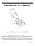
operator'sl
manual.,
MODEL NO.
358,7r96170
'
_/ , STCRRFTSMRN®t
r22.2CC GASOLINE
.•
EDGER
, • %,j•
2 Cycle
" !fl, WARN;NG:
read and follow all
Safety Rules, Precations and
Operating Instructions, Failure to do so can result in
serious personal injury,
Engine
Fuel Mix 16:1
= Assembly
=Maintenance
= Operation
= Repair Parts "
i_Always Wear Eye Protection During Operation
....
: Sold
666654-0108_t-01086: •
by Sears.
Roebuck
and
Co.,, Chicago.
Ill. 60684
U.S.A.
_'
•
-.
TABLE OF CONTENTS
• !Safety Rules, Cautions & Dangers ................
•Know YourUnit ...............................
:Assembly'. ..................................
_.Engine Information ............................
•
A. FuelingYour Unit ..........................
B. StartingInstructions.... ....................
: C. Pre-operationChecks .......................
D. Operating Instructions ......................
E. Engine Adjustments ........................
: Using YourEdger +............................
• A, Opera_nglnstructions
'
13.Settingthe DepthAdjusting Wheet .............
3
4
5,
6
6
7
7
8
8
9
.9
9
(3.OperatingTips ...........................
GeneralMaintenance .........................
A. DriveShaftLubrication.....................
B.BladeGuard .............................
C.Gear BoxLubrication. .....................
D. Edging Blade ............................
E,AirRlterCare ; ..... :......................
F. FuelTankUpkeep .........................
G. StarterRopeRepair .......................
H. TroubleShootingchart .....................
Accessories ................................
PartsLiSt ....................
_ ..........
QUick ReferencePage .........
:..............
SPECIFICATIONS
ENGINE TYPE:
DISPLACEMENT."
2-Cycle
AJr-Ooolad
22_cc
ENGINE RPM:
Operating-- 6500.7500
fdle--
IGNITION:
SWITCH:
.
"................
MUFFLER:
:
:..
,,
•
13,5g.<_
............
.024"i_26"
iiiiiiiiiiiiiii
, ",
iiiiiiii
AutoRewind
STARTER:
LUBRICATION:
Handlebar
';
i i
ii
i
..................
Gasoline/Oil
Mix- 16:1(SeePage6)
Blade Guard,.._
Ddve,_rt
.
Centd_gal
..........
FUELTANK:
......................
SPARKPLUG:"
D_aphmgm
AltPosPJon
with
.......
adjustablefuetmixture
jets
SPARK
PLUGGAP;.
u i
MODULEAIRGAP:
,,,,
,
LoTone- California
approved
sparkarresting
CLUTCH:
.....
SolidState
CARBURETOR:
...........
ON/OFF
2300-3800
, '
10
10
10
10
11
11
11
11
12
13
14
15.t8
.,. 19
(( l_
'
H
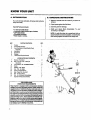
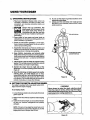
Fuel Cap
/
Depth
•Adjusting
"
•
rottleTdgger
"
"
.
.
'_
"
'
"
:"
M"
"
:
......
':
:
.........
"
'"
"
"
'
2
"
:
"
. .
"
•Model Number
:
MANUFACTUREDUNDER ONE OR MORE OFTHE
FOi.LOWING LI.S.PATENTS:3,708.967; 3,826,068; 3.859,776;
rr
_j_.
: 'Starter Rope Handle
4.035,912;4052,789; 4,054;g92;4,05"7,108; 4,104,797;
4.114.269;4.124,938; 4,156,312; 4.156,987; 4,161,820;
4DES
167,812;4,269,372;
4 296,675;
DF._,
249,630; DES, 255,764,
260,394iU.S AND
FOREIGN
PATENTSPENDING.
_::
SAFETY RULES, CAUTIONS
& DANGERS
Failure to observe the following Safety Rules and Precautions can resultin serious personal injury.
A.
KNOW
YOUR
6. Make sure the blade stops turning when the
throttle trigger Is released and the engine runs
at idle speed. For correction,refer to "Carburetor
Adjustments"page 8.
7. Stop the engine and let the unit cool off before
removing the fuel cap and refueling. Always
replace the fuel cap securely.
8. Keep all parts of your body away from the blade
when starting or running the engine.
9. Avoidbodilycontact withthe muffler. Usecaution
when changingoperating pos_ons The muffler area
can be hot and cause seriousbums.
10. Do nct overreach.Keepfirm footingand balance atall
times
11. Usetheedgerfromyourrightsideonly.Keepyour
lefthandonthe handlebar and yourrighthandon the
powerunithandle.
Direct the discharge of debds away from people,
animals, glass, and solid objects such as trees,
automobiles,
walls, e_c, asthe unit isbeing operated
12. The fast turning blademay causerocks, dirt, or sticks
to be thrown or to dcochet which may hurt people or
animals, breakglass, or cause otherdamage
13. Do not use the edger on graveled surfaces or in
extremely muddy areas.
14. Always push the unit slowly over rough ground.
StayaJert
for unevensidew_ks, holesinterrain,orother
similar conditions
15. Followthe stepsbelowif the bladestrikes a foreign
object or ff the unit operates abnormally. Stopthe
engine, disconnectthe spark ptug and inspectfor
damage Do not use until the unit isin proper workJng
• order
16. Stop the enginewhen the unit is not in use. Do not
leavea runningengine unattended.
17. Use only for jobs explained in this manual.
UNIT
1, Read your Operator's Manual carefully until you
completely understandand follow all safety rules,
precautions_ and operating instructions before
operating the unit.
2. Restrict your unit to users Who understand and
follow all safety rules, precautions, and operating
instructions in this manual,
13. PLAN
AHEAD
1.
Always wear eye protection. The
blade guard will not prevent rocks
and debris from being thrown or
ricocheting into the eyes and face
which can result in loss of vision or sedous per.
sona/ injur_.
2. Dress safely in long pants and wear boots or
safety shoe_ Do notwearloose clothing,
jewelry,short
pants or sandals; or go barefoot.
& Do not operate the unit when you are tired, ill, or
upset; or if you ate undertheinfluence of alcohol,
:
drugs or medication.
4. Inspect the area to be cut, Remove altdebris and
objectsthatcouldricochet,be thrownor couldotherwise cause injury or damage duringedging.
5. Keepchitdren, bystanders,andanimatsaminimum
_ :of30 feet (10 meters) away when starting oroperating the unit.
C. HANDLE
FUEL WITH
CAUTION
1. Eliminate allsoumes of sparks or flame (incfuding
smoking, open flames, or work that could cause
sparks) in the areas where fuel is mixed,pouredor
stored.
2. Mix and pour fuel in an outdoor area; store fuel in
a cool, dry, well-ventilated place; and use an
approved, marked container for all fuel purposes.
3. Do not smoke while handling fuel or while
• operating the unit.
• •4. Wipe up all spills before starting the engine.
5. Move at least 10 feet {3meters) away from fuel and
• fueling site before starting the engine.
E. MAINTAIN
YOUR UNIT PROPERLY
1, Have all service other then the items listed in this
manual performed byyour Sears Service Center,
2. Maintainthe unitaccording to recommended procedum,_
3. Disconnect the spark plug l_fom performing any
adjustment, inspection or maintenanc_ _pt
for
:
carburetoradjustment.
•4. Be certain the blade will not contact any object
D. OPERATE
YOUR UNIT SAFELY
before making engine adjustments.
1. Do not use any attachment other than those
5. Use only genuine replacement parts as recom.
supplied and recommended by Sears for usewit.h
: mended by Seam. The useofany part,or accessory
this unit,
not specifically recommendedfor thisunitmaycreate
2. Inspect the entire unit before each use for worn,
a hazardandlorvoid_ur warranty.
loose,missing or damaged parts. Do notuseuntilthe
; 6. Always drain fuel from the tank before storing the
unitis in properworkingorder.
3. Keep the handles free of oil and fuel.
unit for 30 daysor more,
4. Neverstartorruntheengineinsideaclosedroom
.....
7. D0notstomtheunitorfuelinactosedareawhere
• _
fuel vaporscan reach sparks oran openflame from
budding. Exhaustfumescontaindangerousearbon • ;
hot water heaters,.furnaces, etc.
, or
monoxide.
5. Never operete the edger without the blade guard
and handlebar securely in place,
r
: 8.
Storeinadryareaoutofthereachofchildren.•
J. _
........
r
SAVE THESE
INSTRUCTIONS
"
KNOW YOUR UNIT
,i
A, INTRODUCTION
.....
_':
B, UNPACKING
Yourunit willedge sidewalks,drivewaYsand curbspreciselyand neatly.
''
,
,,, ,,,,, ,,,,
INSTRUCTIONS
_
1. Remove contents from the carton ifyo u have not
doneso.
2. Check partsagainstthe listbelow.
Special Festums include:
3.: Examinepartsfor damage..:
* 7" inch reversibleblade
- Adjustable depth control up to 2 inches
1800blade shield
* Extended handlebar
- Total weight - 14.5tbs.
4. Notify your Sears Store immediately if a part
is missing or damaged.
KEY
NOTE: A rattle like noise in a powerheadwith an
emptyfueltankis a normalcondition,causedbythe
filtermoving againstthe wall ofthe emptytank.
CARTON CONTENTS:
QT_
1
Engine
2 . . Drive Shaft Assembly
3 , Gear BccdBl_e & Guard/Depth Wheel
Assembly
....
,4
Handlebar
5
6
Engine Oil
Grease
1
1
" "
1
1
........
" -
"
.
.
".Bolt
P_
'
'., _..
LOOSEPARTSBAGCONTENTS:
7
Bracket- Handlebar
:" •
- I/4 - 20 Xt-1/4"- Clamp &
8"
r
r
"
:
"_7-, LoosePartsBag(notshown)
..
Handlebar.,
L_k washer- 1/4. HandlebarBracket
Blade
Washer- 7/16-Blade
Nut -7/16-14- Blade
Clamp- EngineShroud
Bolt _Clamp t14.20 x9116"
Nut- 1/4-20- Clamp
Nut- I/4 -20 Brecht & Handlebar
Operator's Manual(notshown)
• !0.
11
12
13
14
15
16
1
1
"
1
_
2
--
2
.2
1
1
!
!
1
_TATEAND LOCAL
ORDINANCE REQUIREMENTS "
Your engine is equipped with a temperature limiting
muffler and spark arresting screen which meets the
requirements of California Codes 4442 and 4443. All
U.S.ForestLandandthestatesofCalifomia_
Maine,Oregon,
andWashingtonreqL_re
bylawthst¢_ertain
Internalcombus! tionenginesoperatedonfoP.st,brush,andgrasscovered
: amesbeequippedwitha temperature
fimitingmufflerand/or
sparkarrestingscreen.If you operate an intern!!corn: bustlon engine in astate or locale whe_ suchregulationsexist, you are legallyresponsibleformaintsining
the operating conditionofthese parts, Pailuretodoso
can subject you to liability or to a fine, .... .
' '
r,
:141"
.
,
'
"J
_k
.
,.
.
ASSEMBLY
Your Operator's ManuaJ has been developed to help you
assemble the unit and to understand its safe operation. It is
important that you read your manual completely to bacome
familiar with the unit before you begin assembly.
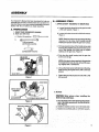
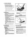
B. ASSEMBLY
1. DRIVE SHAFT HOUSING TO GEAR BOX
a. Loosenthe pinch clamp bolt on the gear box with
a 7116inch wrench. Figure 1.
A, PREPARATION
1. READ YOUR OPERATOR'S MANUAL
2. Tools you will need:
' •
a. Slotted Screwdriver
STEPS
b, Loosenthe index screw with a 5f16inch wrench.
Figure 1.
_'_
NOTE: Back the indexscrew out enoughto allow
clearance for the drive shaft housing but still
keeping the spacer insidethe gear box in place.
b.
11116inchwrench
(2)7/16inchwrenches
OF
c. Pull out about 6 inches of the flexibleddve shaft
from the driveshaft housing and inse_tthe square
end of the flexib!e drive shaft into the square
opening in the gear box. Figure 2.
(2) Adjustablewrenches
d, Push the drive shaft housing into the gear box
as far as it will go.
" NOTE: IfthePinch clampopeningl:0thegear-box-.istootight for the tube toenter, spread the opening slightly with a screwdriver.
•
L
,
':
e. Line up the index screwwith the holeinthe ddve
shafthousing and tighten firmlywith a 5/16 inch
Wrench.
f, _ghten the pinch clamp bolt securely witha 7/16
inch wrench.
Figure 1
DRIVE SHAFT
HOUSING
2. BLADE
DRIVE
SHAFT
Wear gloves when installing the
blade to help avoid injury.
iii iiii ii i
a. Placethe bladeonthe bladeshaft matchingtheflat
area ofthe blade openingwith the flat side ofthe
Shaft.Figure
" b. Install the washer and hex nut on the blade shaft.
• c- Tighten the nutfirmty with an 11116inch wrench.
NUT
Figure 3
•
3. HANDLEBAR
-.4. DRIVE SHAFT HOUSING
a. installthe handlebar bracketson the driveshaft
housingabovethedecal as shownin Figure4.
b. Installthefirsthexbolt, lockwasherandnutasshown
inFigure4.Tightenjustenoughto holdthebracket
in position.
"
c. lnstatithe handlebarin the bracketand alignthe
screwopeningsin thebracketand handlebar.
d. Insertthe handlebarintothebracket openingand
alignscrewholes.
e. Install the tast hex boil throughthe brackets and
handlebar,then install the Iockwasherand nutas
ShOWn Jn Figure 4.
f. Tighten both hex boltswith a ?/16r' wrench while
holding the nuts with another 7/16"wrench..
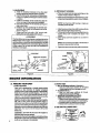
" a. Placethe clampfrom the loose partsbag,onthe
engineshroudas shownin Figure5.
b. Rt theendoftheflexibledriveshaftintothesquare....
shapedopeninginsidethe
engine shroud. Figure5.
.
" NOTE: Turnthe driveshafthousingorengine as
. necessaryto lineup parts.
c. Alignthe groovein the driveshafthousingwiththe
key insidetheengine shroudopening.
d. Firmlypushthedriveshafthousingstraightintothe
engine shroud until it bm'toms out (aboutl-tt2
inches).
• e. Installclamp screwand square nut as shown in
Figure5.
z_WARNING
The handlebar serves as a barder, and mustbe on the
left handside of theengine, Do not assemblethe clamp
'and handlebar to the drive shafthousing in a way that
allows the handlebar to be used on the righthand side
of the engine. Do not use the unit if the handlebar is
missing or damaged..
;
.
,,,,,,,,,
f, Tightentheclarnpscrewsecurelywitha screwdr'rver.
Figure 4
•
ENGINE
• A,
NOTE: Thenutmustbe mounted onthe tabsideof
theclamptokeep nutfrom turning.
Figure 5
INFORMATION
....
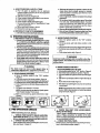
FUELING
YOUR UNIT
• 2. DO NOT USE:
• .!- Bib,OIL (Boating Institute of America) -1. FUEL MIXTURE
Does not haveproperadditives for air-cooled
Your unit is powered by a 2-cycle engine which
: "
2-cycleenginesand candamageyour unit.
requires a fuel mixture ot regular unleaded
,!. .- • AUTOMOTIVEOIL
gasoline and e high quality engine oil specifically
•:
, -- Does not have proper additives for 2-cycle
made for 2*cyele air-cooled engines. The internal
engir_s
and can_
damage.
designofthe2-cycleenginerequireslubricationofmov- .
• GASOLINE CONTAININGALCOHOL
ingparts.Thislubricationisprovidedwhenyouusethe
..- -.., (High Test, Premium orGasohol)
• recommendedmixture of gasolineand oil,
-- Stiffenscriticalcarburetor
fuel metering elements
' Gasoline must be clean and not overtwo months
and causesenginedamagefrom overheating.
'old; After a short periodof time gasolinebeginsto
....... , -- increases vaporlock (causeshard starting).
chemicallybreak down and willformCompoundsthat •
' _ Attractswatercausingcorrosiondamage.
cancausehardstartinganddamagein2-cycleengines.
Usingthe c0rrect measure of gasolineto oilisvery .
. 3. use THE FOLLOWING ONLY:
.important. Too much oil in themixture wiltfoul-the--. - :.--. • -.' • ._i:. "
_
r
6
t
_
_r'_,,'.
'
and
becomeselzed.
:..
-:;
:::
__
':
"
TOO little oil will cause theengineto ..
".
overheat
'
Alwaysmixthefuelthoroughlyinacontainersinca
..
!:- .. :J_ou,, I
thegasolineandoildonotreadilycombine.Donot
:i,'..
_
sparkplug.
I
'_
+
I
_L_,7 *_A__..I--L_
L___J
:'• ttYt°mixfueldirectlyin
thefueltank"
"•.
"_
'
_
::'_r_'_'_'_'
;';'''_
_:."
:"
''
r_
'__
.......
4. HOW TO MIX FUEL AND FILL TANK
a. Pour 1/2 gallon of. gasoline into an approved,
marked container.Do not try to mix oil and gasoline
directly in the fuel tank.
b, Add entire measureof EngineOil.
c. Cover container tightEyand shake for one minute.
d. Add remainder of gasoline.
e. Cover container tightly and shake again.
f. Removethefuelcap.Referto"Specifica_ons;'page
2, for fuel cap location.
g. Fill the tank using a spout or funnel
h. Reinstallthe fuel cap securely.
b. Eliminate ait sources of sparks or flame in the
areas where fuel is mixed, poured, or stored,
Thereshould be no smoking, open flames or work
. thatcou{dcausesparks.
c. Usean approved, marked container for all fuel
purposes.
d. MiXand pour fuel in an outdoor area. Store fuel
in a cool, dry, well-ventilated place. Gasoline
vaporsare harmful to your healthand can cause
serious hazards,such as explosion and fire. Use a
funnel or spout when pouring fuel.
e. Wipeup all fuelspills before startingthe engine.
f. Move at least 10 feet (3 meters) away from fuel
and fueling site before starting the engine.
5. IMPORTANT POINTS TO REMEMBER
a. Use only recommended fuel mixtures.
B. STARTING
INSTRUCTIONS
1. IMPORTANT POINTS TO REMEMBER
a. Stand inthe operating position (Figure 12,page
9 ) andtilt the unitto theleft, Whlfethe engine is
being started topreventthe blade fromcontacting
the groundor anyobject.
b. Pull the starter rope quickJyand sharptybut no
more than 10times to avoidflooding the engin_
if engine floods, push chokeknob in fully and pull
starterropesharplyuntilengine runs.Do notletthe
starterropesnapbackbetweenpulls.Holdtheham
die and lettherope rewindslowly.
if the blade does not turn when the engine is
accelerated, make surethe driveshaft housingis
propedyseatedin theengine shroud. Refer to"Drive
Shaft& DdveShaftHousing",page 6.
,
3. WARM ENGINE STARTING
a. Move the ignitionswitch to the "ON" position.
Figure9.
b. Pull choke knob until half choke position is felt.
Figure 7.
c. Grip rearhandleandsqueeze triggerwlth righthand.
d, Pull starter rope sharplywith left hand unti! engine
rUnS.
r
_W_NWNG
4. WARM ENGINE STARTING--
The blade must not turn at idle speed. Refer to
"Carburetor Adjustments'; page 8 for correction.
AFTER RUNNING OUT OF GAS
a. Moveignition
switchtothe "ON" position. Rgure 9.
.. b. Pull chokeknob tofullchoke position. Figure 6.
c. Gdp rearhandtewith right hand and squeezetrigger
fully.
d. Putlstarter rope sharply untilthe engine attemptsto
run.
e. Pushchokeknobin fully. Figure8.
2. COLD ENGINE STARTING
a. Move the ignitionswitch to the "ON" position.
Figure9.
b. Pullchokeknobto fullchoke position.Figure6.
Gdprearhandleandsqueezetdggerwithdghttrend.
d. Pullstarterropesharply untilengineattemptstorun.
e. Pushchokeknob inuntilhalf chokepositionisfelt.
Figure7.
f. Pullstarterropesharply 2- 3 times.
NOTE: Ifengine doesnotrunafter2to 3putts,repeat
"Cold Engir)eStarting" from stepb.
g. After 5 second warm up,pushchol_ knob in fully.
.
f. PullstarterropeuntJlengineruns,
butnotmorethan
4 moretime_
NOTE: Ifenginedoesnot runafter4pulls,itcoutdbe
flooded.Wait a few minutesend repeat procedure
using halfchoke.Figure7.
i•i.
Figure 8
Before operating your unit, always:
1. _-- CHECK OVER SAFETY RULES AND PRE"
CAUTIONS IN THIS Operator'sManual. Makecer"
•
lain you completelyunderstand and follow eachone.
•
2. _,, CHECK THE AIR RLTER.
.
Cleanthe filterifdirtybeforeoperaf]ngthe unit.Forloca"
' • tion, see Rgure 17,page 12.....
:.
"
J
I
"
Figure g
_
_|
r
Figure 10
'
: 3. ,! CHECK THE UNIT FOR LOOSE BOLTS,
NUTS, OR FITTINGS;
:
Tighten,rep_r or replaseparts as necessary.Youwill
_
need a Phillipsscrewdriverin addition to the tools
shownonpageS,Useontygenuinereplacementparts
_as recommendedby Sears.
: 4_ ,I CHECK THE FUEL TANK.
' , .._lfvi=tha ciean, fresh fuel mixture accordingto instruc.. tionsin fuel mixture section, page 6.
7.
:
''"
:
_
:'::"
r"
C* PRE-OPERATIONCHECKS
•
r"
Avoid any bodily contact with the muffler when the
engineis warm. The mufflerarea can be hot and cause
serious burns.
i_WARNING
Figure 7
.'
e. Push choke knob in fully. Figure 8.
.
• D.
OPERATING
INSTRUOTIONS
i1,11,i
.
3. Always releasethetriggerand allowthe engine to
return toidle speed when not cutting.
4. Make sumthe bladestopsturning whenthethmttie trigger is released and the engine runs at idle
speed. For correction,referto "Carburetor Adjust.
rnents';page 8.
5. Stop engine by moving the ignitionswitch to the
"OFF" position. Rgure t0.
Formaximum performance
and efficiency:
1. AJwaysaccefemtetheengine tothe desiredspeed
before cutting.
2. Never operate the engine at a higher speed than
necessary.
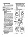
E' ENGINE ADJUSTMENTS
c, LOW SPEED MIXTURE ADJUSTMENT
L CARBURETOR ADJUSTMENTS
1.) Allow enginetoidle,
2.) Turn Low Speed Mixture Screw clockwise
slowly. Notethepositionatwhichthe
engine speedisreduced.
3.) Turn the screw slowly counterclockwise
. Notethe positionatwhichthespeed
isreduced.
:_" 4.) Set the screw mid-way between these two
extreme posit_on_.
The carbum=tor
has been carefully adjusted at the
Pactory+
Due to changes in altitude and operating
conditions,yourcarburetormay requireadjusting.To
maketheadjustment,followthe procedurebelowvery
caretutly.
a. PREPARATION
1.) Use fresh fuel mix,Refertopage6.
2.) Removeair filter.See Figure17,page 12.
•,. 3.) Turn bothlowspeed and highspeed mixture.
:
scows clockwise _
untilfully dosed,
but do not overtighten.
4.) Unscrewboth mixture screws one full turn
countemlockwise_
.
.
b. IDLE SPEED ADJUSTMENT
_
1,) Turn Idle Speed Screw clockwise
untiiitstops.Donotovertighten.Openscrew :.
onefulfturn countemtockwise,<-._
......
2J Start the engine and edge for 3 minutesto
: '+
warm up engine.
•"
_) Allow engine to idle,
*
4.) AdjustldlsSpeedScrewuntiltheenglnecontinuesto run without stallingand wtthoutthe
r
bfadeturning.
"
'
lure the screwclock_+se _
_ increase+
engine speed if engine :
stalls,"
....
Turn the screw counterctock_se _
tO
slow engine down
and/or to keep the
: .
bladefromturning.
1CAUTION: ] Highand low speed mixtureeettingsare
highly critical adjustments. If set incorrectly,psrma:. nent damage will occur to the engine. Both thelow
speed mix screw and the high speed mix screw
ICAUTION: I Re-check Idle speed, if the engine stalls
or bladetums, repeat "idle Speed Adjustment"
Do not operateengine atfutlthrottle for
:prolonged periods while making high speed
adjustments as damage to the engine can occur.
'
... . / i .
d. HIGH SPEED MIXTURE ADJUSTMENT
.
1.) Supportthe shaft sothat the blade is offthe
•........
groundand willnotcontact anyobject.
_pr
2.)
+. :: , ,.--_3.)
. " i.
: : ..
i:: : .... . "+
..
4.)
+ '" , -
Squeezethrottle
triggerwide
open.
Turn.theHigh
Speed
Mixture
Screw slowly
clockwise, _
untiltheenginespeedis
reduced,Note position.
Turn the screw slowly counterclockwise
_
. Stop whenthe enginejust beginsto
runrough.
..- 5. ) Turnthescrew slowly theminimum amount
'
cloclodse
_
untilthe engine runs
smoothly.
e. CHECK ACCELERATION
• .
Allowtheenginetoidie, Squeezeldggetandcheck
' + engine acceleration. If the engine does notaccelerate smoothly,you may have to repeat steps
"b.3)" through "d"
" should be in the range of 3/4 to 1.1/4 turns open.
NOTE: Generally,byturningtheLowSpeed Screw
counterclockwise _
a smallmount, the
• unitwillaccelerateproperly.
:*.......
::
'
L..
:
Figure11
:_Thealrflltermustbeflttedintothe
comers of thehousing to avoiddamage to the
engine..-
,. L:/ ' ! i :._.+' + +
, i"-i'
AtR FILTER
f. REINSTALL AIR RLTER
2:SPARK PLUG
Check spark plug and replace as necessary.Set the
...... : electrodegap at .025".
•
r
,
r
,
USING YOUR EDGER
A. OPERATING
INSTRUCTIONS
10. Do not use the edger on graveted surfaces or in
' extremely muddy areas.
11, Always pushthe unit slowly over rough ground.
Stayalertforunevensidewalks,holesin terrain, or other
,simita[ conditions.
1. Read your Operator's Manual. Make certainyou
• completely understand and follow a_l safety rules,
precautions, and operating instru_ons before you
operatethe unit
2.
Always wear eye protection. The
blade guard will not prevent rocks
and debris from being thrown or
ricocheting into the eyes and face
which can result in loss of vision or serious personal injury.
3. Dress safely in long pants and wear boots or
safetyshoes. Do notwearIooseclothing,
jewelry,Short '
pantsorsandals; or go barefoot.
4. Check the unit before operation. Lookfor worn,
loose,missingor damaged parts.Do not useuntilthe
unit isin properworkingorder.
5. Inspect the area to be cut. Removeall debrisand
objectsthat could ricochet, be threvm or could otherwisecauseinjuryor damage during edging.
& Keep children, bystanders, and animals safely
away.Beforesta_ng ffTeengine and duringoperation,
make certainpeople and animals are a safe distance
; away from the work area-- a minimum of 30 feet (10
meters)
.
LOCKED POStTtGN_
:r
the blade to the left while the engine isbeing
• ,started. Thiswill helppreventthebJadefrommaldng
.... contactuntilyou are readytobegin edging.
_.
Tilt
& Operate the edger from the right side of the
body only. The correctoperatingpositionisshownin
Ftgure12.
9. Direct the discharge of debris away from people,
animals, glass, and solid objects such as trees,
automobiles,watis,etc.,as the unitis beingoperated.
The fa_ turningblademay causerecks,dirt,or sticks
to be thrownor to ricochetwhichmay hurtpeopleor
animals,break glass, or cause other damage,
il. SETTING
THE DEPTH ADJUSTING
WHEEL
_YOUt"
edger isequippedwith a large p_asticwheel which
helpscontrolthe depthof edging.
.
Never attempt toadjust the depth adjusting wheel
when the engine is running. Always stop the engine,
wait until the bladestops
turning, and disconnect the
.....
_WARNING
spark plug before making adjustments.
Tosetedging depth:
1. Loosenthe large pisstic knob ontheback ofthe blade
guard. Figure 13.
_2.
....
Raiseor lowerthe wheel to obtainthe desired edging
depth
i!& Tv3htentheknobhandtight`Donotusetoolstotighten
as parts can become ovettightened and possibly
•
damaged.
:
: ,
NOTE: If the area to be edged has neverbeen cut or
severalweeks have passedsince the last cut, the first
edgingshould notbe deeperthanl/2 inch.
•
Figure 13
C. OPERATINGTIPS
6. ifthe bPadestalls,immediatelyraise the bladefrom
thecut bylowering the engine, ifthebladecontinues
tostallwhen raised,stopthe englneand inspect for
blockageordamage.Referto "Blade Guard',section
below.
7. Alwayskeepthe blade areaolean. Stoptheengine,
makesure thebladehascompletely stoppedturning,
and disconnectthespark plug beforecleaning.
Asyou becomefamiliar withyouredger,youwillbeai0teto
determineyourownpaceforusingit.Conditionssuchas
depthofcutandmaterialbeingcutwillregulatethespeed '
and timerequiredfor youredgingjob.
• i. Increasetheenginespeadbeforapiaclngtheblsde
in the cut. AllowengIne to warmup for one minute
beforeyoubeginedging,
2. Runthe engine at fullthmtUe whilecuffingfor bast
operation,
.3. Keep your edging path straight by guiding the
depth adjusting wheel fiat on the walkway. Figure
14.
DEPTH" ADJUSTING
4. Always work going away from people and solidobiects, such as walls, large stones, trees,
automobiles, etc,
5. Be careful when edging near trees or valuable
plants. The highspeedmetal blademaycutrootsand
causedamage tothe plant_
A. ,DRIVE
MAINTENANCE
SHAFT
LUBRICATION
' o Lubricate the Rexible Drive Shaft:
/
|CAUTIONi t Laythe flexible drive shaft 0n a clean
surface.Avoidlaying theshafton theflo0r, ground
, _: oronanysurfacethatmayhavedirtordebd_Even
..... after wiplngthe shaft, grease restduecan pick up
dirtparticlesthatcan cause damage or premature
.failure.
;;:-- After each ten (10) hours of operation;
. "•
-- Before operating ifthe unit has been stored for
•
90 days or longer.
• Use Drive Shaft LubePart No. 30102.
"
NOTE: A tubeofgreasehas been suppliedwithyour
unittobe used after thefirst 10 hoursor=operation.
• 4. Usinga cleancloth,thoroughlywipethesurfaceof
theflexible driveshaftto remove enyoldgrease.
5, Applyauniformcoatofdriveshaftlubetotheentire
surfaceoftheflexible drive shaft.
r
GENERAL
Figure 14
• Obser/e the following precedure for best results:
1=Loosenthegearboxindexscrewandpinchclamp
bolt. Refer toFigure 1, page 52. Removethedriveshafthousingfrom thegear box.
3 PulttheflexJbledrfveshaftfromthehousing,
•'
-.
NOTE: Check theflexible
driveshaft
forwear or '"
.damage.Replaceifbrokenwires,
twists
orkinksare
found.
• B,, |LADE
,:" •
..
•
;......
:.
='
r
"
6. Injectthe remainingcontentsofthe tube provided
---: 'into thetopofthe driveshafthousing.
..Z Replace flexible drive shaft in the ddve shaft
. housing.
8. Followinstructions
onpage6 toreassemb_ethe
drive
shafthousingto gear box.
3. Removethethreescrewsand washershOtdingthe
bladeguardtothe gear bc0(.
GUARD
Keep mud, grass, weeds, etc. cleaned from the
blade, blade guard, and depth adjusting wheel. •
Binding can occur if grass or other material is
eaughtbetween the btadeguardand the shaft.The
clutchwlilslipand theblade willnottum.
e >TOcorrect a binding condition:
"
4. Removeforeign material.
• .. 5- Reinstallthe blade guard and hardwarecarefully
...
topreventbindingto the shaft collar.
• .-_:..:6. Testthebladebyhandtobesurethebladewillturn
easily afterthepartsare reassembled.
r
ii- " I.CAUTIO_NEt
Weargloveswhenhandtingthebladel
: ' :_. i NOTE:lfadragonthebladeisfeft,
toosenthethree
.!': . to help avoid injury.
"
"
•"........
. ' ......
' screwsandrepositionthebladeguard.Repeatthe
'. _r
_+• :'1. Discennectthesparkplug.
,
"
:: . '.iii. : ;ihandtest.Oontinue_ad_ustaccordinglyuntilthe
,
,,
bladetumseas ly
.i !:i' 2. Removetheedgingblad_:(RefertoEdging
Blade,
.".';i, •,
"''"
J
"
_
_
"
'
r
'
"
1
+
+
=
r
......
T
C,. GEAR BOX LUBRICATION,
Check the Gear Box for lubrication:
e At the beginning of the edging season;
• Frequently,when the unit isused du ringunusualty
dusty conditions or high temperatures,
...
1, Removetheplugon thetopofthe gear box. Figure
t5.
2. Ifthe gearbo×looksdry,fill itwih lubdcent.
NOTE: Use Gear Lube #28 -HT 59071
3. Replace the plug,rnakingsure thefiber washerisin
place.
D.
EDGING
Figure 15
BLADE
• The Blade is reversible, When one cutting edge
becomes dull,the bladecan be turnedover and the
otheredge used.
• Replacethebladewhenbothsidesbecomewom
to where only 1/2 inch can be used for edging.
• TO turn the blade over or to replace: _ '
I" Disconnectthe sparkplug,
2. Holdtheedger firmlyona hardsurfaceto preventthe
bladefrom turning,
3, Using a 7/16inch wrench, turn hex nut counter°
clockwise _
. Figure 16,
'_ ' r
NOTE: Hold the blade against the gear box wh_e
removing the nutand lockwasher to keep the shaft
from turning.
4. Turnthe bladeoveror replace.
5. Place the bladeon the blade shaft matching the
flat area of the blade openingwith the fiatside of
the shaft.
6. Attach the hexnut to the shaft and turn untilhand
tight,
7, Trghtenthe nut firmty witha 7/16inch wrench,
Wear gloveswhen handlingthe blade
-. tO help avoid injury.
z_WARNING
Do not alterthe blade or use any blade ormplacement
part that is not recommendedbySearsto avoidserious
pbrsormlinjury.
r
,
E. AIR FILTER
CARE
A dirty air filter decreases engine performance and
• increases fuelconsumption.
Clean the Nr Filter:.
• Frequently;
• Alwaysaffer 5tanks offuel or 5 hoursof operation,
whichever is less.
1. Removetheair fitter.See Figure 17,page 12,
2, •Washin soapand water
"
..
': " "
_:
•
;_ 3. Squeezefleer dry.
,,. • _4.
Reptacetheairf_ter,
.=.
:•:_: ,,
"'
ICAUTtON: t Do not Clean filter in gasoline or
otherflammablesolventtoavoidcreatingafire
hazard.
"
.......
"
[CAIJTION:J Theairfiltermust befittedintothe
corners of the housing to avoid damage to the
engine.
"
"
_"
• ....
Ill I
II
I
I
I
I
Figure 16
I-. FUEL
TANK
UPKEEP
Never use gasoline ina fuel mixture that is morethan
2 monthsold. Gasoline begins to break down after a
periodof time andw_lfo_mcompounds that causehard
. startingand damage in2-cycleengines.
!- Inspect the unit for fuel leaks each time it is used.
. Repairor replacepartsas necessa_
- . -2: Usinggasoline or rue/mix over2 months old will
cause the engine to be difficult or impossible to
• start/
r -:
3. Drainfuel tank or allowunitto run out offuel before
slodng the unit fol; 30 da_ or morn.
".11
G, STARTER ROPE REPAIR
20 Holdtheropetautand make2 completeturns
ofthe
pulleycounle_ockwise _
to placetension
on thepulley.Holdthepulteytore_intension.
21. Alignpulleynotchwithrope
exithole,pullstarterhandietothefullextentoftheropeandallowtheropeto
. ".
stowtywindaroundthepulley.
NOTE: While the.unit is disassembled,inspect
the carburetorhousing seal and replace if worn.
'
Figure19.
9.2,Reverseprocedurefor re*assemblyoffan housing
toshroud.
23. BesuretoguideChokeKnobthroughtheholeintine
fanhousingdudng re*assembly.
• Repairthestarter rope Ifthe mpebreaks nextto thq
pulley.
• Replace the starter rope if it breaks 2-3 inches
awayfromthepulleysince the ropewillbetoo short •
to repair.
Always wear eye protection when servicingthestarter rope.The recoilspdng,
4
sion.•i_,WARNING
ifthespdng popsout, serious per- I
locatedbeneath
pulley,is undertensonal
injuP/ can the
result_
To repair or replace:
1. Drainall fuel from tank.
2. Separatefuelline at fuel line connector.
3. Rernovetwo(2)screwsandtwo(2)washersfremfuel
tank.Figure 17.
4, Separatefueltank from fan housing.. ' •
5, Remove the five {5) screws from the fan, housing.
Figure 18.
6, Separatefan housing from shroudabout 2inches.
7, Disconnectignition modulewires.Figure19.
8., Slide hightension lead grommetfrom slot in fan
- housing.
9. Separate the fan housing completelyfrom the
•shroud. Figure 19.
10. If the starterrope is not broken, releasethe spring
tension bypulling about 12 inchesof rope fromthe
,putley and catch the rope in the notch as shown.
:Figure21.
NOTE: The tension on the starter springwill be L •
releasedif the rope has broken.
11. Removescrewandpulleyverycarefully.Figum20.
.The recoil spring which tiesbeneath the pulley
must stay in the housing, flat against the bo_. tom. Ifthespring is disturbed, it wglrequireconslderabletime and effort tO reinstall Twistthe
pulleygently clockwise _
as youpull up to
releasethe spring,
12.Moveawayfrom the fuel tankand melt theend ofthe
• new ropeto go into the pulley.
!3. Allow the melted end of the ropeto driponce; then
whilethe rope isstill hot, pull themelted endthrough
a clean rag _ obtaina smooth,pointed end.
"{4.Insert rope through the rope exit hole in the fan
, housing.
t5o
G uideropeinsidepulleyand upthroughthetopsida
. pulleyholetothe outsidebypushingthe ropefrom
the undersidehole with a smallobjectsuchas a
Phillipsscrewdriver'.See insert, Rgure 19.
16.Wraprope counterclockwise_
aroundpulley
' ratchet and tuck loose end back under rope
leavinga i14to112inchtail layinginthe ropegroove.
See insert,Figure20.
17, Wind all but about 12inches of the rope ¢ountar_: 'clockwise 4[--,,_ aroundpulley.
•18.Replacepulleyin thehousing.Be surethepulleyis ',i."
all thewaydownandthespring issecured. Replace
'_ s_rewand tighten.Figure20.
" . ":
19.Hold the 12inch slackin the rope and catch ropein
. pulley notch.Figure21.
12 ..
i
' Figure18
IGNITION
MODULE
Rgum 19
H, TROUBLE
SHOOTING
CHART
:
TROUBLE
CAUSE
.......
,,,,,,,
Engine will not start
...........
11Ignition switch off.
"' _:
2. Fuel tank empty.
3. Spark plug notfiring.
4. Fuel not reaching carburetor,
1. Moveswitohto "ON".
2. Filltankwith correctfuel mixture.
3. install newplug.
4. Chackfordirtyfuel filter; clean;Check
for kinkedorsplitfuel line;repairor
replace,
5. See StartingInstructions.
6:,Co aeyou[ arsSe ce n*e,.
I. ldling speed set too tow.
1. Adjustidlespeedscrewclockwiseto
increasespeed.
2, Adjust idle speedscrewcounterclockwise to reduce speed.
3. See Carburetor Adjustments.
4. Contact your SearsService Center.
5. Contact your Sears ServiceCenter.
properly
I 2. Idlespeed set too high.
& Lowspeed screw requires adjus_zenL
4. Crankshaftsealsworn.
5. Compression low.
Engine wiii not...........
accelerate, lacks
power or dies
undera load
Enginesmokes
excessively
Engine runs'hot
I.
2.
3.
4.
FuelMixtureIncorre'_:'"
"
SparkPlug Incorrect.
Carbonbuild-up.
HighSpeed Mixture set too low.
,L
idle speed
,,,,,,,,
....
,,, ,,
Blade does not turn
when engine is
accelerated
Blade stops
under a load
""i:
: 1. Carburetorrequires adjustment.
2. Airfilterdirty.
3. Sparkplug f_ufed.
4. Carbonbuild-up.
5. Lowcompression.
,,, ,,,
c rbu tor
Adj.str.e .
"
2. Clean or replace air filter,
3. Cteanor rspface spark plug and regap.
4. Contact your SearsServiceCenter.
5. Contact your Sears Service Center,
.... 1. ChokepartiaUyon.
2. Highspeed needle requiresadjustment.
3. Airfilter dirty.
4. Oil rich fuel mixture.
.
+
REMEDY
5. Engine flooded.
6. Compression low.
I
r
1.
2.
3.
4.
Pushchokein.
See CarburetorA_ustments.
Cleanorreplaceairfilter.
Emptyfuel tankand refillwithcorrect
fue! mixture.
.......... 1. See FuelingYourunit.
2. Replacewith correct plug.
3. Contactyour SearsServiceCenter.
4. See Carburetor Adjustments.
..................
i
.....
,,,,,,,,,
,,
1. Carburetorrequ_resa_ustment,
2. Clutchrequiresrepair.
1. Driveshaftnotengaged,
2, Carburetorrequiresadjustment.
3. Clutehslipping.
1. See CarburetorAdjustments.
2. Contactyour SearsServlceCenter.
t. See Assembly lnstruct_ons.
2. See CarburetorAdjustments.
3. ContactyourSearsServiceCenter.
1, Driveshaft not engaged.
2. Carburetorrequiresadjustment.
3. Clutchslipp_ng.
1. See AssembJyInstructions.
2, See CarburetorAdjustments.
3. ContactyourSearsServiceCenter.
13
ACCESSORIES
'
The followingaccessories
areavailablethroughSearsRetail Stores,CatalogOutletsor ServiceCente_
•' 2 Cycle Engine.Oil ' :
Shaft _be
Gear Lube
......................
.
Edger Blade R placement
_
-.*..o..=.._w
Stock No.
Part No
_.******
•
NOTES
.._.
' .. ,Stock No,
" Stock No.
_
. _
'.,,
71 36555
30102
28-HT5S071
85731
.
5
6
7
8
9
10
tI
15
16
17
18
19
20 _
:
94415
92327
1
t
92324
92348
_
" 1721
92059
1
1
1
I
I
_"D551285
.1
STD541425
92343
93_19
97=818
15209
10396
ST0,551225
1
1
1
1
2
1
3
21
15426
3
22
23
24
25
923.39
91574
92326
915-'75
2
I
1
1
1
1
1
1
t
28
29
30
92329
92325
. 92557
92354
92278
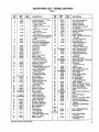
Drive Shaft HousLqgAssembl; ....
Shoulder-Bolt:-Wheel#5/16-18x 5/64"
Washer- #_eel
Wheel - Depth Adjusting
Bracket - WheeJ
Lockwasher - #5/16- Wheel to Bracket
Nut-Bracket to Guard - #5/16-18-Hex
Knob-Wheel
Washer - #1/4 -Knob
,:
Loc_'_ut-Braokdt to Guard - #1/4_.20
Blade
I Lockwasher -#'7/16-Blade Mounting
Nut - #7t16-.14 * Blade Mounting
Washer - #I/4 - Bracket to Guard
Guard AsSembly
Lockwasher- #//4 - Guard to Gear
Housing
•
Screw .Guard to Gear Housing #t/4-20 X 1/2f"
Sleeve. Drk_eShaft Tube
Retaining Ring
Retaining Ring.- Pinion
Bearing-Sealed
"
Bearing -Ope_ '
Gear - Pin_on
Lockwasher - #10 - Index ,Screw
Screw - Index-#10-24 × 1_"
Lo_washer 1/4- Pinch Clamp
31
32
_3
34
.35
35"
37
39
40
4I
42
43
44• 45
46
_7
50
•
92353
92333
92335
92336
923,37
92338
1648
94427
1642
15197
92554
92332
92_.31
• 92334
91402
• 94418
92352
QTY.
RE(_
I
_
1
1
1
1
2
2
2
2 '
1
1
1
1
1
1
1
51
• 52
53
92308
92556
92265
1
I
1
54
55
Decals
101
I02
103
30102
1
1
sss_
27O68
27070
27269
DESCRIPTION
Screw- Pinch Clamp - #1/4-20x 1-3f16"
Shaft - Output
_ear;ng. Large
RetainingRing
Seal - O_
Collar - Shaft
Bolt - Bracket #1/4-20 x 1-114_
B_oket - Handlebar
_Lockwasher - #1/4. Bracket
NUt. Bracket - #I/4-20 - Hex
DriveShaft Assembly
Gear Housing ,
Bearlng-Smalf
:
Gear
Grip. HandieSt
Handlebar
Screw - Lubrioat_onFiller#5/16-18 x 3/8
Spacer 5/16- F_ber - Pinch Cramp
Washer - Rber
Gear Housing Asserr_ly
(ln_ #'s22-36, 43-45 & 50-52)
Drive Shaft Lube
I Operator's Manual
'
1
3
PART
NO,
NO.
r
DESCRIPTION
REQ.
I r
1
I
DecaJ-HandlebarLocation
Decal-Guard
t Decal" B_de Ro_a_Jon
.
KeyNo:s Excluded:_, 12,1& 14 & 38;
.
15
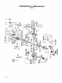
SEARS PARTS LIST-,
,. ,,
r'. r
MODEL 358.796170
,
1 -----_
12 16
' 98
4799
/
!3
48-
15
t02
54
7
SEARS PARTS LIST-
MODEL 358;796170
Figure 2
•
+,+ ,
,
_
-
..... ,,, ,,
KE f
NC,
PART
NO.
DESCRIPTION
REO.
t
,2
3
10729
25377
92243
1
1
1
4
107/1
1
5
15509
2
6
15158
2
15590
4
8
10
11
24371
23575
15594
!
12
13
14
!5
16
17
18
19
20
26119
10842
" 22290
21045
91878
30115
42067
26048
69182
21
' 22
23
24
24569
39122
69182
30054
Fuel Cap Ass'y+(incl. "O" Ring)
Bracket - Fuel Tank
8c{ew - Bracket/Handle
(#t/4-10x 1-1/_")
Fuel TankAss'y. (Inc.#t, 12,15
&16)
7
:
1
1
1
1
1
1
1
1
1
lS12a
26
15479
27
5TD541131
L_ ,
1
2
1
1
4
•42059
15127
89114
+15168
24.303
25472
21044
19O59
_'q'D60060_
36
37
38
39
40
41
42
43
44 .
Screw. Crankcase
(#10-24 x 5/8" Fil.)
Knob - Choke
Fitting - Fuel Line
Fuel Line - Carburetor
Seal - Crankshaft
Screw- Clamp
#8-32 x 5/16" Pan
Clamp- Choke Wire
Screw+Ignition Module
(#8-32 x 3/4" Seres)
Tab45 ° - Electrical
Grommet- Plug Wire
Lead Wire - High Tension
Seal +CarburetorCase
t_,oot- ChokeJWire
Wire - Choke
Crankcase Ass'y. •
,+.+/'
,
. (IncL #33 & 52)
Screw - Carburetor
+ "
(Shoulder- #10-24x 24/8") [
Wave* #t0- Washer
: ; +.
Shutter- Choke
"
:
1
2
25995
24435
_ 39082
19105
23378
26236
"t
46
'
+,15404
•
:';.
47
48
: '24558
,
54
FlywheelAss'y.(incl.#2a)
1
.1
1
2
1
24651
49
50
51
52
53
Screw -#10 x 1"+FuelTank
55
Fan Housing
56
Washer +#10- Fuel Tank!
57
Fan Housing
58
Screw- Fan Housing Top/Shrou_
59
Side #!0-24 x 518" Bind. Hd.
Air Filter
60
Nut- GroundingSwitch
. 61
Screw - Fan Housing Bottom
62
- #10-14x 1-118"Bind. Hd,
Check Valve - DuckBill '
63
FanHousing
64
Rope (35 it.)
Une - Fuel
65
" 67
Fuel Filter Ass'y.
Engine Oil
68
Starter+Recoil Spring
Starter+Pulley
69
7O
Grounding Switch Kit
71
(Incl. #10, 21, 22 & 39)
72
Washer -Ground Terminal
73
Lead Wire -- Ground
Ignition Module Kit
Crankcase Seatam- 3 oz. Tube
7.=
(Not included withunit)
7E
Washer - #10Regular73
Starter Pulley
7_
Screw- StarterPulley
7_
(#10_3/4" Hex Head)
Nut - Flywheel
B1
Spring- Starter Deg
B_:
Washer- Flywheel
+
2
NO.
.+
!,
_A
E_
37
)1
_3
)4
_5
)7
)_
01
O2
PART
NO.
26237
35183
19115
32058
15351
15126
10849
15162
25413
19111
15239
DESCRIPTION
27266
Plate- Guide, Choke Wire
Carburetor(WA 149)
Gasket- Ca,,buretor
Bearing - Crankshaft
Thrust Washer- Cranksh_lt
Key - Flywheel
Crankshaft & Rod Ass'y. (Ind. #72)
Retainer -Wr'_ Pin
Piston Ring
Gasket- Cylinder
Screw - Cylinder (#tl4-20 x 314"Soc. Hd.)
Connector: Spark Plug
Boot -Spark Plug
HighTensionLead Ass'y.
(incl. #41,60 & 61)
Screw- Carburetor
(#10-24x 1-7/8" Fil. Hd.)
Screw- Carbureto[ Cover
Cove'- CarburetorCase
CarburetorCase Ass'y,
Ga:_ket+CarburetorCase/ "
Crankcase.
Reed Valve
Washer _Reed Valve
Screw #6-19 x 5/16" - Reed Valve
Bearing - Wrist Fin
PistonAss'y
(Inc.#56,57 & Pin)
Cylinder
Diffuser - Muffler
Spring - Muffler Attachment
Spark Plug (0J-14)
Body- Muffler
Screen- SparkArrestor
Co_r- Muffler
Kit- Clutch Washer
Kit- Clutch Ass'y.
(incl. ClutchWasher)
Trigger- Throttle
Washer- #8 Regular. Throttle
Screw-#8-16 x 318"- Throttle
Drum & Coupling.ass'),.
W&sher- Flat+#10Shroud
Handle
Screw- #10-24 x 718"Shroud
-+
Clamp .....
Nut* #12-24 Square
.
. ,
Shroud
-:
Bolt - #1/4_20 x 9/!,6" +Clamp
Ass'y Rope and Handle
Spring- Fuel Line Protector
S (Upper)
+"
:
pring - Fuel Line Protector
27063
27064
Decal, Startingin_ucdons
Decal-ON/OFF..+:. - " :
3933
3934
39103
15379
26O29
10453
19108
24438
23367
32057
10753
12O95
_6949
24903
24362
24.364
24361
69196
69194
25342
15382
15407
10797
15274
26592
26560
15610
26549
15609
26792
27265
Decal:Shr0ud (Right), '... " "
"i Nolghown " "'_ " "
:
Decal- Shroud (Le_t)-. i
":_ " :
. NotShown "_ E!-.- . ... - •
•
Key No's. Excluded:# 9 86,92 & 96
+
•
++%
.,
..+
+ .
: ,
:
.,.
,,
+
117.
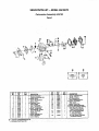
•SEARS PARTS LIST -- MODEL 358.796170
Carburetor
Assembly
#35183
Figure 3
5
:
•-
r_
....
.i
KEY
PART
NO.,
NO.
' 1""
35O17 '
2
"r35191
3
" 35164
4
35158
5 '"
"_35178
6
35166
7
35133
8 . .... 35007
QTY.
REQ.
"
!
!
1
.1
D_-S_R1PTION " "
Screw- PumpCover
Pump CoverAss'y(incl.#4)
"
_+Gasket-Pump
'Screw- Idle Adjustment
+Semen-inlet
-.
_=+Dlaphragm- Pump
Valve-ThrolU_
-...
,"_"
Clip-,Throt_eShaft
.,
.
NO.
PART
NO.
17
18
19
20
21
22
23
24
35O36
35142.
-35028
: 13.=,01S
35147'
35042
35137
35151 "
QTY,'
Kwik Repair /
k
|
Gasket
,_
DEsc.l_r,o,
Sp_g-HiSp_N_re
I
Needle - HISpeed
I •
+Pin - Metering Lever
-.1
Sc.m'_-Matedng LeverPin
1
! _+Gaskat-Circu_t Plal_ .
.
1 •
Plate- Cimuit.
..
1
1
I +_crew-Circuit Plate
1
1 ' /,_,+Gasket-Metering Diaphragm
.1
*+Diaphragm Assembly-M_drlg.r
--.
.ScrewAssemblyo Metering
i'10
9" " " " 35138.
I " : +Scrd_v-ThmttleYalve
8pdng-Thr_tleRelum.,
3_}14
35015 i ' ' :. "1:
, ,':_, ,' --.
. 25
26 .
35153': - " • 1
4 .-"
.: Cover&Thrott;leSIl_LttClip -. .
11
"351_
_
. Sh_-ft_-sembly-Thlottle.: "_': :"::i.._ ":.,
I
....
!';
" Cov_r-MeteringDiaphragm
.
.12
":.:35023 ::_.' :' I. ',;.- Spdng-tdleNeedle
L "
..: ,. i ..27 =. , 351;49 .1.3
-35t41 .
i.:;_ =.
Needle-Idle
..' ." .._
28,: .:.051_, :_ .'1 ,_Kit=Carb. KwikRepOt
:. (4- IndicatesOontents)
' " -.
14
-' 35139:
.....,"t _. ._, :f-Sprlng-MeleringLever.. :, . 'i _ | .
.,
'" ."
.'t_t - O_,arb,
G_skel I Diaphragm
"15 "
.35106
,"1
+_Ive -Intel Needle
" "29
35186" "
" "I
' (*lndlcatesOomer_).
":16 .... .35031
•:'f
+Lever-Metering
......
., .:......
'
'_
r
_B * Contents ofGasketJDiaphragm
t_t
.
" . ""
"
r
'
_
"
....
-_.
I¸
_=
,
28
I
"
Hll
re,Hi
,,,,1
,.,,
..l=
, H
H
..H
,,,,,i
H
=
..m
,,,,,,
. ,
QUICK
REFERENCE
PAGE
-
v
Read and follow all safety rules, precautions
and operating instructions.
Failure to do so can result in serious personal injury.
_.
.
PREPARATION
3
toWear eyeprotection....
.....
2_ Dre_ssafely- boots or safety shoes, long pants.
3. Check for worn, loose, missing or damaged parts and repair.
4. Inspect and make safe the area to be cut,
5. Keep children, bystanders,and animals a minimum of 30 feet (10 meters) away.
"
:1.Eliminate all sources of sparksor flamewhere fuel is mixed, poured or stored.
2. Use gasoline not over 2 monthsold.
3. UseI pad air._;ooled,2-cycleengine oilto 16 parts regular unleadedgasoline
4, Mbc'andpour fuel in anapproved, marked containerin an outdoorarea.
5. Move a minimumof 10feet (3 meters)away from fuel endfueling site beforestarting engine.
STARTING THE ENGINE ...............................................................
1.Holdthe unit_ntheoperatingposi_onand tilt the bladetothe left.
2. Move the ignitionswitchto the"ON" position.
3. Pullthe starter ropeno more than 10 timesto avoid flooding theengine.
4. Keep the throttle trigger depresseduntilengine runs.
OPERATING THE UNIT .........................
: .....
1.Acceleratethe engine tothe desiredspeed before cutting.
2.
_e engine toidle when not cutting.
3. Stop the engine by moving theswitch to the "OFF" positon.
:
_
;
_
:
_
_
;
_
:
_+
_
7-8
..
_ - : "- . ............
!" •" ."':. "i":8, !0 & 1!
MAINTENANCE
.. 13-15
!, Disconnectspark plugbeforeperformingmaintenance exceptfor carburetoradjustment.
2. Drainall fuel from theunit beforestoringfor 30 daysor more.
& Lubrfcatetheflexible driveshaftafter each 10 hoursofoperationand afters_ring for more than 90 days,
4, Clean air filter frequently but alwaysafter 5 hours 0f operationor 5 tanksoffuel,whichever isless.
5. Store in a dryplaceout of the reachofchildren,
IIIIIIIIII
page
. ..
II I I
....
III
IIIIII
I
,+
......
-,
.
•
.
,,
The Model Numberwillbe found onthefan housfngwiththeSerial Number,Always
mentiontheModelNumberwhen requestingserviceor repairpartsforyourunit.
Allpartslistedhereinmaybe0rderedfromanySearsServiceCenterand mostSears
Stores.
WHEN ORDERING REPAIR PARTS ALWAYS GIVE THE FOLLOWING INFORMATION AS SHOWN IN THIS LtST,
!;'T:.hePARENUMBER
operator's
manual
.
3. The PART DESCRIPTION
" .::..:::
::
...
2. The MODEL NUMBER
358.796170
4. The NAME OF ITEM -22.2¢c Gas Edger
Ifthepartsyouneed are notstockedlocally,yourorderwillbe electronically
transmitted toa SearsRepairPartsDistributionCenterforexpeditedhandling.
Whenyoubuy memhandlsefrom Sears
you getan extrasomethingthatnobody
elsecanoffer.Sears ServicP.
Acrosstownoracrossthecountry,
Sears
. Servicefollows
you,providing
trustworthy,
competent
service technicians•using
QnlySearsspecifiedfactory parts.
'
"
r
"
4
_
r
MODEL NO.
358.796170
'
How to Order r
Repair Parts •
,
,
-
. .',. , • :
_
SEARS SERVICE
J>>"
'
'""
I"'
"
"
"
:
:
.'_':
......
.' - !:, : .
.,
.
. :'
:
.
•
'.,
. .....
.,
YourSearsMerchandisetakesonaddedvaluewhenyoudiscoverthatSearshasServiceUn_mugl_utt_
counW. Each is staffed by_ars-Tr_t,
pmlessional_hni.
ciansusingSearsapprovedmethods,
_
IS AT YOUR SERVICE
_:66665-1-01086-1-01086, ':
.