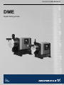
1
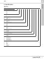
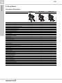
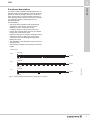
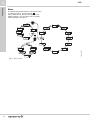
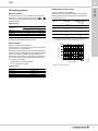
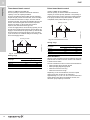
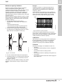
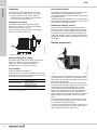
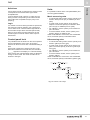
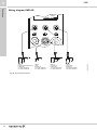
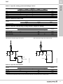
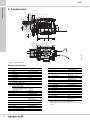
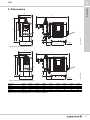
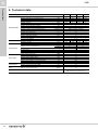
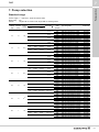
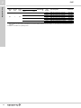
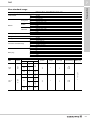
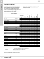
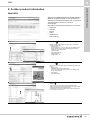
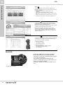
GRUNDFOS DATA BOOKLET DME Digital dosing pumps DME Table of contents 2 1. 2. 3. General data 3 Performance range Digital Dosing 3 4 Identification 5 Type key 5 Functions 6 Overview of functions Functional description Control panel Menu Operating modes Dosing monitoring Control panel lock Units Wiring diagram DME-AR 6 7 8 10 11 14 15 15 16 4. Construction 18 5. Dimensions 19 6. Technical data 20 7. Pump selection 21 Standard range Non-standard range 21 23 8. Pumped liquids 24 9. Further product information 25 WebCAPS WinCAPS GO CAPS 25 26 27 1 DME General data 1. General data Performance range p [bar] DME 18 16 14 12 10 8 DME 60-10 DME 375-10 6 4 DME 150-4 DME 940- 4 0 1 Fig. 1 12 60 150 375 940 Q [l/h] TM04 8478 0612 2 Performance range DME 3 1 DME Digital Dosing represents state-of-the-art technology. This patented Grundfos solution sets new standards, including new principles and methods. TM04 8479 0612 General data Digital Dosing Fig. 2 DME pumps Precise and easy setting The operator can easily install and set the pump to discharge exactly the quantity of dosing liquid required in the application. In the display, the setting of the pump is read out directly in ml/h or l/h, pulse or batch, and the operation mode is easily identified by means of icons. Unique technology A unique drive and microprocessor control ensure that dosing liquids are discharged precisely and with low pulsation even when the pump is operating with high viscosity or degassing liquids. Instead of the conventional stroke length adjustment, the capacity of the DME is regulated by automatic adjustment of the motor speed during the discharge stroke and by fixed suction stroke speed, ensuring optimal and uniform mixing. Fewer variants to cover all needs The pumps feature a powerful variable speed motor, a turn-down ratio of 1:800 and a complete control interface including: • Full pulse control • Pulse batch control • Internal timer batch control • Analog 0/4-20 mA control • Level control • Fieldbus communication module. This ensures that the DME pumps cover the range from 60 to 940 litres per hour up to 10 bar. The switch mode power supply ensures that the same pump is working precisely, irrespective of the mains supply (100-240 V, 50/60 Hz). The DME dosing pumps feature diaphragm dosing head with integrated vent valve, suction and discharge ball valves. The pumps are fitted with power cable and plug. 4 2. Identification Type key Example: DME 60- 10 AR- PP/ E/ C- F- 3 1 A1 F Identification 2 DME Type range Maximum capacity [l/h] 60 150 375 940 Maximum pressure [bar] 4 10 Control variant AR AP B Standard Standard + Profibus Basic Dosing head material PP PV SS Polypropylene PVDF Stainless steel 1.4401 Gasket material E T V EPDM PTFE FKM Valve ball material C G SS T Ceramic Glass Stainless steel 1.4401 PTFE Control panel F S Front-fitted Side-fitted Voltage 3 1 x 100-240 V, 50/60 Hz Valve type 1 2 Standard Spring-loaded Connection, suction/discharge A1 A2 A3 A4 Q Threaded, Rp 3/4" Threaded, Rp 1 1/4" Threaded, NPT 3/4" Threaded, NPT 1 1/4" Hose 19/27 and 25/34 Mains plug F G I B J E L EU UK Australia USA Japan Switzerland Argentina 5 3 DME Overview of functions DME 60-940 AP TM04 8789 1313 DME 60-940 AR TM04 8827 1413 DME 60-940 B TM04 8826 1413 Functions 3. Functions Capacity control, see page 11 Internal stroke-frequency control Internal stroke-speed control ● ● ● ● ● ● ● ● ● ● ● ● ● ● ● ● ● ● ● ● ● ● ● ● ● ● ● ● ● ● ● ● ● ● ● ● ● ● ● ● ● ● ● ● ● ● ● ● ● ● ● ● ● ● ● ● ● ● ● ● ● ● ● ● ● ● ● ● ● ● ● ● ● ● ● ● ● ● ● ● ● Control panel, see page 8 Capacity setting in litres, millilitres or US gallons Display with background light and soft-touch buttons Easy set-up menu with language options On/Off button Maximum capacity button (priming) Green indicator light for operating indication Red indicator light for fault indication Control panel lock Side-fitted as an option Operating modes, see page 11 Manual control Pulse control Analog 0/4-20 mA control Timer-based batch control Pulse-based batch control Functions, see page 12/14 Dosing monitoring Dual-level control Calibration of pump for the actual installation Anti-cavitation (reduced suction speed) Capacity limitation Counters for strokes, operating hours and power on/off Fieldbus communication Overload protection Error message in display Diaphragm leakage sensor ★ Dosing signal output ● ● ● ● ● ● Power supply, see page 14 Switch-mode power supply Inputs/outputs, see page 17/17 Input for pulse control Input for analog 0/4-20 mA control Input for dual-level control Input for external start/stop Alarm relay output (variant AR) Dosing output Input for external on/off switch ★ When dosing crystallising media, a diaphragm leakage sensor must be installed. DME-B is not suitable for crystallising media. 6 3 DME Functions Functional description The electronically controlled variable-speed motor of the DME pump provides optimum control of the stroke speed. As shown in the figure below, the duration of each suction stroke is constant while the duration of each discharge stroke varies according to the capacity set, resulting in optimum discharge flow in any operating situation. The advantages: • The pump always operates at full stroke length, irrespective of the capacity set; this ensures optimum accuracy, priming and suction. • A capacity range of 1:800 for each pump size. • Smooth and constant dosing ensuring an optimum mixing ratio at the injection point. • Significant reduction of pressure surges preventing mechanical stress on diaphragm, hoses, pipes, connections and other dosing parts exposed to leakage and wear. • The installation is less affected by long suction and discharge lines. • Easier dosing of highly viscous and gas-containing liquids. Capacity setting Discharge 100 % Duration Suction 50 % Discharge Duration 10 % Discharge Duration Suction Fig. 3 TM01 8944 0900 Suction Relation between stroke-frequency adjustment and capacity 7 3 DME Functions Control panel Maximum capacity button ml/h 4 3 2 6 7 100% 1 Fig. 4 8 TM04 8481 0612 5 Control panel Pos. Description 1 Maximum capacity button (priming) 2 Navigation/settings 3 Menu/accept LCD display 5 Navigation/settings 6 Green indicator light 7 Red indicator light 8 On/Off button TM04 8702 5112 4 Front-fitted control panel Fig. 6 Side-fitted control panel TM04 8703 5112 Fig. 5 8 If the maximum capacity is required over a short period of time, for example during start-up, press the 100% button on the pump control panel. When the button is released, the pump automatically returns to the previous operating mode. To set the pump to run for a specific number of seconds at maximum capacity, press the 100% and buttons simultaneously. The remaining number of seconds appear in the display. The maximum value is 300 seconds. To stop the pump before the set time has passed, press the button. This feature is useful when flushing the pump. Indicator lights and alarm relay output Operating state Pump running Green indicator light Red indicator light Display On Off Normal indication Alarm relay output ★ 1 Functions 3 DME 1 2 3 NC NO C Set to stop Flashing Off Normal indication 1 2 3 NC NO C Pump fault Off On EEPROM 1 2 3 NC NO C Supply failure Off Off Off 1 2 3 NC NO C Pump running, low chemical level ★ 2 On On LOW 1 2 3 NC NO C Empty tank ★ 2 Off On EMPTY 1 2 3 NC NO C Analog signal < 2 mA Off On NO mA 1 2 3 NC NO C Insufficient dosing according to signal from dosing monitor ★ 3 On Overheating Off On NO mA 1 2 3 NC NO C On MAX TEMP 1 2 3 NC NO C Internal communication failure Off On INT COM 1 2 3 NC NO C Internal Hall failure ★ 4 Off On HALL 1 2 3 NC NO C Diaphragm failure (leakage) ★ 5 Off On LEAKAGE 1 2 3 NC NO C Max. pressure exceeded ★ 5 Off On OVERLOAD 1 2 3 NC NO C More pulses than capacity On On MAX FLOW 1 2 3 NC NO C No detection of motor rotation ★ 4 On On ORIGO 1 2 3 NC NO C ★ 1 Applies only to control variant AR. ★ 2 Requires connection to level sensor. ★ 3 Requires activation of the dosing monitoring function and connection to a dosing monitor. ★ 4 Please contact a Grundfos service centre. ★ 5 After the fault has been rectified, press to reset alarm. ★ 6 The pump makes 10 attempts to restart before going into permanent off mode. 9 3 DME Functions Menu The DME dosing pumps feature a user-friendly menu. To activate the menu, press the button . During initial start-up, all menu texts appear in the English language. You can set the menu to display other languages, see page 14. TM04 8484 0612 mA Fig. 7 10 Menu overview 3 DME Operating modes The pump ensures constant dosing according to the quantity set in l/h or ml/h by means of the and buttons. The pump automatically changes between the measuring units. Applies to DME-AR and DME-AP The pump ensures dosing according to an external analog signal. The dosed capacity is proportional to the input value in mA. Setting Input signal Dosed quantity as a percentage of the max. capacity ★ 4 mA 20 mA 4 mA 20 mA 0 mA 20 mA 0 mA 20 mA 0% 100 % 100 % 0% 0% 100 % 100 % 0% Setting range Pump type DME DME DME DME 60 150 375 940 4-20 (default): Setting range From [ml/h] To [l/h] 75 200 500 1200 60 150 376 940 When the anti-cavitation functions is enabled, the maximum flow is reduced (see page 12). 20-4: 0-20: 20-0: ★ If a maximum capacity limitation has been set, the dosed quantity is a percentage of the set capacity limitation (see page 13). Pulse control [%] [%] [%] 100 100 100 DME DME DME DME 60-10 150-4 375-10 940-4 80 80 80 60 60 60 40 40 40 4-20 4-20mA mA mAsignal ssignal ignal 4-20 20 20 20 000 000 444 888 12 12 12 Input signal [mA] Fig. 8 Setting range Pump type Maximum capacity [%] Applies to DME-AR and DME-AP The pump doses according to an external pulse signal, for example from a water meter. There is no direct relation between pulses and dosing strokes. The pump automatically calculates its optimal speed to ensure the required quantity is dosed for each pulse. The quantity to be dosed is set in ml/pulse. The pump adjusts its speed and/or stroke frequency according to two factors: • The frequency of external pulses • The set quantity per pulse. 16 16 16 20 20 20 [mA] [mA] [mA] TM04 8485 0612 Manual control Functions Analog 0/4-20 mA control 4-20 mA control Setting range [ml/pulse] 0.000625 - 120 0.00156 - 300 0.00392 - 750 0.00980 - 1880 11 3 DME Pulse-based batch control Applies to DME-AR and DME-AP The set quantity is dosed in batches at maximum capacity or the set capacity limitation. The time until the first dosing (NX) and the following sequences (IN) can be set in minutes, hours and days. The maximum time limit is 9 days, 23 hours and 59 minutes (9:23:59). The lowest acceptable value is one minute. IN must be higher than the time required to perform one batch. If IN is lower than the time required, the next batch will be ignored. In case of supply failure, the set dosing quantity, the IN time and the remaining NX time are stored. When the supply is reconnected, the pump starts up with the NX time at the time of the supply failure. Thus, the timer cycle continues, but it will be delayed according to the time of the supply failure. Applies to DME-AR and DME-AP The set quantity is dosed in batches at maximum capacity or the set capacity limitation. The quantity is dosed every time the pump receives an external pulse. If the pump receives new pulses before the batch is completed, these pulses will be ignored. Quantity per batch t Pulse Quantity per batch TM04 8831 1513 Functions Timer-based batch control Pulse Fig. 10 Pulse-based batch control TM04 8830 1513 Setting range NX IN Fig. 9 Timer-based batch control Setting range Pump type DME DME DME DME 12 60 150 375 940 Pump type DME DME DME DME 60 150 375 940 Setting range From [ml/batch] To [l/batch] 6.25 15.6 39.1 97.9 120 300 750 1880 Anti-cavitation Setting range From [ml/batch] To [l/batch] 6.25 15.6 39.1 97.9 120 300 750 1880 When the anti-cavitation function is selected, the pump extends and smooths its suction stroke. This results in a softer suction stroke. The anti-cavitation function is used in these situations: • When pumping high-viscosity liquids • When pumping degassing liquids • When the suction line is long • When the suction lift is high Depending on the circumstances, the motor speed during the suction stroke can be reduced to approximately 75 %, 50 % or 25 % of the normal motor speed. When using the anti-cavitation function, the maximum pump capacity is reduced. Maximum capacity limitation makes it possible to reduce the maximum capacity (MAX. CAP). It influences the functions in which the pump normally operates at maximum capacity. Under normal operating conditions, the pump cannot operate at a capacity higher than the one stated in the display. When pushing the maximum capacity button, the pump operates at 100 %. With the maximum capacity limitation function, a large pump can be set to operate as a much smaller pump. Together with the 1:800 capacity range, this function allows the following: 1. To utilize the smooth and even dosing characteristics of the pump at low capacities to achieve – improved chemical mixing – improved dosing through long discharge lines – improved dosing of high-viscosity liquids. 2. To improve the dosing of gas-containing liquids: In a large pump, the displaced volume (1) is much larger than the non-displaced volume (2). 1 Example: A DME 376 receives a 12 mA input signal from a control instrument. According to the analog curve (see page 11), this results in a 50 % output and a capacity of 188 l/h. A new situation occurs where it is only necessary to dose 47 l/h: The maximum capacity limitation is set to 94 l/h. The pump is still receiving a 12 mA signal resulting in a 50 % output and a capacity of 47 l/h. Q [l/h] 376 188 94 47 0 0 2 4 6 8 10 12 14 16 18 20 [mA] TM04 8791 1313 Maximum capacity limitation Functions 3 DME Fig. 12 Maximum capacity limitation The maximum capacity limitation also reduces the pump speed in timer-based batch control, pulse-based batch control and during calibration where the pump usually operates at maximum capacity. 1 Calibration After start-up, the dosing pumps can be calibrated for the actual installation to ensure that the displayed value (millilitres or litres) is correct. A calibration program in the set-up menu facilitates calibration. Counters 2 Small pump Large pump TM04 8832 1513 2 Fig. 11 Anti-cavitation 3. To cover several needs with just one pump size. 4. To adapt the pump to a 4-20 mA signal control with 4 mA corresponding to 0 % and 20 mA to the set maximum capacity. This allows you to use a DME for dosing a very small quantity of liquid without having to change the input signal. The pump can display non-resettable counters for: • "Quantity": Accumulated dosed quantity in litres or US gallons. • "Strokes": Accumulated number of dosing strokes. • "Hours": Accumulated number of operating hours (power on). • "Power ON": Accumulated number of times the mains supply has been switched on. 13 3 DME Functions Languages Bus communication The display text can be displayed in one of the following languages chosen in the set-up menu: • English, German, French, Italian, Spanish, Portuguese, Dutch, Swedish, Finnish, Danish, Czech, Slovak, Polish, Russian. The DME-AP is available with a built-in module for bus communication with PROFIBUS DP systems. This module enables remote monitoring and setting via the fieldbus system. All DME features are available via bus communication. The PROFIBUS GSD-files can be found on the product CD included in the standard delivery. Integrated vent valve The DME dosing pumps are provided with an integrated vent valve (1). The vent valve makes priming during start-up very easy. The vent valve must be connected to the tank by means of a 15/20 mm PVC hose. Diaphragm leakage sensor The pump can be fitted with a diaphragm leakage sensor. The sensor is connected to the drain hole of the dosing head. In case of leakage of the diaphragm, the signal from the sensor generates an alarm in the pump, and the alarm relay is activated. When dosing crystallising media, a diaphragm leakage sensor must be installed. 1 TM04 8486 0612 Dosing monitoring Fig. 13 Integrated vent valve The DME pump incorporates a switch-mode power supply. This makes the pump independent of variations in supply voltage and frequency. Operating range: 1 x 100-240 V, 50/60 Hz. Level control Applies to DME-AR and DME-AP The pump can be connected to a level control unit for monitoring of the chemical level in the tank. The pump can react to two level sensor signals. Level sensors Upper sensor activated Lower sensor activated Pump reaction • • • • • • Red indicator light is on. Pump is running. Alarm relay is activated. ★ Red indicator light is on. Pump stops. Alarm relay is activated. ★ ★ Applies to control variant AR. 14 TM04 8790 1313 Switch-mode power supply Fig. 14 Dosing monitor mounted on pump discharge side The dosing monitor is designed to monitor the dosing of liquids which may cause gas accumulation in the dosing head, thus stopping the dosing process even if the pump is still operating. During the dosing process, the dosing monitor gives pulse signals to the monitor input so that the pump can compare performed dosing strokes (from internal stroke sensor) with externally measured physical strokes (from dosing monitor). If an external dosing stroke is not measured as a result of the internal dosing stroke, this is considered a fault that may have been provoked by empty tank or gas in the dosing head. The dosing monitor should be connected to the input for dosing monitoring (pins 4 and 5). This input must be configured for dosing monitoring. Once the input has been set to dosing monitoring and a dosing monitor has been connected and set, the dosing monitoring function will be active. 3 Definitions Units Correct dosing stroke: A pulse from the dosing monitor corresponds to the internal stroke signal within acceptable time. Incorrect dosing stroke: There is no pulse from the dosing monitor corresponding to the internal stroke signal within the acceptable time (the pump is not pumping). It is possible to select metric units (litre/millilitre) and US units (gallons/millilitre). Logic If a number of incorrect dosing strokes are performed, the pump will continue operating, but it will change over to alarm mode. The red indicator light will be on and the alarm output will be activated (variant AR). When a correct dosing stroke is detected, the red indicator light is turned off and the alarm output is deactivated. Functions DME Metric measuring units • In manual and analog modes, set the quantity to be dosed in litres per hour (l/h) or millilitres per hour (ml/h). • In pulse mode, set the quantity to be dosed in ml/pulse. The actual capacity is indicated in litres per hour (l/h) or millilitres per hour (ml/h). • For calibration, set the quantity to be dosed in ml per 100 strokes. • In timer and batch modes, set the quantity to be dosed in litres (l) or millilitres (ml). Under the QUANTITY menu item in the COUNTERS menu, the dosed quantity is indicated in litres. US measuring units It is possible to lock the buttons on the control panel to prevent maloperation of the pump. The locking function can be set to ON or OFF. The default setting is OFF. A PIN code is required to change from OFF to ON. When ON is selected for the first time, the indication "_ _ _ _" appears in the display. If a code has already been entered, the code will appear when an attempt to change to ON is made. This code can either be reentered or changed. • In manual and analog modes, set the quantity to be dosed in gallons per hour (gph). • In pulse mode, set the quantity to be dosed in ml/ pulse. The actual capacity is shown in gallons per hour (gph). • For calibration, set the quantity to be dosed in ml per 100 strokes. • In timer and batch modes, set the quantity to be dosed in gallons. Under the QUANTITY menu item in the COUNTERS menu, the dosed quantity is indicated in gallons (gal). Operating display TM04 8762 1213 Control panel lock Fig. 15 Possible units settings 15 3 DME Functions Wiring diagram DME-AR 2 3 5 1 4 2 3 5 1 4 2 3 1 4 2 3 2 5 4 1 Cable 1 Analog/pulse/leakage sensor Product No. 2 m cable: 96440447 5 m cable: 96440448 Fig. 16 Wiring diagram DME-AR 16 1 2 3 1 Cable 2 Relay Product No. 2 m cable: 96534214 5 m cable: 96534215 1 3 5 2 Cable 3 External stop Product No. 2 m cable: 96527109 5 m cable: 96527111 4 2 3 1 Cable 4 Level sensor Product No. 2 m cable: 96440450 5 m cable: 96440451 TM02 7069 2503 3 3 DME Pin holes Function 1/brown Pulse Pulse Analog Batch Batch Leakage Leakage 2/white 3/blue, 5 V X 5V X X 5V X 4/black GND (-) mA input Plug type 5/grey contact 5 VDC mA signal contact 5 VDC contact 5 VDC (+) mA input GND X 5V Functions Cable 1: Input for analog, pulse and leakage sensor X GND Cable 2: Output for alarm relay Pin holes Function Alarm relay output NO Alarm relay output NC 1/brown 2/white X X X 3/blue X Cable 3: Input for external stop, dosing monitor, output for dosing Pin holes Function 1/brown External stop input External stop input Dosing monitor input Dosing monitor input 2/white X 5V 4/black Plug type 5/grey X contact 5 VDC contact 5 VDC GND X GND open collector ★ Dosing output (pump running) ★ 3/blue, 5 V X X 5V GND NPN Open collector can be used for a relay or a lamp. With internal 5 VDC power supply: max. 100 mA With external power supply: max. 24 VDC, 100 mA Relay Lamp TM03 7869 5006 Power supply TM03 7868 5006 Lamp 24 VDC Cable 4: Input for level sensor Function Low level Low level Empty tank Empty tank ★ Pin holes 1/brown 2/white X★ 5V 3/blue, 5 V 4/black 5/grey X★ contact GND X★ 5V Plug type X★ 5 VDC contact GND 5 VDC The function for the potential-free contact set can be chosen from the display (NO = Normally Open and NC = Normally Closed). 17 4 DME Construction 4. Construction 29 20 28 27 26 25 24 23 1 2 3 4 38 21 22 19 18 17 16 15 5 6 14 39 12 11 10 9 32 36 37 8 33 34 7 35 31 TM04 8488 0612 30 Fig. 17 Sectional drawing Material specification Pos. Description Material options O-ring EPDM/FKM/PTFE Material options Back plate PPE/PS 20 % glass fibre 23 2 Spring DIN 17223 TYPE C 24 Valve seat PP/PVDF/SS 1.4401/PTFE 3 Housing PPE/PS 20 % glass fibre 25 Valve ball 4 Hall sensor - Ceramic/Glass/SS 1.4401/ PTFE 5 Operation PCB - 26 6 Power cable Rubber 7 Gear 8 9 Valve casing PP/PVDF/SS 1.4401 27 ★ Spring Alloy C-4, 2.4610 (NiMo16CrTi) - 28 O-ring EPDM/FKM/PTFE Brushless DC motor - 29 Valve, complete - Drain hole or leakage sensor - DME 60 and DME 150: 19/25 mm hose nozzle PP/PVDF DME 375 and DME 940: connection with internal thread 1 1/4" NPT / Rp 1 1/4 PP/PVDF 11 Union nut 12 14 15 10 16 17 18 Pos. Description 1 30 ★ ★ Dosing head cover Steel 31 Dosing head PP/PVDF/SS 1.4401 32 Safety membrane - 33 Power PCB - 34 Crank shaft Steel PP/PVDF 35 I/O PCB - Connection, complete - 36 Connecting rod Steel O-ring EPDM/FKM/PTFE 37 Steel plate Steel Venting valve, ball Ceramic 38 Steel frame Steel Spring Alloy C-4, 2.4610 (NiMo16CrTi) Diaphragm Textile-reinforced EPDM, PTFE-coated Spring Alloy C-4, 2.4610 (NiMo16CrTi) ★ The pump is available with spring-loaded valves. Spring material: Alloy C-4, 2.4610 (NiMo16CrTi) ★★ The steel plate is not included in stainless-steel dosing head version. 18 Venting valve, body PP/PVDF 19 Venting valve, tap PP/PVDF 20 O-ring EPDM/FKM/PTFE 21 End cover Steel 22 Venting valve, complete - 39 5 DME A B Dimensions 5. Dimensions G TM02 7062 5106 D C F E 4xØ7 I H Fig. 18 Dimensions of DME 60 and 150 l/h A F G TM03 7884 5006 D C B E 4xØ7 I H Fig. 19 Dimensions of DME 375 and 940 l/h Pump type DME DME DME DME 60 150 375 940 A [mm] B [mm] C [mm] D [mm] E [mm] F [mm] G [mm] H [mm] I [mm] 198 198 238 238 176 176 218 218 331 345 410 430 284 284 364 364 180 180 230 230 444 444 543 543 41 28 95 75 74 74 95 95 187 187 246 246 DME 375 and 940 are equipped with 1 1/4" thread connections. 19 6 DME Technical data 6. Technical data DME Mechanical data Weight and size Maximum Maximum Maximum Maximum Maximum Maximum Maximum Maximum capacity capacity with anti-cavitation 75 % capacity with anti-cavitation 50 % (approx.) capacity with anti-cavitation 25 % (approx.) pressure stroke frequency suction lift during operation suction lift when priming with wet valves Signal input Signal output Sound pressure level 20 DME 150 DME 375 DME 940 60 45 33.4 16.1 10 150 112 83.5 40.4 4 376 282 210 101 10 940 705 525 252 4 160 6 1.5 Maximum viscosity with spring-loaded valves ★ [mPas] (= cP) 3000 mPas at 50 % capacity [mPas] (= cP) 200 [°C] [°C] [°C] [°C] 50 0 45 0 ±1% Maximum power consumption P1 Enclosure class Insulation class Power supply cable Voltage in level sensor input Voltage in pulse input Minimum pulse-repetition period Impedance in analog 0/4-20 mA input Maximum loop resistance in pulse signal circuit Maximum loop resistance in level signal circuit Maximum load of alarm relay output, at ohmic load Maximum voltage, alarm relay output Maximum sound pressure level Approvals ★ DME 60 Maximum viscosity without spring-loaded valves ★ Maximum liquid temperature Minimum liquid temperature Maximum ambient temperature Minimum ambient temperature Accuracy of repeatability Weight Diaphragm diameter Supply voltage Maximum current consumption [A] Electrical data [l/h] [l/h] [l/h] [l/h] [bar] [stroke/min] [m] [m] Maximum suction lift: 1 metre. [kg] [mm] [VAC] at 100 V at 230 V [W] [m] [VDC] [VDC] [ms] [] [] [] [A] [V] [dB(A)] 11.4 79 11.8 21 22.5 106 124 173 1 x 100-240 V, 50/60 Hz 1.25 2.40 0.67 1.0 67.1 240 IP65 B 1.5 H05RN-F with plug 5 5 3.3 250 250 250 2 42 70 DME 60-150: CE, cCSAus, GOST DME 375-940: CE, cCSAus, GOST 7 DME Pump selection 7. Pump selection Standard range Power supply: 1 x 100-240 V, 50/60 Hz switch-mode Mains plug: EU Valves: Single-ball on suction side; single-ball on discharge side Max. capacity [l/h] 60 60 150 150 376 376 940 Max. pressure [bar] 10 10 4 4 10 10 4 Control variant Materials Dosing Gaskets head Valve balls PP EPDM Ceramic 19/27 25/34 PP FKM Ceramic 19/27 25/34 PVDF FKM Ceramic 19/27 25/34 SS PTFE SS 1.4401 Rp 3/4 PP EPDM Ceramic 19/27 25/34 PP FKM Ceramic 19/27 25/34 PVDF FKM Ceramic 19/27 25/34 SS PTFE SS 1.4401 Rp 3/4 PP EPDM Ceramic 19/27 25/34 PP FKM Ceramic 19/27 25/34 PVDF FKM Ceramic 19/27 25/34 SS PTFE SS 1.4401 Rp 3/4 PP EPDM Ceramic 19/27 25/34 PP FKM Ceramic 19/27 25/34 PVDF FKM Ceramic 19/27 25/34 SS PTFE SS 1.4401 Rp 3/4 PP EPDM Glass Rp 1 1/4 PP FKM Glass Rp 1 1/4 PVDF FKM Glass Rp 1 1/4 SS PTFE SS 1.4401 Rp 1 1/4 PP EPDM Glass Rp 1 1/4 PP FKM Glass Rp 1 1/4 PVDF FKM Glass Rp 1 1/4 SS PTFE SS 1.4401 Rp 1 1/4 PP EPDM Glass Rp 1 1/4 PP FKM Glass Rp 1 1/4 PVDF FKM Glass Rp 1 1/4 SS PTFE SS 1.4401 Rp 1 1/4 AR B ★2 AR B ★2 Connection ★ 1 AR B ★2 AR Control panel position Front Side Front Side Front Side Front Side Front Side Front Side Front Side Front Side Front Side Front Side Front Side Front Side Front Side Front Side Front Side Front Side Front Side Front Side Front Side Front Side Front Side Front Side Front Side Front Side Front Side Front Side Front Side Front Side Type designation DME DME DME DME DME DME DME DME DME DME DME DME DME DME DME DME DME DME DME DME DME DME DME DME DME DME DME DME DME DME DME DME DME DME DME DME DME DME DME DME DME DME DME DME DME DME DME DME DME DME DME DME DME DME DME DME 60-10 AR-PP/E/C-F-31QQF 60-10 AR-PP/E/C-S-31QQF 60-10 AR-PP/V/C-F-31QQF 60-10 AR-PP/V/C-S-31QQF 60-10 AR-PV/V/C-F-31QQF 60-10 AR-PV/V/C-S-31QQF 60-10 AR-SS/T/SS-F-31A1A1F 60-10 AR-SS/T/SS-S-31A1A1F 60-10 B-PP/E/C-F-31QQF 60-10 B-PP/E/C-S-31QQF 60-10 B-PP/V/C-F-31QQF 60-10 B-PP/V/C-S-31QQF 60-10 B-PV/V/C-F-31QQF 60-10 B-PV/V/C-S-31QQF 60-10 B-SS/T/SS-F-31A1A1F 60-10 B-SS/T/SS-S-31A1A1F 150-4 AR-PP/E/C-F-31QQF 150-4 AR-PP/E/C-S-31QQF 150-4 AR-PP/V/C-F-31QQF 150-4 AR-PP/V/C-S-31QQF 150-4 AR-PV/V/C-F-31QQF 150-4 AR-PV/V/C-S-31QQF 150-4 AR-SS/T/SS-F-31A1A1F 150-4 AR-SS/T/SS-S-31A1A1F 150-4 B-PP/E/C-F-31QQF 150-4 B-PP/E/C-S-31QQF 150-4 B-PP/V/C-F-31QQF 150-4 B-PP/V/C-S-31QQF 150-4 B-PV/V/C-F-31QQF 150-4 B-PV/V/C-S-31QQF 150-4 B-SS/T/SS-F-31A1A1F 150-4 B-SS/T/SS-S-31A1A1F 375-10 AR-PP/E/G-F-31A2A2F 375-10 AR-PP/E/G-S-31A2A2F 375-10 AR-PP/V/G-F-31A2A2F 375-10 AR-PP/V/G-S-31A2A2F 375-10 AR-PV/V/G-F-31A2A2F 375-10 AR-PV/V/G-S-31A2A2F 375-10 AR-SS/T/SS-F-31A2A2F 375-10 AR-SS/T/SS-S-31A2A2F 375-10 B-PP/E/G-F-31A2A2F 375-10 B-PP/E/G-S-31A2A2F 375-10 B-PP/V/G-F-31A2A2F 375-10 B-PP/V/G-S-31A2A2F 375-10 B-PV/V/G-F-31A2A2F 375-10 B-PV/V/G-S-31A2A2F 375-10 B-SS/T/SS-F-31A2A2F 375-10 B-SS/T/SS-S-31A2A2F 940-4 AR-PP/E/G-F-31A2A2F 940-4 AR-PP/E/G-S-31A2A2F 940-4 AR-PP/V/G-F-31A2A2F 940-4 AR-PP/V/G-S-31A2A2F 940-4 AR-PV/V/G-F-31A2A2F 940-4 AR-PV/V/G-S-31A2A2F 940-4 AR-SS/T/SS-F-31A2A2F 940-4 AR-SS/T/SS-S-31A2A2F Product No. 96524874 96524879 96524910 96524911 96524912 96524913 97503509 97503521 96524916 96524917 96524918 96524919 96524920 96524921 97503522 97503523 96524925 96524926 96524927 96524928 96524929 96524930 96987376 97503525 96524933 96524934 96524935 96524936 96524937 96524938 97503526 97503529 96524941 96524942 96524943 96524944 96524945 96524946 96987377 97503530 96524949 96524950 96524951 96524952 96524953 96524954 97503531 97503532 96524958 96524959 96524960 96524961 96524962 96524963 97503533 97503534 21 7 Pump selection 22 DME Max. capacity [l/h] 940 Max. pressure [bar] 4 Control variant B ★2 Materials Dosing Gaskets head Valve balls Connection ★ 1 PP EPDM Glass Rp 1 1/4 PP FKM Glass Rp 1 1/4 PVDF FKM Glass Rp 1 1/4 SS PTFE SS 1.4401 Rp 1 1/4 Control panel position Front Side Front Side Front Side Front Side Type designation DME DME DME DME DME DME DME DME 940-4 940-4 940-4 940-4 940-4 940-4 940-4 940-4 B-PP/E/G-F-31A2A2F B-PP/E/G-S-31A2A2F B-PP/V/G-F-31A2A2F B-PP/V/G-S-31A2A2F B-PV/V/G-F-31A2A2F B-PV/V/G-S-31A2A2F B-SS/T/SS-F-31A2A2F B-SS/T/SS-S-31A2A2F Product No. 96524966 96524967 96524968 96524969 96524980 96524981 97503537 97503538 ★1 19/27 and 25/34 are inner/outer hose diameters in mm for hose clamp connectors. Rp 3/4 and Rp 1 1/4 connections have internal thread for pipe connection. ★2 DME-B is not suitable for crystallising media. 7 DME Maximum capacity - pressure [l/h]-[bar] Control variant Dosing head Gaskets Material Valve balls Control panel position Voltage Valve type Connection suction/discharge Mains plug DME 60-10 150-4 Control variant B AR AP 3: 1 x 100-240 V, 50/60 Hz 1: 2: Q: A1: A2: A3: A4: F: B: G: I: E: J: L: Standard Spring-loaded 19/27+ 25/34 mm Threaded, Rp 3/4 Threaded, Rp 1 1/4 Threaded, 3/4" NPT Threaded, 1 1/4" NPT EU USA, Canada UK Australia Switzerland Japan Argentina Head Gaskets PP E V PV PP 375-10 940-4 DME 60-10: 60 l/h - 10 bar; DME 150-4: 150 l/h - 4 bar; DME 375-10: 375 l/h - 10 bar; DME 940-4: 940 l/h - 4 bar Basic Standard Standard + Profibus Polypropylene PVDF Stainless steel 1.4401 EPDM FKM PTFE Ceramic Stainless steel 1.4401 Glass PTFE Front Side Materials SS B AR AP B: AR: AP: PP: PV: SS: E: V: T: C: SS: G: T: F: S: E V T E V T E V E V PV T SS E V T Pump selection Non-standard range Balls C SS Control panel position Voltage Valve type Connection suction/discharge -F-S- 3 1 2 QQ A1A1 A3A3 SS C G SS C G SS C G SS T Mains plug F B G I E J L -F-S- 3 1 2 A2A2 A4A4 SS 23 8 DME Pumped liquids 8. Pumped liquids The resistance table below is intended as a general guide for material resistance (at room temperature), and does not replace testing of the chemicals and pump materials under specific working conditions. The data shown are based on information from various sources available, but many factors (purity, temperature, abrasive particles, etc.) may affect the chemical resistance of a given material. Note: Some of the liquids in this table may be toxic, corrosive or hazardous. Please be careful when handling these liquids. Materials Pumped liquid (20 °C) Chemical formula Concentration [%] SS 1.4401 FKM EPDM PTFE Ceramic 25 ● ● ● - ● ● ● CH3COOH 60 ● ● ● - ❍ ● ● 85 ● ● ● - - ● ● Aluminium chloride AlCl3 40 ● ● - ● ● ● ● Aluminium sulphate Al2(SO4)3 60 ● ● ● ● ● ● ● 28 ● ● ● - ● ● ● ● ● ● ● ● ● ● 20 ❍ ● - ● ● ● ● 10 ● ● ● ● ● ● ● Ammonia, aqueous NH4OH Calcium hydroxide ★ 7 Ca(OH)2 Calcium hypochlorite Ca(OCl) 2 30 - ● - ● ❍ ● ● 40 - ● - ● - ● ● 50 - ● - ● - ● ● 30 ● ● ● ● ● ● ● FeCl3 60 ● ● - ● ● ● ● Fe 2(SO4)3 60 ● ● ● ● ● ● ● Ferrous chloride FeCl2 40 ● ● - ● ● ● ● Ferrous sulphate FeSO 4 50 ● ● ● ● ● ● ● Hydrochloric acid HCl Chromic acid ★ 5 H2CrO4 Copper sulphate CuSO4 Ferric chloride ★ 3 Ferric sulphate ★ 3 Hydrogen peroxide Nitric acid Peracetic acid Potassium hydroxide H 2O 2 HNO 3 CH3COOOH < 25 ● ● - ❍ ● ● ● 25-37 ● ● - - ● ● ● 30 ● ● ● ● ● ● ● 10 ● ● ● ● ● ● ● 30 ● ● ● ● ● ● ● 40 ❍ ● ● ● ● ● ● 70 - ● ● ● - ● ● 5 ● ● - - ● ● ● KOH 50 ● - ● - ● ● ● Potassium permanganate KMnO 4 10 ● ● ● - ● ● ● Sodium chlorate NaClO3 30 ● ● ● ❍ ● ● ● Sodium chloride NaCl 30 ● ● - ● ● ● ● Sodium chlorite NaClO2 20 ● ❍ - ● ● ● ● 20 ● ❍ ● ● ● ● ● NaOH 30 ● - ● ● ● ● ● 50 ● - ● ● ● ● ● NaOCl 20 ❍ ● - ● ● ● ● Na 2S 30 ● ● ● ● ● ● ● Sodium sulphite ★ 6 Na2SO3 20 ● ● ● ● ● ● ● Sulphurous acid H 2SO3 6 ● ● ● ● ● ● ● Sulphuric acid ★ 4 H2SO4 Sodium hydroxide Sodium hypochlorite Sodium sulphide ● Resistant < 80 ● ● - ● ❍ ● ● 80-98 ❍ ● - ● - ● ● ★ 3 Risk of crystallisation. DME-B is not suitable for crystallising media. ❍ Limited resistance ★ 4 Reacts violently with water and generates much heat. (Pump should be absolutely dry before dosing sulphuric acid.) - ★ 5 Must be fluoride-free when glass balls are used. Not resistant ★ 6 In neutral solutions. ★ 7 Saturated solution 0.1 %. For further information, see "Pumped Liquid Guide". 24 Ball PVDF Acetic acid Gasket PP Description Dosing head 9. Further product information WebCAPS WebCAPS is a Web-based Computer Aided Product Selection program available on www.grundfos.com. WebCAPS contains detailed information on more than 220,000 Grundfos products in more than 30 languages. Information in WebCAPS is divided into six sections: • Catalogue • Literature • Service • Sizing • Replacement • CAD drawings. Further product information 9 DME Catalogue Based on fields of application and pump types, this section contains the following: • technical data • curves (QH, Eta, P1, P2, etc.) which can be adapted to the density and viscosity of the pumped liquid and show the number of pumps in operation • product photos • dimensional drawings • wiring diagrams • quotation texts, etc. Literature This section contains all the latest documents of a given pump, such as • data booklets • installation and operating instructions • service documentation, such as Service kit catalogue and Service kit instructions • quick guides • product brochures. Service This section contains an easy-to-use interactive service catalogue. Here you can find and identify service parts of both existing and discontinued Grundfos pumps. Furthermore, the section contains service videos showing you how to replace service parts. 25 9 DME Further product information Sizing 0 1 This section is based on different fields of application and installation examples and gives easy step-by-step instructions in how to size a product: • Select the most suitable and efficient pump for your installation. • Carry out advanced calculations based on energy, consumption, payback periods, load profiles, life cycle costs, etc. • Analyse your selected pump via the built-in life cycle cost tool. • Determine the flow velocity in wastewater applications, etc. Replacement In this section you find a guide to selecting and comparing replacement data of an installed pump in order to replace the pump with a more efficient Grundfos pump. The section contains replacement data of a wide range of pumps produced by other manufacturers than Grundfos. Based on an easy step-by-step guide, you can compare Grundfos pumps with the one you have installed on your site. When you have specified the installed pump, the guide will suggest a number of Grundfos pumps which can improve both comfort and efficiency. CAD drawings In this section, it is possible to download 2-dimensional (2D) and 3-dimensional (3D) CAD drawings of most Grundfos pumps. These formats are available in WebCAPS: 2-dimensional drawings: • .dxf, wireframe drawings • .dwg, wireframe drawings. 3-dimensional drawings: • .dwg, wireframe drawings (without surfaces) • .stp, solid drawings (with surfaces) • .eprt, E-drawings. WinCAPS WinCAPS is a Windows-based Computer Aided Product Selection program containing detailed information on more than 220,000 Grundfos products in more than 30 languages. The program contains the same features and functions as WebCAPS, but is an ideal solution if no internet connection is available. WinCAPS is available on DVD and updated once a year. Fig. 20 WinCAPS DVD 26 9 DME Further product information GO CAPS Mobile solution for professionals on the GO! CAPS functionality on the mobile workplace. Subject to alterations. 27 ECM: 1136455 GRUNDFOS A/S DK-8850 Bjerringbro . Denmark Telephone: +45 87 50 14 00 www.grundfos.com The name Grundfos, the Grundfos logo, and be think innovate are registered trademarks owned by Grundfos Holding A/S or Grundfos A/S, Denmark. All rights reserved worldwide. 98455369 0614 © Copyright Grundfos Holding A/S