1
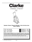
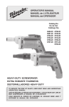
Which
Bulb
Burns
Brighter?
One is a 60-watt
bulb and the other a
100-watt bulb, and they
are connected in an
electric circuit.
➥ Look at the text
on page 541 for
the answer.
CHAPTER
23
Series and
Parallel
Circuits
our desk needs to be well lit. You have a 100-watt lightbulb
and a 60-watt lightbulb available for your desk lamp.
Which of the two lightbulbs would you choose? You know
a watt is a unit of power, so you might expect that a 100-watt
lightbulb would always produce more light than a 60-watt bulb.
But would it?
You’re shopping for a string of holiday lights for a party. You
find a string of pumpkin lights with a tag that reads “If one goes
out, the rest stay lit.” Why is this important? How are the lights
connected to each other and the power source to make sure that
the rest stay lit?
Does the type of electric circuit that connects the bulb make a
difference? Suppose the lightbulbs are in a circuit unlike the parallel circuit that normally connects lightbulbs in your home. For
example, in the photo at the left, the bulbs are connected in
series. Does that make a difference? Can you figure out why? To
answer these questions, you need to know how a series circuit differs from a parallel circuit.
In Chapter 22, you studied circuits that had one source of electric energy, for example, a battery and one device such as a motor
or a lamp that converted the electric energy to another form. But
circuits can be much more versatile than that. In this chapter,
you’ll explore several ways in which devices may be connected in
electric circuits. By the end of this chapter, you’ll have no trouble
deciding which of the two bulbs at the left is brighter and why the
rest of the bulbs stay lit.
Y
WHAT YOU’LL LEARN
•
•
You will distinguish between
parallel and series circuits
and series-parallel combinations and solve problems
dealing with them.
You will explain the function
of fuses, circuit breakers,
and ground fault interrupters,
and describe ammeters
and voltmeters.
WHY IT’S IMPORTANT
•
Electrical circuits are the
basis of every electrical
device, from electric lights to
microwave ovens to computers. Understanding circuits
helps you to use them, and
to use them safely.
PHYSICS
To find out more about electrical
circuits, visit the Glencoe Science
Web site at science.glencoe.com
531
23.1
Simple Circuits
I
OBJ ECTIVES
• Describe both a series
connection and a parallel
connection and state the
important characteristics
of each.
•
•
Calculate current, voltage
drops, and equivalent resistance for devices connected
in series and in parallel.
Describe a voltage divider
and solve problems
involving one.
FIGURE 23–1 No matter what
path the water of a river takes
down a mountain, the amount of
water and the drop in elevation
are the same.
532
Series and Parallel Circuits
f you have ever had the chance to explore rivers in
the mountains, such as the river shown below in
Figure 23–1, the following description will be
familiar. From their sources high in the mountains, rivers make their way
to the plains below. No matter what path they take, the change in elevation, from the mountaintop to the plain, is the same. Some rivers flow in a
single stream, tumbling through a series of rapids and over waterfalls.
Other rivers split into two or more streams as they flow over a waterfall or
through the rapids. Part of the river follows one path; other parts find different routes. But no matter how many paths the water takes, the total
amount of water flowing down the mountain is the same, and the vertical
drop from mountaintop to plain is the same distance.
Mountain rivers can serve as a model for electric circuits. The distance
the water drops is similar to potential difference. The amount of water
flowing through the river each second is similar to current. Narrow rapids
are like a large resistance. But what is similar to a battery or generator?
Just as in an electrical circuit, an energy source is needed to raise water
to the top of the mountain. As you learned in Earth science, the source of
energy is the sun. Solar energy evaporates water from lakes and seas and
forms clouds that release rain or snow to fall on the tops of mountains.
Think about the mountain river model as you read about the current in
electrical circuits.
Series Circuits
Pat, Chris, and Ali were connecting two identical lamps to a battery
as illustrated in Figure 23–2. Before making the final connection to the
battery, their teacher asked them to predict the brightness of the two
lamps. They knew that the brightness of a lamp depends on the current
flowing through it. Pat said that only the lamp closer to the + terminal
of the battery would light because all the current would be converted
into light. Chris said that the second lamp would light, but it would be
dimmer than the other one because some electrical energy would be
changed into thermal and light energy. Consequently, there would be
less electrical energy left for the second lamp. Ali said that both lamps
would be equally bright because current is a flow of charge, and because
the charge leaving the first lamp had nowhere else to go in the circuit
except through the second lamp, the current would be the same in the
two lamps. Who do you think is right?
If you consider the mountain river model for this circuit, you’ll see
that Ali is correct. Charge has only one path to follow. Recall from Chapter 20 that charge cannot be created or destroyed, so the same amount
of charge must leave a circuit as enters the circuit. This means that the
current is the same everywhere in the circuit. If you connect three
ammeters into a circuit as shown in Figure 23–3, they all have the same
value. A circuit such as this, in which all current travels through each
device, is called a series circuit.
But how could you answer Chris? If the current is the same, what
changes in the lamp to produce the thermal and light energy? Recall that
power, the rate at which electrical energy is converted, is represented by
P IV. Thus, if there is a potential difference or voltage drop across the
lamp, then electrical energy is being converted into another form. The
resistance of the lamp is defined as R V/I. Thus, the potential difference, also called the voltage drop, is V IR.
+
–
FIGURE 23–2 What is your
prediction about the brightness
of the two lightbulbs?
What is the current in the series circuit? From the river model,
you know that the sum of the drops in height at each rapid is equal to
the total drop from the top of the mountain to sea level. In the electrical circuit, the increase in voltage provided by the generator or other
energy source, Vsource, is equal to the sum of voltage drops across the
lamps A and B.
Vsource VA VB
Because the current, I, through the lamps is the same, VA IRA and
VB IRB. Therefore, Vsource IRA IRB or Vsource I(RA RB).
The current through the circuit is represented by the following.
Vsource
I
RA RB
This equation applies to any number of resistances in series, not just
two. The same current would exist with a single resistor, R, that has a
RA
+
–
Vsource
RB
FIGURE 23–3 The ammeters
show that in a series circuit the
current is the same everywhere.
23.1 Simple Circuits
533
F.Y.I.
Henry Cavendish used the
direct approach to measure
the strength of an electric
current. Lacking the
appropriate instruments,
he instead shocked himself
with the current and then
estimated the pain.
resistance equal to the sum of the resistances of the two lamps. Such a
resistance is called the equivalent resistance of the circuit. For resistors
in series, the equivalent resistance is the sum of all the individual
resistances.
Equivalent Resistance for Resistors in Series
R RA RB . . .
Notice that the equivalent resistance is larger than any single resistance. Therefore, if the battery voltage doesn’t change, adding more
devices in series always decreases the current. To find the current, I,
through a series circuit, first calculate the equivalent resistance, R, and
then use the following equation to calculate I.
Current
Vsource
I
R
Practice Problems
Pocket Lab
Series Resistance
Hook up a power supply, a
resistor, and an ammeter in a
series circuit. Predict what will
happen to the current in the
circuit when a second, identical
resistor is added in series to the
circuit. Predict the new currents
when the circuit contains three
and four resistors in series.
Explain your prediction. Try it.
Analyze and Conclude Make
a data table to show your
results. Briefly explain your
results. (Hint: Include the idea
of resistance.)
534
Series and Parallel Circuits
1. Three 20- resistors are connected in series across a 120-V
generator. What is the equivalent resistance of the circuit?
What is the current in the circuit?
2. A 10- resistor, a 15- resistor, and a 5- resistor are connected
in series across a 90-V battery. What is the equivalent resistance
of the circuit? What is the current in the circuit?
3. Consider a 9-V battery in a circuit with three resistors connected
in series.
a. If the resistance of one of the resistors increases, how will the
series resistance change?
b. What will happen to the current?
c. Will there be any change in the battery voltage?
4. A string of holiday lights has ten bulbs with equal resistances
connected in series. When the string of lights is connected to a
120-V outlet, the current through the bulbs is 0.06 A.
a. What is the equivalent resistance of the circuit?
b. What is the resistance of each bulb?
5. Calculate the voltage drops across the three resistors in
problem 2, and check to see that their sum equals the
voltage of the battery.
Voltage drops in a series circuit In any circuit, the net change in
potential as current moves through it must be zero. This is because the
electrical energy source in the circuit, the battery or generator, raises the
potential. As current passes through the resistors, the potential drops an
amount equal to the increase, and, therefore, the net change is zero.
The potential drop across each resistor in a series circuit can be calculated by rearranging the equation that defines resistance, R V/I, to
solve for V, V IR. First, find the equivalent resistance, R, in the circuit
by calculating the sum of all the individual resistances. Then, to find the
current, which is the same everywhere in the circuit, use the equivalent
resistance and the equation I V/R, where V is the potential drop. Having determined the current in the circuit, multiply I by the resistance of
the individual resistor to find the potential drop across that resistor.
An important application of series resistors is the voltage divider. A
voltage divider is a series circuit used to produce a voltage source of
desired magnitude from a higher-voltage battery. Suppose you have a 9V battery but need a 5-V potential source. A voltage divider can supply
this voltage. Consider the circuit shown in Figure 23–4. Two resistors,
RA and RB, are connected in series across a battery of magnitude V. The
equivalent resistance of the circuit is R RA RB. The current, I, is represented by the following equation.
V
V
I R
RA RB
RA
+
I
V
–
RB
VB
FIGURE 23–4 The values of RA
and RB are chosen such that the
voltage drop across RB is the
desired voltage.
The desired voltage, 5 V, is the voltage drop, VB, across resistor RB.
VB IRB.
I is replaced by the preceding equation.
V
VB IRB RB
RA RB
The Inverse Key
VRB
VB RA RB
Voltage dividers are often used with sensors such as photoresistors.
The resistance of a photoresistor depends upon the amount of light that
strikes it. Photoresistors are made of semiconductors such as silicon,
selenium, and cadmium sulfide. A typical photoresistor can have a resistance of 400 when light strikes it, but 400 000 when in the dark.
The output voltage of a voltage divider that uses a photoresistor
depends upon the amount of light striking the photoresistor sensor.
This circuit can be used as a light meter, such as the one in Figure 23–5.
In this device, an electronic circuit detects the potential difference and
converts it to a measurement of illuminance that can be read on the
digital display.
Amplified
Voltmeter
Because multiplication is the
inverse of division, you can use
the inverse key, 1/x, to perform
calculation without having to
reenter numbers.
(9 V)(500 )
400 500 Keys
Display
400
1/x
9
500
900
1.11 . . . 03
500
5
Answer 5 V
Sensitivity adjustment
(potentiometer)
Dry
cells
Light
Photoresister sensor
FIGURE 23–5 The output voltage
of this voltage divider depends
upon the amount of light striking
the photoresistor sensor. This is
the basis for the light meter
shown at left.
23.1 Simple Circuits
535
Example Problem
Voltage Drops in a Series Circuit
Two resistors, 47.0- and 82.0-, are connected in series across
a 45.0-V battery.
a. What is the current in the circuit?
b. What is the voltage drop across each resistor?
c. The 47.0- resistor is replaced by a 39.0- resistor. Will the current
increase, decrease, or remain the same?
d. What will happen to the voltage drop across the 82.0- resistor?
Sketch the Problem
• Draw a schematic of the circuit.
• Include an ammeter and voltmeters.
A
Calculate Your Answer
Known:
Unknown:
Vsource 45.0 V
I?
RA 47.0 VA ?
RB 82.0 VB ?
+
RA
V
VA
–
RB
VB
effects of changing RA
Strategy:
Calculations:
a. To determine the current, first find the
equivalent resistance.
R RA RB
Vsource
Vsource
I R
RA RB
45.0 V
I 0.349 47.0 82.0 b. Use V IR for each resistor.
VA IRA (0.349)(47.0 ) 16.4 V
VB IRB (0.349)(82.0 ) 28.6 V
c. Calculate current again using RA as 39.0 .
Vsource
45.0 V
0.372 I
RA RB
39.0 82.0 The current will increase.
d. Determine new voltage drop.
VB IRB (0.372)(82.0 ) 30.5 V
The voltage will increase.
Check Your Answer
• Are the units correct? Current, A V/, voltage, V A.
• Is the magnitude realistic? Numerically, R > V, so I < 1.
R decreases so I increases. VB changes because it depends on I.
536
Series and Parallel Circuits
Example Problem
Voltage Divider
A 9.0-V battery and two resistors, 400 and 500 , are connected
as a voltage divider. What is the voltage across the 500- resistor?
I
Sketch the Problem
+
• Draw the battery and resistors in a series circuit.
–
Calculate Your Answer
Known:
Strategy:
Vsource 9.0 V
Write the expression for the
current through the circuit.
RA 400 RB
VB
V
Calculations:
Vsource
I R
R RA RB
RB 500 Determine equivalent
resistance, R.
Unknown:
Use voltage drop equation to
determine VB.
VB ?
RA
(Vsource)(RB)
VB IRB RA RB
(9.0 V)(500 )
VB 5 V
400 500 Check Your Answer
• Are the units correct? V V /.
• Is the magnitude realistic? The voltage drop is less than the battery
voltage. Because 500 is more than half of the equivalent resistance,
the voltage drop is more than half the battery voltage.
Practice Problems
6. A 20.0- resistor and a 30.0- resistor are connected in series
and placed across a 120-V potential difference.
a. What is the equivalent resistance of the circuit?
b. What is the current in the circuit?
c. What is the voltage drop across each resistor?
d. What is the voltage drop across the two resistors together?
7. Three resistors of 3.0 k, 5.0 k, and 4.0 k are connected in
series across a 12-V battery.
a. What is the equivalent resistance?
b. What is the current through the resistors?
c. What is the voltage drop across each resistor?
d. Find the total voltage drop across the three resistors.
F.Y.I.
The largest voltages in your
home are in your television
set, where 15 000 V to
20 000 V are common.
The largest currents are
likely to be the 40 A in an
electric range.
Continued on next page
23.1 Simple Circuits
537
RC
RB
RA
Generator
FIGURE 23–6 The parallel paths
for current in this diagram are
analogous to the paths that a
river may take down the
mountain.
8. A photoresistor is used in a voltage divider as RB. V 9.0 V and
RA 500 .
a. What is the output voltage, VB, across RB, when a bright light
strikes the photoresistor and RB 475 ?
b. When the light is dim, RB 4.0 k. What is VB?
c. When the photoresistor is in total darkness, RB 0.40 M
(0.40 106 ). What is VB?
9. A student makes a voltage divider from a 45-V battery, a 475-k
(475 103 ) resistor, and a 235-k resistor. The output is
measured across the smaller resistor. What is the voltage?
Parallel Circuits
Look at the circuit shown in Figure 23–6. How many current paths
are there? The current from the generator can go through any of the three
resistors. A circuit in which there are several current paths is called a
parallel circuit. The three resistors are connected in parallel; both ends
of the three paths are connected together. In the mountain river model
for circuits, such a circuit is illustrated by three paths for the water over a
waterfall. Some paths may have a large flow of water, others a small flow.
The sum of the flows, however, is equal to the total flow of water over the
falls. In addition, it doesn’t matter which channel the water flows
through because the drop in height is the same. Similarly, in a parallel
electrical circuit, the total current is the sum of the currents through each
path, and the potential difference across each path is the same.
What is the current through each resistor? It depends upon the individual resistance. For example, in Figure 23–7, the potential difference
across each resistor is 120 V. The current through a resistor is given by
I V/R, so you can calculate the current through the 24- resistor as
I (120V)/(24 ) 5 A. Calculate the currents through the other two
resistors. The total current through the generator is the sum of the currents through the three paths, in this case, 38 A.
What would happen if the 6- resistor were removed from the circuit? Would the current through the 24- resistor change? That current
depends only upon the potential difference across it and its resistance,
and neither has changed, so the current is unchanged. The same is true
38 A
A
A
5A
A
13 A
A
20 A
120 V
FIGURE 23–7 In a parallel
circuit, the reciprocal of the total
resistance is equal to the sum of
the reciprocals of the individual
resistances.
538
Series and Parallel Circuits
24 V
120 V
9
V
120 V
6
120 V
V
for the current through the 9- resistor. The branches of a parallel
circuit are independent of each other. The total current through the generator, however, would change, and the sum of the currents in the
branches would then be 18 A.
How can you find the equivalent resistance of a parallel circuit? In
Figure 23–7, the total current through the generator is 38 A. A single
resistor that would have a 38-A current when 120 V were placed across
it would be represented by the following equation.
V
120 V
R 3.2 I
38 A
Notice that this resistance is smaller than that of any of the three resistors in parallel. Placing two or more resistors in parallel always decreases
the equivalent resistance of a circuit. The resistance decreases because
each new resistor provides an additional path for current, increasing the
total current while the potential difference remains unchanged.
To calculate the equivalent resistance of a parallel circuit, first note
that the total current is the sum of the currents through the branches. If
IA, IB, and IC are the currents through the branches and I is the total current, then I IA IB IC.
The potential difference across each resistor is the same, so the current through each resistor, for example, RA, can be found from IA V/RA. Therefore, this becomes the equation for the sum of the currents:
V
V
V
V
R
RA
RB
RC
Pocket Lab
Parallel Resistance
Hook up a power supply, a
resistor, and an ammeter in a
series circuit. Predict what will
happen to the current in the
circuit when a second, identical
resistor is added in parallel to
the first. Predict the new currents when the circuit contains
three and four resistors in
parallel. Explain your prediction.
Try it.
Analyze and Conclude Make
a data table to show your
results. Briefly explain your
results. (Hint: Include the idea
of resistance.)
Dividing both sides of the equation by V provides an equation for the
equivalent resistance of the three parallel resistors.
Equivalent Resistance for Resistors in Parallel
1
1
1
1
R
RA
RB
RC
This equation can be used for any number of resistors in parallel.
Example Problem
Equivalent Resistance and Current
in a Parallel Circuit
Three resistors, 60.0 , 30.0 , and 20.0 , are connected
in parallel across a 90.0-V battery.
a. Find the current through each branch of the circuit.
b. Find the equivalent resistance of the circuit.
c. Find the current through the battery.
Sketch the Problem
• Draw a schematic of the circuit.
• Include ammeters to show the paths of the currents.
A
A
IC
IB
IA
A
A
90.0 V
60.0 30.0 20.0 Continued on next page
23.1 Simple Circuits
539
Calculate Your Answer
Known:
Unknown:
RA 60.0 RC 20.0 IA ?
IC ? R ?
RB 30.0 V 90.0 V
IB ?
I?
Strategy:
a. The voltage across each resistor is the
V
same, so use I for each branch.
R
Calculations:
V
90.0 V
IA 1.50 A
RA
60.0 V
90.0 V
IB 3.00 A
RB
30.0 V
90.0 V
IC 4.50 A
RC
20.0 b. Use the equivalent resistance equation
for parallel circuits.
1
1
1
1
R
RA
RB
RC
1
1
1
1
0.100 1
R
60.0 30.0 20.0 R 10.0 V
c. Use I to find the total current.
R
V
90.0 V
I 9.00 A
R
10.0 Check Your Answer
• Are your units correct? Currents are in amps, resistances are in ohms.
• Do the signs make sense? All are positive, as they should be.
• Is the magnitude realistic? IA IB IC I
Practice Problems
10. Three 15- resistors are connected in parallel and placed across
a 30-V battery.
a. What is the equivalent resistance of the parallel circuit?
b. What is the current through the entire circuit?
c. What is the current through each branch of the circuit?
11. A 120.0- resistor, a 60.0- resistor, and a 40.0- resistor are
connected in parallel and placed across a 12.0-V battery.
a. What is the equivalent resistance of the parallel circuit?
b. What is the current through the entire circuit?
c. What is the current through each branch of the circuit?
12. Suppose one of the 15.0- resistors in problem 10 is replaced
by a 10.0- resistor.
a. Does the equivalent resistance change? If so, how?
540
Series and Parallel Circuits
b. Does the amount of current through the entire circuit change?
In what way?
c. Does the amount of current through the other
15.0- resistors change? In what way?
Now that you have learned about both parallel and series circuits,
you can analyze the brightness of the 60-W and 100-W lamps shown in
the photo at the beginning of this chapter. The brightness of a lightbulb
is proportional to the power dissipated by it. Used in the normal way,
each bulb would be connected across 120 V. Based on what you learned
in Chapter 22, the resistance of the 60-W bulb is higher than that of the
100-W bulb. But when the bulbs are connected in series, the current
through the two bulbs is the same, so P I2R. The higher-resistance
lamp, the 60-W lamp, now dissipates more power and glows brighter
than the 100-W lamp.
23.1
Which
Bulb Burns
Brighter?
➥ Answers question from
page 530.
Section Review
1. Are car headlights connected in series
or parallel? Draw on your experience.
2. Lamp dimmers often contain variable
resistors.
a. Would a dimmer be hooked in
series or in parallel with the lamp
to be controlled? Why?
b. Should the resistance of the
dimmer be increased or decreased
to dim the lamp?
3. A switch is connected in series with a
75-W bulb to a source of 120 V.
resistors. Suppose a wire is added to
connect points A and B. Answer the
following questions, explaining your
reasoning.
a. What is the current through
the wire?
b. What happens to the current
through each resistor?
c. What happens to the current drawn
from the battery?
d. What happens to the potential
difference across each resistor?
a. What is the potential difference
across the switch when it is closed
or on?
R
b. What is the potential difference
across the switch when it is open,
or off? Explain.
4.
A
Figure 23–8 has four identical
B
R
Critical Thinking The circuit in
R
R
FIGURE 23–8
23.1 Simple Circuits
541
23.2
Applications of Circuits
Y
OBJ ECTIVES
• Explain how fuses, circuit
breakers, and ground-fault
interrupters protect household wiring.
•
Analyze combined seriesparallel circuits and calculate the equivalent resistance of such circuits.
•
State the important characteristics of voltmeters and
ammeters, and explain how
each is used in circuits.
ou have already learned some of the elements
of household wiring circuits. It’s important to
understand the requirements and limitations of
these systems. Above all, it is important to be aware
of the safety measures that must be practiced to prevent accidents.
Safety Devices
In an electric circuit, fuses and circuit breakers are switches that act as
safety devices. They prevent circuit overloads that can occur when too
many appliances are turned on at the same time or a short circuit occurs
in one appliance. When appliances are connected in parallel, each additional appliance placed in operation reduces the equivalent resistance in
the circuit and causes more current through the wires. The additional
current may produce enough thermal energy (P I2R) to melt insulation on the wires and cause a short circuit in the wires or even a fire.
A fuse is a short piece of metal that melts if too large a current passes
through it. The thickness of the metal to be used is determined by the
amount of current that can be safely handled by the circuit. Should there
be a larger current through the circuit, the fuse will melt and break the
circuit. A circuit breaker, shown in Figure 23–9, is an automatic switch
that opens when the current reaches some set value. If current greater
than the set value flows in the circuit, the circuit is overloaded. The circuit breaker will open and thereby stop all current.
A ground-fault interrupter is often required by law in electrical outlets in bathrooms and kitchens. Current follows a single path from the
power source into the electrical outlet and back to the source. Sometimes, when an appliance such as a hair dryer is used, the appliance or
user might touch a cold water pipe or a sink full of water and in this way
create another current path through the user. If a current as small as
5 mA should follow this path through a person, it could result in serious injury. The ground-fault interrupter contains an electronic circuit
On-off
reset switch handle
Switch
contacts
FIGURE 23–9 When too much
current flows through the
bimetallic strip, it will bend down
and release the latch. The handle
moves to the off position causing
the switch to open, and that
breaks the circuit.
542
Series and Parallel Circuits
Current out
to loads
Bimetallic strip
Latch
Circuit Breaker
Current in from
central switch
15 A fuse
120 V
that detects small differences in current caused by an extra current path
and opens the circuit, thereby preventing dangerous shocks.
Electric wiring in homes uses parallel circuits, such as the one diagrammed in Figure 23–10, so that the current in any one circuit does
not depend upon the current in the other circuits. The current in a
device that dissipates power, P, when connected to a voltage source, V, is
represented by I P/V. Suppose, that in the schematic diagram shown
in Figure 23–10, a 240-W television is plugged into a 120-V outlet. The
current that flows is represented by I (240 W)/(120 V) 2 A. Then, a
720-W curling iron is plugged in. The current through the curling iron
is I (720 W)/(120 V) 6 A. Finally, a 1440-W hair dryer is plugged
in. The current through the hair dryer is I (1440 W)/(120 V) 12 A.
The current through these three appliances can be found by considering them as resistors in a parallel circuit in which the current through
each appliance is independent of the others. The value of the resistance
is found by calculating the current the appliance draws and then using
the equation R V/I. The equivalent resistance of the three appliances is
1
1
1
1
1
R
10 20 60 6
R 6 .
The 15-A fuse is connected in series with the power source so the
entire current passes through it. The current through the fuse is
V
120 V
I 20 A.
R
6
The 20-A current exceeds the rating of the 15-A fuse, so that the fuse will
melt, or blow, cutting off current to the entire circuit.
A short circuit occurs when a circuit is formed that has a very low
resistance. The low resistance causes the current to be very large. If there
were no fuse or circuit breaker, such a large current could easily start a
fire. A short circuit can occur if the insulation on a lamp cord becomes
old and brittle. The two wires in the cord could accidentally touch. The
resistance of the wire might be only 0.010 . When placed across 120 V,
this resistance would result in the following current.
V
120 V
I 12 000 A
R
0.010 FIGURE 23–10 This parallel
wiring arrangement permits the
use of more than one appliance
simultaneously, but if all three
appliances are used at once, the
fuse could melt.
HELP WANTED
ELECTRICIAN
Electrical contractor needs
electricians who have successfully completed a 5-year
apprenticeship program conducted by a union or professional builder’s association.
You must be a high school
grad, be in good physical
condition, have excellent
dexterity and color vision,
and be willing to work when
and where there is work. You
will do all aspects of the job,
including reading blueprints,
dealing with all types of
wires, conduits, and equipment. Safety and quality
work must be your highest
priorities. For information
contact:
International Brotherhood of
Electrical Workers
1125 15th Street, N.W.
Washington, DC 20005
23.2 Applications of Circuits
543
RA 8 ⍀
RA 8 ⍀
VA
IA
RB
60 V
IB
30 ⍀
IC
RC
20 ⍀
=
R BC
12 ⍀
VP
=
R
20 ⍀
FIGURE 23–11 Use these diagrams
as you study the following Problem
Solving Strategy.
Such a current would cause a fuse or a circuit breaker to open the circuit
immediately, thereby preventing the wires from becoming hot enough
to start a fire.
Combined Series-Parallel Circuits
Have you ever noticed the light in your bathroom dim when you
turned on a hair dryer? The light and the hair dryer were connected in
parallel across 120 V. This means that the current through the lamp
should not have changed when you plugged in the dryer. Yet the light
dimmed, so the current must have changed. The dimming occurred
because the house wiring had a small resistance in series with the
parallel circuit. This is a combination series-parallel circuit. The following is a strategy for analyzing such circuits. Refer to Figure 23–11
which illustrates the procedure described in steps 1, 2, and 3 of the
Problem Solving Strategy.
Series-Parallel Circuits
1. Draw a schematic diagram of the circuit.
2. Find any parallel resistors. Resistors in parallel have separate
current paths. They must have the same potential differences
across them. Calculate the single equivalent resistance that
can replace them. Draw a new schematic using that resistor.
3. Are any resistors (including the equivalent resistor) now in
series? Resistors in series have one and only one current
path through them. Calculate a single new equivalent resistance that can replace them. Draw a new schematic diagram
using that resistor.
4. Repeat steps 2 and 3 until you can reduce the circuit to a single resistor. Find the total circuit current. Then go backwards
through the circuits to find the currents through and the
voltages across individual resistors.
544
Series and Parallel Circuits
Circuits
Problem
Suppose that three identical lamps are connected to the same power supply. Can a circuit be made such that one lamp is brighter
than the others and stays on if either of the
others is loosened in its socket?
Hypothesis
One lamp should be brighter than the other
two and remain at the same brightness when
either of the other two lamps is loosened in
its socket so that it goes out.
Possible Materials
power supply with variable voltage
wires with clips
3 identical lamps and sockets
Plan the Experiment
1. Sketch a series circuit and predict the
relative brightness of each lamp. Predict
what would happen to the other lamps
when one is loosened so that it goes out.
2. Sketch a parallel circuit and predict the
relative brightness of each lamp. Predict
what would happen to the other lamps
when one is loosened so that it goes out.
3. Draw a combination circuit. Label the
lamps A, B, and C. Would the bulbs have
the same brightness? Predict what would
happen to the other two lamps when each
lamp in turn is loosened so that it goes out.
4. Check the Plan Show your circuits and
predictions to your teacher before starting
to build the circuits.
5. When you have completed the lab, dispose
of or recycle appropriate materials. Put away
materials that can be reused.
Analyze and Conclude
1. Interpreting Data Did the series circuit
meet the requirements? Explain.
2. Interpreting Data Did the parallel circuit
meet either of the requirements? Explain.
3. Formulating Hypotheses Explain the
circuit that solved the problem in terms
of current.
4. Formulating Hypotheses Use the definition of resistance to explain why one
lamp was brighter and the other two were
equally dim.
5. Making Predictions Predict how the
voltages would compare when measured
across each lamp in the correct circuit.
6. Testing Conclusions Use a voltmeter to
check your prediction.
Apply
1. Can one wall switch control several lights
in the same room? Are the lamps in parallel or series? Are the switches in parallel
or series with the lamps? Explain.
23.2 Applications of Circuits
545
Example Problem
Series-Parallel Circuit
A hair dryer with a resistance of 12.0 and a lamp with a resistance
of 125 are connected in parallel to a 125-V source through a 1.50-
resistor in series.
a. Find the current through the lamp when the hair dryer is off.
b. Find the current when the hair dryer is on.
c. Explain why the lamp dims when the hair dryer is on.
Sketch the Problem
• Draw a diagram of the simple series circuit when the dryer is off.
• Draw the series-parallel circuit including the dryer and lamp.
• Replace RA and RB with a single equivalent resistance, RP.
Calculate Your Answer
Known:
RA 125 Unknown:
IA1 ?
RB 12.0 R?
RC 1.50 IA2 ?
Vsource 125 V I2 ?
RC
RC
RC
IA
RA
RA
RB
R
V
IA2
IA1
a. When the hair dryer is off, the circuit is a
simple series circuit.
Calculations:
V
125 V
IA1 0.988 A
RA RC
125 1.50 b. Find the equivalent resistance for
parallel circuit.
R RB
1
1
1
, so Rp A
Rp
RA
RB
RA RB
Strategy:
Find the equivalent resistance for
entire circuit.
R RB
R RC Rp RC A
RA RB
Use equivalent resistance to determine the
current when the hair dryer is on.
Vsource
125 V
1.00 101 A
IA2 R
12.5 c. The greater current when the hair dryer
is on means a greater voltage drop across
RC, which causes less voltage across RA.
A decrease in voltage means current
decreases, which is less power.
(125 )(12.0 )
R 1.50 12.5 125 12.0 VC IRC (1.00 101 A)(1.50 ) 15.0 V
VA Vsource VC 125 V 15.0 V
1.10 102 V
VA
1.10 102 V
0.880 A
IA RA
125 Current drops from 0.988 A to 0.880 A. Power, P I2R, is smaller, consequently the light dims.
546
Series and Parallel Circuits
Check Your Answer
• Are the units correct? Current is in amps, potential drops are in volts.
• Is the magnitude realistic? Decreased parallel resistance increases
the current, causing a voltage drop in the series resistor. This leaves
less voltage across the combination, so the current is smaller.
Pocket Lab
Ammeter Resistance
Practice Problems
13. Two 60- resistors are connected in parallel. This parallel
arrangement is connected in series with a 30- resistor. The
combination is then placed across a 120-V battery.
a. Draw a diagram of the circuit.
b. What is the equivalent resistance of the parallel portion of
the circuit?
c. What single resistance could replace the three original resistors?
d. What is the current in the circuit?
e. What is the voltage drop across the 30- resistor?
f. What is the voltage drop across the parallel portion of
the circuit?
g. What is the current in each branch of the parallel portion of
the circuit?
Design an experiment using a
power supply, a voltmeter, an
ammeter, a resistor, and some
wires to determine the resistance of the ammeter. Make a
sketch of your setup and include
measurements and equations.
Communicating Results What
is the resistance of the ammeter?
Be prepared to present your
experiment to the class.
Ammeters and Voltmeters
An ammeter is used to measure the current in any branch or part of
a circuit. If, for example, you want to measure the current through a
resistor, you would place an ammeter in series with the resistor. This
requires opening a current path and inserting an ammeter. The use of an
ammeter should not change the current in the circuit you wish to measure. Because current would decrease if the ammeter increased the resistance in the circuit, the resistance of an ammeter should be as low as
possible. Figure 23–12 shows a real ammeter as an ideal, zero-resistance meter placed in series with a 0.01- resistor. The ammeter resistance is much smaller than the values of the resistors. The current
decrease would be from 1.0 A to 0.9995 A, too small to notice.
Another instrument, called a voltmeter, is used to measure the voltage
drop across some part of a circuit. To measure the potential drop across a
resistor, connect the voltmeter in parallel with the resistor. A voltmeter
should have a very high resistance so that it causes the smallest possible
change in currents or voltages in the circuit. Consider the circuit shown in
Figure 23–13. A typical inexpensive voltmeter consists of an ideal, zeroresistance meter in series with a 10-k resistor. When it is connected in
parallel with RB, the equivalent resistance of the combination is smaller
than RB alone. Thus, the total resistance of the circuit decreases, increasing
RA10.00 0.01 Ammeter
20 V
0.01 10 10 =20.01 RB10.00 FIGURE 23–12 An ammeter
measures current and so it is
always placed in series in a circuit.
23.2 Applications of Circuits
547
FIGURE 23–13 A laboratory
voltmeter such as this one measures potential difference. Voltmeters are placed in parallel.
10.00 RA
Voltmeter
20 V
10 k
10.00 RB
the current. RA has not changed, but the current through it has increased,
increasing the potential drop across it. The battery, however, holds the
potential drop across RA and RB constant. Thus, the potential drop across
RB must decrease. The result of connecting a voltmeter across a resistor is
to lower the potential drop across it. The higher the resistance of the voltmeter, the smaller the voltage change. Using a voltmeter with a 10 000-
resistance changes the voltage across RB from 10 V to 9.9975 V, too small
a change to detect. Modern electronic multimeters have even higher resistances, 107 , and so produce even smaller changes.
23.2
Section Review
1. Consider the circuit in Figure 23–14
made with identical bulbs.
a. Compare the brightness of the
three bulbs.
b. What happens to the brightness of
each bulb when bulb 1 is unscrewed
from its socket? What happens to the
three currents?
c. Bulb 1 is screwed in again and bulb 3 is
unscrewed. What happens to the brightness of each bulb? What happens to the
three currents?
d. What happens to the brightness of each
bulb if a wire is connected between
points B and C?
e. A fourth bulb is connected in parallel
with bulb 3 alone. What happens to
the brightness of each bulb?
548
Series and Parallel Circuits
2. Research and describe the connection
between the physics of circuits and
future careers.
3.
Critical Thinking In the circuit in
Figure 23–14, the wire at point C is
broken and a small resistor is inserted
in series with bulbs 2 and 3. What
happens to the brightness of the
two bulbs? Explain.
A
B
l3
A
l1
A
l2
A
1
2
C
V
FIGURE 23–14
3
Electric Switch
An electric switch is a device that is used to interrupt,
complete, or divert an electrical current in a circuit.
Switches are found on everything from hair dryers and
toaster ovens, to calculators and video games, to computers and airplane instrument panels. Some switches
are simple mechanical switches. In certain devices,
such as computers, however, mechanical switches are
too slow and are replaced by electronic switches made
from semiconducting materials.
Probably the most common type of switch is the
mechanical switch you use to operate the small appliances and lights in your home or school. The switch
shown below is a snap-action toggle switch typically
used to turn lights off and on.
Incoming current
Handle
4
1 The insulated handle of a snapaction toggle switch can be flipped
in either of two positions–off or on.
3
22. When the handle is in the off
position, as it is in this diagram,
metal contacts within the switch
are separated, interrupting the
path of the current.
1
2
5
3 When the handle is in the on posi-
Contacts
tion, the metal contacts, which are
linked by wires, come together to
complete the circuit.
4 One wire leads to a grounding location. Then if a problem occurs with
the wires or switch contacts, the current is routed to the ground, not to
the person touching the switch.
5 The switch casing is insulated, so
if a wire becomes loose or frayed
and touches the casing, current
will not flow.
Grounding
wire
OFF
Insulated casing
Wall plate
Thinking Critically
1. Circuit breakers are
automatic switches.
Explain why this is so.
2. Why must the contacts
in a switch be metal?
Why are switch handles
often plastic?
23.2 Applications of Circuits
549
CHAPTER
23 REVIEW
Summary
Key Terms
23.1 Simple Circuits
• The current is the same everywhere in
a simple series circuit.
• The equivalent resistance of a series
23.1
• series circuit
• equivalent
resistance
• voltage divider
• parallel circuit
•
•
23.2
• fuse
• circuit breaker
• ground-fault
interrupter
• short circuit
• combination
series-parallel
circuit
• ammeter
• voltmeter
•
•
•
•
circuit is the sum of the resistances of
its parts.
The sum of the voltage drops across
resistors in series is equal to the
potential difference applied across
the combination.
A voltage divider is a series circuit used
to produce a voltage source from a
higher-voltage battery.
The voltage drops across all branches
of a parallel circuit are the same.
In a parallel circuit, the total current
is equal to the sum of the currents in
the branches.
The reciprocal of the equivalent resistance of parallel resistors is equal to
the sum of the reciprocals of the individual resistances.
If any branch of a parallel circuit is
opened, there is no current in that
branch. The current
in the other branches
is unchanged.
23.2 Applications of Circuits
• A fuse or circuit breaker, placed in series
with appliances, creates an open circuit
when dangerously high currents flow.
• A complex circuit is often a combination of series and parallel branches.
Any parallel branch is first reduced to a
single equivalent resistance. Then any
resistors in series are replaced by a single resistance.
• An ammeter is used to measure the current in a branch or part of a circuit. An
ammeter always has a low resistance
and is connected in series.
• A voltmeter measures the potential difference (voltage) across any part or
combination of parts of a circuit. A
voltmeter always has a high resistance
and is connected in parallel with the
part of the circuit being measured.
Key Equations
23.1
R RA RB . . .
Vsource
I
R
1
1
1
1
R
RA
RB
RC
Reviewing Concepts
Section 23.1
1. Why is it frustrating when one bulb
burns out on a string of holiday tree
lights connected in series?
2. Why does the equivalent resistance
decrease as more resistors are added
to a parallel circuit?
3. Several resistors with different
values are connected in parallel.
550
Series and Parallel Circuits
How do the values of the individual
resistors compare with the equivalent
resistance?
4. Why is household wiring done in
parallel instead of in series?
5. Why is there a difference in total
resistance between three 60- resistors connected in series and three
60- resistors connected in parallel?
CHAPTER 23 REVIEW
6. Compare the amount of current entering a
junction in a parallel circuit with that leaving
the junction. Note: A junction is a point where
three or more conductors are joined.
Section 23.2
7. Explain the function of a fuse in an
electric circuit.
8. What is a short circuit? Why is a short circuit
dangerous?
9. Why does an ammeter have a very low
resistance?
10. Why does a voltmeter have a very high
resistance?
11. How does the way in which an ammeter is connected in a circuit differ from the way a voltmeter is connected?
Applying Concepts
12. What happens to the current in the other two
lamps if one lamp in a three-lamp series circuit
burns out?
13. Suppose that in the voltage divider in
Figure 23–4, the resistor RA is made to be a
variable resistor. What happens to the voltage
output, VB, of the voltage divider if the resistance of the variable resistor is increased?
14. Circuit A contains three 60- resistors in series.
Circuit B contains three 60- resistors in parallel. How does the current in the second 60-
resistor change if a switch cuts off the current
to the first 60- resistor in
a. circuit A?
b. circuit B?
15. What happens to the current in the other two
lamps if one lamp in a three-lamp parallel circuit burns out?
16. An engineer needs a 10- resistor and a 15-
resistor. But there are only 30- resistors in
stock. Must new resistors be purchased?
Explain.
17. If you have a 6-V battery and many 1.5-V bulbs,
how could you connect them so that they
light but do not have more than 1.5 V across
each bulb?
18. Two lamps have different resistances, one larger
than the other.
a. If they are connected in parallel, which is
brighter (dissipates more power)?
b. When connected in series, which is brighter?
19. For each of the following, write the form of
circuit that applies: series or parallel.
a. The current is the same throughout.
b. The total resistance is equal to the sum of
the individual resistances.
c. The voltage drop is the same across each
resistor.
d. The voltage drop is proportional to the
resistance.
e. Adding a resistor decreases the total
resistance.
f. Adding a resistor increases the total
resistance.
g. If the current through one resistor goes to
zero, there is no current in the entire circuit.
h. If the current through one resistor goes to
zero, the current through all other resistors
remains the same.
i. This form is suitable for house wiring.
20. Why is it dangerous to replace a 15-A fuse in a
circuit with a fuse of 30 A?
Problems
Section 23.1
21. A 20.0- lamp and a 5.0- lamp are connected
in series and placed across a potential difference of 50.0 V. What is
a. the equivalent resistance of the circuit?
b. the current in the circuit?
c. the voltage drop across each lamp?
d. the power dissipated in each lamp?
22. The load across a battery consists of two resistors, with values of 15 and 45 , connected
in series.
a. What is the total resistance of the load?
b. What is the voltage of the battery if the current in the circuit is 0.10 A?
23. A lamp having a resistance of 10.0 is connected across a 15-V battery.
a. What is the current through the lamp?
b. What resistance must be connected in series
with the lamp to reduce the current to
0.50 A?
Chapter 23 Review
551
CHAPTER 23 REVIEW
552
Series and Parallel Circuits
a. Find the resistance of the television.
b. The television and 2.5- wires connecting
the outlet to the fuse form a series circuit
that works like a voltage divider. Find the
voltage drop across the television.
c. A 12- hair dryer is plugged into the same
outlet. Find the equivalent resistance of the
two appliances.
d. Find the voltage drop across the television
and hair dryer. The lower voltage explains
why the television picture sometimes shrinks
when another appliance is turned on.
Section 23.2
32. A circuit contains six 240- lamps (60-W bulbs)
and a 10.0- heater connected in parallel. The
voltage across the circuit is 120 V. What is the
current in the circuit
a. when four lamps are turned on?
b. when all lamps are on?
c. when six lamps and the heater are operating?
33. If the circuit in problem 32 has a fuse rated at
12 A, will the fuse melt if everything is on?
34. Determine the reading of each ammeter and
each voltmeter in Figure 23–15.
35. Determine the power used by each resistance
shown in Figure 23–15.
V1
30 Al 1
30 A
10 30 24. A string of 18 identical holiday tree lights is
connected in series to a 120-V source. The
string dissipates 64.0 W.
a. What is the equivalent resistance of the
light string?
b. What is the resistance of a single light?
c. What power is dissipated by each lamp?
25. One of the bulbs in problem 24 burns out.
The lamp has a wire that shorts out the lamp
filament when it burns out. This drops the
resistance of the lamp to zero.
a. What is the resistance of the light string now?
b. Find the power dissipated by the string.
c. Did the power go up or down when a bulb
burned out?
26. A 75.0-W bulb is connected to a 120-V source.
a. What is the current through the bulb?
b. What is the resistance of the bulb?
c. A lamp dimmer puts a resistance in series
with the bulb. What resistance would be
needed to reduce the current to 0.300 A?
27. In problem 26, you found the resistance of a
lamp and a dimmer resistor.
a. Assuming that the resistances are constant,
find the voltage drops across the lamp and
the resistor.
b. Find the power dissipated by the lamp.
c. Find the power dissipated by the dimmer
resistor.
28. A 16.0- and a 20.0- resistor are connected in
parallel. A difference in potential of 40.0 V is
applied to the combination.
a. Compute the equivalent resistance of the
parallel circuit.
b. What is the current in the circuit?
c. How large is the current through the
16.0- resistor?
29. Amy needs 5.0 V for some integrated circuit
experiments. She uses a 6.0-V battery and two
resistors to make a voltage divider. One resistor
is 330 . She decides to make the other resistor
smaller. What value should it have?
30. Pete is designing a voltage divider using a
12.0-V battery and a 100.0- resistor as RB.
What resistor should be used as RA if the
output voltage across RB is to be 4.00 V?
31. A typical television dissipates 275 W when it is
plugged into a 120-V outlet.
l2
V2
V3
45.0 V
FIGURE 23–15
36. During a laboratory exercise, you are supplied
with a battery of potential difference V, two
heating elements of low resistance that can be
placed in water, an ammeter of very small resistance, a voltmeter of extremely high resistance,
wires of negligible resistance, a beaker that is
well insulated and has negligible heat capacity,
and 100.0 g of water at 25˚C.
a. By means of a diagram and standard symbols,
show how these components should be connected to heat the water as rapidly as possible.
CHAPTER 23 REVIEW
b. If the voltmeter reading holds steady at
50.0 V and the ammeter reading holds
steady at 5.0 A, estimate the time in seconds
required to completely vaporize the water in
the beaker. Use 4200 J/kg˚C as the specific
heat of water and 2.3 106 J/kg as the heat
of vaporization of water.
37. A typical home circuit is shown in Figure 23–16.
The lead lines to the kitchen lamp each has a
very low resistance of 0.25 . The lamp has a
resistance of 240.0 . Although it is a parallel
circuit, the lead lines are in series with each of
the components of the circuit.
0.25 Kitchen light
Power saw
240 0.25 Switch box 120 V
Wall outlets
Critical Thinking Problems
39. A 50-200-250-W three-way bulb has three terminals on its base. Sketch how these terminals
could be connected inside the bulb to provide
the three brightnesses. Explain how to connect
120 V across two terminals at a time to obtain
a low, medium, and high level of brightness.
40. Batteries consist of an ideal source of potential
difference in series with a small resistance. The
electrical energy of the battery is produced by
chemical reactions that occur in the battery.
However, these reactions also result in a small
resistance that, unfortunately, cannot be completely eliminated. A flashlight contains two
batteries in series. Each has a potential difference of 1.50 V and an internal resistance of
0.200 . The bulb has a resistance of 22.0 .
a. What is the current through the bulb?
b. How much power does the bulb dissipate?
c. How much greater would the power be if the
batteries had no internal resistance?
FIGURE 23–16
a. Compute the equivalent resistance of the circuit consisting of just the light and the lead
lines to and from the light.
b. Find the current to the bulb.
c. Find the power dissipated in the bulb.
38. A power saw is operated by an electric motor.
When electric motors are first turned on, they
have a very low resistance. Suppose that a
kitchen light in problem 37 is on and a power
saw is turned on. The saw and lead lines have
an initial total resistance of 6.0 .
a. Compute the equivalent resistance of the
light-saw parallel circuit.
b. What is the total current flowing in the circuit?
c. What is the total voltage drop across the
two leads to the light?
d. What voltage remains to operate the light?
Will this cause the light to dim temporarily?
Extra Practice For more
practice solving problems, go
to Extra Practice Problems,
Appendix B.
Going Further
Using What You’ve Learned An ohmmeter is
made by connecting a 6.0-V battery in series with
an adjustable resistor and an ideal ammeter. The
ammeter deflects full-scale with a current of
1.0 mA. The two leads are touched together and
the resistance is adjusted so that 1.0 mA flows.
a. What is the resistance of the adjustable resistor?
b. The leads are now connected to an unknown
resistance. What resistance would produce a current of half-scale, 0.50 mA?
c. What resistance would produce a reading of
quarter-scale, 0.25 mA?
d. What resistance would produce a reading of
three-quarters-scale, 0.75 mA?
PHYSICS
To review content, do the
interactive quizzes on the
Glencoe Science Web site at
science.glencoe.com
Chapter 23 Review
553