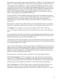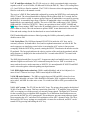
1
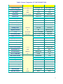
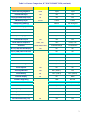
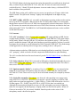
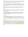
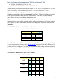
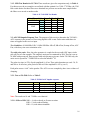
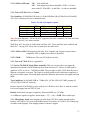
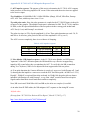
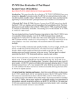
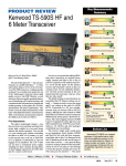
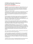
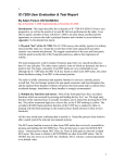
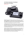
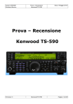
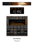
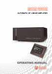
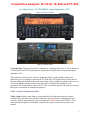
Competitive Analysis: IC-7410, TS-590 and FT-950 by Adam Farson, VA7OJ/AB4OJ. August/September, 2012. Figure 1: Kenwood TS-590. Figure 2: Yaesu FT-950. 1: Introduction. This report describes a comparative evaluation of the Icom IC-7410, Kenwood TS-590S and Yaesu FT-950 performed in my ham-shack and RF lab over the period AugustSeptember 2012. The document is in three parts: a feature comparison table covering all three transceivers, followed by on-air evaluation reports on the TS-590S and FT-950 and finally by the results of lab tests conducted on the Kenwood and Yaesu radios. Only an NPR (noise-power ratio) test, an AGC/noise-blanker impulse-response test and a test for IF notch filter anomalies were performed. The results of these tests on the IC-7410, as performed prior to the period covered by this report, are included for comparison purposes. PART 1: Feature Comparison Table. Tables 1 and 1a list the main features as provided in each of the three transceivers under consideration. Each table entry indicates briefly how the listed feature is implemented in its respective radio. Explanations are given as needed in the Notes at the foot of Table 1a. For a more detailed description of each radio’s listed features, please consult the respective user manual. 1 Table 1: Feature Comparison, IC-7410/TS-590S/FT-950 Feature IC-7410 TS-590S FT-950 Frequency Range 10 HF bands + 6m 10 HF bands + 6m 10 HF bands + 6m General Coverage RX Yes Yes Yes RF Output 100W 100W 100W Display Size 130 mm diagonal 180x32 mm 200x35 mm Display Type Mono LCD. Mono LCD Vacuum Fluorescent Backlight Type CCFL LED (Amber or Green) None Meter Type On-Screen On-Screen On-Screen Spectrum Scope Simple No DMU reqd. Power Supply External External External Primary Power 13.8V DC 13.8V DC 13.8V DC Digital Preselector No No Optional µ-Tuner 1st IF 64.455 MHz 11.3741 or 73.095 MHz 69.45 MHz 1st IF (Roofing) Filter 15/6/3 kHz2 2.7/0.51 or 15/6/2.7 kHz 15/6/3 kHz IF Stages (Conversions) 2 21 or3 3 Image Rejection Mixer Yes No No DSP IF BW Adjustment BW & Twin PBT Hi/Lo Cut & Width3 Shift/Width IF Filter Config. Display Shift Icon/BW Value Shift/Width Graphic Shift/Width Graphics DSP IF Filter Shape Factors Sharp/Soft/BPF Fixed Fixed DSP IF Filter Defaults 1, 2, 3 A, B NORM, NAR Digital Audio I/O USB USB None PC Connectivity USB/CI-V USB/RS-232 RS-232 DSP IF CONTOUR No RX EQ Yes Manual Notch Width WIDE/MID/NAR WIDE/NORM Fixed Tracking IF Notch Manual only Yes No Auto Notch (post-AGC) Suppresses 3 tones DNF (Beat Cancel) DNF (Beat Cancel) Noise Reduction Variable DSP NR DSP NR1/NR2 DNR: 15 values Noise Blanker Type DSP Analogue NB1, DSP NB2 DSP CW Audio Peak Filter No No Yes CW Tuning Aid No Auto Zero Beat Tuning offset scale CW Pitch Control Knob Menu Menu 2 Table 1a: Feature Comparison, IC-7410/TS-590S/FT-950 (continued) Feature IC-7410 TS-590S FT-950 Band Stacking Registers Triple Triple Triple Internal CW Keyer Yes Yes Yes Keying Speed/BKIN Delay Display No Yes Yes CW Memory Keyer 4 slots 4 slots 5 slots CW Spotting (Netting) Indirect Transmit Duty Cycle 100W, 100% RTTY: De-rate 25% RTTY: De-rate 50% Transmit Inhibit for QSK No No Yes Transmit Monitor Yes Yes Yes Amplifier Keying Line Relay/Low Level Relay/+12V Transistor switch External ALC Input Yes Yes Yes Band Data for Amplifiers Icom, THP THP Yaesu, THP Audio EQ TX/RX Bass/Treble TX/RX Bass/High5 TX Parametric RTTY (FSK) Decoder/Display Yes No No RTTY (FSK) Twin Peak Filter Yes No No Antenna Jacks 2 2 2 RX ANT IN Jack No Yes No Transverter Jack No Yes (DRV) No 4 Indirect 6 4 CW tuning aid Internal ATU Type Motorized capacitors Relay chain Relay chain Voice Squelch Yes No No Voice Synthesizer Yes OPT (VGS-1)7 Yes Voice Memory No OPT (VGS-1) OPT (DVS-6) External Display No No DMU Firmware Upgrading USB USB RS-232 Remote Control Software RS-BA1 ARHP-590, ARVP-10 PCC-950 (local PC only) 5 * 10 TCXO Standard OPT (SO-3) Standard Frequency Calibration Int. Cal. Marker CW Sidetone Ext. counter reqd. “My Bands” select No No Yes User-programmable keys None 2 PF keys Custom Switch (CS) 5167.5 kHz Alaska Emerg. Freq. No Yes Yes -7 3 Notes to Tables 1, 1a: 1. 2. 3. 4. 5. 6. 7. 160 – 15m bands only, excl. WARC bands. 6 & 3 kHz filters optional (FL-430, FL-431). SSB/AM/FM: Hi/Lo Cut. CW/FSK: Shift/Width. CW spotting possible by tuning received signal to same pitch as sidetone. EQ parameters preset, but configurable via ARCP-590 software. Morse code accessibility annunciator standard. 4-pin Molex socket for remote auto-couplers (e.g. AH-4) fitted. Part 2A: TS-590S “In the Shack” Evaluation Report. 2.1 TS-590S in the shack: I was able to spend a number of days with the TS-590S in my hamshack, and thus had the opportunity to exercise the radio’s principal features and evaluate its onair behavior. The firmware in the tested radio is at the current rev. level (1.06). 2.1.1. Connections and setup: First, I made up a cable with a 7-pin DIN plug at one end and four RCA jacks at the other. This enabled me to connect the PTT, ALC and F SET leads of my Yaesu Quadra amplifier to the correct pins of the TS-590S’s REMOTE socket. This cable, the station ground and the RF drive jumper, completed the hook-up to the amplifier. Operation with the Quadra is described here. Next, I connected the supplied hand mic, my straight key and the power supply (my IC-PS126). I then adjusted the drive power and ALC to level the system output at 1 kW in FSK mode. The station was now ready for on-air testing. 2.1.2. Physical “feel” of the TS-590S: The TS-590S is surprisingly compact and light for a 100W-class radio with an impressive array of features. It is 270W x 96H x 291D mm and weighs only 7.4 kg. Its compact size lends itself to semi-portable operation e.g. at Field Day, but its front panel and controls are sufficiently large to assure operating comfort. The overall appearance and layout of the front panel are similar to those of the earlier TS-570S. The TS-590S is built on a die-cast light-alloy “tub” chassis with sheet-steel clamshell covers finished in matte black. The front panel has the same finish. A carrying handle is fitted to the right side of the case, and a bail at the front of the bottom cover permits raising the front of the radio. The large (80 mm Ø) top-firing speaker is on the left side of the top cover. The overall fit and finish are of excellent quality, and all controls have a smooth tactile feel. 2.1.3. Controls and menus: The main tuning knob is medium-sized, and has a knurled Neoprene grip; it turns smoothly, without side-play. An adjustable dial brake is provided. The other five control knobs – NOTCH/SQL, HI/SHIFT-LO/WIDTH (equivalent to Twin PBT), RIT/XIT, MULTI/CH and AF/RF (Gain) are grouped in two columns on the right side of the front panel. (CW Pitch is a menu item.) The menus are easily navigable using the MENU and U/D/L/R arrow keys and the MULTI/CH knob. Pressing L/R or rotating the MULTI/CH knob selects the menu number, and pressing U/D changes the parameter value. When a menu is open, its easily-comprehensible descriptor scrolls across the screen. Two independent menu sets, Menu A and Menu B, can be stored to accommodate two different usage configurations or operators. 4 Other functions are accessed via front-panel keys; variables such as power output are adjustable by pressing their associated key (e.g. PWR) and rotating the MULTI/CH knob. I found the panel layout logical and easy to master. 2.1.4. Display: The rectangular LCD display, 180W x 32H mm, occupies most of the front-panel width. The displayed characters and icons are clear and legible. When accessed, menus are displayed as scrolling texts in plain English. Amber or green LED backlighting is selectable via menu. A curved bar-graph meter to the left of the frequency readout displays signal strength on receive. On transmit, power output is displayed. The METER key allows selection of ALC, SWR and compression scales (the latter when PROC is on).A bar-graph below the meter scales gives a visual indication of DSP IF filter low and high cutoff points. 2.1.5. Internal autotuner: The TS-590S employs a relay-chain antenna tuner which matches loads over a 3:1 VSWR range more rapidly than a tuner using motorized variable capacitors. It will also accept an external autotuner. The internal tuner is in the common (antenna) signal path. 2.1.6. USB interface: The TS-590S is fitted with a rear-panel USB “B” port. This allows direct connection to a laptop or any other PC via a standard USB “A-B” cable. The USB port carries rig-control data and TX/RX PCM baseband between the radio and the PC. As a result, the USB cable is the only radio/PC connection required. The TS-590S is firmware-upgradeable via the USB “B” port. Gone forever is the mess of cables, level converters and interface boxes! A Kenwood driver is required in the connected PC; this is downloadable from the Kenwood website. 2.1.7. IF and filter selections: The TS-590S employs a unique receiver architecture in which the front end routes CW, SSB, SSB-DATA and FSK (RTTY)signals in the 160m through 15m bands (excluding the WARC bands) to an inband 1 st IF (“down-conversion”) at 11.374 kHz. This permits the placement of high-quality crystal filters immediately after the 1st mixer for improved close-in dynamic performance. In all other frequency ranges and/or modes, the signal is routed to a high 1st IF at 73.095 MHz, which is translated to a 10.695 MHz 2 nd IF (“up-conversion”). The 11.374 or 10.695 MHz IF is then down-converted to the 24 kHz final (DSP) IF. This signalrouting process is transparent to the operator, but when a DSP IF bandwidth greater than 2.7 kHz is selected when the receiver is in the “down-conversion” mode, it switches to “up-conversion” and selects a wider 1st IF filter automatically. Two inband 1st IF filters (2.7 kHz and 500 Hz) and three high 1st-IF filters (15, 6 and 2.7 kHz) are fitted. The TS-590S’s firmware selects the appropriate filter for each band/mode combination. The receiver’s DSP IF filter bandwidth is adjusted by rotating the Hi/Lo Cut knobs in the voice modes (SSB, AM, FM). For CW and SSB-DATA, the Hi/Lo Cut controls become Shift/Width, and for FSK Shift is disabled. A large range of discrete cutoff frequency and shift/bandwidth values is available, but filter bandwidths are not continuously variable. The maximum SSB receive DSP filter width is 0 – 5000 Hz. There is no equivalent to Icom’s SOFT, SHARP and BPF shape-factor settings. Filter and mode settings for the last band used are stored with that band. 5 2.1.8. Notch filters: The DSP-based manual NOTCH and auto-tracking A-NOTCH are inside the AGC loop, and are extremely effective. The notch has 2 width settings; its stopband attenuation is at least 65 dB. The notch suppresses an interfering carrier before it can stimulate AGC action; it thus prevents swamping. The beat-cancel filters (BC1, BC2) are post-AGC. They suppress single and multiple tones, but strong undesired signals can still cause AGC action and swamp the receiver. BC is inoperative in CW and FSK modes, as are NOTCH and A-NOTCH on AM/FM. The NOTCH key toggles between manual Notch and A-NOTCH, and the BC key selects OffBC1-BC2. Status icons are displayed on the screen when these features are active. It should be noted that A-NOTCH is essentially the manual NOTCH with an auto-tracking function added. It can suppress only a single tone. 2.1.9. NR (noise reduction): There are two NR modes, NR1 for voice and NR2 for CW and digital modes. The NR1 and NR2 levels are adjustable via menu. (See 2.3, Concerns below.) The Kenwood literature (Ref. 1) describes NR1 as a spectral-subtraction process and NR2 as an auto-correlator (SSB) or line enhancer (CW, FSK) 2.1.10. NB (noise blanker): The NB key toggles between NB1 and NB2, whose levels are individually adjustable via menu. NB is disabled in FM mode. NB1 is an analogue pulse-gate type blanker which is optimized for use in conjunction with the narrow 1 st-IF filters (SSB and CW on bands utilizing the inband 1 st IF). NB2 is a DSP blanker which can often suppress noise events that “slip by” NB1. NB2 is quite effective in conjunction with NR. 2.1.11. AGC system: The TS-590S has dual AGC loops. The primary loop samples the digitized 24 kHz IF at the ADC output. This loop limits the IF signal power applied to the ADC input, thereby preventing ADC over-ranging even in the presence of extremely strong signals. The digital AGC detector for the secondary loop is within the DSP algorithm. Level indications from both detectors are processed in the DSP for AGC management. This architecture prevents strong adjacent signals from swamping the AGC, and allows full exploitation of the ADC’s dynamic range. The Slow (normal) and Fast AGC decay settings are customizable via menu for each mode, and AGC can be turned OFF via menu. 2.1.12. Receive and transmit audio menus: Transmitted bandwidth (low and high cutoff frequencies), RX and TX equalization and transmit compression, etc. are all configurable via menu. The widest SSB/AM transmit audio bandwidth setting is 10 – 3000 Hz. The transmit and receive equalization selections are preset to default values, but are customizable via the ARCP590 software in a PC connected to the TS-590S. 2.1.13. VFO/Memory management: The TS-590S offers VFO and memory management features similar to those of many other current HF+ transceivers: VFO/memory toggle and transfer, memory write/clear, Split, triple band-stacking registers, VFO A/B swap and equalize, Quick Memory (Memo Pad) etc. 2.2. Brief “on-air” report: After completing the lab tests, I installed the TS-590S in my shack and connected it to my Yaesu Quadra solid-state 1 kW amplifier and multi-band vertical antenna. The interface was straightforward; RF drive and a cable plugged into the TS-590S’s REMOTE socket to provide PTT, ALC and carrier request (for amplifier auto-tuning). Once I had set up the ALC for 1 kW system output, I was 100% QRV. 6 2.2.1. SSB: Using the supplied dynamic hand mic, I made several 20m SSB QSO’s with friends who are familiar with my voice and the sound of my signal. The universal consensus was that I “did not sound nearly as good” as I did on my normal station. With much assistance from the other stations, I was able to find a combination of transmit bandwidth, mic gain, compression and RF drive level to the amplifier which yielded satisfactory results at the distant end. Even then, my mic audio sounded ever so slightly “rough” and distorted in the TS-590S Monitor. A moderate amount of compression with mic gain (COMP IN) at 50% and TX EQ off or set to HB2 (high boost 2) appeared to yield the best results. I had to adjust the compression and RF power output very carefully to control ALC overshoot and avoid overdriving the amplifier (see 2.3, Concerns.) The default “Hard” compression profile sounded very harsh on the air; I changed it to “Soft” with more pleasing results. The internal autotuner found a match in less than 1 second, and was fairly quiet. I found the TS-590S’s menu system quite user-friendly and convenient. When a menu is opened up, the description of the menu item scrolls across the display in plain English. Two features on the TS-590S which appealed to me were the auto-tracking notch inside the AGC loop and the “High/Low Cut”, which is essentially the same as Icom’s Twin PBT. It is the sole method for setting receiver filter bandwidths. (There is no equivalent to Icom’s SHARP, SOFT and BPF filter shape factor settings.) The TS-590S has several fixed TX and RX audio equalizer selections: High Boost 1 & 2, Bass Boost 1 & 2, Formant Pass (correlation discrimination) and Conventional (TX, 3 dB preemphasis above 600 Hz) or Flat (RX). External software is required to implement a variable EQ. Without the external software, this is much less configurable than Icom’s TX and RX bass/treble equalization, TBW and selectable RX HPF/LPF, which can all be accessed from the radio’s front panel. When I put the noise blankers through their paces, I found that NB1 was not as effective against my local power-line hash and industrial noise sources as Icom’s DSP NB implementation. (I had set NB1 level to 5.) For NB1 level > 5, some distortion on SSB voice peaks was heard. NB2 was somewhat more effective against my local noise than NB1, although I found that it raised the receiver’s noise floor audibly. For this test run, NB2 level was set to 10. Still, overall I found SSB operation on the TS-590S quite comfortable, with good audio articulation on receive (and on transmit after some “tweaking”) and no significant listener fatigue. 2.2.2. CW: I held a 30-minute QSO with a station on 40m CW, using a straight key, QSK and semi-break-in. There was no evidence of “dit-clipping”. With Preamp off and NR1 on, no ringing was heard with IF filter BW ≥ 200 Hz. For 100 ≤ BW ≤ 200 Hz, slight ringing was evident; for 50 ≤ BW ≤ 100 Hz the ringing was more evident, but still not severe. Enabling the preamp did not significantly increase ringing. NR1 and NB1 were quite effective in reducing the band noise level, but given the narrow IF bandwidth the band noise was already quite low. 7 The TS-590S displays the keying speed (when using the internal keyer) and break-in drop-back delay, a feature not provided on the IC-7410. Also, the CW auto-zero (auto-tune) function worked effectively. I found CW pitch adjustment via memo rather clumsy; a dedicated PITCH knob would have been preferable. The QSK feature works well, with fast receiver recovery at speeds up to 30 wpm, which is the highest I tested. The QSK mode “thumps” slightly in the headphones at the higher keying speeds. 2.2.3. RTTY (FSK), AM, FM. As I was unable to find stations operating in these modes and am not set up for RTTY operation, I did not operate the TS-590S in these modes. It is noteworthy, though, that a narrower FM receive IF filter is not automatically selected when narrow FM is set up. By contrast, the transmit deviation and receive FM IF filter selections are linked in the Icom radios and in the FT-950. The SSB Hi/Lo Cut IF bandwidth adjustment feature is also available in AM and FM modes. 2.3. Concerns: 2.3.1. ALC overshoot: I observed severe ALC overshoot (RF output spiking) on SSB, but not on other modes. Initially, I set the Quadra ALC and the TS-590S PWR for 1 kW system output in FSK mode. When I selected USB, the TS-590S drove the Quadra to nearly 1.3 kW on voice peaks! I enabled the internal 3 dB pad in the Quadra to protect the amplifier, but later I was able to mitigate the overshoot by careful adjustment of Mic Gain and COMP OUT. The disadvantage of that approach was reduced peak-to-average ratio, resulting in lower “talk power”. A distant station recorded my SSB signal as received and played back a sound-clip. I observed ALC ‘pumping”, which occurred even with compression disabled and was quite disturbing. The ALC overshoot has been discussed extensively on the TS-590 Yahoo! Group, on eHam and elsewhere. 2.3.2. Noise reduction: When NR1 is activated in SSB mode with default bandwidth, the receive audio sounds watery and “rubbery”; there is a sort of burbling background sound. This effect is more severe when NR2 is selected. 2.3.3. Spurious signals (“birdies”): A number of low-level “birdies” were encountered when tuning the receiver across its frequency range, but only two of these fall into amateur bands: 1829 and 14137 kHz. These are at a very low level and would normally be swamped by antenna noise. 2.3.4. Notch filter anomalies: Microphony was observed when notching out a strong carrier using NOTCH or A-NOTCH. The receiver was tuned to a specific frequency in USB or LSB mode, and a test signal was applied at a +1 kHz (USB) or -1 kHz (LSB) offset and at a level of 50 dBm (approx. S9 + 20 dB). Using NOTCH or A-NOTCH, the tone was notched out. Although the measured notch depth was in spec (63 dB), microphony was noticed. When the radio case was tapped with the fingertips, a ringing sound was heard in the speaker. When AF Gain was increased to70%, the acoustic feedback from the speaker to the source of the microphony caused a howl in the speaker. 8 In addition, at frequencies below 10 MHz, a strong spurious tone at twice the frequency offset was heard in the speaker, e.g. 2 kHz for 1 kHz offset, and 1.4 kHz for 700 Hz offset. The higher the test signal level, the louder the tone. Part 2B: FT-950 “In the Shack” Evaluation Report. 2.4 FT-950 in the shack: I spent a few days with the FT-950 in my ham-shack, and thus had the opportunity to exercise the radio’s principal features and evaluate its on-air behavior. The firmware in the tested radio is at the current rev. level (CPU 1.16, EDSP 20.47). 2.4.1. Connections and setup: At first, I operated the FT-950 “barefoot” at 100W output. I connected the supplied hand mic, my straight key and the power supply (my IC-PS126). When the required CT-118 interface cable arrived, I connected the FT-950 to my Quadra amplifier via the cable. I then adjusted the drive power and ALC to level the system output at 1 kW in FSK mode. The station was now ready for on-air testing at full power. 2.4.2. Physical “feel” of the FT-950: The FT-950 has a fairly large footprint, but its case is quite low. It is 365W x 115H x 315D mm and weighs 9.8 kg. The FT-950 is built on a die-cast light-alloy “tub” chassis with sheet-steel clamshell covers in an attractive black crinkle finish. The front panel has a smooth matte black finish. A carrying handle is fitted to the right side of the case, and the front feet can be extended to raise the front of the radio. The large (90 mm Ø) top-firing speaker is on the left side of the top cover. The overall fit and finish are of excellent quality, and all controls have a smooth tactile feel. The detented SELECT knob has a firm, but not tight detent, and the front-panel keys have a positive snapaction. The rear apron of the chassis forms the rear panel, on which the various interface connectors are mounted. Connectors are spaced well apart to facilitate cabling. 2.4.3. Controls and menus: The solid brass main tuning knob is large (58 mm Ø) and heavy (185g). It has a knurled Neoprene grip and turns smoothly, without side-play. An adjustable dial brake is provided. Figure 3: Yaesu FT-950 showing main controls. 9 The controls are grouped around three main control knobs: TUNING (1), CLAR/VFO-B (2) and SELECT (3). In the operating mode, CLAR/VFO-B is used to adjust the clarifier (RIT/XIT), or VFO B in Split mode, and SELECT is rotated to adjust SHIFT/WIDTH (equivalent to Icom’s Twin PBT), NOTCH, CONTOUR (a variable audio bandpass/bandstop filter) or µ-TUNE (an optional RF preselector accessory. In MENU mode, SELECT brings up the required menu and CLAR/VFO-B adjusts its parameter value. TUNING can also be rotated to select a menu. MENU mode is entered by pressing and holding the MENU key. To save the new value and return to operating mode, press and hold the MENU key. Pressing the SELECT knob in MENU mode toggles between the menu number/group and the menu item descriptor, e,g, [001 AGC] [FST DLY] for Menu #001, AGC Group, Fast Delay. The menu parameter value is varied by rotating CLAR/VFO B. I found the menu symbols sufficiently cryptic to require that I consult the user manual whenever I wished to access the menu system. Many common variables such as NR level, RF power output and compression level, which are adjustable via front-panel controls on the Icom radios, are embedded in menus on the FT-950. 2.4.4. Display: The rectangular vacuum-fluorescent display (VFD), 200W x 30H mm, is recessed. The display is bright and legible, but the small feature-status icons can be difficult to read. The bar-graph meter to the left of the frequency readout displays signal strength on receive and power output on transmit. On transmit, power output, the METER key allows selection of ALC, SWR and compression scales (the latter when PROC is on). A small digital readout, and a bar-graph to its left, are located below the main frequency readout field. These display the clarifier offset graphically and numerically. The bar-graph also functions as a spotting (netting) aid in CW mode. Yaesu’s unique “block diagram” showing current front-end configuration and AGC selection is displayed to the top left of the frequency readout. Below it is a bar-graph matrix showing visual indications of current IF filter SHIFT/WIDTH, tunable IF NOTCH, CONTOUR and CW APF settings. To the left of the matrix are the designators for the matrix, and to the left of these are DNF (Auto-Notch) and DNR (NR) status icons. RF preamp choices are IPO (off), AMP 1 and AMP 2, selected by pushing the IPO key. 2.4.5. Internal autotuner: The FT-950 employs a relay-chain antenna tuner which matches loads over a 3:1 VSWR range more rapidly than a tuner using motorized variable capacitors. It will also accept an external Yaesu FC-40 autotuner. The internal tuner is in the transmit signal path only, where the Icom and Kenwood tuners are in the common (antenna) signal path. 2.4.6. CAT interface: The FT-950 is fitted with a rear-panel RS-232 (DB9) serial port. This allows direct connection to a PC COM port. This port is also configurable for firmware upgrading by setting a programming switch near the RS-232 socket. No USB port is provided. 10 2.4.7. IF and filter selections: The FT-950 receiver is a fairly conventional triple-conversion superhet, with IF’s at 69.45 MHz, 450 kHz and 30 kHz (the DSP IF). Three 1st-IF roofing filters (15, 6 and 3 kHz) are fitted as standard. The FT-950’s firmware selects the appropriate roofing filter for each mode, with manual override. The receiver’s DSP IF filter bandwidth is adjusted by pressing the WIDTH key and rotating the SELECT knob. The selected bandwidth is displayed in the readout field for 3 seconds; the bargraph displays relative width. A separate group of narrow IF bandwidths is accessed by pressing the NAR key. A reasonably large range of discrete IF bandwidth values is available, but filter bandwidths are not continuously variable. The receive DSP filter width range is 200 - 3000 Hz (SSB) and 100 - 2400 Hz (CW/RTTY). There is no equivalent to Icom’s SOFT, SHARP and BPF shape-factor settings. SHIFT moves the IF passband relative to virtual carrier. AM and FM filter widths are fixed, with wide and narrow options. SHIFT is non-functional in these modes. Filter and mode settings for the last band used are stored with that band. FM IF bandwidth and deviation are linked; pressing the NAR key alternately enables and disables narrow FM. 2.4.8. Notch filters: The DSP-based manual IF NOTCH is inside the AGC loop, and is extremely effective. Its bandwidth is fixed, and its stopband attenuation is at least 60 dB. The notch suppresses an interfering carrier before it can stimulate AGC action; it thus prevents swamping. With the NOTCH key pressed, rotating the SELECT knob tunes the notch across the IF passband. The bar-graph indicates the relative position of the notch in the passband, and the notch frequency is displayed in the readout field for 3 seconds when SELECT is rotated with NOTCH selected. The DNF (digital notch filter) is post-AGC. It suppresses single and multiple tones, but strong undesired signals can still cause AGC action and swamp the receiver. DNF is activated via menu, and can be active at the same time as NOTCH. It is non-adjustable.IF NOTCH and DNF can be activated together without degrading notch performance. 2.4.9. DNR (digital noise reduction): DNR is enabled/disabled, and its level adjusted, via menu. It has 15 discrete level steps. DNR is most helpful in SSB mode. 2.4.10. NB (noise blanker): The NB key toggles between NB1 and NB2, whose levels are individually adjustable via menu. NB is disabled in FM mode. NB1 is optimized for narrow noise pulses, and NB2 for wider noise events. To switch from NB1 to NB2, press and hold the NB key. 2.4.11. AGC system: The FT-950 has dual AGC loops. The primary loop samples the digitized 24 kHz IF at the ADC output. This loop controls the gain of the 1st IF amplifier, thus preventing ADC over-ranging even in the presence of extremely strong signals. The digital AGC detector for the secondary loop is within the DSP algorithm. Level indications from both detectors are processed in the DSP for AGC management. This architecture prevents strong adjacent signals from swamping the AGC, and allows full exploitation of the ADC’s dynamic range. The Slow, Mid and Fast AGC decay settings are customizable via menu for each mode, and AGC can be turned OFF by pressing and holding the AGC key. 11 2.4.12. Receive and transmit audio menus: Transmitted bandwidth TBW (low and high cutoff frequencies), RX and TX equalization and transmit compression, etc. are all configurable via menu. The widest SSB/AM transmit audio bandwidth setting is 10 – 3000 Hz. Unlike the Icom radios, the FT-950 does not offer separate low and high cutoff frequency settings. The FT-950 has two groups of 3-band parametric transmit audio equalizer selections, for compression off and on respectively. Equalization parameters and compression level are adjustable via menu. This equalizer feature offers greater transmit audio configurability than than Icom’s audio-management feature set; however, the Icom TX and RX bass/treble equalization, TBW and selectable RX HPF/LPF are much easier to administer. 2.4.13. VFO/Memory management: The FT-950 offers VFO and memory management features similar to those of many other current HF+ transceivers: VFO/memory toggle and transfer, memory write/clear, Split, Quick Split, triple band-stacking registers, VFO A/B swap and equalize, Quick Memory (Memo Pad) etc. 2.4.14. Band Stacking Registers: In addition to mode and filter selection, each of the 3 registers holds NB and tuner status for the stored frequency. This is a useful feature. The Icom radios do not store NB or tuner data for each stacked frequency. 2.4.15. CONTOUR: This feature, unique to Yaesu is a tunable, post-AGC IF peak or notch filter which inserts either a peak or notch in the IF passband. The boost/cut range is -40 to +20 dBm, and the peak/notch width is adjustable. These parameters are set up via menu. The Contour facility can be used to enhance the readability of a weak or noisy SSB signal, or to reduce listener fatigue. With the CONT key pressed, rotating the SELECT knob tunes the notch or peak across the IF passband. 2.4.16. APF (Audio Peak Filter): This is a narrow, post-demodulation DSP bandpass filter which enhances a single tone such as a CW signal, and improves its signal/noise ratio. The APF is activated by pressing and holding the CONT key, and is not tunable. An APF graphic shows in the bar-graph matrix when APF is active. APF is available only in CW mode. 2.5. Brief “on-air” report: After completing the lab tests, I installed the FT-950 in my shack and connected it to my Yaesu Quadra solid-state 1 kW amplifier and multi-band vertical antenna via the CT-118 interface cable. Once I had set up the ALC for 1 kW system output, I was 100% QRV. 2.5.1. SSB: Using the supplied MH-31 dynamic hand mic, I made several 20m SSB QSO’s with friends who are familiar with my voice and the sound of my signal. With some assistance from the other stations, I easily found a combination of transmit bandwidth, mic gain and compression which yielded good results at the distant end. Sound-clips of my transmissions sounded quite pleasant to my ear. About 6 dB of compression, with mic gain at 30% and TX EQ at default settings appeared to yield the best results. The transmit bandwidth was set to 100 – 3000 Hz. There was no trace of ALC overshoot. I found the FT-950’s menu system somewhat awkward to use, as discussed in Section 2.4.3 above. 12 The FT-950’s IF filter shape factors are fixed for each mode. There is no equivalent to Icom’s SHARP, SOFT and BPF filter shape factor settings. As I was using only the hand mic, I left all equalizer settings at default and adjusted only mic gain, TBW and compression level. Putting the noise blankers through their paces, I found that NB1 was not as effective against my local power-line hash and industrial noise sources as Icom’s DSP NB implementation. (I had set NB1 level to default value 128.) For NB1 level > 160, some distortion on SSB voice peaks was evident. NB1 was somewhat more effective against my local noise than NB2. For this test run, NB2 level was set to default value 128. Both NB modes suppressed fast-rising RF spikes (refer to Section 3.2). I found the relatively complex procedure required to adjust NB and DNR levels somewhat inconvenient. The operator must press the MENU key, rotate SELECT to select the correct menu, rotate CLAR/VFO B to adjust the level, then finally press and hold the MENU key to save and exit. The Icom NB and NR controls are much more user-friendly. By the same token, adjustment of the IF filter flanks with the SHIFT/WIDTH controls and SELECT knob was a little clumsy. The concentric Twin PBT (Icom) or Hi/Lo Cut (Kenwood) are much easier to use. On SSB, there was slight ringing at IF bandwidth of 1800 Hz or less, with AMP1 or AMP2 on. DNR reduced this ringing at a setting of 10 or lower. However, band-noise reduction was ineffective against band noise at DNR settings < 12. (See 2.6, Concerns, below.) Contour is configurable as a tunable post-AGC peak (+ level) or notch (- level) filter. The widest setting (11) is more effective against multiple tones and noise. I used Contour successfully to improve the intelligibility of a noisy SSB signal, but observed that when set up as a peak filter it distorts when tuned off the peak of a signal. The higher the + level setting, the more severe the distortion. When I pressed the TUNE button, the internal autotuner rattled on noisily (and a little unnervingly) for several seconds before finding a match. It did not appear to store the initial match, as this noisy, lengthy matching process was repeated when I pressed the button again after a match point had been found. All in all, I found SSB operation on the FT-950 quite comfortable, with good audio articulation on receive (and good audio reports on transmit after some “tweaking”). As described above, there was some degradation on a noisy band due to relatively ineffective DNR and NB. Cumbersome menu-driven operation of these key features discouraged their use. 2.5.2. CW: I held a short QSO with a station on 40m CW, using a straight key, QSK and semibreak-in. There was no evidence of “dit-clipping”. With IPO (preamps off), no ringing was heard with IF filter BW ≥ 400 Hz. For 100 ≤ BW ≤ 400 Hz, minimal ringing was evident in IPO; the ringing increased slightly with AMP1 and a little more with AMP2. This was as expected, due to the added noise with the preamps engaged. As in SSB mode, DNR appeared to reduce CW filter ringing at settings of 10 and below. Between 10 and 15 (max.) the ringing increased. 13 With DNR on, a disturbing “rumble” was evident, along with “crackling” artifacts. Activating the APF (audio peak filter) suppressed the artifacts, but the rumble was still audible. The noise blanker had no effect during the CW QSO, as no impulse noise was present. The FT-950 displays the keying speed (when using the internal keyer) and break-in drop-back delay, a feature not provided on the IC-7410. The frequency readout displays the keying speed for 3 sec. when the SPEED knob is rotated. The break-in delay is displayed when the relevant menu is accessed. I found the CW SPOT function and the graphical CW offset tuning aid very effective. CW pitch adjustment via memo was very cumbersome; a dedicated PITCH knob would have been preferable. The QSK feature worked well, with fast receiver recovery at speeds up to ≈ 25 wpm, which is the highest speed I tested. Transitions were smooth, and no “thumps” or other artifacts were heard in the headphones. 2.5.3. RTTY (FSK), AM, FM. As I was unable to find stations operating in these modes and am not set up for RTTY operation, I did not operate the FT-950 in these modes. The transmit deviation and receive FM IF filter selections are linked in the FT-950 and also in the Icom radios, but not in the TS-590S. 2.6. Concerns: 2.6.1. DNR (Digital Noise Reduction): DNR was ineffective against band noise at settings below 12. Although watery, burbling sounds as heard in the TS-590S with NR active were not evident, the FT-950 DNR degraded receive audio quality sufficiently to cause listener fatigue. Interestingly, DSP filter ringing at narrow IF bandwidths settings is reduced at a DNR setting of 10 or less. 2.6.2. NB (Noise Blanker): Activating NB did not improve DNR operation. During one 20m SSB operating session, industrial “buzz-saw” noise was present, with noise spikes reaching S9 + 10 dB, Whereas the IC-7700, IC-7410 or IC-7600 NB suppressed this noise completely and recovered the distant signal, the FT-950’s received audio was very “choppy” and quite distorted, with a noise level rising and falling at random. Various combinations of DNR and NB did little to improve this, and the quality of the receive audio was sufficiently degraded to cause listener fatigue. 14 Part 3: Performance Tests on Kenwood TS-590S and Yaesu FT-950 TS-590S: S/N B2100105, FW Ver. 1.06 FT-950: S/N 2D680157 FW: CPU 1.16, EDSP 20.47 These tests were performed in my home lab, August 14 – 22, 2012. Corresponding IC-7410 test results are shown for comparison purposes; the IC-7410 was tested earlier in 2012. 3.1. Noise Power Ratio (NPR) Test: An NPR test was performed on the two radios in turn, using the test methodology described in Appendix I and Ref. 2. The noise-loading source used for this test was a notched-noise generator with 1940, 3886, 5340 and 7600 kHz bandstop (notch) filters and their corresponding band-limiting filters. MDS was first measured at each of the four notch frequencies. Next, the noise generator was connected and the noise loading increased until the audio level measured at the external speaker jack increased by 3 dB. NPR was then calculated from the applied noise power as described in Appendix I. 3.1.1. NPR Test Results for TS-590S: Refer to Table 2. Table 2: TS-590S NPR Test Results. Notch Freq. f0 kHz Preamp: 1940 3886 5340 7600 NPR dB 1st IF Off On 82 83 Inband 81.5 81 Inband 76 74 High 78.5 78 High Note: The difference in NPR between the inband and high 1st IF cases is in the range 3.5 – 9 dB. At a first approximation, this ties in with Rob Sherwood’s measured 2 kHz DR3 difference of 12 dB between 20m (inband) and 17m (high). The difference in NPR readings can be accounted for by considering passive IMD in the 1st IF filter, and reciprocal mixing, as contributors to the idlechannel noise. 3.1.2. NPR Test Results for FT-950: Refer to Table 3. Table 3: FT-950 NPR Test Results. Rxx = 1st IF filter. Notch Freq. f0 kHz R15 1940 R6 R3 R15 3886 R6 R3 R15 5340 R6 R3 R15 7600 R6 R3 IPO AMP1 71 74 72 75 73 76 73.5 76 74 74.5 76.5 78 74 74 75 77 76 77 69.5 71.5 70.5 72 71.5 74 AMP2 73 75 75 73.5 73 75 76 78 77 69 69.5 75.5 15 3.1.3. NPR Test Results for IC-7410: These results are given for comparison only, in Table 4. For this test run, the test sample was not fitted with the optional 6 or 3 kHz 1 st-IF filter; the 5340 kHz results shown for these filters were obtained in a previous test on the same sample before the filters were moved to another radio. Table 4: IC-7410 NPR Test Results. Notch Freq. f0 kHz Pre. off Pre. 1 Pre. 2 1940 R15 76 79.5 79.5 3886 R15 75.5 74 71.5 R15 77.5 76 77 5340 R6 77 76.5 76 R3 78 80 78 7600 R15 75 73 72 3.2. AGC/NB Impulse Response Test. The purpose of this test is to determine the TS-590S’s AGC response in the presence of fast-rising impulsive RF events. Pulse trains with short rise times are applied to the receiver input. Test Conditions: 10.000 MHz LSB, 2.4 kHz SSB filter NR off, NB off/on, Preamp off/on, AGC Fast, with decay time set to minimum value. Test with pulse trains. Here, the pulse generator is coupled to the test radio’s RF input via the pick-off port of a line sampler. The sampler's main port is terminated in 50Ω. The test is run at 10 MHz with preamp off, then repeated with each preamp on in turn. On the TS-590S only, the entire test is repeated at 7.2 MHz LSB to select the inband 1st IF. The pulse rise time (to 70% of peak amplitude) is 10 ns. Three pulse durations are used: 30, 50 and 100 ns. In all cases, pulse period is 600 ms. Pulse amplitude is 16Vpk (e.m.f.) Each pulse causes a “tick” in the speaker. The AGC recovers completely; there is no evidence of clamping. 3.2.1. Test on TS-590S: Refer to Table 5. Table 5: TS-590S AGC impulse response. Pulse duration ns Ticks AGC recovery ms S: Pre off S: Pre on 30 Y ≈ 100 (no clamping) S2 S4 50 Y ≈ 100 (no clamping) S2 S4 100 Y ≈ 100 (no clamping) S2 S4 150 Y ≈ 100 (no clamping) S2 S4 Note: The results on 10 and 7.2 MHz were identical. 3.2.1.1. Effect of NB: NB1 = 4, ticks reduced, no S-meter reaction. NB1 = 5, ticks reduced further. NB1 = 10, ticks almost inaudible. 16 3.2.1.2. Effect of NR only: NR1: ticks unaffected. NR2: ticks suppressed (almost inaudible w/NR2 = 16) but Smeter reads S3. With NR2 = 8 and NB1 = 4, ticks are inaudible. 3.2.2. Test on FT-950: Refer to Table 6. Test Conditions: 10.000 MHz LSB (only), 2.4 kHz SSB filter NR off, NB off/on, IPO/AMP2, AGC Fast, with decay time set to minimum value. Table 6: FT-950 AGC impulse response. Pulse duration ns Ticks AGC recovery ms S: IPO S: AMP2 30 Y <100 (no clamping) S1 S5 50 Y < 100 (no clamping) S1 S5 100 N no AGC reaction S0 S0 150 Y ≈ 100 (no clamping) S1 S4 Note: For pulse duration = 100 ns, the AGC suppresses the pulse completely. No ticks are heard, and there is no AGC or S-meter reaction. With Slow AGC, the ticks are louder than with Fast AGC. Ticks sound the same with Fast and Med AGC. Varying AGC decay time via menu does not affect ticks. 3.2.2.1. Effect of NB: NB1 suppresses the ticks, AGC response and S-meter reaction almost completely. NB1 is slightly more effective than NB2. 3.2.2.2. DNR: DNR has no effect on AGC behavior or ticks. 3.2.3. Test on IC-7410: Refer to Appendix II. 3.3. Test for TS-590S IF Notch Filter anomalies: This test was devised to investigate the anomalous Notch and A-NOTCH behavior described in Section 2.3.4 above. An RF signal is applied to ANT1 at a level > 70 dB above MDS. The test signal is offset 1 kHz from the receive frequency to produce a test tone. The Notch is carefully tuned to null out the tone completely at the receiver audio output. The notch depth equals the difference between the test signal level and MDS. Test Conditions: 10.000 MHz USB at -72 dBm (S9), 2.4 kHz USB, AGC MID, preamp off, ATT off, NR off, NB off, Notch on. Increase input level sufficiently to raise audio level 3 dB above noise floor, as read on an audio level meter plugged into the EXT SP jack. Results: Notch nulls out signal completely. Measured MDS was -127 dBm. A -64 dBm test signal was applied. Notch depth = -127 – (-64) = 63 dB. This is within spec. 3.3.1. Microphony check: Next, unplug test cable from EXT SP to enable internal speaker. Increase AF GAIN to 70%; note loud feedback howl. Now reduce AF GAIN to 50% and tap top of cabinet with fingertips. Note ringing sounds as cabinet is tapped. 17 Note: It was found that no microphony was exhibited at 14 MHz or above. 7 MHz was the worst case. 3.3.2. Spurious tone check: Notch out a test signal at a level of -40 to -50 dBm on 1.9, 3.6 and 7.2 MHz. (The exact frequency is not critical.) A strong 2 kHz tone is heard at the speaker or in a headset. Connect a frequency counter to the EXT SP jack. Tone frequency is ≈ 2 kHz for 1 kHz testsignal offset. Reduce offset to 700 Hz; the tone frequency changes to 1.4 kHz. Thus, the spurious tone is at twice the offset between test signal and virtual carrier. Neither the FT-950 nor the IC-7410 exhibited any notch-filter problems whatsoever. 4. Conclusions: The Kenwood TS-590S and Yaesu FT-950 are both full-featured, capable radios in an attractive price category. The TS-590 in particular offers unusually good close-in dynamic receiver performance on the main HF “contest” bands, together with compact, lightweight construction. Their feature sets compare well with that of the IC-7410, and in a few areas even offer a little more than the Icom radio. It is my view that the concerns addressed in this report, especially the poor NR performance in both radios and the severe ALC overshoot and the IF Notch anomalies in the TS-590S, warrant attention by the respective manufacturers. In particular, the ALC overshoot requires urgent resolution, as it may cause damage to users’ amplifiers and other peripherals. 5. References: 1: Kenwood TS-590S In-Depth Manual, Kenwood Corporation, May 2011 2: “Noise Power Ratio (NPR) Testing of HF Receivers”, A. Farson VA7OJ/AB4OJ. http://www.ab4oj.com/test/docs/npr_test.pdf 3. “Icom IC-7410 User Review & Test Report”, A. Farson VA7OJ/AB4OJ. http://www.ab4oj.com/icom/ic7410/7410notes.pdf Adam Farson VA7OJ/AB4OJ September 1, 2012 [email protected] 18 Appendix I: Description of NPR Test Procedure. Noise Power Ratio (NPR) Test: An NPR test was performed on the two radios in turn, using the test methodology described in detail in Ref. 2. The noise-loading source used for this test was a Wandel & Goltermann RS-50 notched-noise generator fitted with the following selectable filter pairs (bandstop & band-limiting filters): Table 7: Noise Generator Filter Pairs Bandstop filter f0 kHz 1940 3886 5340 7600 Band limiting filter kHz 60 - 2048 60 - 4100 60 - 5600 316 - 8100 BRF kHz BWR dB 1985 29.2 4037 32.3 5537 33.6 7781 35.1 For bandstop filters: Notch depth ≈ 100 dB. Bandwidth at bottom of notch ≈ 3 kHz. The noise loading PTOT was increased until the audio level measured at the external speaker jack increased by 3 dB. PTOT was read off the attenuator scale on the noise generator, then NPR was then calculated using the formula NPR = PTOT - BWR - MDS where PTOT = total noise power in dBm for 3 dB increase in audio output BWR = bandwidth ratio = 10 log10 (BRF/BIF) BRF = RF bandwidth or noise bandwidth in Hz (noise source band-limiting filter) BIF = receiver IF filter bandwidth in Hz = 2400 Hz MDS = minimum discernible signal (specified at BIF) Test conditions: Receiver tuned to bandstop filter center freq. f0 ± 1.5 kHz, IF BW = 2.4 kHz USB/LSB, ATT off, NR off, NB off, AGC Med. Measure MDS first with signal generator, then NPR with noise generator. Table 8: Minimum Discernible Signal (MDS) in dBm at f0 f0 kHz 1940 3886 5340 7600 TS-590S Preamp off Preamp on -125 -133 -126 -134 -126 -133 -126 -133 IPO -114 -118 -119 -116 FT-950 Amp 1 -125 -130 -130 -129 Amp 2 -132 -134 -138 -134 NPR results for the TS-590S, FT-950 and IC-7410 are recorded in Tables 2, 3 and 4 above, respectively. See also http://www.ab4oj.com/test/docs/npr_test.pdf 19 Appendix II: IC-7410 AGC & NB Impulse Response Tests 1: AGC impulse response. The purpose of this test is to determine the IC-7410's AGC response in the presence of fast-rising impulsive RF events. Pulse trains with short rise times are applied to the receiver input. Test Conditions: 10.000 MHz LSB, 2.4 kHz SSB filter (Sharp), NR off, NB off/on, Preamp off/2, AGC Fast, with decay time set to 0.1 sec. Test with pulse trains. Here, the pulse generator is coupled to the IC-7410 RF input via the pickoff port of a line sampler. The sampler's main port is terminated in 50Ω. The IC-7410 is tuned to 10 MHz, as the RF spectral distribution of the test pulse train has a strong peak in that band. AGC Fast (0.1 sec) and Preamp 2 are selected. The pulse rise time (to 70% of peak amplitude) is 10 ns. Three pulse durations are used: 30, 50 and 100 ns. In all cases, pulse period is 600 ms. Pulse amplitude is 16Vpk (e.m.f.) The AGC recovers completely; there is no evidence of clamping. Table 9: AGC impulse response. Pulse duration ns 30 50 100 AGC recovery ms S: Pre off S: Pre 2 ≈ 100 (no clamping) S2 S7 ≈ 100 (no clamping) S2.5 S8 ≈ 100 (no clamping) S1 S8 2: Noise blanker (NB) impulse response. As the IC-7410's noise blanker is a DSP process "upstream" of the AGC derivation point, the NB should be very effective in suppressing impulsive RF events before they can stimulate the AGC. To verify this, the NB is turned on during Test 7b (above). NB Level is adjusted for best suppression of the test pulses. At 30 ns pulse duration, the S-meter deflection is completely suppressed (with Preamp off, 1 and 2) showing that the impulsive events never reach the AGC derivation point. At NB Level = 25%, Depth 8*, Width 85, occasional faint ticks are heard. At Width 100, the pulse ticks are almost inaudible with Preamp off; with Preamp 2, a very faint “chuff” sound is heard for each pulse. Signals and/or band noise would mask these artifacts completely. Next, NR is activated. With NR at 60% and NB on, the ticks are completely inaudible. As in other Icom IF-DSP radios, the NB mitigates AGC response to fast-rising RF events. *default value (Excerpt from “IC-7410 User Review & Test Report”, March 25, 2012, p. 17.) http://www.ab4oj.com/icom/ic7410/7410notes.pdf 20