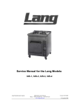
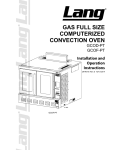
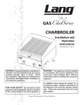
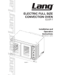
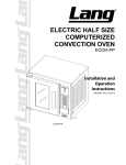
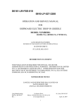
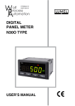
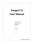
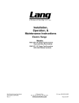
1
Installation, Operation, Maintenance and Service Instructions Micro Bakery Proofer and Staging Cabinet Model: MBPF 120, MBPF 220, MBPF 380 and MBSC Lang Manufacturing Part Number: 2M-W743 Rev. C 10 Sunnen Drive Ph: 314-678-6315 Fax: 314-781-2714 WWW.LANGWORLD.COM St. Louis, MO.63143-3800 September 08, 2015 THE INFORMATION IN THIS MANUAL IS CRUCIAL AND MUST BE RETAINED FOR FUTURE REFERENCE. READ, UNDERSTAND AND FOLLOW THE INSTRUCTIONS AND WARNINGS CONTAINED IN THIS MANUAL. DANGER POTENTIALLY HAZARDOUS SITUATION, WHICH, IF NOT AVOIDED, COULD RESULT IN DEATH. WARNING POTENTIALLY HAZARDOUS SITUATION, WHICH, IF NOT AVOIDED, COULD RESULT IN DEATH OR SERIOUS INJURY. CAUTION POTENTIALLY HAZARDOUS SITUATION WHICH, IF NOT AVOIDED, MAY RESULT IN MINOR OR MODERATE INJURY. NOTICE Helpful operation and installation instructions and tips are present. FOR YOUR SAFETY DO NOT STORE OR USE GASOLINE OR OTHER FLAMMABLE VAPORS AND LIQUIDS IN THE VICINITY OF THIS OR ANY OTHER APPLIANCE. WARNING: IMPROPER INSTALLATION, ADJUSTMENT, ALTERATION, SERVICE OR MAINTENANCE CAN CAUSE PROPERTY DAMAGE, INJURY OR DEATH. READ THE INSTALLATION, OPERATING AND MAINTENANCE INSTRUCTIONS THOROUGHLY BEFORE INSTALLING OR SERVICING THIS EQUIPMENT. Model #: Purchased From: Serial #: Location: Date Purchased: Date Installed: Purchase Order #: For Service, Call: Lang Manufacturing Part Number: 2M-W743 Rev. C 10 Sunnen Drive Ph: 314-678-6315 Fax: 314-781-2714 WWW.LANGWORLD.COM St. Louis, MO.63143-3800 September 08, 2015 TABLE OF CONTENTS CHAPTER PAGE Table Of Contents ................................................................ 3 Read First ............................................................................ 4 Safety Procedures ............................................................... 6 Equipment Description ......................................................... 7 Unpacking ............................................................................ 7 Installation ............................................................................ 8 Initial Start Up ...................................................................... 10 Cinnabon Operation Procedures ......................................... 11 Operation ............................................................................. 12 Maintenance & Cleaning ...................................................... 14 Troubleshooting ................................................................... 15 Parts List .............................................................................. 16 Exploded Views ................................................................... 17 Wiring Diagram .................................................................... 20 ETL File# 3029573 3 CAUTION CAUTION CAUTION THE UNIT IS EXTREMELY HEAVY. FOR SAFE HANDLING, INSTALLER SHOULD OBTAIN HELP AS NEEDED, OR EMPLOY APPROPRIATE MATERIALS HANDLING EQUIPMENT (SUCH AS A FORKLIFT, DOLLY, OR PALLET JACK) TO REMOVE THE UNIT FROM THE SKID AND MOVE IT TO THE PLACE OF INSTALLATION. ANY STAND, COUNTER OR OTHER DEVICE ON WHICH THE UNIT WILL BE LOCATED MUST BE DESIGNED TO SUPPORT THE WEIGHT OF THE UNIT. SHIPPING STRAPS ARE UNDER TENSION AND CAN SNAP BACK WHEN CUT. DANGER THIS APPLIANCE MUST BE GROUNDED AT THE TERMINAL PROVIDED. FAILURE TO GROUND THE APPLIANCE COULD RESULT IN ELECTROCUTION AND DEATH. WARNING INSTALLATION OF THE UNIT MUST BE DONE BY PERSONNEL QUALIFIED TO WORK WITH ELECTRICITY AND PLUMBING. IMPROPER INSTALLATION CAN CAUSE INJURY TO PERSONNEL AND/OR DAMAGE TO EQUIPMENT. UNIT MUST BE INSTALLED IN ACCORDANCE WITH ALL APPLICABLE CODES. NOTICE The data plate is located on the left-hand side of the unit towards the front. The unit voltage, wattage, serial number, wire size, and clearance specifications are on the data plate. This information should be carefully read and understood before proceeding with the installation. NOTICE The installation of any components such as a vent hood, grease extractors, fire extinguisher systems, must conform to their applicable National, State and locally recognized installation standards. NOTICE During the first few hours of operation, you may notice a small amount of smoke coming from the unit, and a faint odor from the smoke. This is normal for a new unit and will disappear after the first few hours of use. ALWAYS KEEP THE AREA NEAR THE APPLIANCE FREE FROM COMBUSTIBLE MATERIALS. CAUTION CAUTION WARNING CAUTION KEEP FLOOR IN FRONT OF EQUIPMENT CLEAN AND DRY. IF SPILLS OCCUR, CLEAN IMMEDIATELY, TO AVOID THE DANGER OF SLIPS OR FALLS. KEEP WATER AND SOLUTIONS OUT OF CONTROLS. NEVER SPRAY OR HOSE CONTROL CONSOLE, ELECTRICAL CONNECTIONS, ETC. MOST CLEANERS ARE HARMFUL TO THE SKIN, EYES, MUCOUS MEMBRANES AND CLOTHING. PRECAUTIONS SHOULD BE TAKEN TO WEAR RUBBER GLOVES, GOGGLES OR FACE SHIELD AND PROTECTIVE CLOTHING. CAREFULLY READ THE WARNING AND FOLLOW THE DIRECTIONS ON THE LABEL OF THE CLEANER TO BE USED. ETL File# 3029573 4 NOTICE WARNING CAUTION Service on this or any other, LANG appliance must be performed by qualified personnel only. Consult your authorized service agent directory or call the factory at 314-678-6315 or visit our website www.langworld.com or the service agent nearest you BOTH HIGH AND LOW VOLTAGES ARE PRESENT INSIDE THIS APPLIANCE WHEN THE UNIT IS PLUGGED/WIRED INTO A LIVE RECEPTACLE. BEFORE REPLACING ANY PARTS, DISCONNECT THE UNIT FROM THE ELECTRIC POWER SUPPLY. USE OF ANY REPLACEMENT PARTS OTHER THAN THOSE SUPPLIED BY LANG OR THEIR AUTHORIZED DISTRIBUTORS CAN CAUSE BODILY INJURY TO THE OPERATOR AND DAMAGE TO THE EQUIPMENT AND WILL VOID ALL WARRANTIES. ETL File# 3029573 5 SAFETY PROCEEDURES Lockout Procedure 1. Announce lockout to other personnel. 2. Turn both heat and control power off at main panel. 3. Test lockout by turning power switch on and observing if fan(s) come on. Check heater circuit with voltmeter. 4. Perform necessary repairs or tests. 5. Turn power on at main panel. 6. Announce unit is “on” to other personnel. Safety Precautions The manufacturer, Lang Manufacturing, hereby disclaims any and all responsibility for injury, damage, loss or other claim that may occur to person or property form improper alteration, modification, addition, operation, maintenance or service, whether it be mechanical, electrical, fuel, operator motor or otherwise, which may occur from such improper alteration, modification, addition, operation, maintenance or service to this piece of equipment. Safety Considerations Your Lang Proofing Cabinet is manufactured to rigid standards. This equipment is N.S.F., E.T.L and C.E. listed and meets safety and sanitation standards. The presence of safety equipment control and interlocks on an appliance and attendant components of installation cannot in and of themselves, assure absolute safety of operation. Diligent, capable, well-trained operators and maintenance personnel, as well as proper programs of operation and maintenance, are essential to the safe and reliable operation of this appliance. A. The responsibility of the manufacturer is to supply suitable, comprehensive instructions and recommendations for the operation and maintenance of the appliance. B. Trained qualified and factory-authorized personnel must perform all operation, maintenance and repair of these appliances. It is the responsibility of the owner / operator to ensure that this happens. C. A regular periodic program of cleaning, inspection and maintenance must be established and comprehensive maintenance records maintained. It is the sole responsibility of the user to establish, schedule and enforce the frequency and scope of these programs in keeping with recommended practice and with due consideration given to actual operating conditions. D. The appliance must be operated within the limits, which will not exceed the working limits of any component within the appliance as a whole. ETL File# 3029573 6 Equipment Description Model: MBPF Proofer, Micro Bakery Exterior The unit dimensions are 27⅞” (70.8cm) High with out legs, 46½” (118.10cm) Deep, and 30⅛” (76.5cm) Wide. The Sides, Bottom, and Rear wall are constructed stainless steel. The unit door is designed with a single pane window. Interior The interior dimensions are 18¾” (47.625cm) Wide, 26” (66cm) Deep, and 26⅜” (67cm) High. Controls The unit power switch applies power to the temperature and humidity controls. The unit has both humidity (water) and air (heat) elements. Both elements are easily accessible through the removable side panel. An infinite switch that has a range from low to high controls the humidity element. A thermostat that has a 140F (60° C) -temperature range controls the heating element. Unpacking Receiving the Unit Upon receipt, check for freight damage, both visible and concealed. Visible damage should be noted on the freight bill at the time of delivery and signed by the carrier's agent. Concealed loss or damage means loss or damage, which does not become apparent until the merchandise has been unpacked. If concealed loss or damage is discovered upon unpacking, make a written request for inspection by the carrier's agent within 15 days of delivery. All packing material should be kept for inspection. Do not return damaged merchandise to Lang Manufacturing Company. File your claim with the carrier. Location Prior to un-crating, move the unit as near its intended location as practical. The crating will help protect the unit from the physical damage normally associated with moving it through hallways and doorways. Un-crating The PFMB will arrive completely assembled inside a wood frame covered by cardboard box and strapped to a skid. Remove the cardboard cover, cut the straps and remove the wood frame. ETL File# 3029573 7 Installation CAUTION CAUTION CAUTION THE UNIT IS EXTREMELY HEAVY. FOR SAFE HANDLING, INSTALLER SHOULD OBTAIN HELP AS NEEDED, OR EMPLOY APPROPRIATE MATERIALS HANDLING EQUIPMENT (SUCH AS A FORKLIFT, DOLLY, OR PALLET JACK) TO REMOVE THE UNIT FROM THE SKID AND MOVE IT TO THE PLACE OF INSTALLATION. ANY STAND, COUNTER OR OTHER DEVICE ON WHICH THE UNIT WILL BE LOCATED MUST BE DESIGNED TO SUPPORT THE WEIGHT OF THE UNIT. SHIPPING STRAPS ARE UNDER TENSION AND CAN SNAP BACK WHEN CUT. INSTALLING THE CASTERS The PFMB comes standard with two swivel 4”and two rigid 4” casters that can be mounted on the bottom of the unit. Gently tip the unit onto its back. Bolt the swivel casters to the bottom front of the unit and the rigid casters to the bottom rear of the unit. See illustration below for reference. ETL File# 3029573 8 Installation cont’d DANGER THIS APPLIANCE MUST BE GROUNDED AT THE TERMINAL PROVIDED. FAILURE TO GROUND THE APPLIANCE COULD RESULT IN ELECTROCUTION AND DEATH. WARNING INSTALLATION OF THE UNIT MUST BE DONE BY PERSONNEL QUALIFIED TO WORK WITH ELECTRICITY AND PLUMBING. IMPROPER INSTALLATION CAN CAUSE INJURY TO PERSONNEL AND/OR DAMAGE TO EQUIPMENT. UNIT MUST BE INSTALLED IN ACCORDANCE WITH ALL APPLICABLE CODES. NOTICE The data plate is located on the left-hand side of the unit towards the front. The unit voltage, wattage, serial number, wire size, and clearance specifications are on the data plate. This information should be carefully read and understood before proceeding with the installation. NOTICE The installation of any components such as a vent hood, grease extractors, fire extinguisher systems, must conform to their applicable National, State and locally recognized installation standards. ELECTRICAL CONNECTION Electrical service can be provided through a 5/8” knock out, which is located at the back of the unit. A terminal block is provided inside the unit for hook up and can be accessed through the removable side panel. STACKING The MBPF (Micro Bakery Proofing Cabinet) and MBSC (Micro Bakery Staging Cabinet) are both part of a modular baking system and are both stackable. To stack the MBSC on the top of the MBPF, tip the MBSC onto its top and insert the four 3/8”-16 studs (pn: 2C-20108-11) into the AVK’s provided on the underside of the MBSC. Stack the MBSC onto the top of the MBPF and align the socket head screws with the holes provided in the top of the MBPF. To stack the EHS (oven) onto the MBSC, remove all racks and rack-slides from the inside of the oven and gently tip it onto its back. Insert the four 3/8”-16 studs (pn: 2C-20108-11) into the leg holes provided on the underside of the ECOH. Stack the ECOH onto the top of the MBSC and align the socket head screws with the holes provided in the top of the HCMB. VENTILATION AND CLEARANCES Standard minimum clearance from combustible construction is as follows: 0” from side 0” from back 0” from floor These units may be set directly, without legs, on a curbed base or noncombustible floor. ETL File# 3029573 9 Initial Start Up NOTICE During the first few hours of operation, you may notice a small amount of smoke coming from the unit, and a faint odor from the smoke. This is normal for a new unit and will disappear after the first few hours of use. Each unit is preheated, tested and calibrated at the factory before shipment. However, due to temperature and climate changes during shipment the unit can absorb moisture and should be dried out before attempting to proof. Prior to putting any unit into full time operation at normal cooking temperatures, it must be thoroughly "seasoned" or dried out. Moisture absorption in the closed spaces and even inside the heating elements can cause future trouble if not properly treated. Before the initial use of the unit, the element must be thoroughly allowed to dry out. This can be done by setting the thermostat to the maximum setting and humidity control to the lowest setting. Allow the unit to saturate until all vapor and condensation has been eliminated. For best operating results allow the unit to thoroughly dry out for 8 to 12 hours. If the unit is out of use for three or more days, a one-hour preheat schedule should be used, especially when exposed to high humidity and/or cool temperatures. ETL File# 3029573 10 Cinnabon Operations Cinnabon Micro Bakeries Instructions Proofing: Proofer should be filled with HOT water first thing each morning. Controls should be set at Medium-to-Medium Low----- Temperature 110 degrees. Check water level midway through each day. Drain water completely at end of day. Cold Proofer: Time clips will be placed under each pan (not inside the pan) in cold proofer to allow expiration time to be easily read. Cold proofer will hold a maximum of eight pans. Baking---Oven: The new Micro Lang Oven is equipped with four shelves. When baking place one pan on each rack to ensure even baking. When volume levels require additional baking you may bake two pans on every other shelf. Baking more will result in uneven bakes. The control panel is identical to the full size oven and should be used in the same manner. ETL File# 3029573 11 OPERATION CAUTION ALWAYS KEEP THE AREA NEAR THE APPLIANCE FREE FROM COMBUSTIBLE MATERIALS. CAUTION KEEP FLOOR IN FRONT OF EQUIPMENT CLEAN AND DRY. IF SPILLS OCCUR, CLEAN IMMEDIATELY, TO AVOID THE DANGER OF SLIPS OR FALLS. GENERAL The unit is designed to give well regulated, even heat. It should be thoroughly preheated before being used. It is advantageous from the operating cost standpoint, to operate with the thermostat set at the lowest possible position that will satisfactory perform the proofing and with the door shut during preheat and slack business periods. STARTUP 1. Open the drop down door below the control panel and fill the water tray with WARM water. 2. Set the Power Switch to the “ON” position. 3. Set the Temperature Dial to the desired temperature. 4. Set the Humidity Dial to the Medium position (adjust as necessary to gain the desired humidity). 5. Allow the proofer to preheat for 1 hour. 6. Load product. 7. Shut door and keep closed. 8. Refill water pan as required during the day. Proofing General Proofing is one of the most important and delicate stages in baking. About 50% of the product volume is created in the proofer. Proofing accelerates the fermentation of yeast in a warm moist environment causing the dough to rise. The temperature of the proofer should not be set higher then 100F. The humidity should be set at around medium. For optimum results, rolls should be removed from the hot proofer and transferred to the cold proofer at minimum proof. This will ensure that they can be held for 40 minutes without becoming over-proofed. ETL File# 3029573 12 Operation PROOFING SPECIFICS There are many variables involved in the baking process. It is difficult to assign proofing times, temperatures, and humidity levels. Here are some general guidelines that may be helpful. Temperature, age, and volume of dough should be the same to obtain similar results (keep accurate records). Never proof frozen dough before thawing. Thaw in a retarder set between 38F and 42F for 12-16 hours. (A retarder is simply a high humidity level refrigerator). If dough had been retarded or refrigerated, allow some “Floor” time. (“Floor” time is simply allowing the product to sit at room temperature). Thirty minutes is usually sufficient. This allows the dough temperature to rise throughout gradually. Set humidity control just high enough so an undesirable crust is not formed during the proofing process. Different products are proofed at different temperatures ranging between 80F and 105F. The lower temperatures are used for croissants or butter layered pastries. Butter melts at 87F. The higher proofing temperatures are used for products such as breads and rolls. Never exceed 105F; temperatures over 107F will kill the fermentation process of the yeast. A product has fully proofed when it doubles in size, appears loose, and feels light and fluffy. A product is under proofed if it has not doubled in size. An under proofed product does not have an appealing appearance and will not expand to its full size during baking. A product is over proofed because of too much time in the proofing stage. It will spread too much in the pan and fall when handled or baked. ETL File# 3029573 13 Maintenance & Cleaning WARNING KEEP WATER AND SOLUTIONS OUT OF CONTROLS. NEVER SPRAY OR HOSE CONTROL CONSOLE, ELECTRICAL CONNECTIONS, ETC. CAUTION MOST CLEANERS ARE HARMFUL TO THE SKIN, EYES, MUCOUS MEMBRANES AND CLOTHING. PRECAUTIONS SHOULD BE TAKEN TO WEAR RUBBER GLOVES, GOGGLES OR FACE SHIELD AND PROTECTIVE CLOTHING. CAREFULLY READ THE WARNING AND FOLLOW THE DIRECTIONS ON THE LABEL OF THE CLEANER TO BE USED. DAILY CLEANING The unit should be thoroughly cleaned once a day to insure against accumulation of foreign material. Always start with a cold unit. Always follow the cleaner manufacturer's instructions when using any cleaner. Care should be taken to prevent caustic cleaning compounds from coming in contact with the aluminized inside of the unit. The unit rack, rack slides and interior can be cleaned using warm water and mild detergent. Always apply these cleaners when the unit is cold and rub in the direction of the metal's grain. WEEKLY CLEANING To provide the proper atmosphere for proofing or holding, Lang has designed a sealed cabinet. A characteristic of the unit is an accumulation of water on the bottom of the cabinet. This accumulation should be removed daily. This is easily accomplished by simply removing the rack and rack slides from the unit and sponging out any excess accumulation of water. It may also be necessary to clean the water reservoir once a week to remove any mineral deposits that may have built up after heavy use. Remove the racks and right hand rack slide from the unit. Remove the four wing nut screws on the right hand side of the unit. This will expose the water reservoir. Use a sponge and some mild soap and water to remove any mineral deposits. ETL File# 3029573 14 Troubleshooting Symptoms What follows is a chart of Symptoms, Possible Causes, and Remedy’s to aid in diagnosing faults with the unit. Refer to the Symptoms column to locate the type of failure then to the Possible Cause for the items to be checked. On the following pages is a chart with the possible causes and the test to properly identify the problem. SYMPTOM POSSIBLE CAUSE Unit will not heat No power to Unit Defective power switch Defective thermostat Defective heat element Unit will not proof No power to unit Defective power switch Defective infinite switch Defective water element NOTICE Service on this or any other, LANG appliance must be performed by qualified personnel only. Consult your authorized service agent directory or call the factory at 314-678-6315 or visit our website www.langworld.com for the service agent nearest you. WARNING CAUTION BOTH HIGH AND LOW VOLTAGES ARE PRESENT INSIDE THIS APPLIANCE WHEN THE UNIT IS PLUGGED/WIRED INTO A LIVE RECEPTACLE. BEFORE REPLACING ANY PARTS, DISCONNECT THE UNIT FROM THE ELECTRIC POWER SUPPLY. USE OF ANY REPLACEMENT PARTS OTHER THAN THOSE SUPPLIED BY STAR OR THEIR AUTHORIZED DISTRIBUTORS CAN CAUSE BODILY INJURY TO THE OPERATOR AND DAMAGE TO THE EQUIPMENT AND WILL VOID ALL WARRANTIES. TESTS Possible Cause TEST Defective Power Switch Check power switch for normal operation Failed thermostat Check thermostat for correct voltage* Verify calibration Replace if necessary* Failed element Check elements for correct voltage* Remove the wires and check for continuity across the element* Failed infinite switch Check switch for correct voltage. * A factory authorized service representative should perform this work. ETL File# 3029573 15 1 2 32 31 33 25 5 6 7 8 9 See Detail B SEE DETAIL A 3 10 17 22 16 21 29 28 27 26 20 18 12 19 13 11 4 14 30 15 25 23 24 ® Model: MBPF Electric Proofer PFMB Electric Proofer SK2269 1 Rev. A 6/03/08 PARTS LISTSeptember 08, 2015, Rev. C MBPF Electric Proofer Key Number Part Number 1 2 3 4 5 6 7 8 9 10 11 12 13 14 15 16 17 18 19 20 21 22 23 24 25 26 27 28 29 30 31 32 33 Q9-162-106 Q9-162-104 Q9-162-102 Q9-162-118 2T-30401-28 2C-20103-06 2C-20103-02 2E-31200-02 2C-20103-07 2E-30500-01 2P-72900-04 2P-72901-17 2A-72500-05 2C-20201-07 2C-20202-05 2C-20104-10 2K-70101-101 2V-70400-05 2C-20204-01 2C-20301-11 Q9-162-116 2N-11162-04 2N-11162-08 2N-11162-10 2N-11162-11 Q9-162-102 2C-20112-03 2B-50200-96 Q9-162-101 Q9-162-711 SEE DETAIL A 2C-20103-02 Q9-162-715 Q9-162-103 2K-70801-15 2E-31107-02 Q9-31107-02-W1 2P-51001-37 2U-30200-28 2U-30200-43 Q9-162-170 Q9-162-720 Y9-70602-01-1 NI NI NI NI NI NI Number Per Unit Description 1 1 1 1 1 2 1 1 2 1 2 2 4 3 4 13 1 1 2 2 1 1 1 1 1 1 4 1 1 1 1 4 1 1 1 1 1 BODY TOP BODY REAR BODY RIGHT SIDE ACCESS COVER STAT FXD TEMP OPEN 160 SCRW SM PLT 6 X3/8 PHL SCRW SM PLT 10 X .5 PHLSL TP A LUG GROUNDING UL APPROVED SCRW PHD SM 8 X PHL TYP A TRM STRP 2 POLE 30A 300V CSTER RIGID 3,5/16W TRD. CSTR SWVL W/BRK 35/16TRD LEG 4 W/BOLT DOWN ADJ WSHR FLT 1/4 SAE PLTD WSHR PLT 1/4 LOCK SPLIT SCRW HXHD CAP 5/16 -18X 3/4 HOSE BARB 45 DEG ELBOW TO VALVE 1/4 MINI BALL WSHR LOCK SS #10 STD SPLIT NUT HEX 8-32 PLTD WATER ELEMENT MOUNT ELEMENT H2O PROOFER 120V ELEMENT H2O PROOFER 240V ELEMENT AIR, PFMB 120V ELEMENT AIR, PFMB 220V AIR DUCT COVER SCRW THUMB 1/4-20 X 1/2 SS RACK SLIDE-PFMB STAINLESS BODY FRONT WATER DOOR ASSY PFMB COMPONENT ASY PFMB 120V SCRW SM PLT 10 X .5 PHLSL TP A PROOFER DOOR ASSY PFMB BODY LEFT SIDE STRAIN RELIEF BUSH STRT CORD SET 14/3 X 8’ 15A CORDSET 250V 14/3 15A ALL ALL ALL ALL ALL ALL MBPF-220V(QTY=5), MBPF-2/3VCN(QTY=5) ALL ALL ALL ALL ALL MBPF-120VM MBPF-120VM (QTY=6) MBPF-120VM (QTY=7) ALL ALL ALL ALL ALL ALL MBPF-120V & CN & M MBPF-2/3VCN, 220V & CN MBPF-120V & CN & M MBPF-2/3VCN, 220V & CN ALL ALL ALL ALL ALL ALL ALL ALL ALL ALL MBPF-120V & CN & M MBPF-208/240V 1 1 1 4 1 1 SPRING SWT DR HINGE S/S MOTOR PROOFER 120V W/FAN MOTOR PROOFER 240V W/FAN MARINE LEG ADAPTER MARINE LEG ASSEMBLY CATCH 1/4 BULLET W/CLIP ALL MBPF-120V & CN & M MBPF-2/3VCN, 220V & CN MBPF-120VM MBPF-120VM ALL 2 1 2 3 4 12 11 10 5 9 13 6 8 DETAIL A DETAIL 7 B 14 15 16 17 18 19 ® Model: MBPF Detail A & B PFMB Detail A & B SK2271 3 Rev. A 6/03/08 PARTS LISTSeptember 08, 2015, Rev. C MBPF Electric Proofer Controls Assembly Key Number 1 2 3 4 5 6 7 8 9 10 11 12 13 14 15 16 17 18 19 Part Number Number Per Unit 2E-30303-19 1 2T-30402-39 1 2E-30305-04 1 2E-30305-01 1 2J-30801-01 1 Q9-162-117-01 1 2M-60301-157 1 2M-60301-144 1 2R-70701-46 1 2R-70701-45 1 2R-70701-44 1 2C-20101-77 2J-31601-19 1 2J-31601-17 1 2J-31601-18 1 2J-31601-16 1 2C-20301-29 3 2P-72901-17 2 2P-72901-04 2 2C-20202-08 13 2C-20201-07 3 2C-20202-05 3 2C-20104-10 13 2C-20104-08 3 Description SWT TOG ON-ON DPDT BLK STAT ADJ 0-140 F 60 CAP SWTINF120V15AMPINF120-252 SWT INF 240V 15AMP TIMER MECHANICAL LONG CONTROL PANEL W / TIMER LABEL PANEL PRFR M.B. LABEL PANEL CINNABON BK KNB WH RNG&ARR 3-16SH BK KNB BLUE RNG&ARR 1/4SH BK KNOB RED RNG & ARR 1/4 SCRW MS PLT 6-32 X 0.25 PILOT LT 125V 6LEAD WHITE PILOT LT 250V 6LEAD WHITE PILOT LT 125V 6LEAD GREEN PILOT LT 250V 6LEAD GREEN NUT HEX ACORN 1/4-20 S/S CSTR SWVL W/BRK 35/16TRD CSTER RIGID 3,5/16W TRD. WSHR PLT 5/16 LOCK SPLIT WSHR FLT 1/4 SAE PLTD WSHR PLT 1/4 LOCK SPLIT SCRW HXHD CAP 5/16-18X3/4` SCRW HXHD CAP PLT 1/4-20 4 ALL ALL MBPF-120V & CN & M MBPF-2/3VCN, 220V & CN MBPF-120V & M, 220V ALL MBPF-120V & M, 220V MBPF-120VCN, 2/3VCN & 220VCN MBPF-120V & M, 220V ALL ALL ALL MBPF-120V & CN & M MBPF-2/3VCN, 220V & CN MBPF-120V & CN & M MBPF-2/3VCN, 220V & CN ALL ALL ALL ALL ALL ALL ALL ALL 1 8 7 6 5 2 3 4 Model: MBSC Proofer Holding Cabinet HCMB Proofer Holding Cabinet SK2271 5 Rev. - 7/10/07 PARTS LISTSeptember 08, 2015, Rev. C MBSC, HCMB PROOFER HOLDING CABINET Key Number 1 2 3 4 5 6 7 8 Part Number Q9-163-701 Q9-163-701-1 Q9-163-121 Q9-163-121-1 Q9-163-704 Q9-163-704-1 Q9-163-125 2C-20301-07 2C-20301-20 2C-20111-01 Q9-163-122 Q9-163-122-1 Number Per Unit 1 1 1 1 1 1 1 2 2 2 1 1 Description BODY ASSEMBLY 11 3/8 TALL BODY ASSEMBLY 13 3/8 TALL DOOR CATCH RH ARM 11 3/8 DOOR CATCH RH ARM 13 3/8 DOOR ASSEMBLY 11 3/8 TALL DOOR ASSEMBLY 13 3/8 TALL SHELF NUT ACORN 1/4-20 PLTD NUT LOCK STOVER 1/4-20 PLTD SCRW HXHD CAP 1/4-20X1/2 SS` DOOR CATCH LH ARM 11 3/8 DOOR CATCH LH ARM 13 3/8 6 MBSC MBSCT MBSC MBSCT MBSC MBSCT BOTH BOTH BOTH BOTH MBSC MBSCT Wiring Diagram TB 1 TB - TERMINAL BLOCK TS - TOGGLE SW ITCH PL - PILOT LIGHT TMST - THERMOSTAT IC - INFINITE CONTROL HE - HEATING ELEMENT FM - FAN MOTOR OTS - OVERTEMP STAT 2 TS TS 4A 3 OTS 5A 4 5 PL (POW ER) 4 5 FM to 5 7 TMST 4 HE (AIR) 6 4 PL (HEAT) 5 4 IC IC 9 8 HE (W ATER) ETL File# 3029573 21 Limited Warranty Commercial Cooking Equipment (Within the contiguous U.S., including Alaska and Hawaii, and Canada) Lang Manufacturing Equipment (“Lang Equipment”) has been skillfully manufactured, carefully inspected and packaged to meet rigid standards of excellence. Lang Manufacturing Company warrants products produced and sold by Lang Manufacturing Company and its duly authorized agents, against defects in materials and workmanship within the following limitations: • • • What is Provided: Limited replacement parts as specified below, including standard ground shipping from Lang or service parts center when required. Limited labor for repair as specified below, including authorized service agent’s transportation, portal to portal, up to one hundred (100) miles round trip and two (2) hours travel time. Lang, or an authorized service representative, will repair or replace, at Lang’s sole discretion, any Lang equipment, including but not limited to the listed exclusions. Coverage Period: Extending from the date of shipment from Lang manufacturing or its duly authorized dealer/distributor for the specified period. • • • • • PB12, PB24, PBE12, PBE24 PaneBella toasters for a period of 24 months from installation or 30 months from shipment from Lang (which ever comes first) limited to parts and labor. All removable parts and components including but not limited to: Burners, Racks, Valves, Grates, Grease Trays, Quartz Heaters for a period of three (3) months limited parts and labor, from date of shipment. All other Lang products and applications for a period of 12 months from installation or 18 months from the date of shipment from Lang (which ever comes first) limited parts and labor. Limited Life-time warranty on unison doors for ECOF, GCOF, ECSF and GCSF convection ovens. After a period of three (3) years from the date of shipment from Lang, the warranty will exclude labor, travel, mileage or any other incidental charges associated with the replacement of the oven door(s). Replacement parts shall be warranted for a period of ninety (90) days after installation by an authorized Lang service agent. Conditions: • • Covered equipment must be properly installed and according to the requirements of the installation manual and all applicable local codes. Equipment used under conditions of abuse, misuse, carelessness or abnormal conditions including equipment subjected to harsh or inappropriate chemicals, poor water quality or equipment with missing or altered serial numbers. • The Lang Equipment Warranty Policy states that any water connected to a Lang appliance must be in compliance with the following WATER TREATMENT REQUIREMENTS o Cold water, 30 to 80 PSI o Maximum Salinity and Ion content: o pH between 6.8 and 7.6 Chlorine: < 0.5 ppm o Conductivity less than 1/500,000 Ω per Chlorides: < 30 ppm inch Sulfates: < 40 ppm o Total dissolved solids less than 100 ppm Iron: < 0.1 ppm o Hardness from 5.3 to 7.3 grains per Copper: < 0.05 ppm gallon Manganese: < 0.05 ppm Chloramines: < 0.5 ppm It is the responsibility of the purchaser to install and maintain the water supply to the appliance. Failure to provide satisfactory water quality of the appliance in accordance with the operating manual requirements can cause damage to internal components and will VOID the warranty. Star Manufacturing International, 10 Sunnen Drive, St. Louis, MO 63143 314-678-6315 STAR INTERNATIONAL HOLDINGS INC. COMPANY Star - Holman - Lang - Wells - Bloomfield - Toastmaster 10 Sunnen Drive, St. Louis, MO 63143 U.S.A. (314) 678-6303 www.star-mfg.com