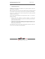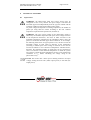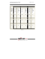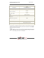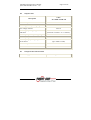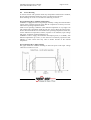
1
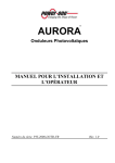
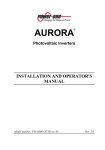
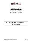
®
AURORA
Photovoltaic Inverters
INSTALLATION AND OPERATOR’S
MANUAL
Model number: PVI-2000-OUTD-UK
Rev. 1.0
Installation and Operator’s Manual
(PVI-2000-OUTD-UK Rev: 1.0)
Page 2 of 62
REVISION TABLE
Document
Revision
Author
Date
0
M. Trova
Dec. 17, 2006
Change Description
First release of the document
SAVE THESE INSTRUCTIONS !
IMPORTANT SAFETY INSTRUCTIONS
POWER-ONE: Reproduction and disclosure, even partially, of the contents of
this manual are strictly forbidden without prior authorization of
Power-One.
Installation and Operator’s Manual
(PVI-2000-OUTD-UK Rev: 1.0)
Page 3 of 62
IMPORTANT SAFETY INSTRUCTIONS
This manual contains important safety and operational instructions that must be
accurately understood and followed during the installation and maintenance of the
equipment.
To reduce the risk of electrical shock hazards, and to make sure the equipment is
safely installed and commissioned, special safety symbols are used in this manual
to highlight potential safety risks and important safety information. The symbols
are:
WARNING: the paragraphs highlighted by this symbol contain
processes and instructions that must be absolutely understood and
followed to avoid potential danger to people.
NOTE: the paragraphs highlighted by this symbol contain processes and
instructions that must be rigorously understood and followed to avoid
potential damage to the equipment and negative results.
The equipment is provided with several labels, some of them with a yellow
background, which are related to safety issues.
Make sure to read the labels and fully understand them before installing the
equipment.
The labels utilize the following symbols:
Equipment grounding conductor (Main grounding protective earth,
PE)
Alternate Current (Ac) value
Direct Current (Dc) value
Phase
Grounding (Earth)
Installation and Operator’s Manual
(PVI-2000-OUTD-UK Rev: 1.0)
Page 4 of 62
USEFUL INFORMATION AND SAFETY STANDARD
FOREWORD
¾ The installation of AURORA must be performed in full compliance with
national and local standards and regulations
¾ AURORA has no internal user serviceable parts.
For any maintenance or repair please contact the nearest authorized repair
center. Please contact your reseller if you need to know the nearest authorized
repair center.
¾ Read and understand all the instructions contained in this manual and become
familiar with the safety symbols in the relevant paragraphs before you install
and commission the equipment
¾ The connection to the distribution grid must be done only after receiving
approval from the distribution utility as required by national and state
interconnection regulations, and can be done only by qualified personnel.
¾ Cover the photovoltaic panels with dark opaque sheets before they are
connected to avoid (prevent) any chance (possibility) of high voltages
appearing at the connecting cable terminations.
GENERAL
During inverter operation, some parts can be powered, some not properly insulated
and, in some cases, some parts can move or rotate, or some surfaces can be hot.
Unauthorized removal of the necessary protections, improper use, incorrect
installation or incorrect operation may lead to serious damage to people and
objects.
All transport, installation and start-up, as well as maintenance operations, shall be
carried out by skilled and trained personnel (all national regulations on accidents
prevention shall be complied with ! ! !).
According to these basic safety rules, qualified and trained people have skills for
the assembling, start-up and operation of the product, as well as the necessary
requirements and qualifications to perform such operations.
ASSEMBLY
Devices shall be assembled and cooled according to the specifications mentioned
in the corresponding documents.
In particular, during transport and handling, parts shall not be bent and/or the
insulation distances shall not be changed. There should be no contact between
electronic parts and connection terminals.
Installation and Operator’s Manual
(PVI-2000-OUTD-UK Rev: 1.0)
Page 5 of 62
Electrical parts must not be mechanically damaged or destroyed (potential health
risk).
ELECTRICAL CONNECTION
With the inverter powered, comply with all prevailing national regulations on
accidents prevention.
Electrical connections shall be carried out in accordance with the applicable
regulations, such as conductor sections, fuses, PE connection.
OPERATION
Systems equipped with inverters shall be provided with further control and
protective devices in compliance with the corresponding prevailing safety rules,
such as those relating to the compliance with technical equipment, accidentpreventing regulations, etc. Any calibration change shall be made using the
operational software. Once the inverter has been disconnected from the power grid,
powered parts and electrical connections shall not be touched as some capacitors
could be charged.
Comply with all corresponding marks and symbols present on each device. During
operation, make sure that all covers and doors are closed.
MAINTENANCE AND SERVICE
Comply with manufacturer’s recommendations.
SAVE ALL DOCUMENTS IN A SAFE PLACE !
Installation and Operator’s Manual
(PVI-2000-OUTD-UK Rev: 1.0)
Page 6 of 62
PVI-2000-OUTD-UK
This document applies to the above-mentioned inverters, only.
UK
Fig. 1 - Product label
The identification plate present on the inverter includes the following data:
1) Manufacturer Part Number (11 digits)
2) Model Number
3) Serial Number
4) Production Week/Year
Installation and Operator’s Manual
(PVI-2000-OUTD-UK Rev: 1.0)
Page 7 of 62
CONTENTS:
1 FOREWORD
1.1 PHOTOVOLTAIC ENERGY
2 SYSTEM DESCRIPTION
2.1 Main Elements of a PV System: “STRINGS and ARRAYS”
2.2 Data Transmission and Check
2.3 AURORA Technical Description
2.4 Protective Devices
2.4.1
Anti-Islanding
2.4.2
Panel Ground Fault
2.4.3
Further Protective Devices
3 INSTALLATION
3.1 Package Inspection
3.2 Package Check List
3.3 Choosing Installation Location
3.4 Wall Mounting
3.5 Preliminaries to Electrical Connections
3.6 Electrical connection
3.7 Acces to the terminal blocks by removing the right side panel
4 START-UP
5 MONITORING AND DATA TRANSMISSION
5.1 User’s Interface Mode
5.2 Available Data
5.2.1
Real time data
5.2.2
Internally Logged Data
5.3 LED Indicators
5.4 Messages and Error Codes
5.5 LCD Display
6 DATA CHECK AND COMMUNICATION
6.1 RS-485 serial link
6.2 Power Line Modem (PLM)
6.3 Display Menu
6.4 Address information
6.5 Manual address setting
6.6 Baud Rate setting
6.7 Measurement accuracy
7 TROUBLESHOOTING
8 TECHNICAL FEATURES
8.1 Input Values
9
9
10
10
12
13
14
14
14
15
15
15
16
17
18
21
24
26
27
28
28
30
30
30
31
36
38
44
44
47
49
50
50
51
53
54
56
56
Installation and Operator’s Manual
(PVI-2000-OUTD-UK Rev: 1.0)
8.2
8.3
8.4
8.5
Output Values
Grid protection characteristics
General characteristics
Power Derating
Page 8 of 62
59
59
60
61
Installation and Operator’s Manual
(PVI-2000-OUTD-UK Rev: 1.0)
1
Page 9 of 62
FOREWORD
This document contains a technical description of the AURORA photovoltaic
inverter so as to provide the installer and user all the necessary information about
installation, operation and use of AURORA.
1.1
PHOTOVOLTAIC ENERGY
Industrialized countries (greater energy consumers) have been experimenting with
energy-saving methods and reducing pollutant levels. This may be possible
through a shrewd and rational consumption of well-known resources, and also by
looking for new forms of clean and in exhaustible energy.
Renewable sources of energy are fundamental to solving this problem. Under these
circumstances, solar energy exploitation to generate electrical (photovoltaic)
energy is becoming more and more important worldwide.
Photovoltaic energy, in any case, is of great advantage to the environment because
the radiated energy we receive from the sun is transformed directly into electrical
energy without any combustion process and without producing any pollution.
Installation and Operator’s Manual
(PVI-2000-OUTD-UK Rev: 1.0)
2
Page 10 of 62
SYSTEM DESCRIPTION
AURORA is an inverter able to feed energy to the electrical power distribution
grid.
Photovoltaic panels transform the solar radiation into electrical energy in the form
of direct (Dc) current (through a photovoltaic field, also known as PV generator).
In order to utilize this energy and feed it back to the distribution grid, this energy
shall be turned into alternating (Ac) current. AURORA does this conversion, also
known as Dc to Ac inversion, in a very efficient way, without using rotating parts
but just static power electronic devices.
When used in parallel with the grid, the alternate current generated by the inverter
is directly fed to the domestic distribution circuit, which in turn is also connected
to the public power distribution grid.
The solar energy system can thus feed power to all the connected users, such as
lighting devices, household appliances, etc.
If the energy generated by the photovoltaic system is not enough, the energy
necessary to ensure the standard operation of the connected users is drawn from
the public power distribution grid. Any excess energy produced by the inverter is
exported to the grid.
According to national and local standards and regulations the produced energy can
be sold to the grid or credited to the user against future consumption.
2.1
Main Elements of a PV System: “STRINGS and ARRAYS”
The so-called “string” technology has been developed in order to reduce the
installation costs of a photovoltaic system as much as possible. These costs are
mainly related to the wiring operations on the Dc side of the inverter and the
consequent distribution on the Ac side.
A photovoltaic PANEL is composed of many photovoltaic cells assembled on the
same mount. A STRING is composed of a certain number of panels electrically
connected in series. An ARRAY is composed of one or more strings connected in
parallel.
Larger photovoltaic systems, can be composed of a certain number of arrays,
connected to one or more AURORA inverters. By maximizing the number of
panels in series per string, the cost and complexity of the system wiring can be
reduced.
Installation and Operator’s Manual
(PVI-2000-OUTD-UK Rev: 1.0)
Page 11 of 62
PV Cell
+
PV Panel
PV String
+
+
_
PV Array
_
_
Fig.2 Array Composition
Array voltage value shall be within an acceptable range for the inverter. Please
refer to the technical data for the AURORA for details on the Dc operating voltage
range (see Section 8.1 “Input Values” for more details).
WARNING: String voltage shall not exceed 600Vdc for any reason, so
as to avoid damage to the equipment.
NOTE: A minimum string voltage value of 200Vdc is required to startup the grid connection sequence of AURORA. Once connected,
AURORA will transfer to the grid the maximum power available from
the string for any DC input voltage value in the range from 90Vdc to
580Vdc.
Installation and Operator’s Manual
(PVI-2000-OUTD-UK Rev: 1.0)
Page 12 of 62
The total current of an array must also be within the capability limits of the
inverter. The 2000W model of AURORA is capable of handling a single array. For
AURORA the maximum input current shall not exceed 10Adc.
In case the photovoltaic system exceeds the capabilities of a single AURORA
inverter, additional inverters can be added to the system, each connected to a
suitable section of the photovoltaic field on the Dc side, and to the grid on the Ac
side. Each AURORA inverter will work independent of the others and will transfer
to the grid the maximum power available from its own section of the photovoltaic
panels.
The actual decisions on the way the photovoltaic system is structured and wired
depend on a number of factors and considerations, such as type and model of
panels, available area, location, energy targets, as well as on good design practices.
Power-One provides a system configuration tool on its website (www.power-one
.com) that can assist in modeling the system.
Outdoor
Fig.3 Simplified diagram of a photovoltaic system
2.2
Data Transmission and Check
In case multiple inverters are used, they can be monitored remotely by using an
advanced communication system based on the serial interface RS485 or on the
Power Line Modem (PLM) technology. For further information, refer to the
corresponding sections of this manual.
Installation and Operator’s Manual
(PVI-2000-OUTD-UK Rev: 1.0)
2.3
Page 13 of 62
AURORA Technical Description
Figure 4 shows a block diagram of AURORA. The main blocks are the input DcDc converter (called booster) and the output inverter. Both the Dc-Dc converter
and the output inverter work at high switching frequency to minimize size and
weight.
This model of AURORA is transformer-less, that means that there is no galvanic
isolation between input and output. This allows an increase to the inverter
efficiency. AURORA is equipped with all the protection needed to operate safely
and to comply with existing safety regulations even without an isolation
transformer.
Fig.4 AURORA block diagram
Thanks to its high efficiency and large heat-sink, AURORA offers max. power
operation over a wide ambient temperature range.
The inverter is digitally controlled by means of two independent Digital Signal
Processors (DSP), and one microprocessor.
Two single-chip independent computers maintain control in full compliance with
the electric standards relating to systems power supply and safety.
Installation and Operator’s Manual
(PVI-2000-OUTD-UK Rev: 1.0)
Page 14 of 62
The AURORA operating system performs inter-process communication checks to
ensure the entire unit operates properly.
This process ensures optimal performance levels of the whole unit, as well as a
high efficiency under all solar radiation and load conditions, always in full
compliance with the applicable directives, standards and regulations.
2.4
2.4.1
Protective Devices
Anti-Islanding
When the local power distribution grid is interrupted due to a fault or maintenance
purposes, or when the equipment is shut down for maintenance operations,
AURORA shall be physically disconnected under safety conditions, so as to
protect the people working on the grid, in full compliance with the applicable
prevailing national standards and regulations. To avoid any possible islanding
operation, AURORA is provided with an automatic disconnection protective
system called Anti-Islanding.
The AURORA PVI-2000-OUTD-UK model is equipped with an advanced AntiIslanding protection certified according to:
¾ UK G83\1
2.4.2
Panel Ground Fault
This version of Aurora is designed for connection to floating Photovoltaic array
only, with the positive and negative terminals from the panels are not connected to
the Ground (the metallic support of the panel instead shall be connected to safety
Ground in accordance with existing electrical safety regulations). An advanced
ground fault protection circuit continuously monitors the ground connection and
shuts down AURORA in case a ground fault is detected and indicates the ground
fault condition by means of a red LED on the front panel. AURORA is equipped
with a (chassis) ground screw clamp, which shall be used for connection of the
plant Protective Earth conductor (equipment grounding conductor). See section
3.5 for detailed grounding instructions.
WARNING: Do not connect the AURORA inverter to Bi-polar
configured arrays. The AURORA inverter is designed for connection to
floating Photovoltaic arrays only.
NOTE: For detailed information on AURORA disconnection and on
malfunctioning causes, refer to the corresponding sections.
Installation and Operator’s Manual
(PVI-2000-OUTD-UK Rev: 1.0)
2.4.3
Page 15 of 62
Further Protective Devices
AURORA is equipped with additional protections to guarantee safe operation
under all circumstances. The protections include:
¾
Continuous monitoring of the grid voltage to ensure the frequency and
voltage values are within the proper operational limits;
¾
Control of the internal temperatures to automatically drive the speed of the
external cooling fan. This will allow the inverter to deliver the maximum
output power for ambient temperatures up +40 ° C
The AURORA is designed for safe and reliable operation. This is made possible
by the use of redundant control circuits.
3
INSTALLATION
WARNING: The electrical installation of AURORA must be made in
accordance with the electrical standards prescribed by the local
regulations.
WARNING: The connection of AURORA to the electrical distribution
grid must be performed only after receiving authorization from the utility
that operates the grid.
3.1
Package Inspection
NOTE: The distributor presented your AURORA to the delivering carrier
securely packed and in perfect condition. Upon acceptance of the package
from the distributor the delivering carrier assumes responsibility for its
safe arrival to you. Regardless of the attention paid by carrier in handling
it, sometimes the package and its contents might be damaged.
Please, carry out the following checks:
¾ Examine the shipping box for any visible damage: punctures, dents or any
other signs of possible internal damage;
¾ Describe any damage or shortage on the receiving documents and have the
carrier sign their full name;
¾ Open the shipping box and inspect the contents for internal damage. While
unpacking, be careful not to discard any equipment, parts or manuals. If any
damage is detected, call the delivering carrier to determine the appropriate
Installation and Operator’s Manual
(PVI-2000-OUTD-UK Rev: 1.0)
¾
¾
¾
3.2
Page 16 of 62
action. They may require an inspection. Save all shipping material for the
inspector to see!
If the inspection reveals damage to the inverter call your supplier, or
authorized distributor. They will determine if the equipment should be
returned for repair. They will also provide instructions on how to get the
equipment repaired;
It is your responsibility to file a claim with the delivery carrier. Failure to
properly file a claim for shipping damages may void warranty service for any
physical damages later reported for repair;
Save AURORA original packaging, as it will have to be used in case the
equipment has to be shipped out for repairs, or the responsible inspector
requires it.
Package Check List
Description
Photovoltaic Inverter
Bag with 4 screws, 4 blocks and
1 Tap wrench Torx TX20.
Connector kit including: 1 cable
gland PG16,5 with 2 holes
gasket, mating connector for
(Binder) AC connection
One mounting reference
drawing
One copy of this manual
One certificate of warranty
CD-Rom with communication
software
Quantity
1
1
1
1
1
1
Installation and Operator’s Manual
(PVI-2000-OUTD-UK Rev: 1.0)
3.3
Page 17 of 62
Choosing Installation Location
The location for the installation of AURORA should be selected in accordance to
the following recommendations:
¾
AURORA should be placed at a suitable height from ground to allow easy
reading of the front display and the status LEDs.
¾
Leave enough room around the unit to allow easy installation and
maintenance.
¾
Choose a location sheltered from sun radiation and able to provide some
ventilation. Avoid locations where air cannot freely circulate around the
unit, or directly exposed to the sun.
¾
Minimum clearance requirements on the sides to ease the access the side
cover and to obtain the best performance of the unit are as per the following
figure:
Fig.5 Minimum clearance requirements
Installation and Operator’s Manual
(PVI-2000-OUTD-UK Rev: 1.0)
3.4
Page 18 of 62
Wall Mounting
AURORA should be mounted in a vertical position as shown in figure 7.
NOTE: AURORA ratings are based on a vertical mounting position.
Although it is possible to mount AURORA in a tilted position, the
thermal performance in that case may be de-rated. In any case avoid
mounting AURORA with the front plate rotated, always make sure that
the fins of the front heatsink are vertical.
To facilitate wall mounting a reference drawing is provided in the package (Fig.6).
Use the drawing to locate the holes on the wall. A set of standard expansion
stainless steel screws is included in the package for use in mounting the AURORA
to a masonry wall. In case of different materials make sure to select the proper
mounting hardware. Always use stainless steel mounting hardware, if the supplied
hardware is not used.
The clearance hole in the mount bracket is 8 mm.
Fig.6 Wall mounting diagram
Installation and Operator’s Manual
(PVI-2000-OUTD-UK Rev: 1.0)
Page 19 of 62
Install the expansion screws in the wall so that the head of the screws is about
4mm (~1/6”) from the wall surface. Then hang AURORA on the wall by fitting
the screw heads in the mounting slots as shown in Fig.7, and secure the screws.
Fig.7 AURORA wall mounting
It is possible to mount AURORA in a tilted position. In that case the thermal
dissipation will not be optimized and the unit may derate the maximum output
power at ambient temperatures below 40°C (see Fig. 9).
NOTE: In case of installation of several units, Power-one
recommends not to install them in parallel, superimposed, rows.
In fact the heat generated by the bottom rows will get the ambient
temperature of the upper inverters to increase. At ambient temperatures
higher than + 40 °C an output power derating may occur on the top units.
Installation and Operator’s Manual
(PVI-2000-OUTD-UK Rev: 1.0)
Page 20 of 62
RECOMMENDED ASSEMBLING
Fig.8 Aurora, recommended assembling
It is recommended that the unit is not placed in direct sunlight.
WARNING: During operation, inverter surface can reach very high
temperatures.
DO NOT touch inverter surface to prevent the risk of burns.
NO Derating
-5°
Derating
0°
Derating
5°
Derating
Fig.9 Inverter tilted mounting
Installation and Operator’s Manual
(PVI-2000-OUTD-UK Rev: 1.0)
3.5
Page 21 of 62
Preliminaries to Electrical Connections
WARNING: The electrical connections can be done only after
AURORA is firmly mounted to the wall.
WARNING: The connection of AURORA to the electrical distribution
grid must be performed only by skilled operators and after having
received authorization from the utility that operates the grid.
WARNING: For further details on each single step, carefully read and
follow the “step-by-step” instructions of this section (and sub-sections),
as well as all safety warnings. Any operation non-complying with the
instructions below can lead to operator/installer hazards and to
equipment damage.
WARNING: Always respect the nominal ratings of voltage and current
defined in chapter 8 (Technical Characteristics) when designing your
system. In particular, regarding the photovoltaic system:
¾ Maximum Dc array input voltage to MPPT circuit: 600Vdc in any
condition.
¾ Maximum Dc array input current for MPPT circuit: 10Adc in any
condition.
WARNING: Make sure that your installation design is in compliance
with national wiring methods and local standard regulations, if more
stringent.
WARNING: Carefully protect the photovoltaic panels from the sun
radiation (preferably with dark film or tissue) during the installation
procedure. The protection must be removed once the installation is
completed.
NOTE: The inverter shall be connected ONLY to a dedicated branch
circuit. According to the typical assembly diagram (see Fig.10) the array
must be connected to a Dc disconnect. An AC disconnecting mean with
overcurrent protection must be used to connect AURORA to the grid.
Recommended ratings for the Ac overcurrent protection device is 10A,
240V.
Installation and Operator’s Manual
(PVI-2000-OUTD-UK Rev: 1.0)
PV
Array
Page 22 of 62
DC
Disconnect
AC
Disconnect
Rating
10A/600Vdc
Rating
10A/240Vac
Grid
Load
Center
Fig.10 General wiring diagram
CAUTION: To reduce the risk of fire, connect only to a circuit
provided with 10A maximum branch circuit overcurrent protection.
WARNING: Always open the AC disconnect breaker before to open
the DC disconnect.
WARNING: All power wires connecting AURORA must have a section
of at least 14 AWG (2.5mm2) and must be able to operate at temperature
of at least 90 °C.
The wire size may need to be increased due to temperature, wire length
and conduit fill factors. The wiring should be rated for wet location, UV
sunlight-resistant and outdoor location. Consult with a qualified electrical
designer when determining system wiring.
For PV modules connection: unipolar stranded wire FG7(0)R, or
H07RNF cable with a copper section of 4 or 6 mm2 and external jacket
max. diameter of 8,9mm.
AC mains connection: 3x stranded wire FG7(0)R with copper section 2,5;
4; or 6 mm2 and external jacket max. diameter of 16,2mm.
Installation and Operator’s Manual
(PVI-2000-OUTD-UK Rev: 1.0)
Page 23 of 62
The AURORA must be installed using watertight wiring methods.
The connections available on the bottom of the inverter, from left to right (see Fig.
11):
¾
¾
¾
¾
1 watertight cap. This cap can be replaced by the PG16,5 cable gland
supplied with the inverter to route the signal cable for RS485 serial link.
1 Binder type connector for AC mains connection.
1 pair of Multicontact connectors, for the connection of the PV array (IN1).
2 watertight caps seal off the “IN2” inputs (only available on PVI-3600
models)
.
PV Input
RS485
AC mains
Fig.11: Connections – Bottom side
WARNING: When making the electrical connections follow this exact
procedure to avoid exposure to dangerous voltages. Each step of the
procedure is explained in the following paragraphs.
To disconnect AURORA always open the AC breaker first and then
also the DC breaker prior to do any further operation and before
removing the AC and DC connections to the inverter.
Installation and Operator’s Manual
(PVI-2000-OUTD-UK Rev: 1.0)
3.6
Page 24 of 62
Electrical connection
Step 1/5: Open the Ac disconnect switch or circuit breaker and lockout the
Ac disconnecting means.
Step 2/5: Open the Dc disconnect switch of the Photovoltaic array
Step 3/5: Verify there is no voltage on the connection terminals.
Step 4/5: Connect AURORA to the Ac disconnect switch or circuit breaker
WARNING: Use proper, low impedance cables to connect AURORA to
the Ac disconnect or circuit breaker, and between the disconnecting
means to the grid. To ensure proper operation the impedance seen at the
Ac output terminals of AURORA must be below 1ohm.
WARNING: AURORA inverter shall be connected to the Ac disconnect
or circuit breaker through a three wire cable: one conductor for the
phase, one for the neutral and one (green/yellow) for the ground
connection (Protective Earth PE).
1) Mount the cable between AURORA and the Ac disconnect
2) Connect the AC cable to the Binder mating connector supplied with
the unit. Follow the markings stamped on the plastic housing at each
terminal (as illustrated in Fig. 12): terminal 1 for Neutral, terminal 2
for Line, terminal 3 not connected, and the terminal marked with the
symbol
for the Protective Earth (PE) connection.
3) Connect the Binder connector to AURORA
Fig. 12 Binder Connector
Installation and Operator’s Manual
(PVI-2000-OUTD-UK Rev: 1.0)
Page 25 of 62
WARNING: carefully respect the Phase and Neutral connection position
(do not reverse it!) as this may impact on the safety of the system and
lead to malfunctioning of the inverter.
NOTE: In case your system has an additional kW-hour meter installed
between the Ac disconnect and AURORA, please apply the Ac
connection procedure to the terminals of the meter.
Step 5/5: Connect AURORA to the Dc disconnect switches
Power-One recommends to check that the PV array does not exceed the
maximum current capability of the AURORA input section (10Adc).
WARNING: Take special care to ensure the photovoltaic voltage
polarity corresponds to the symbols “+” and “-” labeled on the contacts
of the photovoltaic field.
Before connecting AURORA with the photovoltaic field, Power-One
recommends checking, using a proper gauge, that the polarity value and
the allowable voltage value between positive and negative contacts are
correct.
Follow the procedure included below to complete the array wiring:
1) Wire the positive conductor from the DC disconnect to the inverter.
2) Connection to the inverter AURORA shall be done with the suitable
watertight mating connectors from Multicontact (dia. 3mm series,
NOT included in the package)
3) Connect the positive cable to AURORA
4) Wire the negative conductor from the DC disconnect to the inverter.
5) Terminate the cable with a Multicontact mating connector (NOT
included in the package)
6) Connect the negative cable to AURORA
Installation and Operator’s Manual
(PVI-2000-OUTD-UK Rev: 1.0)
3.7
Page 26 of 62
Access to the terminal blocks by removing the right side panel
WARNING: To avoid the risk of electric shock from energy stored in
capacitors. Wait 5 minutes after disconnecting both Ac and Dc
connections before opening the side panel.
To remove the side panel unscrew it using the Torx TX20 wrench supplied with
the inverter kit.
Fig.13: Removing the side panel
WARNING: after operation the side panel screws shall be tightened
with a torque of 1.5 Nm (13.2 in-lbs) to ensure watertight sealing.
Installation and Operator’s Manual
(PVI-2000-OUTD-UK Rev: 1.0)
4
Page 27 of 62
START-UP
NOTE: do not lay any object on AURORA during operation.
WARNING: do not touch the heatsink during operation, some parts
could be very hot and cause serious burns.
To start up AURORA switch the external Dc disconnect on the ON position.
1) Switch the Ac disconnect to the ON position.
2) AURORA will start operating and the green LED labeled Power on the
front panels will start blinking while the grid is checked to make sure that
voltage, impedance and frequency parameters are within operating range
per UK G83\1 requirements. The check can last a few
minutes depending on the conditions of the grid. During the check the
LCD display will show a sequence of three screens, indicating:
•
Remaining time for next connection.
•
Grid voltage value and status (in or out of range)
•
Grid frequency value and status (in or out of range)
3) If the grid check is successfully completed the unit will perform a
protective test on the unit. It’s normal that the unit produces an audible
sound during the test.
4) Then the AURORA will export to the grid and the green Power LED will
be continuously lit (provided there is enough solar radiation to feed power
to the grid).
5) If the grid check is not successful the unit repeats the check over and over
again until acceptable grid parameters are found. During this procedure
the green power LED keeps blinking. Measure the grid voltage and
frequency and then verify the grid configuration of the unit.
Installation and Operator’s Manual
(PVI-2000-OUTD-UK Rev: 1.0)
5
5.1
Page 28 of 62
MONITORING AND DATA TRANSMISSION
User’s Interface Mode
WARNING: RS-485 cable must ensure a protection and insulating
voltage rating of at least 600V.
The AURORA inverter usually works automatically and is maintenance-free.
When solar radiation is not high enough to provide power for export to the grid
(during nighttime, for example) AURORA disconnects automatically, and enters
the stand-by mode, waiting to start working again. The operational cycle is
automatically restored as soon as the solar radiation is enough.
AURORA inverter can provide operational data in the following ways:
¾ LED indicators
¾ Operational data on the LCD display
¾ Data transmission on a dedicated serial RS-485 line. The data can be
collected by a PC or data logger equipped with a suitable RS-485 port or with
the optional RS-485/RS-232 AURORA serial interface converter, or by
AURORA Easy Control data logger.
¾ Data transmission on the Ac grid by means of a dedicated Power Line
Modem (PLM). The data can be collected by a PC equipped with the optional
PLM adapter., or by AURORA Easy Control data logger.
Installation and Operator’s Manual
(PVI-2000-OUTD-UK Rev: 1.0)
Fig. 14 Data Transmission Options
Page 29 of 62
Installation and Operator’s Manual
(PVI-2000-OUTD-UK Rev: 1.0)
5.2
Page 30 of 62
Available Data
AURORA provides two sets of data that are accessed using AURORA interface
software.
5.2.1
Real time data
The real time operating data can be transmitted on request over the communication
lines and is not recorded internally by the AURORA inverter. The AURORA
interface software (AURORA Communicator) can be used to retrieve and store
data on a PC computer.
The following data is available:
¾
¾
¾
¾
¾
¾
¾
¾
¾
¾
¾
¾
5.2.2
Grid voltage
Grid current
Grid frequency
Power transferred to the grid
PV array Voltage
PV array Current
Heatsink temperature
Serial Number Part Number
Manufacturing week
Firmware revision code
Energy produced so far in the day
Leakage Current
Internally Logged Data
AURORA stores internally the following data:
¾
¾
¾
¾
¾
Lifetime counter of grid connection time
Lifetime counter of energy transferred to the grid
Energy transferred to the grid every 10 seconds for the last 8640 periods of
10 seconds (which on average cover more than 2 days logged data)
Partial counter of grid connection time (the counter start time can be reset by
using the AURORA software)
Partial counter of energy (uses the same start time of the partial time counter)
Installation and Operator’s Manual
(PVI-2000-OUTD-UK Rev: 1.0)
¾
¾
Page 31 of 62
Last 100 fault conditions with error code and time stamp
Last 100 variations to the grid connection parameters with parameter code,
new value.
All data are available for transmission via the RS-485 link or PLM. In addition, the
first two data of the list are displayed on the LCD. The AURORA Communicator
software shall be used in order to download the internally stored data.
5.3
LED Indicators
On the front panel of the AURORA inverter there are three LEDs, which give
status indications:
1.
A green LED labeled “Power” to signal AURORA normal operation.
When the unit is started-up, during grid parameter’s check-up, this led is
blinking. If a “valid” grid voltage is detected the LED lit on permanently
in case there is enough solar radiation. Conversely the green LED keeps
blinking until solar radiation exceeds a minimum threshold value to
ensure inverter activation and power export to the grid. During this phase
the LCD shows the message “Waiting Sun…”
2.
A yellow LED labeled “FAULT” to signal that AURORA have detected a
fault condition. The Fault condition (or error code) is displayed on the
front LCD
3.
A red LED labeled “GFI” (ground fault) to signal that AURORA have
detected a ground failure in the DC section of the photovoltaic system.
When a ground fault is detected AURORA immediately disconnect from
the grid and the LCD displays the corresponding error message.
AURORA remains in this status until the operator push the “ESC” button
(# 4) in order to restart the grid connection sequence. However if the
inverter is not able to resume the grid connection, please call the technical
assistance to identify and remove the failure.
Installation and Operator’s Manual
(PVI-2000-OUTD-UK Rev: 1.0)
Page 32 of 62
2
1
3
4
Fig.15 LED’s location
The following table summarize all the possible LED activation configurations
related to each AURORA inverter operating status.
KEY:
LED on
LED blinking
LED off
Any of the above conditions
Installation and Operator’s Manual
(PVI-2000-OUTD-UK Rev: 1.0)
LEDs Status
Operational Status
Page 33 of 62
Remarks
Power (Green):
Fault (Yellow):
GFI (Red):
AURORA self-disconnection
during nighttime
Input voltage below 90 Vdc
for both inputs
Power (Green):
Fault (Yellow):
GFI (Red):
AURORA initialization, load
settings and waiting for grid
check
Input voltage above 200 Vdc
also for one input only. It is a
transition status while
operating conditions are
checked.
Power (Green):
Fault (Yellow):
GFI (Red):
AURORA is exporting to grid
Standard machine operation
(search of max. power point or
constant voltage).
System insulation device
faulty
Ground leakage found
4
Power (Green):
Fault (Yellow):
GFI (Red):
Malfunction – fault!!!
5
Power (Green):
Fault (Yellow):
GFI (Red):
The Fault can be inside or
outside the unit. See the alarm
message appearing on the
LCD.
Installation phase: AURORA
is disconnected from grid.
6
Power (Green):
Fault (Yellow):
GFI (Red):
During installation, it refers to
set-up of the address for RS485 communication.
AC mains voltage is missing
7
Power (Green):
Fault (Yellow):
GFI (Red):
The AC voltage is not present
(i.e. AC disconnect switch or
circuit breaker are OFF, or AC
wiring is missing/wrong)
1
2
3
NOTE: All inverter statuses signaled by the corresponding LED
coming on or blinking, are also identified on AURORA LCD by a
message relating to the operation being carried out or to the defect/fault
found (see following sub-sections).
Installation and Operator’s Manual
(PVI-2000-OUTD-UK Rev: 1.0)
Page 34 of 62
G
Y
R
1) Night-time Mode
AURORA is in the nighttime disconnection phase; this happens
whenever the input power is too low to export power to the grid
and power the inverter control system as well.
G
Y
R
2) AURORA Initialization and Grid Check
The unit is in the initialization phase: energy supply for the
inverter control system is high enough. AURORA is also
checking that starting conditions – such as input voltage, starting
time, etc. - necessary for the initialization process, are satisfied.
Grid check is then started.
G
Y
R
3) AURORA Under Production
Once all electronic and safety self-tests are successfully
completed, the unit starts the exporting process.
As stated above, during this phase AURORA carries out an
automatic search and analysis of the photovoltaic field max power
point tracking (MPPT).
G
Y
R
4) Ground Insulation
The inverter signals a ground fault.
This can be due to an insulation defect on the photovoltaic field
connection (ex. Insulation resistance too low)
¾ Insulation Defect
An insulation fault condition has been detected in the
photovoltaic field or in the corresponding connection: a
connection is conductive with the grounded potential.
WARNING: trying to remove the fault by yourself is
extremely dangerous. The instructions below have to be
followed very carefully. In case you are not experienced or
skilled enough to work safely on the unit, contact a specialized
technician.
What to do after an insulation defect has been found
Whenever the red LED comes on, press the special multifunction
push-button next to the LCD side to reset it. If this fault can be
reset, the AURORA will continue working because the fault was
Installation and Operator’s Manual
(PVI-2000-OUTD-UK Rev: 1.0)
Page 35 of 62
most probably a temporary reduction of the insulation resistance
(for example the water seepage on the modules caused by
condensation). It is recommended to call qualified personnel to
perform an inspection of the installation in case this disconnection
events are recurrent. If the fault cannot be reset, that is causing a
ground fault or there is some other insulation breakdown.
If the signal cannot be reset, insulate AURORA on both Dc and
Ac sides so as to reach a safe condition; then contact an
authorized center for repairing the fault.
G
Y
R
5) Malfunction-Fault Signal
Every time AURORA check system detects an operative
malfunction or fault, the yellow LED comes on and a message
showing the type of problem found appears on the LCD.
G
Y
R
6) RS-485 Address Setting Signal
During installation, the yellow LED will flash until the address is
confirmed. For further information about setting the address, refer
to chapter 6.3.
G
Y
R
7) AC grid voltage missing
When the system is normally activated and operating, if for any
reason there is a permanent loss of mains the inverter will signal
this fault status with the yellow LED on and green LED blinking.
This fault may be caused by a defective automatic circuit breaker
or a fault in the AC wiring to the inverter or a system fault in the
AC network.
Installation and Operator’s Manual
(PVI-2000-OUTD-UK Rev: 1.0)
5.4
Page 36 of 62
Messages and Error Codes
The system status is identified through message or error signals appearing on the
LCD.
The tables below summarize the two types of signals that can be displayed.
MESSAGES identify the AURORA actual status; so they do not relate to faults
and nothing has to be done. The message will disappear as soon as standard
conditions are restored (see codes with “W” suffix)
ERRORS identify a possible fault of the equipment or of the connected parts. The
signal will disappear as soon as the causes are removed, except for the ground
insulation fault. Usually, when an error signal appears, an action is needed. This
action will be managed as much as possible by AURORA or, in case this is not
possible, AURORA will supply all the necessary information to assist the person
fixing the fault on the equipment or system.
Message
Sun Low
Input OC
Input UV
Input OV
Internal Error
Bulk OV
Internal Error
Out OC
Internal Error
Internal Error
Internal Error
Grid Fail
Internal Error
Internal Error
DC/DC Fail
Not used
on this model
Over
Temperature
Capacitors Fault
Inverter Fail
Internal Error
Warning
Type
Error
Type
Description
W001
//
W002
//
//
//
//
//
//
//
//
W003
//
//
//
//
//
E001
//
E002
E003
E004
E005
E006
E007
E008
E009
//
E010
E011
E012
E013
Input Voltage under threshold
Input overcurrent
Input Undervoltage
Input Overvoltage
SW error
Bulk overvoltage
Communication Error
Output overcurrent
IGBT saturation
Bulk undervoltage
Internal Error
Grid Parameters Out of Range
Bulk Low
Ramp Fail
DcDc error revealed by inverter
---
//
E014
Overtemperature
//
//
//
E015
E016
E017
Bulk Capacitor Fail
Inverter fail revealed by DcDc
Start Timeout
Installation and Operator’s Manual
(PVI-2000-OUTD-UK Rev: 1.0)
Page 37 of 62
Message
Warning
Type
Error
Type
Description
Ground Fault
Internal Error
Internal Error
Internal Error
Internal Error
Internal Error
Grid OV
Grid UV
Grid OF
Grid UF
Z Grid HI
Internal Error
------------------Internal Error
Internal Error
Internal Error
Internal Error
Internal Error
Internal Error
Internal Error
Fan Fail
Internal Error
//
//
//
//
//
//
W004
W005
W006
W007
W008
//
//
//
//
//
//
//
//
//
W010
//
E018
E019
E020
E021
E022
E023
//
//
//
//
//
E024
E025
E026
E027
E028
E029
E030
E031
E032
//
E033
I leak fail
leak Sensor fail
Inverter Relay Fail
DC DC Relay Fail
Autotest Timeout
Dc-Injection Error
Grid overvoltage
Grid undervoltage
Grid overfrequency
Grid underfrequency
Z Grid out of range
Internal Error
Riso low (log only)
VRef Error
VGrid Measures error
FGrid Measures error
ZGrid Measures error
ILeak Measures error
Wrong V Measure
Wrong I Measure
Defective Fan (log only)
Undertemperature
Installation and Operator’s Manual
(PVI-2000-OUTD-UK Rev: 1.0)
5.5
Page 38 of 62
LCD Display
The 2-line LCD display is located on the front panel and shows:
9 the status of the inverter and statistical data;
9 service messages for the operator;
9 messages of faults or damages found.
Data are shown cyclically, the screens change every 5 seconds. On the right of the
display there is a button that when pressed freezes the screen. Pushing the button
again unfreezes the screen. When AURORA is turned on the display shows the
following screen for about 10 seconds:
Initializing......
Please Wait
Afterwards it begins to check the grid. While checking the grid the display shows
the three following screens cyclically:
9
This screen shows how many seconds are left before a new grid connection
attempt will start.
Next Connection
10 s
9
The following screen shows the measured value of the insulation resistance:
Measuring Riso
……………
Installation and Operator’s Manual
(PVI-2000-OUTD-UK Rev: 1.0)
9
This screen shows the grid voltage and the related status (in range or out of
range).
Vgrid
In range
9
Page 39 of 62
or
### V
Vgrid
### V
Out of range!
This screen shows the grid frequency and the related status (in range or out of
range, see section 9 for further details)
or
Fgrid
### Hz
In range
Fgrid
### Hz
Out of range!
After AURORA is connected to the grid the display starts showing cyclically the
following information screens, each for 5 seconds:
9
First screen: Type and Part Number
Type
####
Part No ####
9
Second screen: Serial Number and Firmware release number
S/N
####
Firmware ####
Installation and Operator’s Manual
(PVI-2000-OUTD-UK Rev: 1.0)
9
Third screen: measured insulation resistance and leakage current value.
Riso
Ileak
9
#mOhm
Fourth screen: Output power and Voltage Input from the photovoltaic array
Pac
Vin
9
Page 40 of 62
## W
## V
Fifth screen: Total energy exported to the grid (E-Total) and total operating
time (h-Total, that is time during which the unit was active). Both data are
measured since the unit was first operated.
E-Total ## KWh
h-Total ## h
9
Sixth screen: Time during which the unit exported energy to the grid
(Timegrid) and number of times that unit connected to the grid (Numgrid).
Timegrid hh:mm:ss
Numgrid ##
Installation and Operator’s Manual
(PVI-2000-OUTD-UK Rev: 1.0)
9
Page 41 of 62
Seventh screen: Daily energy (E-Today) and mode of operation of the inverter
(ModeInverter)
E-Today ## Wh
ModeInverter OK
In case the inverter is not working properly the Fault or Ground Fault LEDs will
turn on as described in paragraph 5.3, and the following three screens scroll on the
LCD remaining on for 5 seconds. They contain important information that should
be communicated to service personnel and will show cyclically on the LCD, each
for 5 seconds:
9
This screen shows the code of the error found, for further information refer to
chapter 5.4.
ERROR
##############
9
These screens show the serial number and the firmware release number
Model
P/N
####
####
S/N
####
Firmware ####
Installation and Operator’s Manual
(PVI-2000-OUTD-UK Rev: 1.0)
Page 42 of 62
The sequence of the screens is summarized in the following figure:
Grid fail
Initializing...
Please Wait
Next Connection
sec
Vgrid
Out of range
Fgrid
Out of range
Vgrid
In range
Fgrid
In range
Regular cycle
Regular cycle
Type
Part N°
S/N
Firmware
Loop of error
return regular cycle
Model
P/N
Pac
Vin1
ERROR
Pac
Vin2
S/N
Firmware
Exit from the regular cycle,
E-Total
h-Total
TimeGrid
NumGrid
E-Today
ModeInverter
I-Leak
Regular cycle
Installation and Operator’s Manual
(PVI-2000-OUTD-UK Rev: 1.0)
Page 43 of 62
The values that can be displayed on the previous screens are summarized in the
table below:
Data
Description
Vin
Input voltage from photovoltaic array 1
Pac
Output Ac power
E-Total
Total energy transferred to the grid since the
unit was first operated
E-Today
Total energy exported to the grid today
h-Total
Total time since the unit was first operated
Type
Type of AURORA
S/N
Serial Number
Part No
Part Number
Firmware
Firmware release number
TimeGrid
Time during which the unit exported energy
to the grid
NumGrid
Number of connections to the grid
Leakage
Leakage current
Installation and Operator’s Manual
(PVI-2000-OUTD-UK Rev: 1.0)
6
6.1
Page 44 of 62
DATA CHECK AND COMMUNICATION
RS-485 serial link
The RS-485 link uses two wires for signals plus a third wire for signal grounding,
which is different from the equipment grounding of the unit. The wires must be
run in a watertight conduit through the bottom of the unit as explained in
paragraph 3.5 after removing the watertight cap and installing a suitable watertight
conduit connector. A gasket with 2 holes is supplied together with the watertight
conduit (cable gland PG16,5) in case multiple units are connected on the same
RS485 link through a daisy chain. In case a single wire is used please stop the 2nd
hole with the small white plug included in the kit. The wires are then run to the
RS-485 screw terminal blocks that is located in the internal compartment and is
accessible by removing the right side panel. Please refer to paragraph 3.7 for
further details on the correct procedure to remove and reposition the side panel.
RS485 connections shall be done as illustrated in Fig. 16:
¾ Signal wires must be connected to +T/R and –T/R terminals
¾ Grounding wire must be connected to the RTN terminal
Fig.16: The RS-485 serial link terminal blocks
The single AURORA has a default address is two (2) and the S1 dip switch is in
the OFF position (pushed away from the side access panel). The RS-485 address
does not have to be configured for the single AURORA inverter.
Installation and Operator’s Manual
(PVI-2000-OUTD-UK Rev: 1.0)
Page 45 of 62
Up to 31 AURORA inverters can be connected on the same RS-485 line. The
maximum recommend RS-485 cable length is 1300 yards (1200 m).
In case multiple inverters are daisy-chained to the same RS-485 line, then the last
unit must be terminated by changing the position of the dip-switch shown in
Fig.19 from OFF to ON. The default position of the switch is OFF. Also, each
unit must have a different address. See par. 6.5 to change the addresses.
In order for the RS485 communication line to perform the best, Power-One
recommends to connect its PVI-RS232485 adapter before the first unit of the
daisy-chain (see fig. 17 for details)
Equivalent devices may also be used for the same purpose, but they have not been
tested therefore Power-One cannot grant the right functionalities.
Please also note that ordinary commercial adapters may need additional impedance
termination. Aurora PVI-RS232485 adapter DOES NOT.
The following diagram shows how to connect multiple units on the same RS-485
bus.
Installation and Operator’s Manual
(PVI-2000-OUTD-UK Rev: 1.0)
Page 46 of 62
Fig.17 Multiple units connection
NOTE: up to 31 inverters can be connected to the same RS485 serial link.
Although any address in the range from 2 to 63 can be selected, we
recommend to set the inverter addresses in the range 2 to 33 for the RS485
serial link.
NOTE: if one or more inverters are added to the serial link, do not forget
to restore the OFF position on the inverter that was the last in the chain
before the addition of the new inverters.
Installation and Operator’s Manual
(PVI-2000-OUTD-UK Rev: 1.0)
6.2
Page 47 of 62
Power Line Modem (PLM)
An optional Power Line Modem card can be integrated in the AURORA inverter.
This system allows to transmit and receive the data directly from the AC mains
cable, using advanced algorithms to improve communication performance and
increase reliability of data transmission over noisy electrical lines.
To collect the data transmitted over the PLM link:
• Use a PLM/RS232 interface converter such as model number PVI-PLMREC-EU
to connect to a PC,
In either case no additional physical connections between the inverter and the
receiver are needed, as the communication uses the power lines.
In case of installations in buildings wired with three-phase systems please make
sure that the AURORA inverter and the receiving equipment are both on the same
phase.
The nominal transmission range is 300yards (about 300m). However, the range
may be limited in case of high electromagnetic interference of the power lines. In
case of extremely noisy power lines we recommend using a separate set of wires
dedicated to the PLM communication, or to use the RS-485 serial link.
The maximum transmission rate of the PLM is 2400 bps.
Fig.18: Data transmission to a PC
Installation and Operator’s Manual
(PVI-2000-OUTD-UK Rev: 1.0)
Page 48 of 62
NOTE: the maximum number of inverters that can be connected via
PLM is 63.
NOTE: It is not possible to have more than one receiving equipment
such as AURORA Easy Control data logger or AURORA PLM/RS232
interface box connected to the same transmission line.
Installation and Operator’s Manual
(PVI-2000-OUTD-UK Rev: 1.0)
Page 49 of 62
Fig.19: Data transmission to AURORA Easy Control
6.3
Display Menu
When using PLM or the RS-485 serial link communication each unit must have a
unique address. The default address of each unit is 2. When connecting multiple
units on the same serial or PLM link a new address needs to be assigned to each
unit to avoid communication errors.
Installation and Operator’s Manual
(PVI-2000-OUTD-UK Rev: 1.0)
6.4
Page 50 of 62
Address information
Addresses 0 and 1: are reserved for the host computers and monitoring accessories
like the PLM modem and Easy Controller display unit.
The RS-485 serial link uses addresses 2 through 32
The PLM link uses addresses 2 through 64
6.5
Manual address setting
Use the following procedure to set the new address:
1) Press the key on the side of the LCD display button for at least 5 seconds
2) AURORA disconnects from the grid, the yellow LED begins to blink and the
display shows:
NEW ADDRESS
#####
3) Press the key as many times as needed to select the address between 2 and 63.
After the 63 the address starts back from 0.
WARNING: Do not use the “AUTO” address. The automatic setting of
the addresses through this key is a procedure reserved exclusively to
installers and qualified personnel as it requires the use of a specific
software.
4) Confirm the choice by pressing once more the key for at least 5 seconds. After
the confirmation AURORA connects again to the grid.
NOTE: When using RS-485 link there can be no more than 31 inverters
connected on the same link. Although you are free to choose any address
between 2 and 63 it is recommended that you use addresses between 2
and 32 for the RS-485 serial link.
NOTE: When using RS-485 link, in case one or more inverters are later
added to the system, please remember to switch back to the OFF position
the dip-switch of the former last inverter of the system.
Installation and Operator’s Manual
(PVI-2000-OUTD-UK Rev: 1.0)
6.6
Page 51 of 62
Baud Rate setting
1) After the inverter address have been defined according to the procedure
included in paragraph 6.5 or 6.6, if the button at the right side of the LCD
is pushed continuously for at least 5 sec and then released the display
menu enters in the Baud Rate setting.
NEW ADDRESS
2
3) The display will show the wording “SET BAUD RATE” and the default
baud rate setting of: 19200
4) To confirm the baud rate setting displayed just push the button firmly for
another 5 sec period.
SET BAUD RATE
19200
5) conversely to show the other baud rate setting options just shortly push
the button
SET BAUD RATE
9600
SET BAUD RATE
4800
SET BAUD RATE
2400
Installation and Operator’s Manual
(PVI-2000-OUTD-UK Rev: 1.0)
Page 52 of 62
6) To confirm the selected baud rate that appear on the display keep the button
firmly pushed for at least 5 sec.
WARNING: In general the standard baud rate is at 19200. Only in case of
long distance or noisy transmission lines it is recommended to slow down
the baud rate.
Installation and Operator’s Manual
(PVI-2000-OUTD-UK Rev: 1.0)
6.7
Page 53 of 62
Measurement accuracy
All measurement devices are affected by errors.
For each reading the following table shows:
¾ Description and Unit of Measure
¾ Resolution and Accuracy
Resolution
Display
Measure
Maximum
Error
(%)
Vdc
1V
600mV
2%
IP
Adc
0.1 A
15mA
2%
PV Input Power
Pin
W
1W
10W
2%
Output Voltage
Vout
V
1V
-
2%
Output Current
Iout
A
0.1 A
-
2%
Output Power
Pout
W
1W
-
2%
Frequency
Freq
Hz
0,01
0,01
0,1%
Cumulated Energy
Energy
Wh
1 Wh
4%
Time counter
Lifetime
hh:mm:ss
1s
0,2
Partial
Time
hh:mm:ss
1s
0,2
Variable
Name
Unit
PV Input Voltage
VP
PV Input Current
Partial time counter
Installation and Operator’s Manual
(PVI-2000-OUTD-UK Rev: 1.0)
7
Page 54 of 62
TROUBLESHOOTING
AURORA inverters comply with standards set for grid-tied operation, safety and
electromagnetic compatibility.
Before being delivered by Power-One, the product has been successfully subjected
to several tests to check: operation, protective devices, performance and durability.
All these tests, together with the system ensuring Power-One quality, guarantee
AURORA optimal operation.
In case of any possible malfunction of the photovoltaic system, try to solve the
problems as follows:
9
Working under safe conditions, as stated in chapter 3.5, check that
connections between AURORA, the photovoltaic field and power distribution
grid have been made correctly.
9
Carefully observe which LED is blinking and read the signal appearing on the
display; then, following the instructions given in chapters 5.3 and 5.4, try to
identify the type of fault found.
If the malfunction cannot be removed by following these instructions, contact the
service center or the installer (see following page).
Installation and Operator’s Manual
(PVI-2000-OUTD-UK Rev: 1.0)
Page 55 of 62
Before contacting the service center, keep the following information handy:
INFO AURORA
NOTE: Information to be found directly on LCD
9
9
9
9
9
9
AURORA model?
Serial number?
Week of production?
LED flashing?
Light blinking or steady?
Signal displayed?
9
9
9
9
9
9
9
9
Malfunction short description?
Can malfunction be reproduced?
If so, how?
Does malfunction appear cyclically?
If so, how frequently?
Is malfunction present from installation?
If so, has it worsened?
Description of the atmospheric conditions when the malfunction appeared.
INFO on the Photovoltaic Field
9 Make and model of photovoltaic panels
9 System structure:
- max. array voltage and current values
- number of strings for the array
- number of panels for each string
Installation and Operator’s Manual
(PVI-2000-OUTD-UK Rev: 1.0)
8
8.1
Page 56 of 62
TECHNICAL FEATURES
Input Values
WARNING: the Photovoltaic field and system wiring must be
configured in such a way that the PV input voltage is less than the
maximum upper limit independently from the type, the number and the
operating conditions of the chosen photovoltaic panels.
As panel voltage also depends on working temperature, the number of
panels per string shall be chosen according to the min. ambient
temperature expected in that special area (see table A).
WARNING: The open circuit voltage of the photovoltaic panels is
affected by the ambient temperature (the open circuit voltage increases
as the temperature decreases). You have to make sure that at the
minimum temperature estimated for the installation doesn’t cause the
panels to exceed the maximum upper limit of 600Vdc. As an example,
the following table shows for typical panels of 36, 48 and 72 cells the
maximum voltage of each panel as function of the temperature
(assuming a nominal open circuit voltage of 0.65Vdc at 25°C and an
increase of 0.0023V/°C for a decrease of temperature. The table shows,
therefore, the maximum number of panels that can be connected in
series as a function of the minimum temperature at which the system
will operate. Consult the panel manufacturer for the correct temperature
coefficient of Voc, before calculating the voltage rating of the
photovoltaic array.
NOTE: The inverter has a linear power derating related to the input
voltage, starting from 530 Vdc (100% output power) to 580 Vdc (0%
output power)
Installation and Operator’s Manual
(PVI-2000-OUTD-UK Rev: 1.0)
Max number of
panels
Panel voltage
Max number of
panels
Panel voltage
Max number of
panels
72 Cells Panels
Panel voltage
48 Cells Panels
Minimum Panel
Temp.[°C]
36 Cells Panels
Page 57 of 62
25
21.6
27
28.8
20
43.2
13
20
22.0
27
29.4
20
44.0
13
15
22.4
26
29.9
20
44.9
13
10
22.8
26
30.5
19
45.7
13
5
23.3
25
31.0
19
46.5
12
0
23.7
25
31.6
19
47.3
12
-5
24.1
24
32.1
18
48.2
12
-10
24.5
24
32.7
18
49.0
12
-15
24.9
24
33.2
18
49.8
12
-20
25.3
23
33.8
17
50.7
11
-25
25.7
23
34.3
17
51.5
11
Table A
Installation and Operator’s Manual
(PVI-2000-OUTD-UK Rev: 1.0)
Description
Nominal input voltage
Minimum input voltage to
connect to the grid
“Absolute Maximum Rating”
for input voltage
Input voltage, MPPT operating
range
Input voltage, MPPT range at
full power
Page 58 of 62
Value
PVI-2000-OUTD-UK
360Vdc
200Vdc
600Vdc
90Vdc to 580Vdc
220Vdc to 530Vdc
Max. short circuit current
12Adc
Max. operating input current
10Adc
Max. input power
2200 W
PV Ground fault protection
Array configuration
Ground fault detection and shut off of
utility-interactive inverter
One array
As stated above, AURORA performs an analysis of the photovoltaic field and
constantly researches the max. input Dc power point. This process is called MPPT
(Maximum Power Point Tracking).
NOTE: If the input current supplied by the photovoltaic field connected
to the inverter is above the max. value and the input voltage is within the
allowed range, the inverter is not damaged.
Installation and Operator’s Manual
(PVI-2000-OUTD-UK Rev: 1.0)
8.2
Page 59 of 62
Output Values
Description
Nominal Output Power
AC voltage, max. operating range
AC voltage, nominal
Value
PVI–2000–OUTD-UK
2000 W
180 Vac to 264 Vac
230 Vac
AC voltage, operating range in acc. to
UK G83\1
from 82% to 115% of nominal
(188.6Vac to 264Vac / Vnom=230Vac)
AC Frequency, max. operating range
47Hz to 53 Hz
AC Frequency, nominal
AC Frequency, operating range in acc.
to UK G83\1
50 Hz
49.72Hz to 50.28 Hz
(up to 49Hz to 51Hz)
Nominal Output Current
10 Arms
Overcurrent Protection level
11 Arms
8.3
Grid protection characteristics
Anti islanding protection
According to UK G83\1
Installation and Operator’s Manual
(PVI-2000-OUTD-UK Rev: 1.0)
8.4
Page 60 of 62
General characteristics
Description
Maximum efficiency
Internal consumption during stand-by
Internal consumption during night time
Operating ambient temperature
Enclosure type
Relative Humidity
Audible Noise
Size (height x width x depth):
Weight
Value
PVI-2000-OUTD-UK
96%
<8W
< 0,30 W
-25°C to +60°C (-13°F to 140°F)
IP65 / Nema 4X
0 – 100 % condensing
< 30dBA @1m with Fan off
< 50 dBA @1m with Fan @ max.
speed
420 x 310 x 144 mm
12 kg
Installation and Operator’s Manual
(PVI-2000-OUTD-UK Rev: 1.0)
8.5
Page 61 of 62
Power Derating
To ensure inverter safe operation under any temperature and electrical condition,
the unit will automatically derate the power to be delivered to the grid.
Power derating can occur on one of the two following occasions:
Power Derating due to Ambient Temperature
AURORA is equipped with an integral high reliability cooling fan with automatic
control of the rotational speed to ensure that the components are always run wellwithin their operating temperature limits.
Under severe operating conditions (when ambient temperature is very high) even
with integral fan at maximum speed the unit may start to derate the output power.
Several environmental factors can influence the operating temperature of the unit,
such as ambient air temperature, airflow, exposure to sun radiation, input voltage
and power, orientation of the heatsink fins, etc.
AURORA is able to supply the maximum rated output power (i.e. 2.000W) with
ambient temperatures up to 40°C, in case the unit is not directly exposed to solar
radiation or heat sources that may cause a further increase of the internal
temperature.
Power Derating due to Input Voltage
The graph shows the automatic derating of delivered power when input voltage
values are too high or too low.
Installation and Operator’s Manual
(PVI-2000-OUTD-UK Rev.: 1.0)
Page 62 of 62