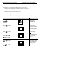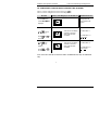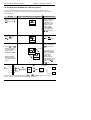
1
Installation and Operation Handbook Contents MODEL 2216e TEMPERATURE CONTROLLER INSTALLATION AND OPERATION HANDBOOK Contents Page Chapter 1 OPERATION ............................................................. 1-1 Chapter 2 INSTALLATION Chapter 3 ACCESS LEVELS Chapter 4 TUNING Chapter 5 CONFIGURATION Chapter 6 USER CALIBRATION Chapter 7 ALARM CONFIGURATION Appendix A UNDERSTANDING THE ORDERING CODE Appendix B SAFETY & EMC INFORMATION ............................ B-1 TECHNICAL SPECIFICATION ............................ B-6 Appendix C ADDRESS ............................ C-1 Appendix D VALVE POSITIONER ............................ D-1 Appendix E LOAD CURRENT MONITORING ………………… E-1 Appendix F RETRANSMISSION ………………… F-1 ........................................................... 2-1 ...................................................... 3-1 ..................................................................... 4-1 ...................................................... 5-1 ................................................. 6-1 ......................................... 7-1 ............. A-1 “This product is covered by one or more of the following US Patents: 5,484,206 and 5,793,754; Additional patents pending. PDSIO is a registered trademark of Eurotherm. INSTANT ACCURACY™, SSRx Load Doctor™ and SSRx Enhanced Load Doctor™ are trademarks of Eurotherm.” HA026639 Issue 1 Jul-99. Applies to 2216e Controller software versions 3.03 i Installation and Operation Handbook Operation Chapter 1 OPERATION PAGE Front Panel Layout .................................................................. 1-2 GETTING STARTED .................................................................. 1-4 Navigation Diagram .................................................................. 1-10 Parameter Tables .................................................................. 1-12 Setting Alarm Levels .................................................................. 1-18 Diagnostic Alarms .................................................................. 1-19 2216e Controller 1-1 Installation and Operation Handbook Operation FRONT PANEL LAYOUT 2216e Output 1 OP1 Output 2 OP2 Setpoint 2 active SP2 Remote Setpoint PDSIO® REM Upper readout Lower readout Setpoint rate limit active RUN Manual mode MAN Page Button Scroll Button Down Button Up Button Fig 1-1 Model 2216e front panel layout 1-2 2216e Controller Installation and Operation Handbook Operation Button or indicator Name Explanation OP1 Output 1 OP2 Output 2 SP2 Setpoint 2 When lit, this indicates that Setpoint 2 has been selected. REM Remote Setpoint When lit, this indicates that the PDSIO® remote Setpoint input has been selected. ‘REM’ is also used to indicate that user comms is active. MAN Manual light RUN Run light When lit, it indicates that heating output is on. When lit, it indicates that cooling output is on. When lit, it indicates that manual mode has been selected When lit, it indicates that Setpoint rate limit is active. Page button Press to select a new list of parameters. Scroll button Press to select a new parameter in a list. Down button Press to decrease a value in the lower readout. Up button Press to increase a value in lower readout. Figure 1.3 Controller buttons and indicators NOTE For Valve Positioning, please refer to Appendix D ‘Motorised Valve Control’ 2216e Controller 1-3 Installation and Operation Handbook Operation GETTING STARTED Thank you for selecting the EUROTHERM 2216e controller. This section shows the principle of operation. VIEWING THE PROCESS VALUE and SETPOINT Install and wire up the controller in accordance with Chapter 2 and switch on. Following a 3 second self-test sequence, this is the display you will see, Output 1 Output 2 OP1 OP2 SP2 Rem Figure 1.4 NOTE Actual Temperature (Process Value) Required Temperature (Setpoint) The “Home Display” The display may flash an alarm message. Refer to the Parameter Tables later in this chapter for a complete list and meaning of the messages. TO ADJUST THE SETPOINT OP1 OP2 SP2 Rem Press and hold to decrease temperature and hold to Press increase temperature Figure 1.5 The lower readout shows the setpoint After 2 seconds the lower readout will ‘blink’ indicating that the new value has been accepted. For everyday use you may not need to do anymore than this. 1-4 2216e Controller Installation and Operation Handbook Operation VIEWING THE DISPLAY UNITS .05 sec. Momentarily press either button Figure 1.6 Pressing NOTE or If you get lost, pressing Home display Display Units Degrees Centigrade Degrees Farenheit Degrees Kelvin No units - Linear inputs will flash the display units for 0.5 secs and together will return you to the USE OF THE “SCROLL” BUTTON Pressing the scroll button will display the output power level. Continued pressing will display further parameters in the operator scroll list. 2nd press Output Actual output level % 3rd press Manual/Auto Actual state Keep pressing to return to Home display or select further parameters (if available) Figure 1-7 Upper readout is parameter name. Lower is value 2216e Controller 1-5 Installation and Operation Handbook Operation USE OF THE PAGE BUTTON The “PAGE” button accesses parameter LISTS. Parameters are settings in the instrument which, generally, can be changed by the user to suit the process. Examples are: Alarms, Self Tune, etc. They are found under headings called LISTS and a full set is given later in this chapter. 0.2 sec. 1st press 2nd press 3rd press Keep pressing to select more list headings continue around a continuous loop Figure 1.8 Press to choose a parameter list NOTE 1-6 The actual list headings may be longer or shorter than indicated above and you can customise this for the operator’s convenience in EDIT level, Chapter 3. 2216e Controller Installation and Operation Handbook Operation PARAMETER LISTS Press to choose a LIST - “ALARMS” is a good one. This list allows you to set the alarm trip levels. The parameters which appear in the list will vary according to the configuration of your controller. 0.2 sec. Alarm List 2nd press 1st press There are 4 alarms in the controller. The first character is the alarm number. The following three letters indicate alarm type as follows: Full Scale Low Full Scale High Deviation High Deviation Low Deviation Band Low current High current Disabled alarms will not be displayed. Chapter 7 gives a full description of alarms. Now press the SCROLL button Alarm 1 or to change trip level 2nd press Alarm 2 or to change trip level Keep pressing 1. to scroll through further parameters 2. to return to list header Figure 1.9 Choose a list. Press to select a parameter NOTE If, at any time, no key is pressed within 45 seconds, the display will always return to the “HOME” display. 2216e Controller 1-7 Installation and Operation Handbook Operation OPERATING MODES The controller can be used in two modes: Automatic mode - in which the output power is automatically adjusted to hold the temperature at the required value. The controller normally operates in this mode. Manual mode - in which the output is manually adjusted by the Operator. In this mode the ‘MAN’ light will be on. Unit must be in full access to see ‘MAN’. One other mode is available: Remote setpoint - The setpoint is generated as an input signal from a master 2000 series controller. In this mode the REM light is on. AUTO or MANUAL SELECT 2 sec. 1st press 2nd press Output Actual output level % 3rd press Manual/Auto or to select automatic mode manual mode Keep pressing to return to “HOME” display Figure 1.10 Auto/Manual select 1-8 2216e Controller Installation and Operation Handbook Operation MANUAL ADJUSTMENT OF OUTPUT POWER OP2 OP1 OP1 OP2 OP1 Actual Temperature (Process Value) Output Power Demand REM Manual Indicator on MAN Press and hold to decrease power and hold to Press increase power Figure 1.11 The “Home Display” in manual mode NOTE Manual mode is generally used for test and commissioning purposes, take care not to leave the controller in this mode since damage or personal injury could occur. SUMMARY To step through list headers press the Page button until the required header is obtained To step through parameters within a particular list press the Scroll button required parameter is obtained until the To change the value (or state) of a parameter press the Raise button or the Lower button The remainder of this chapter provides a complete list of all parameters available. 2216e Controller 1-9 Installation and Operation Handbook Operation NAVIGATION DIAGRAM (Part A) Home List Alarm List (1) Autotune List PID List Setpoint List !4 2 2 8 "9 2 2 %&' 8 8 3 5 3 #$ The navigation diagram shows a full list of possible parameters. However, some may not appear because they are dependent upon the particular controller variant. 3 $() 3 8 * Figure 1.12a Navigation diagram 8 1-10 2216e Controller Installation and Operation Handbook Operation NAVIGATION DIAGRAM (Part B) Input List Output List On Off (1) List Comms List Access List %& $ %& * 7 7 & +7 + & ! Return to Home Display 6 Notes: 1. Either the PID list or the On/Off list will be present depending upon the type of control in use. 2. The last three characters depend upon the type of alarm configured 3. Absolute setpoint limits are set in configuration, see Chapter 5. 4. VPOS only for VP. Refer to VP Appendix D. 5. Amps is Mode 2 or Mode 5 PDSIO. 6. mtr used for VP version. Refer to VP Appendix D. 7. Beware! Used for calibration. See chapter 6. 8. Is only available if using PDSIO® comms in the HA slot. 9. WSP is available if using ramp to setpoint. The shaded boxes are normally hidden in Operator level. To see all the available parameters you must select Full level. See Chapter 3, Access Levels Figure 1.12b Navigation diagram 2216e Controller 1-11 Installation and Operation Handbook Operation PARAMETER TABLES Name Parameter Description Default Value UK USA Minimum Value Maximum Value Units % of mtr % as display as display Amps Customer Setting Home List Home Measured Value and Setpoint(SP) Valve positioner output power % Output Level Working setpoint Setpoint Heater current (PDSIO modes 2) Auto/manual select Configure lower readout of home display SP=25°C SP=75°F Customer ID as display None, StD, AmPS, OP, stat, vPoS Additional parameters may appear in the Home display if the ‘promote’ feature has been used (see Edit Level, Chapter 3). 1-12 2216e Controller Installation and Operation Handbook Name Parameter Description Alarm List Alarm 1 set point value Alarm 2 set point value Alarm 3 set point value Alarm 4 set point value Operation Default Value UK USA Maximum Value In place of dashes, the last three characters indicate the alarm type, as follows: Full Scale High alarm Full Scale Low alarm Deviation band alarm Deviation High alarm Deviation Low alarm Low current alarm High current alarm Hysterisis Loop break time 2216e Controller Minimum Value Units Customer Setting as display as display as display as display as display as display as display as display as display Amps Amps as display secs 1-13 Installation and Operation Handbook Name Operation Parameter Description Default Value UK ! ! 1-14 Minimum Maximum Value Value USA Units Customer Settings Autotune List Self tune enable Automatic droop compensation (Manual Reset) enable (only present if is set to OFF) "! "! "! ! PID List Proportional band Integral time Derivative time Manual reset (appears when ti set to OFF) Cutback low Cutback high Relative cool gain (set 1) # # as display seconds seconds % as display as display 2216e Controller Installation and Operation Handbook Name Parameter Description Operation Default Value UK USA & ! Set Point List Select SP1 or SP2 Local or remote setpoint select Setpoint 1 value Setpoint 2 value Remote setpoint Local trim Setpoint 1 low limit Setpoint 1 high limit Setpoint 2 low limit Setpoint 2 high limit Local setpoint trim low limit Local setpoint trim high limit Setpoint rate limit Dwell time End type $ $ % % # ( ) Program control Status of program 2216e Controller Minimum Maximum Value Value Units Customer Settings SP1 SP2 Loc rmt As display range As display range As display range As display range As display range As display range As display range As display range As display range As display range As display range 0.1 to 999.9 minutes ' ' !' 1-15 Installation and Operation Handbook Name Parameter Description Operation Default Value UK USA Minimum Maximum Value Value Units Customer Settings Input list secs # # Off* as display PV Offset The next 5 parameters will appear if User calibration has been enabled in configuration level. To perform a user calibration refer to Ch 6. FACt will re-instate factory settings and disable User Calibration. Default setting FACt USEr will re-instate any previously set User Calibration offsets and make available User Calibration parameters as follows: none none Hi, Lo, none User calibration select Adjust calibrated reference source * The following two parameters are always present in Full Access level but not in Operator level Cold Junction compensation temperature + Millivolt input , * Input filter time constant Do not make adjustments to the * parameter unless you wish to offset the controller calibration. 1-16 2216e Controller Installation and Operation Handbook 1 - ! 1 - 1 ! Output list Operation Note; If On/Off control is configured only Low (power) output limit High (power) output limit Output setting when in sensor break Heat cycle time Heat output min. on time Cool cycle time Cool output min. on time VP motor travel time , ! and ! will appear in the following list (cool) % % % (logic) (relay) secs secs (50mS) (logic) (relay) secs secs (50mS) * A minimum filter time of 1.0 seconds is recommended to provide sufficient noise immunity. 1 Are not used for value position control. 2216e Controller 1-17 Installation and Operation Handbook Name Operation Parameter Description Default Value UK !. Minimum Maximum Value Value USA Customer Settings On/off list This set of parameters only appear if On/Off control has been configured /- Heat hysteresis /- Cool hysteresis Heat/Cool dead band C omms list ( Access list ! 1-18 Units $ Goto level ''' ! Configuration level password Communications address Full and Edit level password ! as display as display as display 2216e Controller Installation and Operation Handbook Operation SETTING ALARM LEVELS Up to 4 Alarms may be configured. Each alarm is given a name to describe its function - see table below: If an alarm is not used it does not appear in the list below. Alarm List Alarm 1 or to change 2nd press In place of dashes, letters indicate alarm type as follows: Full Scale Low Full Scale High Deviation Band Deviation High Deviation Low Low current High current Alarm 2 or to change 3rd press Alarm 3 or to change 4th press Alarm 4 or to change 5th press Loop break time or to change Press to return to list header 2216e Controller 1-19 Operation Installation and Operation Handbook Diagnostic alarms These indicate that a fault exists in either the controller or the connected devices. Display shows What it means What to do about it Electrically Erasable Memory Error: The value of an operator or configuration parameter has been corrupted. This fault will automatically take you into configuration level. Check all of the configuration parameters before returning to operator level. Once in operator level, check all of the operator parameters before resuming normal operation. If the fault persists or occurs frequently, contact Eurotherm Controls. Sensor Break: Input sensor is unreliable or the input signal is out of range. Check that the sensor is correctly connected. Loop Break: The feedback loop is open circuit. Check that the heating and cooling circuits are working properly. Load failure Indication that there is a fault in the heating circuit or the solid state relay. This is an alarm generated by feedback from a Eurotherm TE10S solid state relay (SSR) operating in PDSIO® SSRx Load Doctor-see Electrical installation Chapter 2. It indicates either an open or short circuit SSR, blown fuse, missing supply or open circuit heater. Solid state relay failure Indication that there is a fault in the solid state relay This is an alarm generated by feedback from a Eurotherm TE10S solid state relay (SSR) operating in PDSIO® SSRx Enhanced Load Doctor-see Electrical installation Chapter 2. It indicates either an open or short circuit condition in the SSR. Heater failure Indication that there is a fault in heating circuit This is an alarm generated by feedback from a Eurotherm TE10S solid state relay (SSR) operating in PDSIO® SSRx Enhanced Load Doctor -see Electrical installation Chapter 2. It indicates either a blown fuse, missing supply or open circuit heater. Hardware error Indication that a module is of the wrong type, missing or faulty Check that the correct modules are fitted. Figure 1.13a Diagnostic alarms - continued on the next page 1-20 2216e Controller Installation and Operation Handbook Operation Diagnostic alarms continued These indicate that a fault exists in either the controller or the connected devices. Display shows What it means What to do about it No I/O module Modules are configured but not fitted Fit module Remote input failure. The PDSIO® input is open circuit (PDSIO modes also known as SST Smart Setpoint Transmission) Check for open or short circuit wiring on the PDSIO® input Out of Display range, low reading Check the value of the display range Out of Display range, high reading Check the value of the display range Error 1: ROM self-test fail Return the controller for repair Error 2: RAM self-test fail Return the controller for repair Error 3: Watchdog fail Return the controller for repair Error 4: Keyboard failure Stuck button, or a button was pressed during power up. Switch the power off and then on without touching any of the controller buttons. Error 5: Input circuit failure Return the controller for repair* Power failure. The line voltage is too low Check that the supply to the controller is within the rated limits Figure 1.13b Diagnostic alarms * If the user has disassembled and reassembled the instrument, this error can occur if any connectors are not seated properly. 2216e Controller 1-21 Installation and Operation Handbook Installation Chapter 2 INSTALLATION PAGE Instrument Layouts ....................................................... 2-2 Introduction ....................................................... 2-4 Mechanical Installation ....................................................... 2-4 Wiring ....................................................... 2-5 Outputs 1 and 2 Connection ....................................................... 2-7 Communication Connections ....................................................... 2-8 Typical Wiring Diagram ....................................................... 2-10 2216e Controller 2-1 Installation Installation and Operation Handbook INSTRUMENT LAYOUT 7 8 6 8 5 4 2 1 2 3 4 KEY 1. Display screen 2. Latching ears 3. Panel sealing gasket 4. Panel retaining clips 5. Label 6. Sleeve 7. Terminal covers 8. Ratchets Figure 2-1 2-2 2216e 1/16 DIN controller 2216e Controller Installation and Operation Handbook Installation Outline dimensions Model 2216e 103mm (4.01in) 48mm (1.89in) 2204 OP1 OP2 OP1 OP2 48mm 1.89in SP2 Re SP2 REM Panel cutout IP65, panel sealing gasket 45 x 45 -0 +0.8mm 1.77 x 1.77 -0 +0.03in 10mm Recommended (0.4in) minimum spacing of controllers 38mm (1.5in) (Not to scale) Figure 2-2 Outline dimensions Model 2216e controller The controller plugs into a plastic sleeve, which in turn fits into the panel cutout shown above. 2216e Controller 2-3 Installation Installation and Operation Handbook INTRODUCTION The Model 2216e is a precision temperature controller with self tuning. It has a modular hardware construction which provides two control outputs, one alarm relay and one communications port. Controller labels The labels on the sides of the controller identify the ordering code, the serial number, and the wiring connections. Appendix A, Understanding the Ordering Code explains the hardware and software configuration of your particular controller. MECHANICAL INSTALLATION To install the controller 1. Cut the panel to the relevant hole size shown in Figure 2-3 and 2.4. 2. Insert the controller through the front of this cutout. 3. Spring the upper and lower panel retaining clips into place. Secure the controller in position by holding it level and pushing both retaining clips forward. NOTE If the panel retaining clips subsequently need removing, they can be unhooked from the side with either your fingers or a screwdriver Unplugging and plugging-in the controller The controller can be unplugged from its sleeve by easing the latching ears outwards and pulling it forward out of the sleeve. When plugging the controller back into its sleeve, ensure that the latching ears click into place to maintain the IP 65 sealing. 2-4 2216e Controller Installation and Operation Handbook Installation WIRING Please read Appendix B, Safety and EMC information before proceeding. WARNING Please ensure that the controller is correctly configured for your application. Incorrect configuration could result in damage to the process being controlled, and/or personal injury. The controller may either have been configured when ordered, or may need configuring now. See Chapter 5, Configuration. HA L 85-264Vac 1B HB N Neutral 2A HC 2B HD VI 3A Comms HE V+ 3B HF V- Output 1 Output 2 Line 1A Ground* Output 3 + - + PV Pt100 Figure 2-3 Model 2216e wiring connections * The ground connection is not required for electrical safety but must be connected to satisfy EMC requirements. Wire Sizes All electrical connections are made to the screw terminals at the rear of the controller. They 2 accept wire sizes from 0.5 to 1.5 mm (16 to 22 AWG), and are protected by a hinged cover to prevent hands or metal making accidental contact with live wires. Rear terminals should be tightened to a torque of 0.4Nm (3.5 lb in). Wiring connections The wiring connections are shown in Figure 2-3. Outputs 1 and 2 are factory fitted modules which can be any one of the types shown in figure 2-8. Check the ordering code on the controller side label to determine which have been fitted. 2216e Controller 2-5 Installation Installation and Operation Handbook Sensor input connections The connections for the various types of input are as follows: Thermocouple Resistance thermometer VI VI VI V+ V+ V+ V- V- V- NOTE Volts or mV inputs mA input VI 2.49Ω current sense resistor V+ + V- - PV Sensor inputs should not be paralleled. Fig 2-7 Sensor input connections OUTPUTS 1 AND 2 CONNECTIONS Outputs 1 and 2 can be any one of the types shown in the table below, configured to perform any one of the functions shown. To check which outputs are installed, and their configuration, refer to the ordering code and the wiring information on the controller side labels. Connections Output 1 1A Module type Output 2 1B 2A Possible functions 2B Heating Cooling Alarms Relay: 2-pin (2A, 264 Vac max.) Logic: non-isolated* (18Vdc at 24mA) + - + - +PDSIO® modes 1or 2 (SSRx Load Doctor Functions) Heating Cooling Alarms Triac (1A, 30 to 264Vac) Heating or cooling Line DC control: isolated (18Vdc, 20mA max) + Load - Line Load DC not available in output 2 PID Heating or cooling *Logic can also be configured as logic input on module 2A. +PDSIO® Mode 1 & 2 are only supported in Output 1. Figure 2-8 Outputs 1 and 2 connections 2-6 2216e Controller Installation and Operation Handbook Installation PDSIO® modes PDSIO® is a proprietary technique developed by Eurotherm for bi-directional communication over a single pair of wires. There are several operating modes. In SSRx Load Doctor a logic output delivers a power demand signal to a TE10 solid state relay (SSR) and the SSR responds with a single load circuit failure message. In SSRx Enhanced Load Doctor a logic output delivers a power demand signal to an SSR and the SSR responds with the ON state RMS load current, and two fault messages - SSR failure or heater circuit failure. Snubbers The controller is supplied with ‘snubbers’ (15nF +100Ω) which should be wired across the relay or triac outputs when switching inductive loads such as mechanical contactors and solenoid valves. The snubbers are used to prolong contact life and to suppress interference when switching such loads. Snubbers pass 0.6mA at 110Vac and 1.2mA at 240Vac, which may be sufficient to hold in high impedance relay coils. They should not, therefore, be used in such installations. WARNING When a relay contact is used in an alarm circuit ensure that the current passing through the snubber when the relay contact is open does not hold in low power electrical loads and thereby interfere with the failsafe operation of the alarm circuit. COMMUNICATION CONNECTIONS The communication option can be either of four types shown in the table below Connection Communications type HB HC HD HE HF A’ (RX +) B’ (RX -) Common A (TX +) B (TX -) EIA-232 serial communications Not used Not used Common A B PDSIO™ Setpoint input (SST) Not used Not used Not used Signal Common Common A (TX +) (RX +) B (TX -) (RX -) 4-wire EIA-422 serial communications* 2-wire EIA-485 Serial Communications Not used Not used Figure 2-9 Communication connections *The 4-wire EIA-422 communication board can be modified to support 2-wire 485 communication. Please consult factory. 2216e Controller 2-7 Installation Installation and Operation Handbook Wiring of EIA-485 serial communication links PC Com TX RX RX TX Standard EIA-485 is a 2-wire connection which allows up to 32 controllers to be multi-dropped from a single communications link over a distance of up to 1.2Km. To ensure reliable operation of the communications link, (without data corruption due to noise or line reflections) the connections between the controller should be made using a twisted pair of wires inside a shielded cable with the connections terminated with resistors in the manner shown in this diagram. This diagram also shows the use of a converter to connect the 2-wire EIA-485 link into a standard EIA232 computer port. L ocal E arth 232 Com Univers al Convertor Com B A A B HE HF + Com HD S eries 2000™ Controller L ocal E arth S eries 2000™ Controller A B Com A MMI Univers al B Converter Com A B Com HE HF + HD L ocal E arth Galvanic Is olation Barrier Up to 32 controllers or Interface Units may be included on the network A B Com F or s afety reas ons , do not connect to local earth here. HE HF + HD S eries 2000™ Controller Note: All termination res is tors are 220 ohm 1/4W carbon compos ition. L ocal grounds are at equipotential. Where equipotential is not available wire into s eparate zones us ing a galvanic is olator. Figure 2-10 2-wire EIA-485 wiring 2-8 2216e Controller Installation and Operation Handbook Installation TYPICAL WIRING DIAGRAM Cooling Power Fuse 1A(T) Line Neutral Controller Fuse 2A(T) Snubber 1A HA L 1B HB N 2A HC 2B HD V1 3A Comms HE V+ 3B HF V- Thermocouple - Solid State Heating power fuse (load dependent) Relay such as + TE10S Cooling Solenoid Valve Heater Fig 2-8 Typical wiring diagram, Model 2216e Controller 2216e Controller 2-9 Installation and Operation Handbook Access Levels Chapter 3 ACCESS LEVELS PAGE The Different Access Levels .......................................................... 3-2 Selecting an Access Level .......................................................... 3-3 Edit Level .......................................................... 3-5 2216e Controller 3-1 Access Levels Installation and Operation Handbook This chapter describes the different levels of access to the operating parameters within the 2208e and 2204e controller. There are three topics: • THE DIFFERENT ACCESS LEVELS • SELECTING AN ACCESS LEVEL • EDIT LEVEL THE DIFFERENT ACCESS LEVELS Access level Display shows What you can do Password Protection Operator In this level operators can view and adjust the value of parameters defined in Edit level (see below). No Full In this level all the parameters relevant to a particular configuration are visible. All alterable parameters may be adjusted. Yes Edit In this level you can set which parameters an operator in Operator level is able to view and adjust. You can hide or reveal complete lists and individual parameters within each list, and you can make parameters read-only or alterable. You can also promote parameters to the home list. (See Edit level at the end of the chapter). Yes Configuration This special level allows access to set up the fundamental characteristics of the controller. Yes Figure 3-1 Access levels 3-2 2216e Controller Installation and Operation Handbook Access Levels SELECTING AN ACCESS LEVEL Access to Full, Edit or Configuration levels is protected by a password to prevent unauthorised access. If you need to change the password, see Chapter 5, Configuration Access list header Press until you reach the access list header ‘’. Press the Scroll button Password entry The password is entered from the ‘ display. Enter the password using the or buttons. Once the correct password has been entered, there is a two second delay after which the lower readout will change to show ‘ indicating that access is now unlocked. The pass number is set to ‘1’ when the controller is shipped from the factory. Note; A special case exists if the password has been set to ‘’. In this case access will be permanently unlocked and the lower readout will always show ‘’ Press the Scroll button to proceed to the display. (If an incorrect password has been entered and the controller is still ‘locked’ then pressing Scroll at this point will simply return you to the list header.) Note: From this display, you can access “read only” together. configuration level by pressing and To escape, press 2216e Controller and together. 3-3 Access Levels Installation and Operation Handbook Level selection The display allows you to select the required access level. Use codes: and to select from the following display Operator level : Full level Edit level : Configuration level Press the Scroll button . If you selected either ‘, or level you will be returned to the ‘ list header in the level that you chose. If you selected ‘’, you will get an alternative display showing ‘’ in the upper readout (see below). Configuration password When the ‘’ display appears, you must enter the Configuration password in order to gain access to Configuration level. Do this by repeating the password entry procedure described in the previous section The configuration password is set to ‘’ when the controller is shipped from the factory. If you need to change the configuration password, see Chapter 5, Configuration Press the Scroll button Configuration level . 3-4 The first display of configuration is shown. See chapter 5, Configuration for details of the configuration parameters. For instructions on leaving configuration level see Chapter 5, Configuration. 2216e Controller Installation and Operation Handbook Access Levels Returning to Operator Level To return to operator level from either ‘’ or ‘’ level, repeat entry of the password and select ‘’ on the ’’ display. In ‘Edit’ level the controller will automatically return to operator level if no button is pressed for 45 seconds. EDIT LEVEL Edit level is used to set which parameters you can see and adjust in Operator level. It also gives access to the ‘Promote’ feature which allows you to select and add (‘Promote’) up to twelve parameters into the Home display list, thereby giving simple access to commonly used parameters. Setting operator access to a parameter First you must select level, as shown on the previous page. Once in level you select a list or a parameter within a list in the same way as you would in Operator or Full level. Τhat is, you move from list header to list header by pressing the Page button, and from parameter to parameter within each list using the Scroll button. However, in Edit level what is displayed is not the value of a selected parameter but a code representing the parameter’s availability in Operator level. and buttons to set its When you have selected the required parameter, use the availability in operator level. There are four codes: Makes a parameter alterable in Operator level Promotes a parameter into the Home display list Makes a parameter or list header read-only (it can be viewed but not altered) Hides a parameter or list header. For example: 2216e Controller The parameter selected is the set point for Alarm 2 - Full Scale Low It will be alterable in Operator level 3-5 Access Levels Installation and Operation Handbook Hiding or revealing a complete list To hide a complete list of parameters, all you have to do is hide the list header. If a list header is selected only two selections are available: and . (It is not possible to hide the ‘’ list which will always display the code: ‘’.) Promoting a parameter Scroll through the lists to the required parameter and choose the ‘’ code. The parameter is then automatically added (promoted) into the Home display list (the parameter will also be accessible as normal from the standard lists. a maximum of 16 parameters can be promoted. Promoted parameters are automatically ‘alterable’. 3-6 2216e Controller Installation and Operation Handbook Tuning Chapter 4 TUNING PAGE What is Tuning? .................................................................. 4-2 Automatic Tuning .................................................................. 4-3 Manual Tuning .................................................................. 4-6 2216e Controller 4-1 Tuning Installation and Operation Handbook Before tuning please read Chapter 1, Operation, to learn how to select and change a parameter. This chapter has three main topics: • WHAT IS TUNING? • AUTOMATIC TUNING • MANUAL TUNING WHAT IS TUNING? In tuning you match the characteristics of the controller to that of the process being controlled in order to obtain good control. Good control means: Stable ‘straight-line’ control of the temperature at setpoint without fluctuation Acceptable overshoot or undershoot of the temperature setpoint Quick response to deviations from the setpoint caused by external disturbances, thereby restoring the temperature rapidly to the setpoint value. Tuning involves calculating and setting the value of the parameters listed in Table 4-1. These parameters appear in the list. Parameter Code Meaning or Function Proportional band The bandwidth in display units over which the output power is proportioned between minimum and maximum. Integral time Determines the time taken by the controller to remove steadystate error signals. Derivative time Determines how strongly the controller will react to the rate-ofchange of the measured value. Low cutback The number of display units below setpoint at which the controller will cutback the output power in order to prevent overshoot on heat up. High Cutback The number of display units above setpoint at which the controller will increase the output power in order to prevent undershoot on cool down. Relative cool gain Only present if cooling has been configured. Sets the cooling proportional band by dividing the Pb value by the rEL.C value. Table 4-1 Tuning parameters 4-2 2216e Controller Installation and Operation Handbook Tuning AUTOMATIC TUNING This method automatically determines the value of the parameters listed in table 4-1 on the previous page. The 2216e uses a ‘one-shot’ tuner which works by switching the output on and off to induce an oscillation in the measured value. From the amplitude and period of the oscillation, it calculates the tuning parameter values. If the process cannot tolerate full heating or cooling being applied during tuning, then the level of heating or cooling can be restricted by setting the heating and cooling power limits in the Output list. However, the measured value must oscillate to some degree for the tuner to be able to calculate values A One-shot Tune can be performed at any time but normally it is performed only once during the initial commissioning of the process. However, if the process under control subsequently becomes unstable (because its characteristics have changed), you can re-tune again for the new conditions. It is best to start tuning with the process at ambient temperature. This allows the tuner to calculate more accurately the low cutback and high cutback values that restrict the amount of overshoot or undershoot. Heating and Cooling Output Cycle Times Before commencing a tuning cycle, set the values of (heat cycle time) and (cool cycle time) in the op (output list). These values apply if you are using a logic, relay or triac output. They have no effect on a DC output. A logic output switching a solid state relay can be set to values such as 1 sec. A relay or triac output should be set to 20 sec. 2216e Controller 4-3 Tuning Installation and Operation Handbook How to tune 1. 2. Set the setpoint to the value at which you will normally operate the process. In the ‘ ’ list, select ‘ ’ and set it to ‘’ 3. Press the Page and Scroll buttons together to return to the Home display. The display will flash ‘ ’ to indicate that tuning is in progress. 4. The controller will induce an oscillation in the temperature by turning the heating on and then off. The first cycle will not complete until the measured value has reached the required setpoint. 5. After two cycles of oscillation the tuning will be completed and the tuner will switch itself off. 6. The controller will then calculate the tuning parameters listed in Table 4-1 and will resume normal control action. If you want ‘Proportional only’ or ‘PD’ or ‘PI’ control, you should set the ‘’ or ‘’ parameters to before commencing the tuning cycle. The tuner will leave them off and will not calculate a value for them. For valve position tuning and set-up, please refer to Appendix D. 4-4 2216e Controller Installation and Operation Handbook Tuning Typical automatic tuning cycle Temperature Setpoint Time Calculation of the cutback values Low cutback and High cutback are values that restrict the amount of overshoot or undershoot that occur during large step changes in temperature (for example, under startup conditions). If either low cutback or high cutback is set to ‘ ’ the values will be fixed at three times the proportional band, and will not be changed during automatic tuning. 2216e Controller 4-5 Tuning Installation and Operation Handbook MANUAL TUNING If for any reason automatic tuning gives unsatisfactory results, you can tune the controller manually. There are a number of standard methods for manual tuning. The one described here is the Ziegler-Nichols method. With the process at its normal running temperature: Set the Integral Time ‘ and the Derivative Time ‘’ to 2. . Set High Cutback and Low Cutback, ‘’ and ‘’, to ‘ ’ 3. Ignore the fact that the temperature may not settle precisely at the setpoint 1. If the temperature is stable, reduce the proportional band ‘’ so that the temperature just starts to oscillate. If the temperature is already oscillating, increase the proportional band until it just stops oscillating. Allow enough time between each adjustment for the loop to stabilise. Make a note of the proportional band value ‘B’ and the period of oscillation ‘T’. 4. 5. Set the Pb, ti, td parameter values according to the calculations given in Table 4-2. Type of control Proportional band ‘Pb’ Integral time ‘ti’ Derivative time ‘td’ Proportional only 2xB OFF OFF P + I control 2.2xB 0.8xT OFF P + I + D control 1.7xB 0.5xT 0.12xT Table 4-2 Tuning values 4-6 2216e Controller Installation and Operation Handbook Tuning Setting the cutback values The above procedure sets up the parameters for optimum steady state control. If unacceptable levels of overshoot or undershoot occur during start-up or for large step changes in temperature, then manually set the cutback parameters and . Proceed as follows: 1. Set the low and high cutback values to three proportional bandwidths (that is to say, Lcb = Hcb = 3 x Pb). 2. Note the level of overshoot or undershoot that occurs for large temperature changes (see the diagrams below). In example (a) increase by the overshoot value. In example (b) reduce by the undershoot value. Example (a) Temperature Overshoot Setpoint Example (b) Temperature Undershoot Time Where the temperature approaches setpoint from above, you can set a similar manner. 2216e Controller in 4-7 Tuning Installation and Operation Handbook Integrating action and manual reset In a full three-term controller (that is, a PID controller), the integral term ‘ti’ automatically removes steady state errors from the setpoint. If the controller is set up to work in two-term mode (that is, PD mode), the integral term will be set to . Under these conditions the measured value may not settle precisely at setpoint. When the integral term is set to OFF the parameter manual reset (code ) appears in the in ‘ ’ Access level. This parameter represents the value of the power output that will be delivered when the error is zero. You may set this value manually in order to remove the steady state error. Automatic droop compensation (Adc) The steady state error from the setpoint, which occurs when the integral term is set to OFF, is sometimes referred to as ‘droop’. automatically calculates the manual reset value in order to remove this droop. To use this facility, you must first allow the temperature to stabilise. Then, in the autotune parameter list, you must set to ‘’. The controller will then calculate a new value for manual reset, and switch to ‘’. can be repeated as often as you require but between each adjustment you must allow time for the temperature to stabilise. 4-8 2216e Controller Installation and Operation Handbook Configuration Chapter 5 CONFIGURATION PAGE Selecting Configuration Level Leaving Configuration ...................................................... 5-2 ................................................................... 5-3 Steps Involved in Configuring a Controller Navigation Diagram .................................... 5-3 ...................................................................... 5-4 Configuration Parameter Tables .................................................. 5-6 WARNING Configuration is protected and should only be carried out by an authorised person. Incorrect configuration could result in damage to the process being controlled and/or personal injury. It is the responsibility of the person commissioning the instrument to ensure that the configuration is correct. 2216e Controller 5-1 Configuration Installation and Operation Handbook SELECTING CONFIGURATION LEVEL “HOME” display Press Page button repeatedly until Access List appears If incorrect password entered 1st press 2 secs If the password has been set to ‘’ - access or to enter password is permanently (factory default = 1) unlocked & the lower readout always shows 2nd press or to select Note: Selecting or will allow direct entry to these levels at this point 3rd press or to enter password (factory default = 2) At this point the controller is in configuration level 4th press Repeated pressing of “Page” button selects configuration list headings in a continuous loop Figure 5.1 5-2 2216e Controller Installation and Operation Handbook Configuration LEAVING CONFIGURATION LEVEL Keep pressing until Exit display appears or to select After a 2 second delay the screen will blank, the instrument will reset, and revert to the Home display Figure 5.2 STEPS INVOLVED IN CONFIGURING A CONTROLLER The navigation diagram which follows shows the general location of parameters which define the way in which the controller works. They are grouped under headings. The actual parameters shown in your controller may differ slightly since some appear only as a result of selecting others. A full list of possibilities is included in the PARAMETER TABLES which follow the navigation diagram. 2216e Controller 5-3 Configuration Installation and Operation Handbook NAVIGATION DIAGRAM (PART A) Instrument Config Input Config User cal. Config Alarms Config ° & % ! # ! & " The Principle of Operation is the same as that already described in Ch1. That is: $ ' ! Step through List Headers using the ‘Page’ button $ & Choose a parameter from a list using the ‘Scroll’ button * *! () % Change value using the ‘Raise/Lower’ buttons # ! The first 4 headings set up the controller functions, as follows: Instrument Config. - Groups those parameters associated with the display and control action. Input Config. - selects the input sensor type User cal. Config. - to calibrate to external reference sources Alarms Config. - sets up the alarm types & 5-4 2216e Controller Installation and Operation Handbook Configuration NAVIGATION DIAGRAM (PART B) Comms Config Output 1 Config Output 2 Config Output 3 Config ' 10A output Config # Password Config ( ! + + + % ( % , % !! % % &-% ./ !% 0 %1 !% $- $- See Table B parameter table, page 513 See Table B parameter table, page 513 2216e Controller 5-5 Configuration Installation and Operation Handbook Heading Input/Output Functions Wiring Terminals The first four headings set up the controller functions as follows: Sets up display and control parameters Not applicable Selects the input sensor type Not applicable To calibrate to external reference sources Not applicable Sets up the alarm types Not applicable The remaining headings configure the controller input/output functions. The upper readout corresponds to rear terminal numbers associated with a particular i/o. LA & LB Sets up the action of the two digital inputs Sets up the action of the fixed relay on output AA AA to AC Sets up digital comms type HB to HF Sets up the output modules 1A and 2A 1A & 1B / 2A & 2B Sets up the action of the fixed relay on output 3A 3A to 3C Sets the action of the 10A output relay in 2204 4A to 6D To choose new passwords To leave configuration level and return to operator level / 5-6 2216e Controller Installation and Operation Handbook Configuration CONFIGURATION PARAMETER TABLES Name Parameter description % Instrument configuration Decimal places in the displayed value Control type Control action Type of cooling " Power feedback ! Bumpless manual/auto transfer when using PD control ! Forced manual output 4 * Sensor break output *! Instrument units Values Meaning 2 2 23 ! ) Centigrade (default UK) Fahrenheit (default USA) Kelvin Units are not displayed None One Two On/off control PID control VP Control Reverse acting (required for temperature control) - output decreases on approach to setpoint. Direct acting Linear Oil (50mS min on time) Water(non-linear) Fan (0.5S min on time) Power feedback is on (compensates for changes in supply voltage) Power feedback is off Non-bumpless transfer Bumpless transfer (auto to manual and manual to auto) Bumpless manual/auto transfer Returns to the manual value that was set when last in manual mode. Go to pre-set value (maintains output at a known, safe level) Freeze output (maintains output at value immediately before break) See Appendix E-10 NOTE Load Current Scaling Factor Factory default parameter values and states are included where applicable and are indicated by the shaded areas in the following tables. 2216e Controller 5-7 Configuration Installation and Operation Handbook Name Parameter description Input configuration Input type NOTE: After selecting an input type, do not forget to adjust the setpoint limits in Full Access level Value * ($ Input range low Input range high CJC ref. temperature (CJC does not appear for linear inputs) % 2 #52 52 Meaning J thermocouple (default USA) K thermocouple (default UK) L thermocouple R thermocouple (Pt/Pt13%Rh) B thermocouple (Pt30%Rh/Pt6%Rh) N thermocouple T thermocouple S thermocouple (Pt/Pt10%Rh) PL 2 thermocouple 100Ω platinum resistance thermometer. Custom downloaded input type. The default is C thermocouple, or the name of the downloaded custom input will be displayed. Linear millivolt (Also mA input via an external 2.49Ω current sense resistor) Linear voltage Display low range for input Display high range for input Automatic cold junction compensation 0°C external reference 45°C external reference 50°C external reference Linear Input Scaling - The next 4 parameters only appear if a linear input is chosen Input value low Displayed Value Input value high $ $ Displayed reading low ( Sensor break input impedance trip level Electrical Input ! % 5-8 Displayed reading high Sensor break detection is disabled Appears for mV or V inputs only Trip level set by the sensor input table Trip level set at 7.5KΩ Trip level set at 15KΩ (must be selected when input is enabled) 2216e Controller Installation and Operation Handbook Name Parameter description User calibration config. User calibration point low User calibration point high Low point calibration offset ! ! Configuration User cal enable High point calibration offset Value Meaning See Chapter 6 - User calibration User calibration is disabled User calibration is enabled This is the value (in display units) at which a User last performed a low point calibration This is the value (in display units) at which a User last performed a high point calibration Offset, in display units, at the user low calibration point ‘Pnt.L’. This value is automatically calculated when performing low point calibration. Offset, in display units, at the user high calibration point ‘Pnt.H’. This value is automatically calculated when performing a high point calibration. * If User calibration is enabled, then the User calibration parameters will appear in the Input list of Operator Full access level. See Chapter 6, User calibration. 2216e Controller 5-9 Configuration Installation and Operation Handbook Name Parameter description * * ' * # * Alarm configuration Values Defaults if not specified Alarm 1 Type (1) Alarm 1 Blocking As table A ! ! ! ! Alarm 1 Latching Alarm 2 Type (1) Alarm 2 Blocking Alarm 2 Latching Alarm 3 Type (1) Alarm 3 Blocking Alarm 3 Latching Alarm 4 Type (1) Alarm 4 Blocking Alarm 4 Latching Values / /%/(- As table A / /%/(- As table A / /-%/(- As table A / /-%/(- Table A: Alarm types ! No alarm Full scale low Full scale high Deviation band Deviation high Deviation low Low current High current (1) Blocking allows the alarm to become active only after it has first entered a safe state. NOTE 5-10 These are ‘soft’ alarms, i.e. Indication only. They would normally be attached to an output. See Chapter 7 for a step by step guide. 2216e Controller Installation and Operation Handbook Name Parameter description Configuration Functions Meaning Comms module config Functions Meaning Identity of the option installed ( PDSIO® setpoint input 2- or 4-wire EIA-485 (422) or EIA-232 comms module % Function Some of the following parameters may appear if one of the comms options is installed ( DIGITAL Communication protocol ordered None The following parameters will appear if the PDSIO setpoint input option is installed. No PDSIO® function PDSIO® setpoint input PDSIO® low input value Range = -999 to 9999 $ PDSIO® high input value Range = -999 to 9999 $ The following parameters will appear if the function chosen is Mod protocol. &% *+ * Baud Rate Comms Parity 1200, 2400, 4800, 9600, 19.20, 1920 (19200) No parity Even parity Odd parity ! Comms Resolution Full resolution % Integer resolution *Not used with some communication protocols. Please consult factory. 2216e Controller 5-11 Configuration Installation and Operation Handbook Name Parameter description Function Meaning Output 1 configuration Identity of module installed Function % Function Meaning No module fitted Relay output DC output (isolated) Logic or PDSIO® output Triac output Module does not operate Function set by Heating output Cooling output Retransmission of output demand Retransmission of Process Value Retransmission of error Retransmission of setpoint PDSIO® mode heating PDSIO® mode 2 heating Only appear for id = dC.OP 0+ ! 6 !! ! Only appear for id = dC.OP $ Only appear for id = dC.OP Only appear for id = dC.OP Only appear for id = LoG Only appear for id = LoG " For 7%tion = go to table B below Sense of output Normal (e.g.heating and cooling) Inverted (alarms - de-energise in alarm) DC output scaling For id = dC.OP the following parameters appear DC output minimum 0mA to 20mA !% DC output maximum 0mA to 20mA !% 5-12 2216e Controller Installation and Operation Handbook Configuration Table B The following parameters appear if ‘’ is chosen as the function. Digital output functions Any number of the functions listed can be combined on to the output. Use the and buttons to select a desired digital function. After two seconds the display will blink and return to the ‘’ display. Use the arrows again to scroll through the function list. The previously selected function display will show two decimal points indicating that it has been added to the output. 8 8 8 8 ' 8 8 # 8 8 9 * * 7 6 6"- 0( ! 8* 8* 8* 8* No change Clear all existing functions Alarm 1 * Alarm 2 * Alarm 3 * Alarm 4 * Manual/Auto Sensor Break Loop Break Heater Fail Load Fail END Program PV Out of Range PDSIO® SSR Failure New Alarm Remote Sp Fail CTx open circuit Ctx short circuit * From previous page. In place of the dashes, the last three characters indicate the alarm type as per table A in the AL list: eg = Full Scale Low If an alarm is not configured the displayed name will differ: e.g. ‘ 2 will be shown, for the first alarm. Name Parameter description Function Output 2 configuration Function Meaning Identity of module installed % Function + !! ( ( * No module fitted Relay output Logic Triac output none Outputs Logic Inputs Meaning Function set by Heating output Cooling output Manual mode select Remote setpoint select Setpoint 2 select Integral hold Acknowledge alarms Standby - ALL outputs = OFF For % = (Refer to table B on page 5-13). Sense of output Normal (heat and cool outputs) Inverted (alarms - de-energise in alarm) 2216e Controller 5-13 Configuration FuLL or Edit level password Configuration level Password Exit Configuration 5-14 Installation and Operation Handbook Password list / 2216e Controller Installation and Operation Handbook User Calibration Chapter 6 USER CALIBRATION PAGE What is the Purpose of User Calibration? ................................... 6-2 User Calibration Enable ............................................................... 6-3 Single Point Calibration ............................................................... 6-4 Two Point Calibration .................................................................. 6-5 Calibration Points and Calibration Offsets 2216e Controller .................................. 6-6 6-1 User Calibration Installation and Operation Handbook This chapter has five topics: • WHAT IS THE PURPOSE OF USER CALIBRATION? • USER CALIBRATION ENABLE • SINGLE POINT CALIBRATION • TWO POINT CALIBRATION • CALIBRATION POINTS AND CALIBRATION OFFSETS To understand how to select and change parameters in this chapter you will need to have read Chapter 2 - Operation, Chapter 3- Access Levels and Chapter 5 - Configuration. WHAT IS THE PURPOSE OF USER CALIBRATION? The basic calibration of the controller is highly stable and set for life. User calibration allows you to offset the ‘permanent’ factory calibration to either: 1. Calibrate the controller to your reference standards 2. Match the calibration of the controller to that of a particular transducer or sensor input 3. Calibrate the controller to suit the characteristics of a particular installation. User calibration works by introducing zero and span offsets onto the factory set calibration. The factory set calibration can always be retrieved. 6-2 2216e Controller Installation and Operation Handbook User Calibration USER CALIBRATION ENABLE The User calibration facility must first be enabled in configuration level by setting the parameter ‘' in the list to '' This will make the User calibration parameters appear in Operator ‘’ level. Select configuration level as shown in Chapter 5, Configuration The User calibration configuration List Press until you reach the ‘ list ress the Scroll button until you reach User calibration enable Use 2216e Controller to select: : Calibration enable : Calibration disabled Press or and together to go to the Exit display Exit configuration Use or to select ‘’ and return to Operator level. 6-3 User Calibration Installation and Operation Handbook SINGLE POINT CALIBRATION Your controller is calibrated for life against known reference sources during manufacture. A calibration offset is often used to allow the controller to compensate for sensor and other system errors. The normal procedure is to set up the system under test against a known independent reference, as follows: Set up the process to be calibrated such that the known reference displays the required value (temperature). Observe the reading on the controller. If it is different, proceed as follows: Select ‘ Access level as described in Chapter 3 Input list header Press until you reach the input list header. Press Scroll until you reach the ‘’ display Calibration type Use or to select either ‘’ or ‘’. Selecting ‘’ will reinstate the factory calibration and hide the following User calibration parameters. Selecting ‘’ will reinstate any previously set User calibration and make available the User parameters, as follows: Press the Scroll button Calibrate low point? or to select ‘’ Use Selecting ‘no’ will hide the next parameter Press the Scroll button continued on the next page 6-4 2216e Controller Installation and Operation Handbook User Calibration Adjust the low point calibration The controller will display the current measured input value in the lower readout. Use or to adjust the reading to the reference source value, if different. After a two second delay the display will blink and the reading will change to the new, calibrated value. You can calibrate at any point over the entire display range This is a single point calibration which applies a fixed offset over the full display range of the controller. The calibration is now complete. You can return to the factory calibration at any time by select ‘’ in the CAL display shown earlier. Press and Home display together to return to the To protect the calibration against unauthorised adjustment return to Operator level and make sure that the calibration parameters are hidden. Parameters are hidden using the ‘’ facility describe in Chapter 3. TWO POINT CALIBRATION The previous section described how to perform a single point calibration which applies a fixed offset over the full display range of the controller. A two-point calibration is used to calibrate the controller at two points and apply a straight line between them. Any readings above or below the two calibration points will be an extension of this straight line. For this reason it is best to calibrate with the two points as far apart as possible. Proceed as follows: 1. Decide upon the low and high points at which you wish to calibrate. 2. Perform a single point calibration at the low calibration point in the manner described above 3. Set the process under calibration such that the known reference exhibits the required higher Process Value (temperature) and allow to stabilize. 4. Press the Scroll button to obtain the high calibration point as shown in the following diagrams. 2216e Controller 6-5 User Calibration Installation and Operation Handbook Calibrate high point? Use or to select ‘’ Press the Scroll button Adjust the high point calibration The controller will display the current measured input value in the lower readout. or to adjust the reading to the reference source Use value, if different. After a two second delay the display will blink and the reading will change to the new, calibrated value. The calibration is now complete. You can return to the factory calibration at any time by select ‘’ in the display shown earlier. To protect the calibration against unauthorised adjustment return to Operator level and make sure that the calibration parameters are hidden. Parameters are hidden using the ‘’ facility described in Chapter 3. CALIBRATION POINTS AND CALIBRATION OFFSETS If you wish to see the points at which the User calibration was performed and the value of the offsets introduced these are shown in Configuration, under . The parameters are: Name Parameter description User low calibration point User high calibration point Low point calibration offset High point calibration offset 6-6 Meaning This is the value (in display units) at which a User last performed an ‘’ (adjust low calibration). This is the value (in display units) at which a User last performed an ‘’ (adjust high calibration). Offset, in display units, at the user low calibration point ‘ Offset, in display units, at the user high calibration point ‘. 2216e Controller Installation and Operation Handbook Alarm Operation Chapter 7 ALARM CONFIGURATION PAGE Definition of Alarms and Events Types of Alarms ...................................................... 7-2 ................................................................................ 7-2 Step 1 - Configuring the Four ‘Soft’ Alarms .................................... 7-5 Step 2 - Attaching an Alarm to a Physical Output Step 3 - Grouping Alarms on a Single Output Step 4 - Removing Alarms from an Output .......................... 7-6 ................................. 7-7 ...................................... 7-7 The 2200e series controllers are capable of very sophisticated alarm strategies and, although setting up of alarms has already been covered in previous chapters, this section has been included to enable operators and commissioning engineers to design their own strategies for optimum plant operation. 2216e Controller 7-1 Alarm Operation Installation and Operation Handbook DEFINITION OF ALARMS AND EVENTS Alarms are used to alert an operator when a pre-set level or condition has been exceeded. They are normally used to switch an output - usually a relay - to provide interlocking of the machine or plant or external audio or visual indication of the condition. Soft Alarms are indication only within the controller and are not attached to an output (relay). Events - can also be alarms - but are generally defined as conditions which occur as part of the normal operation of the process. They do not generally require operator intervention. Events are referred to as Digital Output Functions in the manual (see Table B, page 5-13). For the purposes of the operation of this instrument alarms and events can be considered the same. TYPES OF ALARMS The use of alarms in the 2216econtroller is extremely versatile. Up to 4 alarms can be configured. Any combination of these 4 alarms can be attached to any one or more available outputs, or any number of the available “soft” alarms can be combined to operate a single output. NOTE Note: In a three term controller at least one of these outputs is used to maintain the required temperature of the process. Outputs 1A and 2A Are plug in modules. Normally used for control outputs, eg. Heat and Cool, but can be used for alarm outputs. Output 3A Is a fixed relay. Normally used for alarms or events, but can be used as control outputs. 7-2 2216e Controller Installation and Operation Handbook Alarm Operation There are seven process alarm types listed below. Alarm Types are found in configuration mode under the Alarm Config. List. ALARMS Full Scale High The PV exceeds a set high level Full Scale Low The PV exceeds a set low level Deviation Band The difference between PV & SP is outside a set band Deviation High The difference between PV & SP is higher than a set level Deviation Low The difference between PV & SP is lower than a set level High Current The measured current returned from a PDSIO® slave is higher than a set level Low Current The measured current returned from a PDSIO® slave is lower than a set level Each alarm can be set to: Latching Alarm is indicated until acknowledged (Off, Auto, MAN) Auto Acknowledge: ( ) If the alarm is acknowledged while the alarm condition is still present, it will cause the alarm to reset as soon as the alarm condition is removed. Manual Acknowledge: ( ) If the alarm is acknowledged while the alarm condition is still present, it will be ignored. A further acknowledgement is required when the alarm condition has been removed to cause the alarm to reset. Blocking Alarm occurs after it has been through a start up phase not in alarm condition. Sense Of Output Relay energised or de-energised in alarm condition. 2216e Controller 7-3 Alarm Operation Installation and Operation Handbook In addition there are nine “digital output functions” used as events or alarms depending upon the requirements of the process under control: DIGITAL OUTPUT FUNCTIONS Sensor Break` The input is open circuit Loop Break The controller does not measure a response to an output change Load Failure Used with PDSIO® Mode 1 load failure Manual Controller in manual mode PV Out Of Range Process Variable too high or too low Remote SP Fail No signal measured at the remote set point input terminals Heater Fail Used with PDSIO® Mode 2 heater open circuit SSR Fail Used with PDSIO® Mode 2 solid state relay open or short circuit Program END Signals the end of a program New Alarm Signals a new alarm The Sense of the Output can be set to relay energised or de-energised in the alarm condition for any of the above functions. 7-4 2216e Controller Installation and Operation Handbook Alarm Operation STEP1 - CONFIGURING THE FOUR ‘SOFT’ ALARMS Go To Configuration Level Refer to Chapter 5 Press “PAGE” key as many times as necessary to find Alarm Configuration Press “SCROLL” key to the alarm which needs to be configured Press “SCROLL” key to choose alarm 1 latching or non-latching Alarm Type choices are OFF Full Scale Low Full Scale High deviation Band deviation High deviation low Low current High current Choices No/Auto/Man Press Press “SCROLL” key to choose alarm 1 blocking Choices Yes/No press Press “SCROLL” key to repeat for alarms 2 - 4 to return to list header Figure 7.1 2216e Controller 7-5 Alarm Operation Installation and Operation Handbook STEP 2 - ATTACHING AN ALARM TO A PHYSICAL OUTPUT This may be necessary if: 1. The instrument has been supplied un-configured or it is required to re-configure 2. Alarm relays are added Press “PAGE” key as many times as necessary to find 3A Configuration Press “SCROLL” key to identification of output type (this is read only) Press “SCROLL” key to output Function Press “SCROLL” key to digital output function Use or to select Other choices are: 1. 2. 3. Use or buttons to select a desired digital function, e.g., . Other choices are shown in the table on the next page. After two seconds, the display will blink and return to the ‘’ (no change) display. Use the arrows again to scroll through the function list. The previously selected function will show 2 decimal points indicating that it has been added to the output, i.e., . Figure 7.2 Use or to select: 1. inverted (relay de-energised in alarm) 2. direct (relay energised in alarm) Keep pressing “SCROLL” button to return to list header 7-6 2216e Controller Installation and Operation Handbook Alarm Operation STEP 3 - GROUPING ALARMS ON A SINGLE OUTPUT In the previous example one alarm condition is allocated to one output relay. The 2216e controller allow alarms and events to be grouped on to a single output. These events are shown in the table below. No change Clear all existing functions Alarm 1* Alarm 2* Alarm 3* Alarm 4* * See Table B page 5-13 ! Press until you reach the st 1 soft alarm you wish to attach to an output, e.g., . The display returns to no change after 2 sec. accepting the condition. Press until you reach the nd 2 soft alarm you wish to attach to the output, e.g., !. The display returns to no change after 2 sec. accepting the condition. Repeat for all alarms to be attached to the chosen output Figure 7.3 STEP 4 - REMOVING ALARMS FROM AN OUTPUT Each time you scroll through the table of alarms, note that 2 decimal points appear confirming acceptance that the particular alarm has been attached to the output, i.e., , !, etc. Press once to show clear After 2 sec. the lower readout reverts to no change clearing all events from the chosen output. Figure 7.4 2216e Controller 7-7 Installation and Operation Handbook Understanding the Ordering Code Appendix A UNDERSTANDING THE ORDERING CODE The 2216e controller have a modular hardware construction with the option of three outputs and one communications port. The ordering code is in two parts: the hardware code followed by the software code. The hardware code specifies the hardware build of the controller, and the software code the software configuration. The software code is optional. UK Default Type KTIC 0 to 1000°C Hardware code Model Number Output 1 Supply Voltage Output 2 Output 3 Function USA Default Type JTIC 32 to 2192°F Software code Comms Language Manual Sensor input Display units Range min Range Max 2216e Controller Options A-1 Understanding the Ordering Code Installation and Operation Handbook Hardware code Model number 2216e Function CC Supply voltage VH Output 1 Output 2 LH RC Output 3 FL Function CC Controller VC Valve Positioner NF On/Off A-2 2YM Manual ENG Manual XXX ENG FRA GER ITA Supply voltage VH 85-264Vac Output 1 XX None Relay: 2-pin R1 Unconfigured RU VP raise O/P RH PID heating FH High alarm 1 FL Low alarm 1 DB Deviation band 1 DL Low dev. alarm 1 DH High dev alarm 1 Logic: non-isolated L1 Unconfigured LH PID heating M1 PDSIO mode 1(1) M2 PDSIO mode 2(1) Triac T1 Unconfigured TH PID heating TU VP raise O/P DC control -isolated D3 Unconfigured H6 0-20mA PID heating H7 4-20mA PID heating C6 0-20mA PID cooling C7 4-20mA PID cooling Comms Output 2 XX None Relay: 2-pin R1 Unconfigured RW VP lower O/P RC PID cooling FH High alarm 2 FL Low alarm 2 DB Deviation band 2 DL Low dev. alarm 2 DH High dev alarm 2 Logic: non-isolated L1 Unconfigured LC PID cooling Triac T1 Unconfigured TC PID cooling TW VP lower O/P No manual English French German Italian Comms 2XX None 2-wire EIA-485 2YM Modbus 2YE EI Bisynch 4-wire EIA-422 2FM Modbus 2FE EI Bisynch EIA-232 2AM Modbus 2AE EI Bisynch PDSIO® input 2M4 Fitted unconfig. 2RS Setpoint input 2NS Nonstandard Output 3(3) XX None RF Unconfigured RH PID heating FH High alarm 3 FL Low alarm 3 DB Deviation band 3 DL Low dev. alarm 3 DH High dev alarm 3 LF PDSIO load fail HF PDSIO heater fail SF PDSIO SSR fail RC PID cooling 2216e Controller Installation and Operation Handbook Understanding the Ordering Code Software code Sensor input Range min Range max Units Logic input 1 Logic input 2 Options K 0 (note 2) 1000 (note 2) C XX XX CF Sensor input Standard sensors J J thermocouple K K thermocouple T T thermocouple L L thermocouple N N thermocouple R S B P C Range Min Min °C max -210 1200 -200 1372 -200 400 -200 900 -200 1300 R thermocouple -50 1768 S thermocouple -50 1768 B thermocouple 0 1820 Platinel II therm’ple 0 1369 *C thermocouple 0 2319 W5%Re/W26%Re (Hoskins) Z RTD/PT100 -200 850 Custom sensors (*replaces C thermocouple) D W3%Re/W25%Re 0 2399 E E thermocouple -200 1000 1 Ni/Ni18%Mo 0 1399 2 Pt20%Rh/Pt40%R 0 1870 h 3 W/W26%Re 0 2000 (Englehard) 4 W/W26%Re 0 2010 (Hoskins) 5 W5%Re/W26%Re 10 2300 (Englehard) 6 W5%Re/W26%Re 0 2000 (Bucose) 7 Pt10%Rh/Pt40%R -200 1800 h Linear inputs Min F -100 to +100mV -999 Y 0 to 20mA -999 A 4 to 20ma -999 W 0 to 5Vdc -999 G 1 to 5Vdc -999 V 0 to 10Vdc -999 2216e Controller Range Min Min °F max -340 2192 -325 2500 -325 750 -325 1650 -325 2370 -58 -58 32 32 32 3200 3200 3310 2496 4200 -325 1562 32 -325 32 32 4350 1830 2550 3398 32 3632 32 3650 50 4172 32 3632 392 3272 Max 9999 9999 9999 9999 9999 9999 Options Add as many options as required Control options DP Direct acting PID Heating option PD Power feedback disabled Cooling options XX Linear cooling CF Fan cooling CW Water cooling CL Oil cooling Logic inputs 1 & 2 XX Disabled AM Manual mode select SR Remote setpoint select S2 Second setpoint EH Integral hold AC Alarm acknowledge SB Standby mode Units C Centigrade F Fahrenheit K Kelvin X Blank A-3 Understanding the Ordering Code Installation and Operation Handbook Notes: 1. PDSIO® is a proprietary technique developed by Eurotherm for bi-directional communication over a single pair of wires. There are several operating modes. In SSRx Load Doctor a logic output delivers a power demand signal to a TE10 solid state (SSR) relay and the SSR responds with a single load circuit failure message. Also called SSRx Load Doctor. In SSRx Enhanced Load Doctor a logic output delivers a power demand signal to an SSR and the SSR responds with the ON state rms load current, and two fault messages - SSR failure or heater circuit failure. Also called SSRx Enhanced Load Doctor. 2. Range min and Range max: Enter a numeric value, with a decimal point if required. Thermocouple and RTD sensor inputs will always display over the full operating range shown in the sensor input table. The values entered here will act as limits for the setpoint high and low limit parameters and for alarm setpoints. 3. Alarms are normally supplied configured as non-latching and de-energised-in-alarm, but they can be configured as latching, energised-in-alarm, or blocking-type alarms (which only become active after the alarm has first entered a safe state). Up to four alarms can be combined onto a single output. A-4 2216e Controller Installation and Operation Handbook Safety and EMC Information Appendix B SAFETY and EMC INFORMATION This controller is intended for industrial temperature and process control applications when it will meet the requirements of the European Directives on Safety and EMC. Use in other applications, or failure to observe the installation instructions of this handbook may impair safety or EMC. The installer must ensure the safety and EMC of any particular installation. Safety This controller complies with the European Low Voltage Directive 73/23/EEC, amended by 93/68/EEC, by the application of the safety standard EN 61010. Electromagnetic compatibility This controller conforms with the essential protection requirements of the EMC Directive 89/336/EEC, amended by 93/68/EEC, by the application of a Technical Construction File. This instrument satisfies the general requirements of the industrial environment defined in EN 50081-2 and EN 50082-2. For more information on product compliance refer to the Technical Construction File. GENERAL The information contained in this manual is subject to change without notice. While every effort has been made to ensure the accuracy of the information, Eurotherm Controls shall not be held liable for errors contained herein. Unpacking and storage The packaging should contain an instrument mounted in its sleeve, two mounting brackets for panel installation and this operating book. Certain ranges are supplied with an input adapter. If on receipt, the packaging or the instrument are damaged, do not install the product but contact your nearest Eurotherm Controls agent. If the instrument is to be stored before use, o o protect from humidity and dust in an ambient temperature range of -30 C to +75 C. SERVICE AND REPAIR This controller has no user serviceable parts. Contact your nearest Eurotherm Controls agent for repair. Caution: Charged capacitors Before removing an instrument from its sleeve, disconnect the supply and wait at least two minutes to allow capacitors to discharge. It may be convenient to partially withdraw the instrument from the sleeve, then pause before completing the removal. In any case, avoid touching the exposed electronics of an instrument when withdrawing it from the sleeve. Failure to observe these precautions may cause damage to components of the instrument or some discomfort to the user. 2216e Controller B-1 Safety and EMC Information Installation and Operation Handbook Electrostatic discharge precautions When the controller is removed from its sleeve, some of the exposed electronic components are vulnerable to damage by electrostatic discharge from someone handling the controller. To avoid this, before handling the unplugged controller discharge yourself to ground. Cleaning Do not use water or water based products to clean labels or they will become illegible. Isopropyl alcohol may be used to clean labels. A mild soap solution may be used to clean other exterior surfaces of the product. INSTALLATION SAFETY REQUIREMENTS Safety Symbols Various symbols are used on the instrument, they have the following meaning: ! Caution, (refer to the accompanying documents) Functional earth (ground) terminal The functional earth connection is not required for safety purposes but is used to ground RFI filters. Personnel Installation must only be carried out by qualified personnel. Enclosure of live parts To prevent hands or metal tools touching parts that may be electrically live, the controller must be installed in an enclosure. Caution: Live sensors The logic and PDSIO® outputs are electrically connected to the main PV input, (thermocouple etc.). If the temperature sensor is connected directly to an electrical heating element then these non-isolated inputs and outputs will also be live. The controller is designed to operate under these conditions. However you must ensure that this will not damage other equipment connected to these inputs and outputs and that service personnel do not touch connections to these I/O while they are live. With a live sensor, all cables, connectors and switches for connecting the sensor and non-isolated inputs and outputs must be mains rated. Wiring B-2 2216e Controller Installation and Operation Handbook Safety and EMC Information It is important to connect the controller in accordance with the wiring data given in this handbook. Take particular care not to connect AC supplies to the low voltage sensor input or other low level inputs and outputs. Only use copper conductors for connections, (except thermocouple). Ensure that the wiring of installations comply with all local wiring regulations. For example in the in the UK, use the latest version of the IEE wiring regulations, (BS7671). In the USA, use NEC Class 1 wiring methods. Power Isolation The installation must include a power isolating switch or circuit breaker that disconnects all current carrying conductors. The device should be mounted in close proximity to the controller, within easy reach of the operator and marked as the disconnecting device for the instrument. Earth leakage current Due to RFI Filtering there is an earth leakage current of less than 0.5mA. This may affect the design of an installation of multiple controllers protected by Residual Current Device, (RCD) or Ground Fault Detector, (GFD) type circuit breakers. Overcurrent protection To protect the internal PCB tracking within the controller against excess currents, the AC power supply to the controller and power outputs must be wired through the fuse or circuit breaker specified in the technical specification. Voltage rating The maximum continuous voltage applied between any connection to ground must not exceed 264Vac. The controller should not be wired to a three phase supply with an unearthed star connection. Under fault conditions such a supply could rise above 264Vac with respect to ground and the product would not be safe. Voltage transients across the power supply connections, and between the power supply and ground, must not exceed 2.5kV. Where occasional voltage transients over 2.5kV are expected or measured, the power installation to both the instrument supply and load circuits should include a transient limiting device. These units will typically include gas discharge tubes and metal oxide varistors that limit and control voltage transients on the supply line due to lightning strikes or inductive load switching. Devices are available in a range of energy ratings and should be selected to suit conditions at the installation. 2216e Controller B-3 Safety and EMC Information Installation and Operation Handbook Conductive pollution Electrically conductive pollution must be excluded from the cabinet in which the controller is mounted. For example, carbon dust is a form of electrically conductive pollution. To secure a suitable atmosphere, install an air filter to the air intake of the cabinet. Where condensation is likely, for example at low temperatures, include a thermostatically controlled heater in the cabinet. Grounding of the temperature sensor shield In some installations it is common practice to replace the temperature sensor while the controller is still powered up. Under these conditions, as additional protection against electric shock, we recommend that the shield of the temperature sensor is grounded. Do not rely on grounding through the framework of the machine. Over-temperature protection When designing any control system it is essential to consider what will happen if any part of the system should fail. In temperature control applications the primary danger is that the heating will remain constantly on. Apart from spoiling the product, this could damage any process machinery being controlled, or even cause a fire. Reasons why the heating might remain constantly on include: • the temperature sensor becoming detached from the process • thermocouple wiring becoming short circuit; • the controller failing with its heating output constantly on • an external valve or contactor sticking in the heating condition • the controller setpoint set too high. Where damage or injury is possible, we recommend fitting a separate over-temperature protection unit, with an independent temperature sensor, which will isolate the heating circuit. Please note that the alarm relays within the controller will not give protection under all failure conditions. INSTALLATION REQUIREMENTS FOR EMC To ensure compliance with the European EMC directive certain installation precautions are necessary as follows: • For general guidance refer to Eurotherm Controls EMC Installation Guide, HA025464. • When using relay or triac outputs it may be necessary to fit a filter suitable for suppressing the conducted emissions. The filter requirements will depend on the type of load. For typical applications we recommend Schaffner FN321 or FN612. • If the unit is used in table top equipment which is plugged into a standard power socket, then it is likely that compliance to the commercial and light industrial emissions standard is required. In this case to meet the conducted emissions requirement, a suitable mains filter should be installed. We recommend Schaffner types FN321 and FN612. B-4 2216e Controller Installation and Operation Handbook Safety and EMC Information Routing of wires To minimise the pick-up of electrical noise, the low voltage DC connections and the sensor input wiring should be routed away from high-current power cables. Where it is impractical to do this, use shielded cables with the shield grounded at both ends. In general keep cable lengths to a minimum. 2216e Controller B-5 Safety and EMC Information Installation and Operation Handbook TECHNICAL SPECIFICATION Input General Thermocouple Range Sample rate Calibration accuracy Resolution Linearisation accuracy Input filter Zero offset Types Cold junction compensation RTD/PT100 Process Type Bulb current Lead compensation Linear Outputs Relay Rating: 2-pin relay Logic Triac Analog Rating: change-over, alarm relay Application Rating Application Rating Application Range Application ± 100mV and 0 to 10Vdc (auto ranging) 9Hz (110mS) 0.25% of reading, ±1 LSD, ±1°C/F <1µV for ± 100mV range, <0.2mV for 10Vdc range <0.1% of reading 1.0 to 999.9 secs User adjustable over the fully display range Refer to Sensor inputs and display ranges table Automatic compensation typically >30 to 1 rejection of ambient temperature change (incorporates INSTANT ACCURACY™ cold junction sensing technology). External references 32, 113 and 122°F (0, 45 and 50°C) 3-wire, Pt100 DIN43760 0.2mA No error for 22 ohms in all 3 leads ±100mV, 0 to 20mA or 0 to 10Vdc (All configurable between limits) Min: 12V, 100mA dc Max: 2A, 264Vac resistive Min: 6V, 1mA dc Max: 2A, 264Vac resistive Heating, cooling or alarms 18Vdc at 24mA (non-isolated) Heating, cooling or alarms PDSIO® mode 1: SSRx Load Doctor™ logic heating with load failure alarm PDSIO® mode 2: SSRx Enhanced Load Doctor™ logic heating with load/SSC failure alarms and load current display 1A, 30 to 264Vac resistive Heating or cooling Isolated, 0 to 20mA 0 to 10Vdc (configurable between limits) Heating or cooling Communications Digital Transmission standard PDSIO® Protocols Setpoint input B-6 EIA-485 2wire, EIA-422 4 wire or EIA-232 at 1200, 2400, 4800, 9600, 19,200 baud Modbus® Setpoint input from master PDSIO® controller 2216e Controller Installation and Operation Handbook Safety and EMC Information Control functions Control Modes Application Auto/manual Setpoint rate limit Cooling algorithms Tuning One-shot tune Automatic droop compensation Alarms Types Modes PID or PI with overshoot inhibition, PD, PI, P only or On/Off Heating and cooling Bumpless transfer 0.01 to 99.99 degrees or display units per minute Linear; Water (non-linear); Fan (minimum on time), Oil, proportional only Automatic calculation of PID and overshoot inhibition parameters Automatic calculation of manual reset value when using PD control Full scale high or low. Deviation high, low, or band Latching or non-latching. Normal or blocking action Up to four process alarms can be combined onto a single output General Display Dimensions and weight Supply Temperature and RH Panel sealing Electromagnetic compatibility Safety standards Atmospheres 2216e Controller Dual, 4 digit x 7 segment high intensity LED 1.89W x 1.89H x 4.06D in (48W x 48H x 103Dmm) 8.82oz (250g) 85 to 264Vac -15%, +10%. 48 to 62Hz. 10watts max Operating: 32 to 131°F (0 to 55°C), RH: 5 to 90% non-condensing. Storage: 14 to 158°F (-10 to 70°C) IP 65 Meets generic emissions standard EN500812 for industrial environments Meets general requirements of EN500822(95) standards for industrial environments EN61010, installation category 2 (voltage transients must not exceed 2.5kV) Electrically conductive pollution must be excluded from the cabinet in which this controller is mounted. This product is not suitable for use above 6,562ft (2000m) or in corrosive or explosive atmospheres without further protection. B-7 Installation and Operation Handbook Address Appendix C North America: EUROTHERM CONTROLS INC Eurotherm Controls Inc 11485 Sunset Hills Road Reston, VA 20190-5286 Tel: (703) 471-4870 Fax: (703) 787-3436 Fax-on Demand: (703) 787-3441 BBS: (703) 787-3444 Website: http://www.eurotherm.com Technical Library: www.eurotherm.com/ library.htm Email: sales @controls.eurotherm.com [email protected] Europe: EUROTHERM CONTROLS LTD Eurotherm Controls LTD Faraday Close Durrington Worthing West Sussex BN13 3PL Tel: +44-1903-268500 Fax: +44-1903-265982 Website: http://www.eurotherm.co.uk 2216e Controller C-1 Installation and Operation Handbook Valve Position Appendix D MOTORISED VALVE CONTROL The 2216e can be configured for motorised valve control as an alternative to the standard PID control algorithm. This algorithm is designed specifically for positioning motorised valves. The motorised valve algorithm operates in the Velocity mode, which does not require a position feedback potentiometer for control purposes. The following parameter list will appear in the navigation diagram shown in Chapter 2; if your controller is configured for motorised valve control. Name Description Values Output list Min Max Default Valve travel time in seconds. This is the time taken for the valve to travel from its fully closed position to its fully open position. is the low output power limit. is the High output power limit Output pulse minimum on time, in seconds. Table D-1 Motorised valve parameter list COMMISSIONING THE MOTORISED VALVE CONTROLLER Proceed as follows: 1. Measure the time taken for the valve to be raised from its fully closed to its fully open position and enter this as the value in seconds into the ‘’ parameter. 2. Set all the other parameters to the default values shown in Table D-1. The controller can then be tuned using the automatic or manual tuning techniques. ADJUSTING THE MINIMUM ON-TIME ‘ The default value of 0.2 seconds is satisfactory for most processes. The minimum on time determines how accurately the valve can be positioned. The shorter the time, the more precise the control. However, if the time is set too short, process noise will cause an excessively busy valve. 2216e Controller D-1 Valve Position Installation and Operation Handbook MOTORISED VALVE APPLICATIONS AUTO TUNING Before the auto tune is activated, the parameter must be set to a numeric value. The parameter cannot be set to when an auto tune is activated. When the auto tune is complete, the auto tune will set the parameter back to the position. 2200e Valve Positioner Set-up Table Name Description Configuration Mode Module 1A needs to be a or a . Module 2A needs to be a or a . Operating Mode (OP List) In the configuration list set the to . The for 1A should be configured for !". (Open Valve) The for 2A should be configured for . ( Close Valve) Value Valve travel time in seconds. This is the time taken for the valve to travel from its fully closed position to its fully open position. Low output power limit. High output power limit Output pulse minimum on-time, in seconds. Home List # Calculated position of valve % of motor travel time Table D-2 Valve Positioner Set-up Table NOTE D-2 The following operating parameters do not effect the 2200e when the valve positioner option has been configured: $ $ Heat Cycle Time Cool Cycle Time Minimum on time for cooling 2216e Controller Installation and Operation Handbook Load Current Monitoring and Diagnostics Appendix E LOAD CURRENT MONITORING AND DIAGNOSTICS Current flowing in a system of electrical heating elements (the ‘Load’) can be displayed on the controller by using a Eurotherm TE10 SSR fitted with intelligent current transformer, PDCTX, or an SSR or contactor with an external PDCTX. Load current monitoring and diagnostics may be used with any time proportioned output, fitted in module position 1A, and uses the logic output wires which drive the SSR to return signals back to the controller These signals represent the RMS value of the load current during the ON period, or load related alarm conditions. It is not designed for analogue outputs i.e. phase angle control. It is also designed for single phase operation only. There are two modes of operation:1. Mode 1 Detects if there is a break in the heater circuit. This includes heater or SSR open circuit. A single Load Failure alarm message is displayed on the lower readout of the controller. 2. Mode 2 Provides the following:Display of true RMS load current On the lower readout of the controller Low current alarm Analogous to Partial Load Failure (PLF) supplied in some Eurotherm SSRs High current alarm Activated when the heater exceeds a set limit SSR short circuit Heater failure 2216e Controller Displays the true RMS current in the ON state to the load. Provides advanced warning of failure of one or more heaters in parallel Typically used where element bunching may occur This will apply full power to the heaters which could result in an over temperature condition. This alarm provides early warning. Indicates open circuit load conditions E-1 Load Current Monitoring and Diagnostics Installation and Operation Handbook 1. EXAMPLE WIRING DIAGRAM (FOR MODE 1 & 2 OPERATION) Hardware Required 1. Eurotherm SSR type TE10/PDS2 OR 2. Eurotherm intelligent current transformer type PD/CTX + contactor or zero voltage switching SSR 2216e controller configured for PDSIO mode 2 option using logic output. This module must be fitted in module position 1. (order code M2). + - Controller Fuse 2A(T) N Alternative current regulator arrangements:- L 1A 1B L C O M M S 1 N + PV - V+ V- The Eurotherm TE10/PDS2 contains integral power regulator and intelligent PDCTX The PDCTX can be supplied separately for use with any SSR or logic thyristor unit as shown in the diagram below. The output drive capability of the PDCTX is 5V at 7mA maximum Heater power fuse (load dependent) L N This represents a single turn through the CT TE10 Solid State Relay - + To Heater To logic output 1A & 1B To L - + PDCTX Intelligent Current Transformer Logic input SSR - + T/C Heater Figure E.1 Connections for Mode 1 & 2 WARNING! Take care that the controller is correctly wired for the mode of operation which is configured. Failure to do so may be hazardous in some situations. E-2 2216e Controller Installation and Operation Handbook Load Current Monitoring and Diagnostics OPERATION To Read Load Current (mode 2 only) Do This From the ‘HOME’ display, Figure 1.4, Press This Is The Display You Should See Additional Notes It will revert to the HOME display after 45 seconds or 10 seconds if an alarm is present ,0 Current will be displayed in the lower readout. See also ‘Display Modes’ below. ,0 BBBB This display will be shown if: I. The controller is unable to resolve the reading II. The controller is obtaining a reading III. The measurement has timed out i.e. current has not flowed for 15 seconds. until ,0 is shown in the upper display To Display Load Current Continuously in the Lower Readout (mode 2 only) Do This This Is The Display You Should See From the ‘HOME’ display, Figure 1.4, Press until O0 is shown in the upper display or Press until ,0 is displayed in the lower display O0 ,0 Additional Notes Current will be displayed in the lower readout continuously when the controller reverts to the HOME display, see also ‘Display Modes’ below. Display Modes SSR RMS On State Current This is the default state when high or low current alarms are configured. The load current displayed is the steady state true rms current measured during the ON period. The minimum on time is:Mode 2 0.1second 2216e Controller E-3 Load Current Monitoring and Diagnostics Installation and Operation Handbook How Heater Alarms Are Displayed Do This This Is The Display You Should See Additional Notes HOME Display If an alarm is present it will flash a four character mnemonic in the lower display Actual Temperature (PV) OP1 OP2 D )5 If more than one alarm is active, the display will alternate between the alarm messages and the default parameter in the lower display The Alarm Messages are:Mnemonic Meaning Description The following two messages are alarms which are produced as a result of failure within the process. In place of dashes the alarm number will appear i.e , , , or B)5 B#5 Alarm number - Low Current Used for partial load failure detection. To avoid nuisance tripping due to supply voltage variations set to a value at least 15% below the minimum normal operating current Alarm number - High Current Used for load overcurrent protection. To avoid nuisance tripping due to supply voltage variations set to a value at least 15% above the maximum normal operating current. Note: This alarm is not intended to provide instantaneous safety protection from short circuit fault conditions The following message is a diagnostic alarm which appears for mode 1 operation only. ) Load Fail This includes failure of the heater circuit or the SSR The following two messages are diagnostic alarms produced as a result of failure within the equipment or wiring connections. They appear for mode 2 operation only. #65D Heater Fail No current is being drawn while the controller output demand signal is on 5D SSR Fail The load is continuously on while the controller output demand signal is off E-4 2216e Controller Installation and Operation Handbook Load Current Monitoring and Diagnostics TO SET THE ALARM TRIP LEVELS Do This This Is The Display You Should See From the HOME display press ) Additional Notes To select the Alarm List header )O6 until the ) )O6 is displayed Press button until the desired alarm number is displayed Press or to adjust the alarm trip level BBB or indicates the alarm number; BBB indicates the alarm type:e.g. )5 or #5 To select the diagnostic alarm parameter found under the Alarm List header The alarm trip level is set to 123 RELAY OUTPUTS Any plug in module can be used for alarms provided they are not already being used for another purpose , such as control. Any one or more alarms can be attached to an output, which will operate when an alarm occurs. Contacts are rated at 2A 264Vac for operating external beacons or audible devices. 2216e Controller E-5 Load Current Monitoring and Diagnostics Installation and Operation Handbook TO CONFIGURE PDS LOAD CURRENT DIAGNOSTICS Configuration of PDS load current diagnostics is in four parts:1. 2. 3. 4. Configure the Logic Module for PDSIO Mode 1 or 2 operation.. Configure the Low and High Current trip alarms. Attach the alarms to operate an output relay. Set up the Scaling Factor. First enter Configuration Level. See Chapter 5 TO CONFIGURE THE LOGIC MODULE FOR PDSIO MODES 1 OR 2 Do This Press /. This Is The Display You Should See until the is displayed Press O /. to show O )/" Press 9. Press . 9. The module identity is logic output The module function is set to PDSIO mode 1 . This sets the output signal to normal for heating control ./5 E-6 This shows the identity of the module 5 to show or Press show ./5 This opens the configuration list associated with module position 1A This shows the function of module to show Press or to show 5 or 5 as required. Additional Notes to 2216e Controller Installation and Operation Handbook Load Current Monitoring and Diagnostics TO CONFIGURE LOW AND HIGH CURRENT TRIP ALARMS Alarm 1 will be configured as Load Current Low ()5) Alarm 2 will be configured as Load Current High (#5) Do This Press This Is The Display You Should See button until the ) /. is displayed Press or Press show )5 Press until (alarm 2) appears ) or Press to show #5 This opens the configuration list which contains the Alarms ) /. ) to show ) (alarm 1) )5 to ) #5 Additional Notes After 0.5 sec the display will blink to show the alarm type has been accepted To select alarm 1 After 0.5 sec the display will blink to show the alarm type has been accepted To select alarm 2. To make alarm 1 = Low Current To make alarm 2 = High Current Note:- The above alarms are known as SOFT ALARMS because they are indication only. 2216e Controller E-7 Load Current Monitoring and Diagnostics Installation and Operation Handbook TO ATTACH SOFT ALARMS TO A RELAY OUTPUT Any one alarm indicated above may be attached to an output (normally a relay). Alternatively any combination of alarms may be attached to operate a relay using the procedure below:- Do This This Is The Display You Should See as many times as necessary to /. /. Press O"D or Press until the first alarm you wish to attach to the 3A output is displayed e.g. #65 functions ./$ = no change After 0.5 second the display will revert to ./$ to attach the alarm O"D ./D# 0.5 sec Each time you scroll through the table of alarms note that two decimal points appear. This confirms that the particular alarm has been attached to the output, i.e. #6D5D D5D etc O"D #65 Repeat the above step for every alarm to be attached to the output Soft Alarms O! = digital O"D ./D$ until appears OR N! Additional Notes Any output module can be configured for an alarm output provided it is not used for any other purpose, eg as a control output. In place of you should select the module required, i.e. or Press “PAGE” key Alarms Connected to a Relay Output 3A ./5 . O.: Output Module 3B To remove alarms from an output press or until )5 appears in the lower display. This will clear all alarms attached to this output. E-8 2216e Controller Installation and Operation Handbook Load Current Monitoring and Diagnostics THE SCALING FACTOR The value of the current displayed on the controller is scaled using the scaling factor. This is found in the O.6 /. list. It is set, by default, to 100 and assumes a single turn through the current transformer. If two turns are made through the current transformer it will be necessary to adjust the scaling factor to 50 to obtain the same reading. Under normal conditions you should not need to change the scaling factor. If, however, you wish to change the sensitivity of the current reading, for example, to read very low currents you may need to change the number of turns through the PDCTX and/or adjust the scaling factor to compensate. See also note 1 below. TO ADJUST THE SCALING FACTOR Do This Press until O.6 This Is The Display You Should See button /. is displayed Press until )D#O is displayed Additional Notes O.6 /. )D#O or Press to change the scaling factor Note 1:Minimum Resolvable Current TE10 4A RMS. It is not possible to read currents lower than 4A when using a TE10. PDCTX 4A RMS for a single turn through the PDCTX Should you wish to read currents lower than 4A using a PDCTX it is necessary to increase the number of turns through the PDCTX and adjust the scaling factor to compensate. For example: To read 1.0A wind 4 turns through the PDCTX and adjust the scaling factor to 25 as shown in the table below. Scalar = 100/N N 1 2 4 5 10 2216e Controller Where N = Turns through PDCTX Scalar 100 50 25 20 10 E-9 Load Current Monitoring and Diagnostics Installation and Operation Handbook Maximum Resolvable Current TE10 Determined by the maximum range of the SSR PDCTX 100A (or 100 ampere turns) Finally Exit configuration level. See Chapter 5. E-10 2216e Controller Installation and Operation Handbook Retransmission Appendix F RETRANSMISSION WHAT IS RETRANSMISSION The controller can be configured to generate an analogue output signal which represents a selected parameter. The parameters which can be configured for retransmission are:1. 2. 3. 4. Process Variable Setpoint Error Control Output The retransmission signal is available as 0-20mA, 4-20mA, 0-5V, 1-5V or 0-10V and is connected to terminals 1A and 1B when module 1A is fitted as a DC module. 2216e Controller F-1 Retransmission Installation and Operation Handbook TO CONFIGURE THE CONTROLLER FOR RETRANSMISSION A DC module must be fitted in module position 1A. First enter configuration level. See Chapter 5. Then:- Do This Press This Is The Display You Should See /. button until the /. is displayed Press O Press 9. . F-2 to show This opens the configuration list for module 1A. This is the identity of the module fitted in this position The module must be a DC output D0 The choices are:- to show Press or to select the parameter for retransmission Press O D0 to show Additional Notes ./. 9. 0; Output turned off Control Outputs #7 ) Heat control output Cool control output Retransmission 0 0; 55 =0 . ./5 Output demand Process Variable Error Setpoint (working) If 9. is a retransmission parameter the value of . has no effect. 2216e Controller Installation and Operation Handbook Press 96D) Press Retransmission The retransmitted output signal can be limited by adjusting these parameters. to show 96D) D to show 96D# To reverse the output, set 96D) to D and 96D# to D. 96D# D SCALING RETRANSMITTED OUTPUT SIGNALS The analogue output signal may be set between 0 and 20mA. A 4-20mA output is achieved by applying an offset as described below. A 0 to 10Vdc output may be achieved by fitting a 500 ohm resistor across the output terminals 1A and 1B. A 0 to 5Vdc output may be achieved by fitting a 250 ohm resistor across the output terminals 1A and 1B. Suitable resistors are supplied with the controller. To Range Retransmitted Output 0 For output of 0-100% = 0-20mA set 96D# to 20.0 and 96D) to 0.0 % Output For output of 0-100% = 4-20mA set 96D# to 20.0 and 96D) to 4.0 87D) 2216e Controller 87D# F-3 Retransmission Installation and Operation Handbook To Range Retransmitted Setpoint 0 or Process Variable 0; For output of 0 - 1000oC = 0-20mA 5."D# set 96D) to 0.0 and 96D# to 20.0 and 5.!D) to 0.0 and 5.!D# to 1000 5.!D) is the low limit of the input range 5.!D# is the high limit of the input range These are found in the O0 /. list as 5."D) 87D) To Range Retransmitted Error 87D# described in Chapter 5. If the range limits are not set the retransmitted output is the maximum input range as stated in the order code, Appendix A. 55 The retransmitted output value is dependent upon the range limits 5.!D# and 5.!D) set in the O0 /. list of the controller. 5."D# The following examples are given to illustrate the retransmitted error values: 0 5."D) 87D) 87D# Example 1: Type K thermocouple, 5.!D) = -200 5.!D# = +200 Retransmitted Value 0mA for an error of -200 10mA for an error of 0 20mA for an error of +200 Example 2: As above but 5.!D) = -10 and 5.!D# = 400 Retransmitted Value 0mA for an error of -10 0.0487mA for an error of 0 20mA for an error of +400 Note: To read a negative error it is necessary to set 5.!D) to a negative limit F-4 2216e Controller