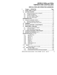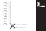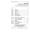
1
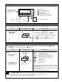
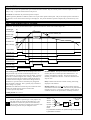
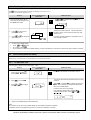
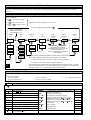
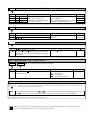
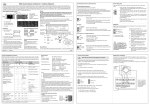
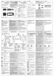
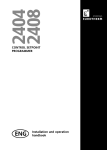
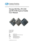
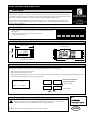
2408i Indicator and Alarm Unit 1 User Guide Thank you for choosing the 2408i panel mounted indicator. It will provide accurate measurement and display of temperature and other process variables. A modular build accepts a wide range of plug-in modules allowing: up to four alarm outputs, two process variable (PV) inputs, direct strain gauge/pressure sensor measurements, custom linearisation, analogue retransmission, remote setpoint (SP) input and digital communications. The indicator is supplied configured in accordance with the order code. The order code and instrument serial number is shown on a label fixed to the top of the case, and this can be checked against the order code given in section 3 of these instructions. 1.1 1. CONTENTS OF PACKAGE A peel-off label set - a convenient position is to fix a label to the top right of the display. A 2.49Ω resistor used as the load resistor for mA inputs Two panel retaining clips 2. 3. , o o C m/s x10 p.s.i p.s.i.x1 0 F cm/s 1x10 bar mmHg K l/h l/min mbar Kg/cm2 kPa mWG T/h mPas gal/min V A % %pH rev/min mV mA %RH pH mile/h Amps 1.2 DIMENSIONS AND INSTALLATION 96 mm (3.78 in) E U R O T H E R M 48 mm (1.89 in) Panel retaining clips 2408I AL1 AL2 AL3 AL4 ACK/ RESET 150mm (4.01in) Latching ears (top & bottom) 1.2.1 To Install the Indicator Please read the safety information in section 4 before proceeding. The indicator is intended to be mounted on a panel within an enclosure such as a control cubicle. 1. 2. 3. 4. Prepare the panel cut-out to the size shown. Insert the indicator through the cut-out. Spring the panel retaining clips into place. Secure the indicator in position by holding it level and pushing both retaining clips forward. Peel off the plastic film protecting the front of the indicator. 92 -0.0 +0.8 X Recommended minimum spacing of indicators 45 mm -0.0 +0.6 38mm (1.5in) 3.62 0.0 +0.03 X 1.77 in -0.0 +0.02 (Not to scale) Panel cut-out 38mm (1.5in) 1.2.2 ! Removing The Indicator From The Sleeve The indicator can be removed from its sleeve by easing the latching ears outwards and pulling it forward out of the sleeve. When plugging the indicator back into its sleeve, ensure that the latching ears click into place to maintain the moisture sealing protection. This indicator meets the European directives on safety and EMC ENG 1.3 ELECTRICAL CONNECTIONS 3D 3C 3B 3A 2D 2C 2B 2A 1D 1C 1B 1A Configurable Plug-in Module Connections Module 3 JF Be sure to check the correct supply voltage before applying power ! Comms Module PDS Input Module Plug-in Communications Module Connections Module 1 Module 2 JE JD JC JB JA HF HE HD HC HB HA Sensor inputs V- Connections common to all indicators V+ VI AC AB AA LC LB LA N Relay Output 1 NC NO Com T/C Pt100 Low voltage supply Neutral Ground Digital input 2 mA Power Supply Connections L Line 24 24 85-264Vac 2.49Ω 20-29Vac/dc Digital input 1 0-10 Vdc Analogue Input 1 1.3.1 Ground Wiring The screw terminals accept wire sizes from 0.5 to 1.5 mm (16 to 22 AWG) and should be tightened to a torque of 0.4Nm (3.5lb in). Hinged terminal covers provide IP20 protection. 1.3.2 Plug-in Module Connections Modules are fitted in positions 1, 2 and 3 in accordance with the ordering code. The tables below show the connections for each module and the possible functions they can perform. Note: On the wiring label the module number precedes the terminal identity letter given in the table below. For example, 1A, 1B, 1C. Module Type Terminal Identity A B C D Typical Module Type Functions Relay; changeover Alarm or Event Dual relay (normally open) DC retransmission Transmitter supply 24V Strain Gauge Transducer supply (see note 1) Alarms or events Terminal Identity A B 2nd Analogue Input Typical C D Functions + - Thermocouple (Analogue Input 2) (module 3 only) + Retrans. of PV - + - + - PRT Cal resistor To power transmitters To power strain gauges. (5V or 10V selectable) + - + - + + Triple contact input Triple digital input Triple digital output - ip1 ip1 op1 ip2 ip2 op2 ip3 ip3 op3 mA (2.49Ω sense resistor) High impedance 0 - 2.0Vdc millivolts 0 - 10Vdc Com Com Notes:1. By default: The transducer supply for input 1 is installed in module position 2 The transducer supply for input 2 is installed in module position 1 2. All module connections are isolated from the process value, earth, incoming supply and connections to other modules. 3. Digital inputs are non-isolated from the process value. Digital inputs are powered by the indicator. Switching voltage and current 24Vdc/20mA. ! 1.3.3 See Section 5 for specifications and maximum safety limits Communications Modules Digital Communications Module PDS Module Terminal identity Terminal identity Module type HB HC HD HE HF RS232 RS485 (2-wire) RS485 (4-wire) Profibus Rx+ Shield RxVP Com Com Com B Rx A (+) Tx+ A Tx B (-) TxDGND Setpoint Input JD JE JF - Signal Common 2 Operation Switch on the indicator. After a 3 second self-test sequence, you will see the display shown below. This is called the ‘HOME’ display. Operator Buttons The default is Process Value (PV). (see 1.7.2 for other HOME display options) AL1 AL2 AL3 Increase parameter value Decrease parameter value AL4 Select parameter Select parameter list heading See following sections for more detail Alarm 1 Alarm 2 Alarm Beacons ACK/ Press to acknowledge alarms RESET Alarm 3 Alarm 4 2.1.1 To View The Display Units If the indicator has been configured for a thermocouple or RTD input, the temperature units can be viewed as follows: Do This 1. This Is The Display You Should See Additional Notes Display Units Press and quickly release the or button. J 0.5 sec / Celsius OR J Fahrenheit OR J' Kelvin The display units are shown for 0.5 second Note: For linear inputs no units are displayed and, in this case: or 2.1.2 Pressing goes directly to the O1 display - see 1.7.2.. Pressing goes directly to the )List - see 1.7.3. Home Display Options When shipped from the factory the HOME display will show the measured temperature or process value. This is the ‘front’ display. If either or is pressed the display changes to the ‘back’ display for a period of two seconds. The back display can show an alternative measurement, such as alarm setpoint or second PV input value. Do This This Is The Display You Should See Example 1. Parameters which can be allocated to the Front and Back displays The HOME display will be blank and only alarm <./.> messages will be flashed Setpoint (for deviation alarms) <0> <5,D0> Remote setpoint (for deviation alarms) ‘back’ display = Alarm setpoint. From the HOME display, or press 2 secs or 2. Press or again to adjust the Alarm Setpoint between hi & lo limits ‘front’ display = Process Value Additional Notes <0;D#O> <0;D)/> <0;> <)D0> <)> <) > Displays the maximum value on input 1 Displays the minimum value on input 1 Process Value Alarm 1 setpoint Linearised input 1 Linearised input 2 Note: If the indicator has been ordered to read the highest (order code HI) or lowest values (order code LO) between input 1 and 2, the display shows only this value. If PV function ordered as FN, the displayed reading will be derived from inputs 1 and 2. L The back display is not selectable in this mode Pressing and together will always return you to the HOME display. OR The display will always return to the HOME display if no button is pressed within 45 seconds. This time is reduced to 10 seconds if an alarm is being displayed. 2.2 ALARMS Alarms are used to alert an operator when a pre-set level has been exceeded. They are normally used to switch an output (see 1.10) – usually a relay – to provide external actions to the process. Soft Alarms are indication only and do not operate an output. Events are generally defined as conditions, which occur as part of the operation of the plant. They do not require operator intervention and, therefore, do not cause an alarm message to be displayed. They can be attached to operate an output (relay) in the same way as an alarm. 2.2.1 Types of Alarm Used In The 2408i This section shows graphically the operation of different types of alarm used in the indicator. The graphs show changes in PV plotted against time. The PV may be derived from input 1, input 2 or the main PV, which is derived from input 1 & 2. Alarm Type PV Full Scale High Process Variable (PV) Deviation High Deviation Band Setpoint (SP) Deviation Low Full Scale Low Rate of Change Output State Full Scale Low Deviation Low On On On On Deviation High Deviation Band On On On Full Scale High Rate of Change On On On Time Rate of change alarms detect if the rate of change in PV, set as units per minute or per second, exceeds the setpoint value. An alarm setpoint set + will detect positive rates of change. An alarm setpoint set - will detect negative rates of change. Therefore, if it is required to measure the rate of change in both directions then two alarms must be configured. Since rate of change alarms are calculated over a period of time a small delay may be apparent before the alarm is indicated. This is generally only noticeable if the PV changes very quickly. Hysteresis is the difference between the point at which the alarm switches ON and the point at which it switches OFF. It is used to prevent relay chatter. Deviation Alarms. The setpoint used for deviation alarms is normally derived as a remote input from another device - for example, a temperature controller. The setpoint can also be internally set within the controller - in this case called the local setpoint value. Delay a settable time between an alarm occurring and it being displayed on the indicator Blocking Alarms only occur after the start up phase when the alarm has first entered a safe state. The alarm is only indicated the next time it is active. It is used, for example, to ignore start up conditions which are not representative of running conditions. Latching Alarms see 1.12.2.xx. 2.2.2 Alarm Relay Output Alarm 1 L Alarms can operate a specific logic or relay output. Any individual alarm can operate an individual relay or any combination of alarms can operate an individual relay. They are either supplied pre-configured in accordance with the ordering code or set up in configuration level. ./5 Alarm 2 Alarm 3 Input fail Sensor break Logic or relay output . OR N! O.: Any combination of alarms can operate the logic or relay output. Typical alarms are shown 2.2.3 Alarm Indication An alarm occurs when the process conditions exceed a pre-set level (setpoint). It will be displayed on the indicator as follows:1. The relevant alarm beacon will begin to flash 2. A four character alarm message will be shown as a double flash in the main display. This message specifies the alarm number (first character) and the type of alarm that has occurred (next three characters). The message is flashed in addition to the ‘front’ displayed value If more than one alarm is present the relevant beacon illuminates and further messages are flashed in the main display. The alarm indication will continue while the alarm condition is present and is not acknowledged. ) ‘front’ display = Process Value (PV) AL1 Alarm Beacon 2.2.4 ‘The message indicates the alarm type eg. <)> = Alarm 1 Full Scale Low See 1.11.1xx for a full list of possible messages Alarm Messages Display Alarm type Input Source Alarm description and function First character BBB BBB BBB BBB Alarm 1 is active Alarm 2 is active Alarm 3 is active Alarm 4 is active Last three characters B) B) B) B# B# B# B)/ B) B) B#O B# B# B: B: B: B56 Full Scale Low Full Scale High Main PV The process value is:- below the low alarm setting PV 1 below the low alarm setting on PV 1 PV 2 below the low alarm setting on PV 2 Main PV above the high alarm setting PV 1 above the high alarm setting on PV 1 PV 2 above the high alarm setting on PV 2 Main PV below the high and low deviation setting on main PV PV 1 below the high and low deviation setting on PV1 PV 2 below the high and low deviation setting on PV2 Main PV above the high and low deviation setting on main PV PV 1 above the high and low deviation setting on PV1 PV 2 above the high and low deviation setting on PV2 Main PV above or below the high and low deviation setting on main PV PV 1 above or below the high and low deviation setting on PV1 PV 2 above or below the high and low deviation setting on PV2 Rate of change (minutes) Main PV changing faster than the rate-of change alarm setting in minutes for main input. B5 Rate of change (seconds) Main PV changing faster than the rate-of change alarm setting in seconds for main input. B56 Rate of change (minutes) Input 1 changing faster than the rate-of change alarm setting in minutes for input 1. B5 Rate of change (seconds) Input 1 changing faster than the rate-of change alarm setting in seconds for input 1. B56 Rate of change (minutes) Input 2 changing faster than the rate-of change alarm setting in minutes for input 2. B5 Rate of change (seconds) Input 2 is changing faster than the rate-of change alarm setting in seconds for input 2. B)0 B#0 5 Setpoint Low Main PV Setpoint High Main PV L Deviation Low Deviation High Deviation Band The setpoint is:- below the low alarm setting above the high alarm setting Sensor Break alarm (open circuit input 1 or derived PV) If the process value flashes but no other alarm message is displayed, this indicates that the input which is being used as the PV is out of range. 2.2.5 Diagnostic Alarms In addition to the process alarms given in the previous column the following diagnostic alarms may also appear. These warn that a fault exists in either the indicator or the connected devices. Alarm What it means D5 Electrically Erasable Memory Error: The value of an operator or configuration parameter has been corrupted. This fault will automatically select configuration level. Check all configuration parameters before returning to operator level. Once in operator level, check all operator parameters before resuming normal operation. If the fault persists or occurs frequently, return the unit for repair. What to do about it )))) #### 55 55 55 55 Out of range low reading Check the value of the input Out of range high reading Check the value of the input Error 1: ROM self-test fail Return the indicator for repair Error 2: RAM self-test fail Return the indicator for repair Error 3: Watchdog fail Return the indicator for repair Error 4: Keyboard failure. Stuck button, or a button was pressed during power up. Switch the power off and then on without touching any of the indicator buttons. If the error continues return the unit for repair. 55 #=D5 Error 5: Input circuit failure Return the unit for repair Hardware error Indication that a module is of the wrong type, missing faulty, or a new module has been fitted. Check that the correct modules are fitted. Go to configuration mode and set up the required parameter(s). Refer to the Engineering Handbook, Part Number Haxx for further information. 0=5D 5,6D Power failure: The line voltage is too low Check that the supply is within rated limits Remote input fail Connect an input device (eg. transducer, thermocouple, mA source) to input 2 2.2.6 To Acknowledge An Alarm An alarm can be acknowledged in two ways:1. Press the ACK/RESET button. (If this does not work it may have been disabled when the indicator was configured). 2. Press and together. The action, which now takes place, will depend on the type of latching, which has been configured Non Latched Alarms If the indicator has been configured for non-latching alarms the following action occurs:Alarm condition present when the alarm is acknowledged, will be indicated by a single flash of the alarm message and the beacon will continuously illuminate. This state will continue for as long as the alarm condition remains. When the alarm condition disappears the indication will also disappear. If a relay has been attached to the alarm output, it will operate when the alarm condition occurs and remain in the operated condition until the alarm is acknowledged AND it is no longer present. If the alarm condition disappears before it is acknowledged the alarm indication disappears as soon as the condition disappears. Latched Alarms The indicator may have been configured for Automatic or Manual reset. The action which occurs when the acknowledge button is pressed is described below:Automatic. The alarm continues to be active until both the alarm condition is removed AND the alarm is acknowledged. The acknowledgement can occur BEFORE the alarm condition is removed. Manual The alarm continues to be active until both the alarm condition is removed AND the alarm is acknowledged. The acknowledgement can only occur AFTER the alarm condition is removed. 2.2.7 Alarm Inhibit If a digital input has been configured for alarm inhibit, then all process alarm indication will be prevented for as long as the input is ON. When the input is turned to OFF any alarms which are active will be displayed. If a delay has been set on the alarm, the delay period will start from the time when the input is turned OFF. If the alarm has been configured as latching the latching action is also inh ibited whenever the input is ON. 2.2.8 To Change The Alarm Setpoints (trip levels) Parameters are grouped in ‘lists’ according to their function. Each list has a heading. button steps through the parameter list headings (see section 2.4.1.) The The first list is the alarm setpoints list ) Do This This Is The Display You Should See 1. From any display press as many times as necessary to show the ‘Alarm List’ header 2. Press to show the first parameter in the list or Press alarm setpoint 3. to change the ) D BBB Additional Notes L L If or are pressed the word ‘)O6is displayed for 2 secs )O6 ) There are four alarm setpoints. The first character is the alarm number, the next three the alarm type (see section 2.2.4.) If an alarm has been disabled in configuration level, it will not appear in this list. or 4. To return to the HOME display:• Press • • or continue to press or the indicator will return to the HOME display if no button is pressed for 45 seconds (10 seconds if an alarm condition is present). 2.3 and together AUTO-TARE (DISPLAY ZERO) The auto-tare function is used, for example, when it is required to weigh the contents of a container but not the container itself. Alternatively, it can be used to set a fixed offset on an initial measured value. 2.3.1 To Use Auto Tare Place the empty container on the weigh-bridge. Then:Do This 1. From any display press as many times as necessary to show the ‘) List’ header 2. Press 3. Press from This Is The Display You Should See ) to scroll to 65 or to /. and change 65 /. Additional Notes L L Use ) if the load cell is connected to input 2 The indicator automatically calibrates itself to the empty container. When 65 is turned to /., the display will change to 9@. When calibration is complete the display will return to the HOME display. It will then return to the main display. If the calibration fails the alarm message 65D (transducer fail) will flash. Press acknowledge. 9@ 4. and to Return to the HOME display as described above Note:The indicator will not return to the HOME display until the calibration procedure completes. If calibration does not complete after a period of 5 minutes, then calibration is aborted. The full list of parameters available in these lists is shown in the parameter tables is shown in the following section. 2.4 TO ACCESS AND CHANGE PARAMETER VALUES Parameters are settings within the indicator, which determine how it will operate. Examples are Alarm Setpoints and Tare Values already mentioned. They are organised into different lists. Each list has a named heading which describes a particular subject, for example ‘Alarms’ ()). 2.4.1 Operator Level Navigation Diagram (factory default) To find a parameter:Press to select the list heading Press to select the parameter Press or Examples are shown in sections 2.2 7. and 2.3.1. to change its value To return to HOME page keep pressing Note:- The first press displays the instrument units described in 2.1.1. HOME List Alarm List Setpoint List Input List Input 1 calibration List ) 0 O0 ) BBB 1) O.6D6 BBB 1# X2 Input 2 calibration List Access List ) (2) (1) 1D (1) 1D (1) O BBB Only present if ordered with configuration options SG or MP, see ordering code section 3. See also the Engineering Handbook further details. / !/6/ (1) BBB • This list shows the parameters available in operator level in a new instrument. • Blocks shown shaded are dependant upon the order code as follows:- (1) These parameters are only shown if the alarm has been configured L 2.5 (2) CAL2 list is only shown if Input 2 has been configured • The above list can be customised to suit the requirements of a particular process. Complete lists or individual parameters in a list can be added during commissioning. The procedure is described in section 3.4 ‘To Hide. Reveal and Promote Parameters’. PARAMETER TABLES The parameter tables provide a full list of parameters, an explanation of their use and where to find them. Use these lists to adjust:• The alarm setpoints • The alarm setpoint limits • • The User calibration The input filter time constant 2.5.1 HOME Home List 0D HOME display front Selectable options The HOME display will be blank and only alarm <./.> messages will be flashed Setpoint (for deviation alarms) <0> <0;D)/> 0D DO Customer defined identity number associated with a physical position The communications address HOME List <5,D0> <0;D#O> HOME display back • <0;> <)D0> <)> <) > to Default 0; Remote setpoint (for deviation alarms) Displays the maximum value on input 1. This parameter is the same as <)!D#> in <O./> list Displays the minimum value on input 1. This parameter is the same as <)!D)> in <O./> list Process Value Alarm 1 setpoint Linearised input 1 Linearised input 2 ) ) BBB BBB BBB BBB 2.5.2 Alarm list Comments Adjustable Range Alarm 1 setpoint The last three letters indicate the Between low and high setpoint limits which Alarm 2 setpoint Alarm type. See section 2.2.4. As set in the 0 list. Alarm 3 setpoint If the alarm is disabled the parameter Rate of change alarms are direction sensitive Alarm 4 setpoint will not appear in this list from-9999 to +99999 units/sec or min 0 1 0) 0# 2.5.3 O.6D6 Default Setpoint List Setpoint list Adjustable Range Default Setpoint low limit – PV alarms Input range min and max (combination of As per Setpoint high limit – PV alarms inputs 1 & 2 O0 O1 Alarm List 2.5.4 order code Input List Setpoint list Adjustable Range Input filter integrating time constant to D seconds Default D Set to a value which reduces the effect of any input noise to an acceptable level. The higher the value the more sluggish the response 2.5.5 User Calibration Lists – Inputs 1 and 2 )D or )D )DB 65 () only appears if input 2 has been configured) User calibration 1 or 2 list Adjustable Range Default Performs automatic ‘Tare’ correction = Off /.= start correction 9A= inputting value /.= finished inputting value See also section 2.3. 2.5.6 / Access List The Access List provides password protected access to further levels of operation as listed below. See section 3 of the Engineering Handbook, part No. HA027240, for further details. A code number can be entered using the or buttons. If an incorrect code number is entered the display will revert to </>. If no button is pressed within 45 seconds the indicator will automatically return to the HOME display. For information on further levels of access, see the following sections. L Details of configuration are not included in this operation guide. A full engineering reference and configuration manual is available from the Eurotherm web site or as a booklet, part number HAxx. 3 Ordering Code Model number 2408i Function Display colour Module 1 Module 2 Module 3 Relay Output 1 Comms Module PDS Module Manual AL AL AP Function Indicator/Alarm unit Profibus Indicator GN RD Display colour Green display Red display VH VL Supply voltage 85-264Vac 20-29Vac/dc Note 1: By default, alarm 1 will be assigned to relay output 1 and alarms 2, 3 and 4 will be assigned to Modules 1, 2 and 3 respectively. Note 2: The allocation of alarms to the dual relay outputs must be performed in configuration by the customer. Note 3: Triple contact or logic inputs can be configured, by the user, for any of the functions listed under Digital Inputs 1 and 2. Note 4: The triple logic output can configured as alarm outputs or as telemetry outputs via digital communications. Sensor Input Supply voltage Modules 1, 2 and 3 XX Module not fitted Alarm Relay output (change-over) R4 Module fitted unconfigured OR Select alarm configuration from table A. DC retransmission D6 Module fitted unconfigured First character VProcess Value retransmission SSetpoint retransmisssion ZError retransmission Second character -1 0-20mA -2 4-20mA -3 0-5Vdc -4 1-5Vdc -5 0-10Vdc Dual relay (Note 2) RR Module fitted unconfigured Triple contact input (Note 3) TK Module fitted unconfigured Triple logic input (Note 3) TL Module fitted unconfigured Triple logic output (Note 4) TP Module fitted unconfigured 20mA Transmitter supply MS 24Vdc, 20mA supply Strain Gauge Transducer supply (modules 1 & 2 only) (note 5) G3 5V transducer supply G5 10v transducer supply 2nd analogue input (module 3 only) D5 Module fitted unconfigured For configuration, see PV Function field SOFTWARE CONFIGURATION Setpoint Setpoint Display Digital min max Units input 1 Note 6 Note 6 Table A: Alarm relay configuration (See note 1) Non-latched alarms FH High alarm FL Low alarm DB Deviation band alarm DL Deviation low alarm DH Deviation high alarm RA Rate-of -change alarm Latched alarms HA High alarm LA Low alarm BD Deviation band alarm WD Deviation low alarm 10 AD Deviation high alarm RT Rate-of -change alarm NW New alarm PDS module Module not fitted Module fitted unconfigured Remote setpoint input XX M6 RS XXX ENG FRA GER NED SPA SWE ITA Note 5: By default, the transducer supply for input 1 will be installed in module position 2 and the transducer supply for input 2 in module position 1. Manual None English French German Dutch Spanish Swedish Italian Configuration of 2nd analogue input requires D5 in module 3 2 DC PV Function 2nd Input 2nd Input ConfiguratInput Display Min Display Max ion option Note 7 Note 8 Note 8 Setpoint min & max °C Thermocouples J Type J K Type K T Type T L Type L N Type N R Type R S Type S B Type B P Platinell II Z Pt100 Process inputs (Scaled to setpoints max & min) F -100 to +100mV Y 0 to 20mA (note 2) A 4 to 20mA (note 2) W 0 to 5Vdc G 1 to 5Vdc V 0 to 10Vdc Factory downloaded input C Type C -W5%Re/W26%Re “Table Reference (default downloaded input) Number” 6 D Type D - W3%Re/W25%Re “T035” E E thermocouple “T012” 1 Ni/Ni18%Mo “T033” 2 Pt20%Rh/Pt40%Rh “T025” 3 W/W26%Re (Engelhard) “T09” 4 W/W26%Re (Hoskins) “T029” 5 W5%Re/W26%Re (Engelhard) “T011” 6 W5%Re/W26%Re “T038” (Bucose) 7 Pt10%Rh/Pt40%/Rh “T023” 8 Exergen K80 I.R. Pyrometer “5” Comms module XX Module not fitted RS232 Module A2 Module fitted unconfigured AM Modbus protocol AE EI-Bisynch protocol RS485 (2-wire) Module Y2 Module fitted unconfigured YM Modbus protocol YE EI-Bisynch protocol RS485 (4-wire) (= RS422) Module F2 Module fitted unconfigured FM Modbus protocol FE EI-Bisynch protocol Profibus Module PB High speed RS485 nd Digital input 2 Sensor input & 2nd DC input Relay Output 1 XX Not fitted RF Fitted unconfigured OR Select alarm configuration from table A Min Max -210 1200 -200 1372 -200 400 -200 900 -250 1300 -50 1768 -50 1768 0 1820 0 1369 -200 850 Range Min -9999 -9999 -9999 -9999 -9999 -9999 °F Min -340 -325 -325 -325 -418 -58 -58 32 32 -325 Max 2192 2500 750 1650 2370 3200 3200 3308 2496 1562 Range Max 99999 99999 99999 99999 99999 99999 C o F o XX LO HI FN RS XX AC KL SR PV M5 0 to 2319 32 to 4200 J1 0 to 2399 -270 to 999 0 to 1399 0 to 1870 0 to 2000 0 to 2010 10 to 2300 0 to 2000 32 to 4350 -450 to 1830 32 to 2550 32 to 3398 32 to 3632 32 to 3650 50 to 4172 32 to 3632 J2 200 to 1800 -45 to 650 392 to 3272 -49 to 1202 J3 J4 XX SG CL C Display Units K F X p K Blank PV function Input 1 displayed PV = the lowest of i/p 1 and 2 PV = the highest of i/p 1 and 2 PV derived from i/p 1 and 2 Remote setpoint Digital inputs 1 & 2 Disabled Alarm acknowledge Keylock Remote setpoint select Select process value input 2 CTX mode 5 (digital input 2 only). For use with PDTCX ‘smart’ current transformer. Initiate tare correction on strain gauge input 1 Initiate tare correction on strain gauge input 2 Initiate automatic calibration of strain gauge input 1 Initiate automatic calibration of strain gauge input 2 Configuration Option Standard Load cell/strain gauge pressure transducer Note 6: Setpoint min and max: Include the decimal points required in the displayed value; up to one for temperature, up to two for process inputs. Note 7: Select the code required from the Sensor Input table nd Note 8: These two fields are used to scale the 2 DC input if it is a linear process input, otherwise it should be left blank. Note 9: For mA inputs, a 1% 2.49Ω current sense resistor is supplied. If greater accuracy is required, a 0.1% resistor can be ordered as Part number SUB2K/249R.1 4 Safety and EMC Information Enclosure of live parts Safety The indicator must be installed in an enclosure to prevent hands or metal tools touching parts that may be electrically live. This indicator complies with the European Low Voltage Directive 73/23/EEC, amended by 93/68/EEC, by the application of the safety standard EN 61010. Caution: Live sensors The alarm acknowledge/keylock input is electrically connected to the sensor input (e.g. thermocouple). In some installations the temperature sensor may become live. The indicator is designed to operate under these conditions, but you must ensure that this will not damage other equipment connected to the logic input/output and that service personnel do not touch this connection while it is live. With a live sensor, all cables, connectors and switches for connecting the sensor and nonisolated inputs and outputs must be mains rated. ! Electromagnetic compatibility This indicator conforms to the essential protection requirements of the EMC Directive 89/336/EEC, amended by 93/68/EEC, by the application of a Technical Construction File. This indicator satisfies the general requirements of the industrial environment defined in EN 50081-2 and EN 50082-2. General The information contained in these instructions is subject to change without notice. While every effort has been made to ensure the accuracy of the information, your supplier shall not be held liable for errors contained herein. Wiring Wire the indicator in accordance with the wiring data given in these instructions. Take particular care not to connect AC supplies to the low voltage sensor input or logic outputs. Only use copper conductors for connections, (except thermocouple). Ensure that the installation complies with local wiring regulations, and observe maximum voltage safety limits. ! Unpacking and storage The packaging should contain the indicator, two panel retaining clips, a 2.49Ω current sense resistor and this instruction leaflet. If the packaging or the indicator is damaged, do not install the product but contact your supplier. Power Isolation ! This indicator has no user serviceable parts. Contact your supplier for repair. Caution: Charged capacitors ! Before removing the indicator from its sleeve, switch off the supply and wait two minutes to allow capacitors to discharge. Failure to observe this precaution may damage the indicator or cause mild electric shock. Voltage rating ! When the indicator is removed from its sleeve, it is vulnerable to damage by electrostatic. To avoid this, observe anti-static handling precautions. Conductive pollution Cleaning Do not use water or water based products to clean labels or they will become illegible. Isopropyl alcohol may be used to clean labels. A mild soap solution may be used to clean other exterior surfaces of the product. ! Safety Symbols The following safety symbols are used on the controller and in this manual: ! L Caution, Important safety information The maximum continuous voltage applied between any connection and ground must not exceed 264Vac. For the above reason the indicator should not be wired to a three-phase supply with an unearthed star connection. Under fault conditions such a supply could rise above 264Vac with respect to ground and the product would not be safe. Precautions Against Electrostatic Discharge Damage ! The installation must include a power isolating switch or circuit breaker that disconnects all current carrying conductors. The device should be mounted in close proximity to the indicator, within easy reach of the operator and marked as the disconnecting device for the indicator. Functional earth (ground) terminal Useful information or hint Electrically conductive pollution must be excluded from the cabinet in which the indicator is mounted. For example, carbon dust is a form of electrically conductive pollution. Where condensation is likely, for example at low temperatures, include a thermostatically controlled heater in the cabinet. Installation requirements for EMC • • For general guidance refer to EMC Installation Guide, HA025464. It may be necessary to fit a filter across the relay output to suppress conducted emissions. The filter requirements will depend on the type of load. For typical applications we recommend Schaffner FN321 or FN612. Personnel Routing of wires Installation must be carried out by qualified personnel. To minimise the pick-up of electrical noise, the sensor input wiring should be routed away from high-current power cables. Where it is impractical to do this, use shielded cables with the shield grounded at both ends. 5 Technical Specification Main process value input and second DC input DC retransmission Low level range High level range Sample rate Resolution Range Resolution Retransmission values Linearity Calibration accuracy User calibration Input filtering Thermocouple types Cold junction compensation 3-wire Pt100 input. Bulb current: Maximum lead resistance nd 2 analogue input functions Input impedance, mV inputs Input impedance, Volt inputs -100 to +100mV 0-20mA or 0-10Vdc 9Hz <2µV for low level inputs <2mV for high level inputs o Better than 0.2 C o +0.2% of reading, or +1 C or +1LSD, whichever is the greater Low and high offsets can be applied OFF to 999.9 seconds Refer to ordering code sensor input table In automatic mode, >30:1 rejection of ambient temperature change. 0.3mA Up to 22Ω in each lead without error nd 2 process value, remote setpoint, select min, select max, derived value >10MΩ >69KΩ Transmitter supply Rating Bridge voltage Bridge resistance Internal shunt resistor Number of alarms Alarm types Contact closure or open collector inputs Alarm delay Switching voltage/current: 24Vdc/20mA nominal Off state resistance <100Ω On state resistance >28KΩ Isolated. Specification as dig. inputs 1 & 2 Module types Protocols Off state: <5Vdc On state: 10.8 to 30Vdc @ 2.5mA PDS Functions Display colour Number of digits Supply Digital input functions As per digital inputs 1 & 2 in the ordering code Digital outputs 2A, 264Vac resistive 8mA, 12Vdc per channel as per the ordering code Power consumption Operating ambient Storage temperature Panel sealing Dimensions Weight EMC Standards: Safety standards 6 International Sales & Service EUROTHERM CONTROLS LTD Faraday Close, Durrington, Worthing, West Sussex BN13 3PL Telephone Sales: (01903) 695888 Technical: (01903) 695777 Service: (01903) 695444 Fax (01903) 695666 Countries not listed - enquiries/orders to: Eurotherm Controls Limited, Export Dept,. Faraday Close, Durrington, Worthing, West Sussex, BN13 3PL Telephone (01903) 268500 Fax (01903) 265982 AUSTRALIA Eurotherm Pty. Ltd. Telephone Sydney (+61 2) 9477 7022 Fax (+61 2) 477 7756 AUSTRIA Eurotherm GmbH Telephone Vienna (+43 1) 798 7601 Fax (+43 1) 798 7605 Telex 047 1132000 EIAUT A BELGIUM Eurotherm B.V. Telephone Antwerp (+32 3) 322 3870 Fax (+32 3) 321 7363 DENMARK Eurotherm A/S RS232, 2-wire RS485 and 4-wireRS485 Modbus or EI-Bisynch (ASCII) Remote setpoint input from master controller General Externally powered inputs Relay rating Triple logic output Digital output functions Four High, low, deviation high, deviation low, deviation band, rate of change in units/sec, rate of change in units/min, new alarm status. Sensor break alarm Latching or non-latching. Blocking Energised or de-energised in alarm OFF to 999.9 secs Communications Note: These are powered by the controller Triple logic inputs Software selectable, 5 or 10Vdc 300Ω to 10KΩ 30.1KΩ at0.25%, used for calibration of 350Ω bridge Alarms Alarm modes Triple contact closure inputs 20mA, 24Vdc Strain gauge bridge supply Digital inputs Digital inputs 1 & 2 (Non isolated from PV) Scaleable between 0-20mA and 0-10Vdc 1 part in 10,000 Process value, setpoint or error from Telephone Copenhagen (+45 31) 871622 Fax (+45 31) 872124 FRANCE Eurotherm Automation SA Telephone Lyon (+33 478) 664500 Fax (+33 478) 352490 GERMANY Eurotherm Regler GmbH Telephone Limburg (+49 6431) 2980 Fax (+49 6431) 298119 Also regional offices HONG KONG Eurotherm Limited Telephone Hong Kong (+852) 2873 3826 Fax (+852) 2870 0148 Telex 0802 69257 EIFEL HX INDIA Eurotherm India Limited Telephone Chennai (+9144) 4961129 Fax (+9144) 4961831 IRELAND Eurotherm Ireland Limited Telephone Naas (+353 45) 879937 Fax (+353 45) 875123 Atmospheres ITALY Eurotherm SpA Telephone Como (+39 31) 975111 Fax (+39 31) 977512 Telex 380893 EUROTH I JAPAN Eurotherm Japan Limited Telephone Tokyo (+81 3) 33702951 Fax (+81 3) 33702960 KOREA Eurotherm Korea Limited Telephone Seoul (+82 2) 5438507 Fax (+82 2) 545 9758 Telex EIKOR K23105 NETHERLANDS Eurotherm B.V. Telephone Alphen a/d Ryn (+31 172) 411752 Fax (+31 172) 417260 Red or green options Five with up to three decimal places 100 to 240Vac -15%+10% OR 24 Vdc or ac 15%+20% 15W max o 0 to 55 C and 5 to 95% RH non-condensing o -10 to +70 C IP65 96W x 48H x 150D 400g max EN50081-2 & EN50082-2 generic standards for industrial environments Meets EN 61010, Installation category II, pollution degree 2. Not suitable for use above 2000m or in explosive or corrosive atmospheres NORWAY Eurotherm A/S Telephone Oslo (+47 66) 803330 Fax (+47 66) 803331 SPAIN Eurotherm España SA Telephone (+34 91) 6616001 Fax (+34 91) 6619093 SWEDEN Eurotherm AB Telephone Malmo (+46 40) 384500 Fax (+46 40) 384545 SWITZERLAND Eurotherm Produkte (Schweiz) AG Telephone Zurich (+41 55) 4154400 Fax (+41 55) 4154415 U.S.A Eurotherm Controls Inc. Telephone Reston (+1 703) 787 3405 Fax (+1 703) 787 3436 NEW ZEALAND Eurotherm Limited Telephone Auckland (+64 9) 2635900 Fax: (+64 9) 2635901 Part Number HA027239 Issue 1.0