1
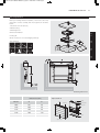
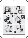
24197 iVector Installation Guide V2_Layout 1 28/11/2011 14:49 Page 2
Installation, Operating, Maintenance
and After Sales Manual.
iVECTOR Heater/Cooler
Models: iV080, iV100, iV120, iV140, iV160
heatingthroughinnovation.
01.10.2011 ISSUE 1
Product Serial Number:
Please leave this manual with the end user.
Part Number: 1370067
Issue 1
24197 iVector Installation Guide V2_Layout 1 28/11/2011 14:49 Page 3
Contents
1.0
Introduction
03
2.0
Warnings & Safety Measures
03
3.0
Heating System Design
03
4.0
Unit Selection/Sizing
04
5.0
Location
04
6.0
Preparation
05
7.0
Fixing
06
8.0
Water Connection
07
9.0
Electrical Connection
08
10.0
Commissioning Procedure
11
11.0
Technical Data
12
12.0
Control System Set-up and Operating Instruction
13
12.1 Unit Operation
13
12.2 Operating Modes
15
12.3 Installer’s Set-up Parameters
16
12.4 Building Management System Input Set-up
16
12.5 Program Mode
17
13.0
Troubleshooting
18
14.0
Maintenance
19
15.0
Spare Parts & Accessories
19
24197 iVector Installation Guide V2_Layout 1 28/11/2011 14:49 Page 4
iVECTOR Heater/Cooler
03
A range of accessories are available for this product including
control valves and condensate pumps for cooling installations.
The control system provides thermostatic room temperature and
fan speed control, and allows operation on a stand-alone basis,
or by integration into building management systems.
This manual should be read carefully prior to installation and retained for future reference.
2.0 Warnings & Safety Measures
This unit MUST NOT be installed in a bathroom or other high humidity area.
This appliance must be earthed.
DO NOT cover or obstruct the air inlet or outlet grille.
Disconnect from the power supply before carrying out any maintenance work.
l Please carefully follow the instructions and guidelines
contained in this manual during installation. Always perform
each step in sequence.
l Inspect this product for concealed shipping damage prior to
installation. If items are damaged or missing please contact
your supplier.
l This fan convector must be installed by qualified engineers.
l This fan convector must not be installed immediately below a
socket outlet.
l Do not install this fan convector in areas where excessive
dust exists.
l This appliance is not intended for use by persons (including
children) with reduced physical, sensory or mental
capabilities, or lack of experience or knowledge, unless they
have been given supervision or instruction concerning us of
the appliance by a person responsible for their safety.
Children should be supervised to ensure that they do not play
with the appliance.
l The manufacturer accepts no liability for damage or injury
caused by failure to adhere strictly to the safety precautions
and instructions contained in this manual, or by negligence
during the installation of the product and any accessories
described in this manual.
l For the correct installation of this unit it is essential that
fixing is carried out in such a way that it is suitable for
intended use and predictable misuse. A number of elements
need to be taken into consideration including the fixing
method used to secure it to the wall, the type and condition
of the wall itself, and any additional potential forces or
weights that may happen to be applied to the unit, prior to
finalising installation.
l Please leave this manual with the end user.
3.0 Heating System Design
This heater/cooler should only be used on closed circulation, two pipe, pump assisited central heating
systems or heating and cooling systems.
This heater/cooler fan convector is designed for wall mounted
installation.
For optimum fan convector performance the system must be
capable of providing sufficient flow of water through the heat
exchanger at the correct temperature. This means that:
1. The unit is not suitable for use on microbore pipework.
2. This unit is not suitable for 1 pipe systems.
3. Optimum performance will require effective balancing of the
whole system. Each emitter on the circuit should be checked
and valves adjusted so that the required water flow rate
through each unit is achieved.
4. Where the unit is fitted on to a system with other emitters a
separate circuit for the fan convector should be considered
in order to provide sufficient flow through the unit.
5. The system water must be above 32°C for heating mode and
below 15°C in cooling mode.
6. This unit must not be used to replace a radiator in an existing
heating system unless an adequate flow of water through the
unit can be guaranteed.
2.0
The unit is fitted with a washable air filter that can be easily
removed for cleaning.
3.0
This heater/cooler fan convector is designed for use on
central heating systems or heating and cooling systems in
homes and commercial environments. Models are available
with 2 connections.
1.0
1.0 Introduction
24197 iVector Installation Guide V2_Layout 1 28/11/2011 14:49 Page 5
04
iVECTOR Heater/Cooler
3.0 Heating System Design
(continued...)
Model
Minimum Pipe Size (mm)
(2 pipe units)
iV080
15 *
iV100
15 **
iV120
22
iV140
22
iV160
22
* 8m max recommended pipe run. Increase pipe diameter if longer run is needed.
** 4m max recommended pipe run. Increase pipe diameter if longer run is needed.
Note: A pressure independent balancing and control valve is
available for this product as an accessory. This valve can simplify
system design by eliminating the possible need for larger
balancing valves elsewhere in the system, and will maintain the
flow in the unit to the required levels. See accessories section
for more details.
No microbore pipework
4.0 Unit Selection/Sizing
Heat output performance data is given in the technical data
section of this manual (see page 12). Outputs are shown for the
three fan speeds, however, it is important to size the unit to
match the calculated heat loss requirements of the room with
the unit operating on the normal fan speed. The higher fan
speeds are used in Comfort mode when the room temperature
is significantly lower than the preset temperature.
Note: It is also possible to electronically remove the highest fan
speed from the functionality of this unit via the control system
(see page 16). This may be advantageous on low temperature
systems to prevent cool air being blown into the room on the
highest setting.
When establishing the temperature difference, ie mean water to
room temperature difference, allowance should be made for the
temperature drop in the system. It is the water temperature at
the unit that dictates the output.
5.0 Location
This unit may be fitted to any convenient wall at a height from
the floor level that suits the application, providing an unimpeded
flow of air into the area to be heated/cooled.
Mount on a
flat wall with
sufficient side
clearance.
For cooling applications, the need for disposal of condensate
may influence the position of the unit.
NO mounting
on uneven wall
surfaces
NO mounting
on stud walling
24197 iVector Installation Guide V2_Layout 1 28/11/2011 14:49 Page 6
iVECTOR Heater/Cooler
05
6.0 Preparation
Before proceeding with the installation, remove the carton lid,
unpack the contents carefully and check against the checklist
below:
1. Heater Cooler unit (chassis)
2. Outer Casing
3. Warranty Card
1
3.0
4. Instruction Manual
5. Fixing kit
Check contents for concealed shipping damage.
2
rran
Wa
ty
3
4.0
Tools required:
4
nu a
l
5.0
Ma
6.0
5
Mounting dimensions
Dimensions (mm)
Exploded View
Chassis
Model
A
B
Grill
Grill hinge
iV080
800
503
iV100
1000
703
iV120
1200
903
iV140
1400
1103
iV160
1600
1303
Control panel
Side cover
Filter
Outer casing
24197 iVector Installation Guide V2_Layout 1 28/11/2011 14:49 Page 7
06
iVECTOR Heater/Cooler
7.0 Fixing
1.
2.
B
236
236
3.
4.
5.
6.
NOTE: Do not replace outer cover until connection to system and connection to electrical supply
has been completed.
24197 iVector Installation Guide V2_Layout 1 28/11/2011 14:49 Page 8
iVECTOR Heater/Cooler
07
8.0 Water Connection
Connect the unit to the flow and return pipes. Pipe-work can be
routed from the floor or through the wall at the back of the unit.
(See options below). Connections are G3/4".
needed and can be removed by unscrewing the two bracket
fixing screws. Removal of this component will aid pipe-work
fitting when the pipes are routed up from the floor.
Connection directly onto the heat exchanger should be made
using straight connectors so that the pipe-work can more easily
be routed inside the unit.
For applications involving cooling, the pipe-work must be routed
to avoid the condensate collector. Connection to the heat
exchanger should be made using straight connectors so that the
pipe-work can more easily be routed past the condensate
collector.
For heating only applications the condensate collector mounted
on the chassis below the heat exchanger connections is not
Before making the pipe-work connections refer to section 3.0 for advice on System Design.
Pipe Routing Options
2-pipe connection
7.0
83 -108* MAX
8.0
* Dimension from chassis side to pipe centre.
Note 1: The flow pipe should be connected to the bottom
connection of the heat exchanger.
Note 2: Isolating valves are not supplied with this unit, but
should be fitted in case of future service requirements.
The type and size of valves and their location should be suitable
for the application. Valves should be selected in accordance with
system temperature and pressure requirements whilst taking into
account pressure drop characteristics.
Note 3: External pipe-work carrying chilled water must be
insulated. Use a suitable sealant as necessary to ensure that
condensate does not spill or leak. Once connection to the
system flow and return pipes is made, any exposed internal
15mm pipe-work and isolating valves must also be insulated.
Dimensions 2-pipe
60
24197 iVector Installation Guide V2_Layout 1 28/11/2011 14:49 Page 9
08
iVECTOR Heater/Cooler
8.0 Water Connection
(continued...)
How to bleed/vent
Condensate drain connection
Spiggot size
15mm O/D
Connecting tube
>15mm I/D
Ensure all water fittings are secure before filling the heating
system.
A drain tray is fitted for condensate collection within the unit.
This should be connected to a 15mm drain pipe.
Fill the heating system, open the valves fully and check pipe
connections for leaks and vent the heat exchanger.
Alternatively a condensate disposal pump is available as an
accessory, e.g. for use on internal walls (see Accessories page).
Installations with chilled water will require provision for
condensate disposal in accordance with any local regulations.
9.0 Electrical Connection
WARNING: This appliance must be earthed. The electrical installation must comply with local or national
wiring regulations.
l The electrical installation of this appliance should be carried
out by a qualified electrician in accordance with current
regulations.
l Connect the live and neutral wires to the power board
terminal connections, and the earth wire to the chassis earth
terminal.
l This unit is supplied with factory fitted test leads. Remove
these and discard.
For Building Management System
l A fused electrical spur with a maximum 3A fuse and a switch
having 3mm separation on all poles must be provided in an
easily accessible position adjacent to the unit.
l Electrical cable entry to the unit should be made through the
underside of the unit, into the control box on the right hand
side using the cable gland provided. The supply cord must be
0.75mm² only.
l Connect wires from BMS and valves as necessary, using the
same cable routing into the control box, and with the second
cable gland supplied.
24197 iVector Installation Guide V2_Layout 1 28/11/2011 14:49 Page 10
iVECTOR Heater/Cooler
9.0 Electrical Connection
09
(continued...)
1. Remove x 2 screws to access control panel
2. Remove control panel cover
Refer to wiring diagrams on pages 10 & 11.
3. Routing cable
After making the electrical connections replace the side cover
to the control box.
BMS Connection
8.0
Control Valve
Connection
Live
Neutral
9.0
Earth
Cable Entry
Points
24197 iVector Installation Guide V2_Layout 1 28/11/2011 14:49 Page 11
10
iVECTOR Heater/Cooler
9.0 Electrical Connection
(continued...)
2-pipe 0 valve
CONTROL
BOARD
POWER
BOARD
R
W
Y
M+
T+
L
N
Supply 230V
50Hz
TM-
BR
Hi
R
WATER SENSOR
2-PIPE
Med
W
Lo
AIR
SENSOR
FAN
Y
BL
TRANSFORMER
2-pipe 1 valve
Supply 230V 50Hz
24V 50Hz
24V DC
CONTROL
BOARD
POWER
BOARD
+
-
R
W
Y
M+
T+
Supply 230V
50Hz
L
N
TM-
BR
Hi
R
WATER SENSOR
2-PIPE
Med
W
Lo
Y
BL
TRANSFORMER
FAN
AIR
SENSOR
24197 iVector Installation Guide V2_Layout 1 28/11/2011 14:49 Page 12
iVECTOR Heater/Cooler
9.0 Electrical Connection
11
(continued...)
2-pipe 1 valve + BMS
24V AC
BUILDING
MANAGEMENT
SYSTEM
Supply 230V 50Hz
24V 50Hz
24V DC
COM
FAST
SLOW
HEAT
COOL
+
-
CONTROL
BOARD
POWER
BOARD
R
W
Y
M+
T+
Supply 230V
50Hz
L
N
TM-
BR
Hi
R
WATER SENSOR
2-PIPE
Med
W
Lo
Y
AIR
SENSOR
FAN
BL
TRANSFORMER
10.0
9.0
10.0 Commissioning Procedure
1
2
1. l Fill and vent the system.
l Open all valves fully and vent air from the heat exchanger.
l Check for leaks at pipe connections.
2. l Refit the outer casing and secure with the 2 screws.
l Switch on the electrical supply.
l Check the operation of the unit by following the operating
instructions.
3. l Set up the installation parameters on the controls system
as necessary.
l When installation and commissioning are complete, hand
over the instruction manual to the end user.
3
24197 iVector Installation Guide V2_Layout 1 28/11/2011 14:49 Page 13
12
iVECTOR Heater/Cooler
11.0 Technical Data
Dimensions
Weight, Water Content and Motor Power
Model
Nominal Height
(mm)
Depth
(mm)
Length
(mm)
Model
Motor
Power (w)
Water
Content (l)
Unpacked
Weight (kg)
iV60x080
600
153
800
iV60x080
32
0.66
22.8
iV60x100
600
153
1000
iV60x100
35
0.92
27.7
iV60x120
600
153
1200
iV60x120
45
1.19
32.5
iV60x140
600
153
1400
iV60x140
53
1.45
37.5
iV60x160
600
153
1600
iV60x160
65
1.72
42.6
Performance Data
Heating (watts)
Model
Fan Speed
iV60x080
iV60x100
iV60x120
iV60x140
iV60x160
Cooling (watts)
ΔT50
(75-65-20)
ΔT20
(45-35-20)
Condition 7-12-27
Total
Sensible
Normal
1824
704
707
527
Medium
2556
935
1126
829
Boost
3682
1358
1648
1227
Normal
2606
905
1011
753
Medium
3632
1283
1600
1178
Boost
5149
1883
2304
1716
Normal
3224
1086
1250
931
Medium
4448
1804
1960
1442
Boost
6521
2376
2918
2173
Normal
3842
1267
1490
1110
Medium
5265
2324
2320
1707
Boost
7894
2869
3533
2631
Normal
4460
1448
1729
1288
Medium
6082
2845
2679
1972
Boost
9266
3363
4147
3088
* For BTUs multiply Watts by 3.412.
Relative Humidity: Sensible cooling at 50%.
Noise Levels
Model
Sound Power LwA (dB)
Sound Pressure (dBA)
Normal
Medium
Boost
Normal
Medium
Boost
iV60x080
31.9
44.8
55
24.8
37.7
47.9
iV60x100
34.1
42.9
55
27
35.8
47.9
iV60x120
31.1
44.7
58.8
24
40.5
51.7
iV60x140
32
42.6
61.9
24.9
35.5
54.8
iV60x160
34.1
42.1
63.4
27
35
56.3
Noise levels tested in accordance with ISO 3741.
Electrical Data
All iVECTOR models require an electrical supply of 220-240V –
50Hz fused at 3A.
The iVECTOR should be sized based on “normal” outputs.
24197 iVector Installation Guide V2_Layout 1 28/11/2011 14:49 Page 14
iVECTOR Heater/Cooler
13
12.0 Control System Set-up and Operating Instruction
General Description
Additional functions are available if necessary from the Full
operating mode menu.
The electronic control system on this unit provides a wide range
of options that can be selected according to system complexity
and operating requirements.
A range of additional parameters and features can be changed
or activated in a further set up menu should these be required.
The unit is factory set to ‘Easy mode’ giving thermostatic
temperature control, fan only option and clock function.
Press & hold (+) & (-) for 5 secs
to change between modes
Easy Mode
Full Mode
Fixed fan setting
Fixed fan setting
Comfort setting
Comfort setting
Auto Auto setting
Clock function
Power on/off
Setback setting
Frost setting
Power on/off
Clock function
P
Program setting
12.1 Unit Operation
Use (
) and (
) keys to choose from the operating modes
described in section 12.2. A function is selected when the
relevant icon is highlighted by .
Turn on Electrical Supply
Full Mode
Select Clock
Set Time
Select Comfort Setting
Set room temperature to
desired setting (default 21°C).
Fan runs in heating/cooling
Use ( ) and ( ) keys to select
operating mode (Refer to
section 12.2 for details)
Select Auto mode and
press (OK) for 10 secs
Setup Parameters
(Refer to section 12.3
for details)
12.0
11.0
Easy Mode
(Factory Default)
Press & hold (+) & (-)
for 5 secs to change
between modes
24197 iVector Installation Guide V2_Layout 1 28/11/2011 14:49 Page 15
14
iVECTOR Heater/Cooler
12.1 Unit Operation
(continued...)
Easy Mode Display
1.
Heating indicator
2.
Cooling indicator
3.
Temperature symbol – when this is displayed
the current room temperature is displayed
4.
Fan speed symbol (fan blades will rotate when active)
5.
Comfort setting
6.
Power (on/off)
7.
Clock setting
8.
Room temperature
9.
Time
10.
Day of the week
Keys:
OK
Validation key (OK)
+
Plus key (up)
-
Minus key (down)
Navigation left
Navigation right
Full Mode Display
The full control display can be accessed by pressing the (+)
and (-) buttons for 5 seconds. This action can be repeated to
revert back to ‘Easy mode’.
1.
Heating indicator
2.
Cooling indicator
3.
Temperature symbol – when this is displayed
the current room temperature is displayed
4.
Fan speed symbol (fan blades will rotate when active)
5.
Comfort setting
6.
Power (on/off)
7.
Clock setting
8.
Room temperature
9.
Time
10.
Day of the week
11.
Auto setting (to follow set programme)
12.
Night set-back setting
13.
Holiday setting
14.
Program menu
15.
Program schedule
Keys:
OK
Validation key (OK)
+
Plus key (up)
-
Minus key (down)
Navigation left
Navigation right
24197 iVector Installation Guide V2_Layout 1 28/11/2011 14:49 Page 16
iVECTOR Heater/Cooler
15
12.2 Operating Modes
Use ( ) and ( ) keys to choose from the following parameters.
A function is selected when the icon is surrounded by .
Description
Control Operation Setup
Control Operation Setup
The unit must be programed for operation
in heating only, cooling only or heating and
cooling.
Scroll to the Fixed Fan mode
, and then
press on the ( ) key.
Use (+) or (-) keys to choose from
the following:
Nod (Mode) HOt for heating.
Nod (Mode) COLd for cooling.
Nod (Mode) AUtO for heating and cooling.
Press (OK) to confirm.
Fixed Fan Setting
Use (+) or (-) to select and press (OK) to confirm.
(Note the fan speed symbol will only appear
when the fan is running).
F1, F2, F3 gives fan speed 1,2 or 3 respectively
with no temperature control. A1, A2, A3 gives
fan speed 1,2 or 3 respectively in heating only
if the water temperature ≥32°C.
Comfort Setting
Provides room temperature control with
automatic fan speed adjustment according to
difference between actual and set temperature.
The fan operates when water ≥32°C in heating
or ≤15°C cooling.
Automatic Setting
Auto
Adjustment
The unit will run according to one of the 9
preset timed programs, or one of the 4 user
defined programs.
Night Set-back Setting
Provides room temperature control with
automatic fan speed adjustment according
to difference between actual and night set-back
temperature.
Holiday Function
Provides frost protection or overheat protection
during periods of absence (holiday). The control
will count down the time to “00” after which
control is resumed in Auto setting. For frost
protection the set temperature is 7°C.
For overheat the set temperature is 30°C.
Power On/Off
Press (OK) to view the set temperature.
Use (+) or (-) to adjust the required room
temperature. Default setting is 21°C in Heating.
See section 12.5 for program options
and setup.
Press (OK) to view the actual set
temperature (Comfort or Set-back).
Press (OK) to view the set temperature.
Use (+) or (-) to adjust the required room
temperature. Default setting is 19°C in
Heating.
Select
and is
displayed.
Use the (+) and (-) to adjust the duration.
(In hours “H” if below 24H and then in
days “d”).
Use the (-) key to interrupt this period
and adjust the duration on “no”.
Press (OK) to turn the power on or off.
Turns unit on/off.
Set Clock Menu
Displays time in 12h or 24h format.
Program Menu
P
Provides choice from 9 pre-programed and
4 user defined timed programs.
Press (OK)
Use the (+) and (-) keys to set the minutes.
Press (OK)
Use the (+) and (-) keys to set the hours.
Press (OK)
Use the (+) and (-) to set the days. Press (OK).
Availability
Easy
Full
No
Yes
Yes
Yes
Yes
Yes
No
Yes
No
Yes
No
Yes
Yes
Yes
Yes
Yes
No
Yes
See section 12.5 for full details.
12.0
Function
24197 iVector Installation Guide V2_Layout 1 28/11/2011 14:49 Page 17
16
iVECTOR Heater/Cooler
12.3 Installer’s Set-up Parameters
The various parameters that can be defined by the installer are
shown in the table below.
To access the installation parameters menu, scroll to AUTO, then
press (OK) for 10s.
Use ( ) and (
adjusted.
Parameter
Name
dEG
00:00
) keys to highlight the parameter to be
Press (OK) to toggle the parameter setting or edit the value.
If the value starts to blink, use (+) and (-) keys to adjust the value.
When the value is adjusted to the desired setting, press (OK)
to confirm.
Once parameters are set, go to <End> parameter and press
(OK) to go back to the main menu.
Description
Select temperature scale.
Select the hour format.
AIr
(Air)
Calibration of the internal air sensor against the actual
room temperature.
(The calibration must be done after 12 hours working
at the same set temperature).
AiPu
Fan pulse will switch on the fan for 30 seconds every
5 minutes. This will draw air over the air sensor if unit
is mounted where air circulation is restricted.
Default Setting
Alternative Setting
°C
°F
24H
12H
To adjust the air sensor temperature, enter the
measured temperature using the (-) or (+) keys.
To confirm the calibration, press (ok)
Press (+) and (-) keys at the same time to reset
the offset value.
YE5
(Yes)
NO
(No)
Selection of the number of valves to be driven.
This parameter depends on the system design.
0 valve
1 valve
FAS SPEE
Allows the maximum fan speed to be switched off the unit will only run in Low and Medium speeds.
FA5
For Fast
NEd
For Medium
SetU
Select whether control is from the internal controls
system or from external BMS.
AUt
(Auto)
bN5
(For BMS)
NIGt
Select option for fan speeds when the unit reverts to
night set back in cooling operation.
NOr
(For Normal regulation)
AL1
(Fan speed 1 only)
Nb vAL
(2 Pipe
models only)
CLr ALL
End
Reverts the control back to factory settings.
Exit the installation menu.
Press (OK) for 5 seconds
Press (OK)
12.4 Building Management System Input Set-up
If the unit is integrated into a Building Management System,
control of the unit will be by BMS input only. The BMS
alternative setting from the parameters menu must be selected.
On the main screen the AUTO symbol will be turned off.
P1: Low fan speed input: P1 is indicated where the Room
temperature / set temperature is shown normally.
F1 is ON
P2: High fan speed input: P2 is indicated where the Room
temperature / set temperature is shown normally.
F3 is ON
P3: WINT MODE: Winter mode is used for system regulation.
Heating indicator flashes in this mode.
P4: SUMM MODE: Summer mode is used for system regulation.
Heating indicator flashes in this mode.
If the BMS inputs are wrong (e.g. P1 + P2 or P3 + P4), a message
ERR BMS will flash and the system stops BMS control.
24197 iVector Installation Guide V2_Layout 1 28/11/2011 14:49 Page 18
iVECTOR Heater/Cooler
17
12.5 Program Mode
P
Program Menu
A quantity of 9 built-in (P1 - P9) and 4 user defined (U1 - U9)
timed program options are available to choose from. Each day is
divided into 24 one hour periods operating in either Comfort
setting (21°C default) or Night set-back setting (19°C default).
Use the (+) and (-) keys to scroll through the program options.
1. Built-in Program Selection
Scroll to the preferred program number P1 to P9 - the number
will flash. Press (OK) to confirm.
Scroll back to Auto setting to activate the selected program.
Use ( ) & ( ) to
see the other days
in the program
Use (+) & (-) to
choose a program
number
Shows the daily
program
Built-in programs description
P1 Morning, Evening & Weekend
P4 Evening & Weekend
P8 8h - 19h, Saturday (Shop)
P2 Morning, Afternoon, Evening
& Weekend
P5 Morning, Evening (Bathroom)
P9 Weekend (Secondary House)
P3 Day & Weekend
P7 7h - 19h (Office)
P6 Morning, Afternoon & Weekend
2. User Program Menu
Select U1 to U4 and press (OK) to enter a user defined program.
Hour at the cursor
position
The (+) key sets
The (-) key sets
temperature at each flashing program hour
temperature at each flashing program hour
Use ( ) or ( ) keys to move the flashing cursor position to the required day and modify the program.
When the displayed day is correct, press (OK) to jump and copy the program of that day to the
following day. Press (OK) on day “7”, to finish and validate the program.
The user-defined program will be followed in Auto operating mode.
12.0
Day
Choose a user
program with
(+) & (-)
24197 iVector Installation Guide V2_Layout 1 28/11/2011 14:49 Page 19
18
iVECTOR Heater/Cooler
13.0 Troubleshooting
Please follow the troubleshooting guide below before calling for
assistance. It is important to make sure that an apparent problem
with this unit is not the result of system controls being
Problem
Heating Mode/
Cooling Mode No Fan
incorrectly set, that there is no electrical supply to the unit or
that the unit is incorrectly set.
Possible Causes
Remedy
Electrical supply switched off
Switch on supply
Fuse blown
Replace fuse
Unit switched off
Switch unit on at LCD display
Temperature set point reached
Increase temperature set point
Water temperature reaching fan
convector below 32°C in heating
or above 15°C in cooling
Check boiler, heat pump or equivalent
Programer ON
Boiler/Heat pump on and set to
correct setting
Pump running
Note: Operation of fan convector can be checked by
switching to manual fan setting
Low water temperature to unit
Turn up water temperature at boiler
or heat pump
Poor water flow
Vent air from heating system
Poor heating
performance/
unit cycling on
water sensor
If the fan convector is still faulty after checking the above, call your installer or MYSON Service.
Possible Installation Faults
System Diagnostic
Poor heating or cooling performance from this unit could be the
result of one or more of the following factors which should have
been taken into consideration at the installation stage.
A system diagnostic tool has been built into the control system
of this unit which enables testing of all the input and output
functions from the control.
l Unit incorrectly sized against the room heat loss.
Select AUTO setting in the user menu then press “Down” for
5 seconds.
l Lack of water flow -
Incorrect pipe size to unit
Valves not fully open
System incorrectly balanced
Pump set too low
l Boiler or heat pump controls set too low.
Use the left and right arrows to scroll through the inputs
/outputs from relays, air sensor, water sensors, BMS inputs, and
screen to check as necessary.
Note: The control will revert back to the main menu after
1 minute if no buttons are pressed.
24197 iVector Installation Guide V2_Layout 1 28/11/2011 14:49 Page 20
iVECTOR Heater/Cooler
19
14.0 Maintenance
Disconnect from the power supply before carrying out maintenance work.
Maintenance should be restricted to occasional removal of dust
and lint around the unit. The outer surface may be wiped over
with warm water and mild detergent taking care to avoid water
entering the grille areas.
Replacing the filter
Periodically the filter will need to be cleaned, and the control
system on this product will display ‘FILT’ when it is time for the
filter to be checked. Filters can be easily removed for cleaning as
shown below. See spare parts list section if replacement filters
are needed.
Remove the old filter
Place the new filter
15.0 Spare Parts & Accessories
Filters
Part No
Size (mm)
iV080
1290027
495
1
1290028
695
1290029
400
iV100
iV120
iV140
1
1
iV160
1
1
1
1
2
Part No
System Valve
Pressure independent balancing and
control valve with 230V actuator
ACC 01
Condensate pump kit
230V Condensate pump kit including
mounting brackets, float switch, and 2m
flexible tube for condensate removal.
ACC 02
14.0
Technical Information
15.0
Description
13.0
Accessories
24197 iVector Installation Guide V2_Layout 1 28/11/2011 14:48 Page 1
MYSON Eastern Avenue, Team Valley, Gateshead, Tyne & Wear NE11 0PG, UK
T: 0845 402 3434, F: 0191 491 7568, [email protected], www.myson.co.uk
heatingthroughinnovation.
After Sales Service:
Spare parts and technical help on all Convector products are available from MYSON Service.
01.10.2011 ISSUE 1
MYSON Service, Somerden Road, Hull, East Yorkshire HU9 5PE
T: 01482 713927, F: 01482 789056, [email protected]