1
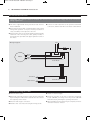
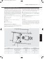
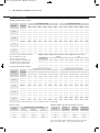
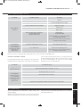
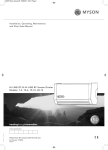
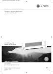
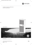
23678 Lo-Line RC manual UK 27/06/2011 09:28 Page 2
Installation, Operating, Maintenance
and After Sales Manual.
LO-LINE RC & LO-LINE RC Heater/Cooler
Models: 6-4, 9-6, 14-10, 19-15
heatingthroughinnovation.
01.06.2011 ISSUE 5
Product Serial Number:
Please leave this manual with the end user.
Part Number: 1370057
Issue 5
23678 Lo-Line RC manual UK 27/06/2011 09:28 Page 3
Contents
1.0
General Information
03
2.0
Heating System Design
03
3.0
Unit Selection/Sizing
03
4.0
Location
03
5.0
Preparation
04
6.0
Fixing
04
7.0
Water Connections
05
8.0
Electrical Connection
06
9.0
Commissioning Procedure
06
10.0
Technical Data
08
11.0
Operating Instructions
09
12.0
Troubleshooting
10
13.0
Maintenance
11
23678 Lo-Line RC manual UK 27/06/2011 09:28 Page 4
LO-LINE RC & LO-LINE RC Heater/Cooler
03
Automatic – the desired room temperature is programmed in
to the unit and the fan speed is automatically adjusted until
the desired room temperature is achieved.
l The LO-LINE should only be used on closed circulation, two
pipe, pump assisted central heating systems (LO-LINE) or
heating and cooling systems (LO-LINE Heater/Cooler).
Fan only – allows user selection of any of the 3 available fan
speeds irrespective of room temperature or water temperature
in the coil.
l The LO-LINE Heater and Heater/Cooler can be used on heat
pump systems.
Fan only with water temperature control – allows the user to
select any of the available fan speeds, which will operate only
if the water temperature in the coil is above 32C. This enables
control of the unit via an externally mounted room thermostat
if desired.
3.0
l This appliance is not intended for use by persons (including
children) with reduced physical, sensory or mental
capabilities, or lack of experience and knowledge, unless
they have been given supervision or instruction concerning
use of the appliance by a person responsible for their safety.
l The minimum side clearance is 100mm.
l The maximum ceiling height is 3m.
l Before proceeding with the installation, the heating system
design must be considered and the unit correctly sized to
meet the heat loss requirements of the room at normal fan
speed.
l This unit is supplied with an infra red remote control system
and has 3 operating modes -
Children should be supervised to ensure they do not play with
the appliance.
This unit MUST NOT be installed in a bathroom or other similar high humidity area.
2.0 Heating System Design
This fan convector must be fitted on a two pipe, pumped
circulation heating system.
For optimum fan convector heating performance the system
must be capable of providing sufficient hot water through the
heat exchanger. This means that:
1. The minimum pipe size from boiler to fan convector must be
15mm.
2. This unit is not suitable for use on microbore pipe-work.
4. The system water must be above 32°C for heating mode.
5. For heat pump applications - see Commissioning Procedure
6. This unit is NOT suitable for one-pipe systems.
7. Optimum performance will require effective balancing of
the whole system.
8. This unit must not be used to replace a radiator in an
existing system unless an adequate flow of water through
the unit can be guaranteed.
3. Where the unit is fitted on to a system with other emitters a
separate circuit for the fan convector should be considered
to provide adequate water flow.
3.0 Unit Selection/Sizing
Heat output performance is given in the Technical Data section
of this manual. Outputs are shown for the three fan speeds,
however, it is important to size the unit to match the calculated
heat loss requirements of the room with the unit operating on
the low fan speed. The higher fan speeds are used in automatic
mode when the room temperature is significantly lower than the
preset temperature.
When establishing the temperature difference, ie mean water to
room temperature, allowance should be made for temperature
drop in the system. It is the water temperature of the unit which
dictates the output.
4.0 Location
l This LO-LINE unit may be fitted to any convenient wall at a
height from floor level that suits the application, providing an
unimpeded flow of warm air into the area to be heated.
l The unit should be mounted on a flat wall, and stud or
partition walls should be avoided to minimise the possibility
of noise transmission.
l The minimum distance from the underside of the unit to floor
level is 150mm.
l For cooling applications, the need for disposal of condensate
may influence the position of the unit.
2.0
l This MYSON LO-LINE fan convector is designed for wall
mounted installation with a minimum installation height of
150mm to the underside of the unit.
4.0
1.0
1.0 General Information
23678 Lo-Line RC manual UK 27/06/2011 09:28 Page 5
04
LO-LINE RC & LO-LINE RC Heater/Cooler
5.0 Preparation
Before proceeding with the installation, unpack the carton
contents and check against the checklist below:
1. LO-LINE or LO-LINE Heater/Cooler unit.
2. 15mm isolating valves (1 pair).
3. Instruction manual.
4. Warranty card.
5. Fixing kit (rubber mounts and cable gland).
6. Remote control handset.
6.0 Fixing
l Using the fixing dimensions (see fig. 1), mark the fixing hole
positions on the wall.
l Tighten the screws into the top two fixing holes leaving about
9mm projecting.
l Drill and plug the wall for No. 8 x 40mm round head wood
screws ensuring that the wall plugs are suitable for the wall
type.
l Press adhesive washers to the wall.
l Remove the backing from the other two self-adhesive
washers and place centrally over the bottom two fixing holes.
l Remove the backing from two of the self-adhesive washers
and place on two of the screws with adhesive side towards
the point.
Dimensions (mm)
62
58 100
B
247
385
min each
side
A
B
C
19-15
1138
1018
974
14-10
854
733
689
9-6
645
526
481
6-4
523
404
359
107
A
150 min
56
C
Unit
Fig. 1
Remove the outer casing as follows:
l Remove the 2 screws from the underside of the unit (see fig. 2).
l Lift off the outer case.
l Fit chassis on to the top two mounting screws and tighten.
l Secure the bottom two fixing points with the remaining two
screws.
Cover Fixing Screws
Fig. 2 Case fixing screw positions
23678 Lo-Line RC manual UK 27/06/2011 09:28 Page 6
LO-LINE RC & LO-LINE RC Heater/Cooler
05
7.0 Water Connections
l Connect unit to system flow and return pipes using the two
15mm isolating valves (see fig. 3).
LO-LINE Heater/Cooler installations with chilled water will
require provision for condensate disposal in accordance with any
local regulations.
Note: To ensure effective venting of the heat exchanger the flow
pipe should be connected to the bottom connection of the heat
exchanger.
A drain tray is fitted for condensate collection within the unit.
This should be connected to a 15mm drain pipe.
Note: For LO-LINE installations pipe-work must not be routed
directly underneath the unit as this will adversely affect the
operation of the integral room thermostat. If this cannot be
avoided, the pipe-work must be boxed to prevent heat rise.
Note: External pipe-work carrying chilled water must be
insulated. Use a suitable sealant as necessary to ensure that
condensate does not spill or leak. Once connection to the
system flow and return pipes is made, any exposed internal
15mm pipework and isolating valves must be insulated.
l Ensure system is flushed in accordance with recognised best
practice and a suitable inhibitor is added to the system as
necessary.
72
5.0
l Open valves fully, check pipe connections for leaks and vent
the heat exchanger - see Commissioning Procedure.
68
191
7.0
6.0
130
57
Fig. 3
57
99
99
23678 Lo-Line RC manual UK 27/06/2011 09:28 Page 7
06
LO-LINE RC & LO-LINE RC Heater/Cooler
8.0 Electrical Connection
WARNING: This appliance must be earthed. The electrical installation must comply with local or national
wiring regulations.
l This unit is supplied with factory fitted test leads. Remove
these and discard.
l Connect live and neutral wires to the power board terminal
connections, and the earth wire to the chassis earth terminal.
l A fused electrical spur with a maximum 3A fuse and a switch
having 3mm separation on all poles must be provided in an
easily accessible position adjacent to the unit.
l Electrical cable entry to the unit should be made through the
underside of the unit using the cable gland provided, or
through the hole provided at the upper right hand corner of
the chassis.
Wiring Diagram
LN
O O
OO
Motor
Brown
Blue
White
Yellow
Power Board
Air Sensor
Water Sensor
Control Board
9.0 Commissioning Procedure
l Fill and vent the system.
l Switch on electrical supply.
l Open both valves fully and vent air from the heat exchanger
by unscrewing the air bleed valve situated above the valves in
the angled top of the chassis.
l Check the operation of the unit in automatic and manual
modes (LO-LINE) or heating and cooling modes (LO-LINE
Heater/Cooler) by following the operating instructions.
l Check for leaks at pipe connections.
l When installation and commissioning are complete, hand over
instruction manual to end-user.
l Refit the outer case and secure using the 2 fixing screws.
23678 Lo-Line RC manual UK 27/06/2011 09:28 Page 8
LO-LINE RC & LO-LINE RC Heater/Cooler
9.0 Commissioning Procedure
07
(continued...)
Heat Pump and Low Water Temperature Systems
In heating mode, the control system brings the fan on when the
water in the coil reaches 32°C. For low water temperature systems,
eg heat pump systems, it is possible to switch off the boost speed
option in automatic mode so that the unit runs in medium or normal
fan speeds depending on demand. This means low outlet air
temperatures from the unit are avoided when the room temperature
is low in relation to the set temperature.
This facility can be switched on or off by following the instruction
below
l Isolate electrical supply.
The displayed temperature calibration function enables
calibration in heating mode of the displayed temperature to the
actual room temperature using the following procedure:
l Run the fan convector until room conditions stabilise.
l Press the ‘On/Off’ key and ‘+’ key for 5 seconds (the display
will flash, alternating between ‘ro’ and the calibration
temperature.
l Calibrate the displayed room temperature by using the
‘+’ and ‘-’ keys with the fan running.
l Press the ‘On/Off’ key to finish
l Remove outer cover.
l Change switch 1 position according to requirements
(see fig. 4).
l Refit outer cover.
l Switch on electrical supply.
Displayed Temperature Calibration
Fan Pulse
Fan pulse mode causes room air to be drawn over the air
temperature sensor periodically to maintain room temperatures
more effectively. In certain circumstances, for example when
units are over-sized in relation to the heat loss of the room, it
may be necessary to turn off this function. Use dipswitch 3
according to requirements.
9.0
8.0
Depending on the location of the unit there may be a difference
between the temperature at the unit and the temperature in the
middle of the room being heated.
Dipswitches
Fig. 4
Switch
Switch Down
Switch Up
1
Auto Fan Speed Selection
2 Speed
3 Speed
2
Heating / Cooling
Heating
Heating & Cooling
3
Fan Pulse
Off
On
4
Temperature Display
°F
°C
23678 Lo-Line RC manual UK 27/06/2011 09:28 Page 9
08
LO-LINE RC & LO-LINE RC Heater/Cooler
10.0 Technical Data
Heating Performance Data
Heat Output (watts)
Model
Fan Speed
19-15
14-10
9-6
6-4
Temperature Difference (°C)
45°
50°
55°
60°
65°
6-4
90°
99°
108°
117°
2921
3268
3613
3956
4298
4639
9970
11154
12331
13503
14670
15832
3351
3748
4144
4538
4930
5321
11436
12783
14144
15488
16826
18159
Boost
3751
4197
4640
5081
5520
5957
12803
14323
15836
17340
18839
20331
Normal
1922
2150
2377
2603
2828
3052
6559
7338
8113
8884
9652
10416
Medium
2367
2648
2928
3206
3483
3759
8080
9039
9993
10943
11889
12831
Boost
2803
3136
3467
3796
4125
4451
9567
10703
11833
12957
14077
15192
Normal
1098
1228
1357
1486
1617
1743
3748
4191
4633
5073
5519
5948
Medium
1437
1608
1777
1945
2114
2282
4904
5486
6066
6642
7216
7788
Boost
1811
2026
2240
2453
2665
2875
6182
6916
7645
8372
9096
9816
Normal
741
829
916
1003
1090
1176
2528
2829
3127
3424
3720
4015
Medium
843
943
1043
1142
1240
1339
2877
3218
3558
3896
4233
4568
Boost
1162
1300
1437
1574
1710
1845
3965
4436
4905
5371
5836
6297
Fan Speed
9-6
81°
Normal
Approximate Hydraulic Resistance through Fan Convectors
Litres/h
455
340
227
113
Cooling Performance Data
14-10
72°
Medium
Flow Rate Correction Factors:
455 ltr/h (100 gal/h) multiply by 1.06.
227 ltr/h (50 gal/h) multiply by 0.96.
113 ltr/h (25 gal/h) multiply by 0.85.
19-15
Temperature Difference (°F)
40°
Tested in accordance with BS 4856 Part 1.
Flow rate 340 ltr/h (75 gal/h).
Model
Heat Output (Btu/h)
kPa
mm wg
6-4
9-6
910
514
235
47
998
520
121
97
14 - 10 19 - 15
1240
719
324
75
1670
954
469
77
6-4
9-6
14 - 10 19 - 15
8.98
5.06
2.35
0.45
9.85
5.10
1.18
0.97
12.20
7.00
3.20
0.75
16.40
9.40
4.60
0.82
Cooling Performance (watts)
Cooling Performance (Btu/h)
Air-Mean Water Temperature Difference (°C)
Air-Mean Water Temperature Difference (°F)
15°
20°
25°
27°
36°
45°
Tot.
Sens.
Tot.
Sens.
Tot.
Sens.
Tot.
Sens.
Tot.
Sens.
Tot.
Sens.
Normal
1340
1104
2002
1345
2734
1452
4572
3767
6831
4589
9328
4954
Medium
1464
1203
2187
1511
2987
1632
4995
4105
7462
5156
10192
5568
Boost
1533
1305
2291
1656
3128
1725
5231
4453
7817
5650
10673
5886
Normal
877
754
1310
969
1788
1034
2992
2573
4470
3306
6101
3528
Medium
1032
878
1542
1113
2106
1159
3521
2996
5261
3798
7186
3955
Boost
1228
1052
1835
1347
2505
1427
4190
3589
6261
4596
8547
4869
Normal
499
423
745
535
1018
553
1703
1443
2542
1825
3473
1887
Medium
600
507
896
639
1223
655
2047
1730
3057
2180
4173
2235
Boost
710
581
1061
770
1448
957
2423
1982
3620
2627
4941
3265
Normal
321
277
480
357
655
383
1095
945
1638
1218
2235
1307
1143
1996
1464
2723
1549
1355
2528
1795
3453
2231
Medium
391
335
585
429
798
454
1334
Boost
496
397
741
526
1012
654
1692
Tested in accordance with BS 4856 Part 2. Flow rate 340 ltr/h. Relative humidity 50%.
Noise Levels
Model
Weight, Water Content and Motor Power
Sound Pressures at 2.5m (dBA)
Water
Content (l)
Unpacked
Weight (kg)
80
0.3
7.7
62
0.32
9.1
9-6
35
0.56
12.7
6-4
35
0.75
15.7
Model
Motor
Power (W)
38.6
19-15
40.1
14-10
29.6
38
31.7
40.7
Normal
Medium
Boost
19-15
27.2
31.8
14-10
23.1
28.5
9-6
21.6
6-4
23.7
Test Pressure 20bar (2MPa) Maximum Working Pressure 10bar
Water connections 15mm Electrical supply 230V - 50Hz
23678 Lo-Line RC manual UK 27/06/2011 09:28 Page 10
LO-LINE RC & LO-LINE RC Heater/Cooler
09
11.0 Operating Instructions
Description
This LO-LINE unit is fitted with a control system that provides
3 different operating modes. In automatic mode the desired
temperature set point is selected and the unit will adjust the fan
speed according to the difference between the actual room
temperature and the set point. When the room temperature
reaches the set point the fan will switch off and thereafter will
continue to cycle on and off to maintain the room temperature.
The temperature set point range is 15 - 35°C.
In manual mode, with water temperature control, any of the 3
fan speeds can be selected and the fan will operate when the
water temperature in the coil is greater than 32°C. This means
that heating performance can be controlled manually, and the
unit could be controlled via an external room thermostat.
The unit can be controlled using the infra red remote control
handset supplied with the unit (see fig. 5) and also using
the control panel on the unit (see fig. 6). If necessary, however,
the control panel can be locked electronically to prevent
tampering once the controls have been set (see over).
In manual mode the automatic temperature control is
overridden and any of the three fan speeds can be operated
inrespective of the water temperature in the unit. This means
that air circulation can be provided in summer for example, or
that heating performance can be controlled manually.
Fig. 5
Fig. 6
Display
Heating
Power button
Switches unit on & off
‘+/-’ button
Adjust temperature set point from
15 - 35°C
Scrolls into F1, F2 or F3 manual mode
The unit will only operate in heating mode when the central
heating boiler is on, the pump is running and the system
water temperature is greater than 32°C. Ensure the boiler is
on, and set timer, boiler controls and room thermostats as
necessary.
11.0
Controls
10.0
The remote control hand set takes 2 AAA batteries (not supplied).
23678 Lo-Line RC manual UK 27/06/2011 09:28 Page 11
10
LO-LINE RC & LO-LINE RC Heater/Cooler
11.0 Operating Instructions
(continued...)
Operation
Display
Manual
Power off
No Display
Manual mode can be used for air circulation without heat or for
manual control of the heating function.
Switch on supply to unit
(unit off)
for 30 seconds
Use ‘+’ to scroll beyond 35°C
Or use ‘-’ to scroll below 15°C
Selected fan speed displayed
Supply on / unit off
Continuous
fan only
Switch on unit
Set point flashes for
approx 5 secs, then
Ambient temperature
displayed
Fan & water
temperture
(water inlet >32°C)
Scrolling back out of manual using the ‘+’ or ‘–’ button will revert
the unit back to last temperature set point.
Cooling Mode
Use ‘+/-’ to adjust
set point
Set point flashes for
approx 5 secs, then
l Close the heating system and isolate any other heat emitters.
l Open the cooling water system.
l Ensure cooling is on, and set cooling unit timer and controls
as necessary.
Ambient temperature
The ambient temperature is always displayed unless the water
temperature falls below 32°C*, or if the set point is being
adjusted.
Water temp <32°C
Shows both power
& unit on
*32°C in heating and above 20°C in cooling.
Cooling operation works in exactly the same way as heating.
Follow the procedure above to set the unit controls.
Locking Unit Controls
The control panel on the main unit can be locked electronically
to prevent interference once the controls have been set. After
setting the unit to the desired temperature setting and with the
unit in running mode, press the On/Off button on the main unit
for about 6 seconds until the two middle horizontal bars appear
on the display. The horizontal bars will disappear after about 6
seconds and the unit is in key lock mode.
If any of the unit controls are pressed the horizontal bars will
reappear to show the key lock mode is activated, however,
during this mode the handset controls remain functional.
To unlock the system press the On/Off button for about 6
seconds until the horizontal bars disappear.
12.0 Troubleshooting
Once installed this fan convector becomes part of a complete
heating system that will generally include a boiler, pump, other
emitters such as radiators and fan convectors, and a number of
heating controls, dependent on system complexity. An apparent
problem with this unit may be the result of system controls being
incorrectly set and can be solved easily without calling out your
installer or MYSON Service. Before calling your installer or
MYSON Service, please carry out the checks listed opposite.
Note: If you call out MYSON Service to a fault detailed opposite,
or to repair a fault caused by incorrect use, a call out charge will
be made.
23678 Lo-Line RC manual UK 27/06/2011 09:28 Page 12
LO-LINE RC & LO-LINE RC Heater/Cooler
12.0 Troubleshooting
11
(continued...)
Problem
Possible Causes
Remedy
Unit switched off
Turn on
Temperature set point reached
Increase temperature set point
Unit not switched on at fused spur
Switch on at spur
Heating Mode -
Fuse blown at fused spur
Replace fuse
No Fan
Unit isolating valves shut
Open valves
Water temperature reaching fan
convector below 32°C
(Heater model only)
Check boiler Programmer ON
Boiler ON and set to high with central
heating pump running
Note: Operation of fan convector can be checked by
switching to manual fan setting
Heating Mode
Low water temperature to unit
Turn up boiler thermostat
Poor water flow
Vent air from heating system
(Heater model only)
poor heating
performance and/or
unit cycles on
water sensor
Note: Operation of fan convector can be checked by
switching to manual fan setting
If the fan convector is still faulty after checking the above, call your installer or MYSON Service.
Common Installation Faults
For optimum performance, this unit must be correctly sized to
match the heat loss requirements of the space it is required to
heat, and the heating system must be correctly designed to
provide adequate flow of hot water to the unit (refer to section
2). If the recommendations in section 2 are not followed,
problems may arise as detailed below.
Problem
Possible Causes
Poor heating performance
Unit incorrectly sized for heat loss of room
(Heater model only)
Boiler thermostat set too low
Heating Mode
(Heater model only)
poor heating
performance and/or
unit cycles on
water sensor
Lack of flow to fan convector Pump set on low setting
Isolating valves not fully open
System incorrectly balanced with unit starved of hot water flow
11.0
Pipe sizing to unit too small
Maintenance should be restricted to occasional removal of dust
and lint around the unit. The outer surface may be wiped over
with warm water and mild detergent taking care to avoid water
entering the grille areas.
13.0
Before undertaking any maintenance activity isolate the
electrical supply.
12.0
13.0 Maintenance
23678 Lo-Line RC manual UK 27/06/2011 09:28 Page 1
MYSON Eastern Avenue, Team Valley, Gateshead, Tyne & Wear NE11 0PG, UK
T: 0845 402 3434, F: 0191 491 7568, [email protected], www.myson.co.uk
Serial Number Location:
Inner chassis position
heatingthroughinnovation.
After Sales Service:
Spare parts and technical help on all Convector products are available from MYSON Service.
01.06.2011 ISSUE 5
MYSON Service, Somerden Road, Hull, East Yorkshire HU9 5PE
T: 01482 713927, F: 01482 789056, [email protected]