1
t:7_!:_LI_;
_;:,_;;
i;'7,. -"L:,L_
_!:!L;k:::L::,_:
7:_=!:i=:;i_: '
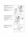
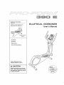
Model No. 831,,23943,0
Serial No.
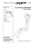
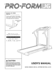
ELLIPTICAL
Write the serial number in the
space above for reference.,
• Operation
• Maintenance
- Part List and Drawing
Sears, Roebuck and Co,
Hoffman Estates, IL 60179
tr,,i it i
EXERCISER
User's
. Assembly
,t-k, :tt,,_ft N TI
_i!=::;
ii.:_
¸
.
Read all precautions and instructions in this manual before using
this equlpmenL Keep this manusl
for future reference. _
Manual
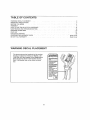
TABLE
WARNING
OF CONTENTS
DECAL PLACEMENT
.................................................................
IMPORTANT PRECAUTIONS
........................................................................
BEFORE YOU BEGIN .......................................................................
2
3
4
ASSEMBLY ......................................................................................
HOW TO USE THE ELLIPTICAL EXERCISER
.........................................................
5
14
MAINTENANCE AND TROUBLESHOOTING
.....................................................
EXERCISE GUIDELINES
......................................................................
18
20
PART LIST
EXPLODED
21
22
.......................................................................................
DRAWING
................................................................................
ORDERING REPLACEMENT PARTS ..............................................
90 DAY FULL WARRANTY
............................................................
WARNING
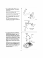
DECAL
PLACEMENT
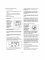
This drawing shows the Iooalion(s) ol the warning
decal(s),, If a decal is missing or illegible, call
1-B00-533-,1333 and request a free replacement
decal° Apply the decal in the location shown.
Note: The decal(s) may not be shown at actual
size,
Back Cover
Back Cover
iMPORTANT
PRECAUTIONS
WAR NING: TOreduoe
the risk
of serious
Injury, read all Important
precautions
and
instructions in this manual and all warnings on the elliptical exerciser before using the elliptical
exerciser. Sears assumes no responsibility for personal injury or property damage sustained by or
;:through the use of this PrOduct.
1. Before beginning any exercise program,
consult your physician. This is especially
Important for persons over age 35 or persons with pre-existing health problems.
B_
;:2;: It Isthe responsibility of the owner to ensure
that el! users of the elliptical exerciser are
adequately Informed of all precautions,
9,, Hold the handgrip
pulse sensor or the upper
body arms when mounting, dismounting, or
using the elliptical exerciser.
3. =The elliptical exerciser is intended for home
use only, Do not use the elliptical exerciser
tn a commercial, rental, or institutional settlng,
10. Keep your back straight while using the
elliptical exerciser; do not arch your back,
11 The pulse sensor is not a medical device
Various factors, including the user's movement, may affect the accuracy of heart rate
readings, The pulse sensor is intended only
as an exercise aid in determining heart rate
trends in general.
4; _:Keepthe elliptical exerciser indoors, away
from moisture and dust. Place the elliptical
exerciser on a level surface, with a mat
beneath it to protect the floor or carpet, Make
sure that:there is at leasl 3 fl, (0,9 m) of clearance In the front and rear of the elli ptlcal
exerciser and 2 ft. (0,6 m) on each side.
5.
= ,
12. When you stop exercising,
to slowly come to a stop.
Inspect and properly tighten a!l parts regularly_ Replace any worn parts immediately.
.
Keep children under age 12 and pets away
from the elliptical exerciser at all times.
7.
The elliptical exerciser should not be used
by persons weighing more than 250 Ibs_
(113 kg).
allow the pedals
13. Over exercising may result In serious Injury
......
6.
Wear appropriate exerctse clothes when
exercising;
do not wear loose clothes that
could become caught on the elll pttcal exerciser. Always wear athletic shoes for foot
protection.
or death. If you feel faint or if you experience
pain while exercising, stop immediately and
cool down.
I4o Use the elliptical exerciser
tn this manual°
only as described
3
i
BEFORE
YOU BEGIN
Thank you for purchasing the PROFORM" 390 E elliptical exerciser, The 390 E elliptical exerciser provides
an array of features designed to make your workouls
at home more effective and enjoyable,
For your' benefit, read this manual carefully before
you use the elliptical exerciser, If you have queslions after reading this manual please see the back
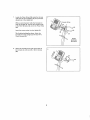
Upper Body Arm
cover of this manual. To help us assist you, note the
product model number and serial number before corn
tacting us. The mode] number and the location of the
serial number decal are shown on the front cover of
this manual,
Before reading further, please tamiliafize yourset[ with
lhe paris that are labeled in the drawing below.
Fan
Pulse Sensor
Console
Handlebal
Water Bottle Holder'
Pedal Disc
Handle -
Leveling Foot
*Water bottle is not included
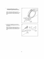
ASSEMBLY
Assembly requires two persons. Place aii parts of the elliptical exerciser in a cleared area and remove the
packing materials. Do not dispose of the packing materials until assembly is completed.
In addition
to the included
tool(s), assembly
requires
a Phillips screwdriver
_
o
As you assemble the elliptical exerciser, use the drawings below to identify small parts. The number in parenflleses below each drawing is the key number of the part, from the PART LIST near the end o! this manual. The
number foflowing the parenlheses is the quanl[ly needed for assembly.. Note: if a part Is not in the hardware
kit, check to see if it has been preassembledo
If a part Is missing, call 1-888-533-1333,
M8 Jam Nut
(77)-,4
M8 Washer
{33)-2
M10 Split
Washer (78)-10
M4 x 48ram
Screw (89)-2
M4 x 16mm
Screw (92)-7
D
M8 x 20ram
Patch Screw
M8 x 45mm Button
Bolt (76)--4
MIO x 20ram Patch
Screw (79)-7
(80)-2
MtO x 48mm Patch
Screw (75)-6
MtO x 85mm Patch Screw (82)-4
Shoulder Patch Bott (3t)-2
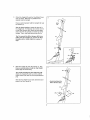
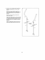
Tomake
assembly easier, read the
: ::
::information on page5 before you begln,:
:::
While a second person lifts the rear of the
Frame (1), attach the Rear Stabilizer (7D) to the
Frame with two MIO x 85mm Patch Screws
(B2),.
82
2_
Orient the Front Stabilizer (73) so that the
"Front" sticker is facing away from the front of
the Frame (1),
73
While a second person lifts the front of the
Frame (1), allach the Front Stabilizer (73) to lhe
Frame with two MtO x 85mm Patch Screws
(82)°
6
B2
3,
Orient the Upright (2) and the Top Shietd Cover
(37) as shown., S_ide the Top Shield Cover
upward onto Ihe Upright,
Have a second person hold the Upright (2) near
the Frame (I).
See the Inset drawing. Locate the wire tie in
tl_e Upright (2) ]]e the lower end of the wire tie
to the Wire Harness (42), Next, pull the upper
end of the wire tie upward out ot the top o[ the
Uptight, Then, untie and discard ihe wire tie,
Tip: To prevent the Wire Harness (42) from
falling into the Upright (2), secure the Wire
Harness with a rubber band or a piece of
tape.
4,
Slide the Upright (2) onto the Frame (!), Tip;
Have a second person hold the Top Shield
Cover (37) out of the way.
Tip: Avoid pinching the Wire Harness (42).
Attach fhe Upright (2) with four M!0 x 20mm
Patch Screws (79) and four Mt0 Split Washers
(Te).
Slide the Top St_ietd Cover (37) downward
press it into the Frame (t)
and
Avoid pinching the
Wire Harness {42)
79
7
>79
5_
See the upper drawing. To avoid pinching or
damaging the Pulse Wires (28) while you
assemble the Handlebar (39), perform the folbwing actions:
Insert the end of the tetl Pulse Wire (28) inside
the lett side of the Handlebar (39),
39
Then, insert the end of the right PuIse Wire (26)
inside _he righl side of the Handlebar (39)o
See the lower drawing,, Have a second person
hold the Handlebar (39) in place around the
Upright (2)..
28
Tip: Avoid pinching the wires. Attach the
Handlebar (39) to the Upright (2) with three MI0
x 20ram Patch Screws (79).
79
39
Avoid pinching
lhe wires
6,
The Console (4) can use four D batteries (not
included); alkaline batteries are recommended,,
IMPORTANT= If the Console has been
exposed to cold temperatures, allow it to
warm to room temperature before Inserting
batteries. Otherwise, you may damage the
console displays or other electronic
components. Remove the screws, remove the battery
covers, insert the batteries into the battery compartments, and reattach the ba!tery covers.
Make sure to orient the batteries as shown
by the diagrams inside the battery
ments.
Screws
Battery
Covers
Batteries
compartBatteries
To purchase a power supply, call your local
Sears store. To avoid damaging the console,
use only a manufacturer=supplied
power
supply. Plug one end of the AC adapter into the
jack on the console; plug the other end into an
outlet installed in accordance with all local
codes and ordinances,,
4
8
7,
Locate the Pulse Wires (28) inside the left and
right sides of the Handlebar (39) and pull _hem
upward out of the Upright (2).
Console Wires
While a second person holds the Console (4)
near the Upright (2), connect the console wires
to the Wire Harness {42) and to the Pulse Wires
(28)..
Insert the excess wires into the Upright (2).
28
Tip; Avoid pinching the wires° Attach the
Console (4) to the Upright (2) with four M4 x
16ram Screws (92)
'39
Avoid
pinching
the wires
8_
Attach the Console Cover (32) to lhe back of
lhe Console (4) with two M4 x 4Bmm Screws
(89)
32
Identify
theLeftandRight
Upper
Body
Arms(8.
9),which
aremarked
with"Left"
and "Right"
stickers
Orient the Left Upper Body Arm (8) and an
Upper Body Leg (6) as shown, Make sure that
the hexagonal
holes are in the indicated
location°
lnsed the Left Upper Body Arm (8) into the
Upper Body Leg (6),,
Attach the Left Upper Body Arm (8) wilh two M8
x 45ram Button Bolts (76) and two M8 Jam Nuts
(77). Make sure that the Jam Nuts are in the
hexagonal holes. Do not tighten the Button
Bolts yet.
Attach the Right Upper Body Arm (9) to the
other Upper Body Leg (6) in the same way.
76
10
10, Appty a generous amount 01 the included
grease to the axles on the Upright (2)
10
Orient the Left and Right Upper Body Arms (8,
9) as shown, and slide them onto the left and
rigllt sides o! Ihe Upright (2).
Attach each Upper Body Arm (8, 9) with an M8
x 20mrn Patch Screw (80) and an M8 Washer
(33),
11. Apply a small amount of grease to a Shoulder
Patch Boll (31)..
1t
While a second person holds the front end of
the Right Pedal Arm (49) inside the bracket on
ll_e righ! Upper Body Leg (6), insed 1he
Shoulder Patch Bolt (31) through the right
Upper Body Leg and the Right Pedal Arm
76
Tigh!en the Shoulder Patch Bolt (31) inlo the
welded nut on the right Upper Body Leg (6).
Repeat this step to attach the Left Pedal Arm
(not shown) to the left Upper Body Leg (6).
Tighten the MB x 45ram Button Bolts (76).
11
12_ See the inset drawing, identity a Pivot Cover A
(19). which has hooks+ and a Pivot Cover B
(22), which has tabs
12
Press a Pivot Cover A (19) and a Pivot Cover B
(22) together around lhe Right Upper Body Arm
(9)
Repeat this step for the other
elliptical exerciser,
side of the
Tabs _/_
Tip: Make sure that the Pivot Covers
are positioned
as shown,
(19, 22)
_Hooks
13
Orient the Front Upright Cover (16) so that the
indicated arrow is pointing upward
Press the Front Upright Cover (16) into the
Rear Upright Cover (3)
Press the Water Bottle Holder (5) into the Rear
Upright Cover (3)
92
14. Press a Front Leg Cover (20) and a Rear Leg
Cover (21) logether around the right Upper
Body Leg (6).
9
2
I
t3.. Atlaeh the Rear Upright Cover (3) to the Upright
(2) with three M4 x 16ram Screws (92)_
8
14
Repeat this step for the other side of the
elliptica! exerciser.
12
J"
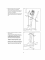
t5. Identify' 1he Right Pedal (t3), which is marked
wilh a "Right" sticker.
Attach the Righl Pedal (13) to the
Arm (49) with three MIO x 48mm
(75) and three M10 Split Washers
sure to use the center hole and
15
13
Right Pedal
Patch Screws
(TB)_ Make
the two
outer holes to attach the Right Pedal.
Attach the Left Pedal (not shown) to the Left
Pedal Arm (not shown) in the same way,
49
75
16. Press the Rear Shield Cover (59) onto the Lelt
and Right Shtelds (44, 45)..
16
44
45
59\
17 Make sure that all parts of the elliptical exerciser are properly tightened, Note: Some hardware rnay be
left over after assembly is completed To protect the floor or carpet from damage, place a mat under the
elliptical exerciser.
13
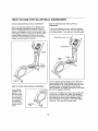
HOW TO USE THE ELLiPTiCAL
HOW TO MOVE THE ELLIPTICAL
EXERCISER
EXERCISER
HOW TO EXERCISE
EXERCISER
Due to the size and weight of the elliptical exerciser, moving it requires two persons. Stand in
front of the elliptical exerciser, hold the upright, and
place one foot against one of the front wheels Pull on
the upright and have a second person iilt the handle
until the elliptical exerciser will roll on the wheels..
Carefutiy move the elliptical exerciser to the desired
location, and then lower it to the floor
ON THE ELLIPTICAL
To mount the elliptical exerciser, hold 1he handlebars
or the upper body arms and step onto the pedal that is
in the lowest posltion_ Then, step onto the other pedal
Upper Body Arms
Handlebars_@
]ht
Peda
Pedals
)_
"_f
[]F[
/
Disc
Place
your foot
here
HOW TO LEVEL THE ELLIPTICAL
If the elliptical
exerciser rocks
sfightiy on your
{loor during use,
turn one or both
To dismount the elliptical exerciser, wait until the pedals come to a complete stop,. Note: The elliptical
exerciser does not have a free wheel; the pedals
will continue to move until the flywheel stops.
When the pedals are stationary, step off the highest
pedal first Then, step oil the lowest pedal..
of the leveling
feet beneath the
rear stabilizer
until the rocking
motion is eliminated.
EXERCISER
Push the pedals unlil they begin to move with a continuous motion Note; The pedal discs can turn In
either direction° It Is recommended
that you move
the pedal discs in the direction
shown by the
arrow; however, for variety, you can turn the pedal
discs in the opposite direction,
Leveling
Feet
14
FEATURES
OF THE CONSOLE
The advanced console offers an array of features
designed to make your workouts more effective and
enjoyable
When you use lhe manual mode o! the console, you
can change lhe restsfance of the pedals with the touch
of a bullon. As you exercise, the console will provide
continuous exercise feedback. You can even measure
your head rate using the handgrip pulse sensor
You can even connect your MP3 player or CD player
to the conso!o sound system and lislen to your favorite
music or audio books while you exerc_s8
To use the manual mode, see page 16_To use a
preset workout, see page 17. To use the sound
system, see page t7
Note: Before using the console, make sure thatbatteries are installed (see assembly step B on page 8)_ It
lhere is a sheet of clear plaslic on the display, remove
the plastic.
The console oilers twelve preset workouts--seven
weight toss workouts and five performance workouts
Each preset workout automatically changes the resistance of the pedals as il guides you through an
effective workouL
15
HOW TO USE THE MANUAL MODE
1.
The lower left display--This
display will show the
distance (total number of revolutions) that you
have pedaled
Turn on the console,
The lower right display--This
display wili show
your pedaling speed in revolutions per minute
(rpm) and the approximate number of calories you
have burned,
Press any button or begin pedaling to turn on the
console
When you turn on Ihe console, the display wiii
tighL A tone will sound and ttle consote will be
ready for use,
2.
Select the manual
The lower right display will also show your heart
rate when you use lhe handgrip pulse sensor (see
slop 5).
mode.
The right display--This display will show a track
that represents 640 revolutions (tt4 mile or 400
meters), As you exercise, indicators will appear in
succession around the track until the entire track
When you turn on the console, the manual mode
wilt be setecled
if you have
selected a workout,
reselect the manual
appears, The lrack will then disappear and the
indicators will again begin to appear in succession
[ n,nn
mode by pressing
the Weight Loss
Workouts or the
Performance
Workouts button
5.
if there are sheets
repeatedly until
zeros appear in the
displays.
3,
of clear plastic on
Contacts
the metal contacts
on the handgrip
pulse sensor,
remove the plastic.
In addition, make
sure that your
hands are clean,
To measure your heart rate, hold the handgrip
I
Track
Begin pedaling and change the resistance of
the pedals as desired.
As you pedal, change the resistance of the pedals
by pressing the Resistance increase and decrease
buttons,,
pulse sensor with your palms resting against the
melal contacts° Avoid moving your hands or
gripping the contacts tlghtly_
f'Jote: After you press the buttons, it will take a
moment for the pedals to reach the selected resistance level.
4.
Measure your heart rate if desired,,
When your pulse is detected, a heart-shaped symbol wili flash in the display and then your heart rate
witt be shown For the most accurale heart rate
Follow your progress with the displays,
reading, hold the contacts for at _east t5 seconds,,
The upper display--This display will show the
elapsed time and the resistance level of the pedals
each time the resistance level changes
If your heart rate is not shown, make sure that your
hands are positioned as described,, Be careful not
to move your hands excessively or to squeeze the
racial contacts tightly. For optimal performance,
clean the metal contacts using a soft cloth; never
use alcohol, abrasives, or chemicals to clean
the contacts.
TIME
8" !I
.SO -;,B'
DISTANCE
M
6.
!
Turn on the fan if desired°
The fan has high and low speed settings, Press
the Fan button repeatedly to select a fan speed or
to turn off Ihe '_an,,
SPEED
Note: If the pedals do not move for about thirty
seconds, the fan witl turn off automatically
Note: During a workout, the display will show tile
time remaining in lhe workout.
16
7_
When you are finished exercising,
will turn off automaticatly_
the console
At the end of each segment of the workout, a
series of tones will sound and the next segment of
the proli{e will begin to flash if a different resistance level is programmed for the next segment,
the resistance level wil! flash in the display for a
{ew seconds to alert you The resistance of the
pedals will then change
if the pedals do not move for several seconds, a
series ol tones will sound, the console will pause,
and the time will flash +nthe displays,
ti the pedals do nol move for several minutes, the
console wilt turn ofl and the display will be reset,
t{ the resistance level for lhe current segment is
too high or loo low, you can manually override the
selling by pressing the Resistance buttons,
However, when the current segment ends, the pedals will aulomatically adjust to the resislance level
for the next segment,
HOW TO USE A PRESET WORKOUT
1+ Turn on the console,
See step 1 on page 16.
II you stop pedaling {or several seconds, a series
of tones will sound and the workout will pause.
2_ Select a preset workout.
To select a preset
workout, press the
Weight Loss
Workouts or the
Performance
Workouls button
repeatedly unt+l the
name of ltle
desired workout
To restart the workout, simply resume pedaling+
The workout wil! continue until the last segment
the profile flashes and the last segment of the
workout ends
} Jlfl
tI
U,ULJl
appears in the
upper display.
I +I IIII111
of
Note: It you continue Io pedal after the workout is
completed, the display will continue to show exercise feedback; however, the display will not show
the elapsed time until you select the manual mode
or a new workout,
I
IJl=,=_==l
Prolile
When you select a preset workout, the duration ol
lhe workout will appear in the upper display and a
profile of the resistance levels of the workout will
scroll across the center display
4, Follow your progress with the display_
See step 4 on page 16
5.
Measure
your heart rate if desired+
See step 5 on page 16
Note: Complete profiles of the preset workouts are
pr+nted on the sides of the console.,
6.
3+ Begin pedaling to slart the workout+
Each workout is divided into 30 one+minute segments. One resistance +evet is programmed for
each segment, Note: The same resistance level
may be programmed lot consecutive segments
During the workout, the workout prolile wilt show
your progress (see the drawing above)The
{lashing segment of the profile represents the current
segment of the workout, The height ol the flash+ng
segment ind+cates the resistance levet for the current segment,
Turn on the fan ff desired.
See step 6 on page 11_
7_
When you are finished exercising,
will turn off automatically.
the console
See step 7 on this page
HOW TO USE THE SOUND SYSTEM
To play music or audio books through lhe console
sound system while you exercise, plug the audio cable
into the jack on the console and inio the jack on your
MP3 player or CD player; make sure that the audio
cable is fully plugged in.
Next, press the play bulton on your MP3 player or CD
player Adjust the volume level using the volume control on your MP3 player or CD player
17
MAINTENANCE
AND TROUBLESHOOTING
_nspect and tighten all parts of the elliptical exerciser
regularly. Replace any worn parts immediately.
44
To clean the elliptical exerciser, use a damp cloth and
a small amount of mild soap IMPORTANT: To avoid
damage to the console, keep liquids away from
the console end keep the console out of direct
sunlight.
CONSOLE
92
TROUB LES HOOTING
if the console displays become dim, the batteries
should be replaced; most console problems are the
resutl of tow batteries.. See assembly step 6 on page 8
for replacemeni inslructions.
92
If the handgrip pulse sensor does not function propedy, see step 5 on page t6.
Next, loosen the Pivol Screw (88) Then, tighten the
Drive Belt Adjustmenl Screw (72) until the Drive Bait
(46) is tight.
HOW TO ADJUST THE DRIVE BELT
tf you can feel ll_e pedals slip while you are pedaling,
even when the resistance is adjusted to the highest
level, the drive belt may need to be adjustedr
To adjust the drive belt, you must remove the left
pedal, the lop shield cover, the rear shield cover, and
the left shield.
First, see step 15 on page t3 and remove the left
pedal
Nexl, see step 16 on page 13 and remove lhe rear
shield cover,
Then. see step 4 on page 7 and release the top shield
cover from the left shield Slide the top shield cover
upward.
Remove the M4 x 16mm Screws (92) from the Left
Shield (44) and then gently move the Left Shietd outward over the Left Pedal Arm (t4)-
When the Drive Belt (46) is light, tighten the Pivof
Screw (Be),
Then, reattach the left shield, the rear shield cover, the
top shield cover, and the left pedal.
18
HOW TO ADJUST THE REED SWITCH
Locate the Reed Switch (58) Loosen. but do not
remove, the M4 x 16ram Screw (92)
It the consofe does not display correct feedback, the
reed swilch should be adjusted
To adjust the reed switch, you must remove the right
disc cover and the right pedal disc
Using a fla! screwdriver,
(18).
remove the right Disc Cover
Then, remove the M8 x 14mm Button Screws {81)
from the Right Pedal Disc (27), and gently rotate the
Right Pedal Disc out of the way.
Next, rotate the Crank Assernbly (24) until a Magnet
(41) is aligned with the Reed Swilch (58),_Slide the
Reed Switch slightly toward or away from the Magnet_
Then. retighten the M4 x 16mm Screw (92).
Rotate the Clank Assembly (24) tar a momenL Repeat
these actions until the console displays correct feedback.
When the reed switch is correc=ly adjusted, reattach
the right pedal disc and the right disc cover,
19
EXERCISE
GUIDELINES
A WARNING: Be,ore
begl.ni.g
t.ls
or any exercise program,
consult your physi-
cian. This is especia!ly important for parsons
over age 35 or persons with pre-exlstfng
health problems;
The pulse sensor Is not a medical device.
Variousfactors may affect the accuracy of
heart rate readings, The pulse sensor is
Intended only as an exercise aid in determining heart rate trends in general,
These guidelines wil_ help you to plan your exercise
program,, For detailed exercise information, obtain a
reputable book or consult your physician, Remember,
proper nutrition and adequate rest are essential for
successful results,
EXERCISE
Burning Fat--To burn fat effectively, you must exercise al a low inlensity level tar a sustained period of
time During the first tew minutes of exercise, your
body uses carbohydrate calories for energy Only after
the first few minutes of exercise does your body begin
to use stored fat calories for energy.. If your goal is to
burn fat, adjust the intensity of your exercise until your
heart rate is near the lowest number in your training
zone. For maximum fat burning, exercise with your
heart tale near the middle number in your Iraining
zone,
Aerobic Exercise--if your goal is to strengthen your
cardiovascular system, you must perform aerobic
exercise, which is activity that requires large amounts
of oxygen for prolonged periods of lime For aerobic
exercise, adjust the intensity of your exercise until
your head rate is near the highest number in your
training zone
WO RKOUT GUIDELINES
INTENSITY
Whether your goal is to burn fat or to strengthen your
cardiovascular system, exercising at the proper intensity is the key to achieving results,. You can use your
heart rate as a guide to find the proper intensity level
The chart below shows recommended heart rates lor
fat burning and aerobic exercise
165
155
145
140
130
125
i15
_
I45
t38
130
125
118
I10
103
C_t3
125
120
115
]]0
105
95
90
20
30
40
50
60
70
80
Warming Up--Sled with 5 to !0 minules of slretching
and light exercise A warm_up increases your body
lemperature, heart rate, and circulation in preparation
for exercise,
Training Zone Exercise--Exercise
for 20 to 30 minutes with your heart tale in your training zone. (During
the first few weeks of your exercise program, do noi
keep your heart rate in your training zone for longer
than 20 minutes.) Breathe regularly and deeply as you
exercise-never
hold your breath,
Cooling Down--Finish with 5 to t0 minutes of
stretching, Stretching increases the flexibifity at your
muscles and helps to prevent post-exercise problems,
EXERCISE
To find the proper intensity level, find your age at the
bottom of the chart (ages are rounded off to the nearest len years).. The three numbers listed above your
age define your "training zone.," The lowest number is
the heart rate for fat burning, the middle number is the
heart rate for maximum fat burning, and the highest
number is tl_e heart rate for aerobic exercise..
FREQUENCY
To maintain or improve your condtlion, complete lhree
workouts each week, with at least one day of rest
between workouts_ After a few months of regular exercise, you may complete up 1o five workouts each
week, if desired. Remember, the key to success is to
make exercise a regular and enjoyable part of your
everyday life.
2O
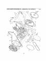
PART LiST--Model
No. 831.23943.0
Description
R0809c
Key No,
Oty,
Key No_ Qty,
Description
!
2
3
4
5
t
1
t
t
t
Frame
Upright
Rear Updght Cover
Console
Water Bottle Holder
51
52
53
54
55
I
I
I
t
t
Flywheel
tdler
C-magnet
Resistance Motor
Motor Bracket
6
7
8
9
t0
11
t2
2
t
1
t
2
2
1
Upper Body Leg
Resistance Wheel
Left Upper Body Arm
Right Upper Body Arm
Foam Grip
Upper Cap
Left Pedal
56
57
58
59
60
61
62
t
t
t
t
I
t
t
Upper Arm
Clamp
Reed Switch/Wire
Rear Shield Cover
Key
M8 Locknut
M6 x 16ram Button Screw
13
14
15
16
17
18
19
20
21
22
23
24
25
26
i
I
2
t
4
2
2
2
2
2
4
1
I
t
Right Pedal
Left Pedal Arm
Pedal Bracket
Front Upright Cover
Pivot Bushing
Disc Cover
Pivot Cover A
Front Leg Cover
Rear Leg Cover
Pivot Cover B
BUshing Set
Crank Assembly
Crank Arm
Left Pedal Disc
63
64
65
66
67
68
69
70
71
72
73
74
75
76
2
t
1
t
t
t
4
1
2
1
1
1
6
4
Shoulder Screw
Flywheel Axle
C-magnet Bolt
Idler Bolt
Key Screw
Crank Arm Screw
Resistance Motor Bolt
Rear Stabilizer
Motor Bracket Screw
Drive Belt Adjustment Screw
Front Stabilizer
M8 Locknut
M 10 x 48ram Palch Screw
M8 x 45ram Button Bolt
27
28
29
30
31
32
33
I
2
4
2
2
I
4
Right Pedal Disc
Pulse Wire
Bearing
Pedal Arm Cap
Shoulder Patch Bolt
Consoie Cover
M8 Washer
77
78
79
80
81
82
83
6
10
7
2
4
4
1
M8 ,Jam Nut
M 10 Split Washer
MIO x 20mm Patch Screw
M8 x 20ram Patch Screw
M8 x 14mm Butlon Screw
M10 x 85ram Patch Screw
M5 x 7mm Screw
34
35
36
1
t
1
Adjustment Lock
Adjustment Nut
Lower Arm
84
85
86
10
2
9
#10 x 16mm Screw
M8 x 18mm Hex Screw
M5 x 12mm Screw
37
38
39
t
2
1
Top Shield Cover
Crank Bearing
Hand]ebar
87
88
89
1
1
2
M35 x 12ram Screw
Pivot Screw
M4 x 48ram Screw
40
41
42
43
t
2
!
7
Snap Ring
Magnet
Wire Harness
M6 Washer
90
9t
92
93
1
9
2t
2
M4 x 16ram Ground Screw
M5 Star Washer
M4 x 16ram Screw
Pulse Sensor/Wire
44
45
46
t
!
I
Le[t Shield
Right Shield
Drive Belt
94
95
*
1
1
-
Flywheel Bearing
Audio Cable
User's Manual
47
48
49
50
2
2
1
2
Leveling Foot
Stabilizer Cap
Righl Peda_ Arm
Wheel
'
*
-
Assembly Tool
Grease Packet
Wire Tie
Note: Specifications are subject to change without notice For information about ordering replacement paris, see
the back cover of this manual "These parts are not illustrated, If a part is missing, call 1-888-533-1333o
21
EXPLODED
DRAWING
A--Model
*r-,*
22
No. 831.23943.0
R0809c
EXPLODED
DRAWING
B--Model
\
o")
23
No. 831.23943.0
R0809c
"
Get it fixed, at your home or ours!
Your Home
For repair--in your home--of all major brand appliances, lawn and garden equipment,
or heating and cooling systems, no matter who made It, no matter who sold Itl
For the replacement parts, accessories, and user's manuals that you need to do+it-yourself
For Sears professional instalfation of home appliances
and items _ike garage door openers and water heaters
I+8O0-4-MY-HOM E®(l+80o.46g+4ss3)
Call anytime,
www.sears,
day or night (U S A and Canada)
com
www.sears.ca
Our Home
For repair of carry+in items _ike vacuums, lawn equipment,
and electronics, call or go on-line for the location of your nearest
Sears Parts & Repair Center.
1-B00-488-t222
Call anytime, day or night (U S A only)
www.searg+,.com
To purchase a protection agreement (USA)
or maintenance agreement (Canada) on a product serviced by Sears:
1+800-827+6655 (usA)
t-800-361-6665
(Canna,)
Para pedir servicio de reparacibn a domicilio, y para ordenar piezas:
1-BB8-SU-HOGAR _ (I
.8B8-784+6427)
Sears
@ RDgEstorodTtadorca_ / TM Tradorcatk 1 s_ Service M,_rk _! Soa_s Stands, LLC
® Marca Rog_st_'_dP,/ _v M,'}rca do F&b_icrt l _ Marca do Sorvic_ do So_rs Brt,,r_s. LLC
90 DAY FULL WARRANTY
If this Sears Elliptical Exerciser iails due to a defect in material or workmanship within 90 days o! the
date of purchase, call I_00+4+MY+HOME + (t+800-469-4663) to arrange for free repair (or replacement
it repair proves impossible). There is a five year warranty on the frame
Tl_is warranty does not apply when the Elliptical Exerciser is used commercially
or for rental purposes.
This warranty gives you specific legal rights, and you may also have other rights which vary from state
to state
Sears, Roebuck and Co+,Hoffman Estates, IL 60179
J
Part No. 283920 R0809c
Printed in China © 2009 ICON IP, Inc