1
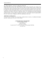
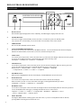
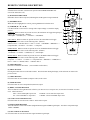
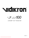
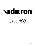
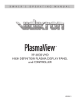
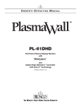
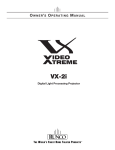
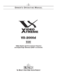
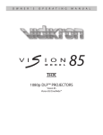
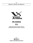
OWNER’S OPERATING MANUAL
VX-2c
Digital Light Processing Projector
and DHD Controller
TABLE OF CONTENTS
Introduction .....................................................................................................................................................
Warnings & Safety Precautions .....................................................................................................................
Limited Warranty ...........................................................................................................................................
Projector Description ......................................................................................................................................
Projector Isometric View ..............................................................................................................................
Projector Rear Panel .....................................................................................................................................
DHD Controller Description ..........................................................................................................................
Front Panel ...................................................................................................................................................
Rear Panel ....................................................................................................................................................
Remote Control ...............................................................................................................................................
Quick Setup Guide...........................................................................................................................................
Lens Shift Range .............................................................................................................................................
Example of Horizontal and Vertical Lens Shift ............................................................................................
Menu Description and Navigation .................................................................................................................
Basic Troubleshooting Tips .............................................................................................................................
RS-232 Communications .................................................................................................................................
RS-232 Commands ..........................................................................................................................................
Specifications ...................................................................................................................................................
2
3
5
7
7
7
8
8
9
10
11
14
16
17
29
30
31
33
1
INTRODUCTION
» Introduction to the Runco Video Xtreme™ VX-2c 3-Chip DLP Projector
Runco steps into the future once again with the Video Xtreme™ VX-2c projection system. The VX-2c is among the
first DLP™ projectors to offer a 16:9 native resolution, 3-chip system for home theater.
The VX-2c optical light engine utilizes three of Texas Instruments’ advanced HD-2 DMD’s™ featuring 1280 x 720
high definition resolution and 12 degree mirror tilt for the finest black level performance. Unlike previous singlechip implementations of the HD-2, no color wheel is required in a 3-chip system, reducing mechanical complexity
and compromises to color spectrum purity. The VX-2c is also Runco’s smallest 3-chip chassis ever, easily fitting
where many 3-chip projectors have not gone before, enhanced further by horizontal and vertical lens shift for
maximum installation flexibility even in the most difficult situations.
The impressive brightness inherent in 3-chip systems is further bolstered by the improved contrast capabilities of
the HD-2 chip design, offering the best of both worlds.
The VX-2c is provided with Runco’s next generation, all digital DHD Video Controller for unprecedented video
processing, scaling and aspect ratio control.
The VX-2c package represents a new level of performance and value in 3-chip projection systems and is featurefilled for both ease of operation and custom installation sophistication.
» The features you’ll enjoy include:
• Native Resolution: 1280 x 720
• 3-Chip System with 16:9 Native Aspect Ratio
• DVI Input with HDCP
• HDTV Ready
• Multiple Lens Options for Throw Distance Flexibility
• Next Generation All Digital DHD Video Controller
Contents of the package:
• 3-Chip Projection System
• (2) AC Power cords (projector/controller)
• (1) 16.5’ DVI cable
• (1) DHD remote control with (2) AAA batteries
• (1) 3mm Hex Driver
• (1) User’s manual
• (1) DHD bracket
• (1) Warranty information and registration card
Options:
• Ceiling mount unit
• Tilt mount unit
2
WARNINGS & SAFETY PRECAUTIONS
WARNING
FCC Regulations state that any unauthorized changes or modifications to this equipment not expressly approved by
the manufacturer could void the user’s authority to operate this equipment.
CAUTION: TO PREVENT FIRE OR SHOCK HAZARDS, DO NOT REMOVE COVER. DO NOT EXPOSE
THIS UNIT TO RAIN OR MOISTURE. ALSO DO NOT USE THIS UNIT’S POLARIZED PLUG WITH AN
EXTENSION CORD RECEPTACLE OR OTHER OUTLETS, UNLESS THE PRONGS CAN BE FULLY
INSERTED. REFRAIN FROM OPENING THE CABINET AS THERE ARE HIGH-VOLTAGE COMPONENTS
INSIDE. NO USER-SERVICEABLE PARTS EXCEPT LAMP UNIT. REFER SERVICING TO QUALIFIED
SERVICE PERSONNEL.
WARNING
High brightness light source. Do not stare into the beam of light, or view directly. Be especially careful that children
do not stare directly into the beam of light.
WARNING
The cooling fan in this projector continues to run for about 90 seconds after the projector is turned off. During
normal operation, when turning the power off always use the power (OFF) button on the projector or on the remote
control. Ensure the cooling fan has stopped before disconnecting the power cord. The power outlet socket should be
installed as near to the equipment as possible, and should be easily accessible.
DURING NORMAL OPERATION, NEVER TURN THE PROJECTOR OFF BY DISCONNECTING THE
POWER CORD. FAILURE TO OBSERVE THIS WILL RESULT IN PREMATURE LAMP FAILURE.
PRODUCT DISPOSAL
This projector utilizes tin-lead solder, high intensity discharge lamp (HID lamp) containing a small amount of
mercury. Disposal of these materials may be regulated due to environmental considerations. For disposal or
recycling information, please contact your local authorities or, if you are located in the United States of America,
the Electronic Industries Alliance: www.eiae.org.
INFORMATION
This equipment has been tested and found to comply with the limits for a Class B digital device, pursuant to Part
15 of the FCC Rules. These limits are designed to provide reasonable protection against harmful interference in a
residential installation. This equipment generates, uses, and can radiate radio frequency energy and, if not installed
and used in accordance with the operation manual, may cause harmful interference to radio communications.
However, there is no guarantee that interference will not occur in a particular installation. If this equipment does
cause harmful interference to radio or television reception, which can be determined by turning the equipment off
and on, the user is encouraged to try to correct the interference by one or more of the following measures:
• Reorient or relocate the receiving antenna.
• Increase the separation between the equipment and the receiver.
• Connect the equipment into an outlet on a circuit different from that to which the receiver is
connected.
• Consult the dealer or an experienced radio/TV technician for help.
3
WARNINGS & SAFETY PRECAUTIONS
DECLARATION OF CONFORMITY
RUNCO PROJECTOR, MODEL VX-2c
This device complies with Part 15 of the FCC rules. Operation is subject to the following conditions: (1) This
device may not cause harmful interference, and (2) this device must accept any interference received, including
interference that may cause undesired operation.
WARNING
Some IC chips in this product include confidential and/or trade secret property belonging to Texas Instruments.
Therefore you may not copy, modify, adapt, translate, distribute, reverse engineer, reverse assemble or discompile
the contents thereof.
INTELLECTUAL PROPERTY RIGHTS
----- IMPORTANT ----READ BEFORE USING THE PRODUCT
• Digital Light Processing, DLP, Digital Micromirror Device and DMD are trademarks of Texas Instruments.
• Microsoft and Windows are registered trademarks of Microsoft Corporation in the United States and/or other
countries.
• PC/AT is a registered trademark of International Business Machines Corporation in the United States.
• Adobe Acrobat is a trademark of Adobe Systems Incorporated.
• Macintosh is a registered trademark of Apple Computer, Inc. in the United States and/or other countries.
• All other company or product names are trademarks or registered trademarks of their respective companies.
SAFETY TIPS
Please read and follow the safety precautions listed below to ensure the equipment is free from damage, and to
ensure that no injury will occur as a result of improper use.
· Do not insert any object, especially metal or liquids, into the Projector or DHD Controller.
· Do not place any objects containing water or any other liquid on top of the Projector or DHD Controller.
· Do not place the units in direct sunlight, near heaters or in extremely dusty or humid locations.
· Do not install this system outdoors or otherwise exposed to the elements.
· Do not place heavy objects on top of the Projector or Controller.
· If the power cord is damaged or frayed in any way, electrical shock and/or fire may result. Please do not place
objects on the power cord, and keep the cord away from heat-emitting devices. Should the power cord become
damaged in any way, please contact your Runco Dealer for a replacement cord.
· Do not remove the cover of the Projector or DHD Controller for any reason. If any problems arise with the unit,
please contact a Runco Dealer or Runco International for service. Removing the covers will void the warranty.
4
LIMITED WARRANTY
Congratulations on your purchase of a Runco video product and welcome to the Runco family! We believe Runco
produces “The World’s Finest Home Theater Products”. With proper installation, setup and care, you should enjoy
many years of unparalleled video performance. Please read this consumer protection plan carefully and retain it
with your other important documents.
This is a LIMITED WARRANTY as defined by the U.S. Consumer Product Warranty and Federal Trade Commission
Improvement Act.
WHAT IS COVERED UNDER THE TERMS OF THIS WARRANTY:
SERVICE LABOR: Runco will pay for service labor by an approved Runco service center when needed as a result
of manufacturing defect for a period of two (2) years from the effective date of delivery to the end user.
PARTS (Not including projector lamp): Runco will provide new or rebuilt replacement parts for the parts that fail
due to defects in materials or workmanship for a period of two (2) years from the effective date of the warranty.
Such replacement parts are then subsequently warranted for the remaining portion (if any) of the original warranty
period.
LAMP: Six months or 1000 hours (which ever comes first).
WHAT IS NOT COVERED UNDER THE TERMS OF THIS WARRANTY:
This warranty only covers failure due to defects in materials and workmanship that occur during normal use and
does not cover normal maintenance. This warranty does not cover cabinets or any appearance item; any damage to
laser discs; failure resulting from accident, misuse, abuse, neglect, mishandling, misapplication, faulty or improper
installation or setup adjustments; improper maintenance, alteration, improper use of any input signal; damage due
to lightning or power line surges, spikes and brownouts; damage that occurs during shipping or transit; or damage
that is attributed to acts of God. In the case of remote control units, damage resulting from leaking, old, damaged or
improper batteries is also excluded from coverage under this warranty.
CAUTION:
DAMAGE RESULTING DIRECTLY OR INDIRECTLY FROM IMPROPER INSTALLATION OR SETUP IS
SPECIFICALLY EXCLUDED FROM COVERAGE UNDER THIS WARRANTY. IT IS IMPERATIVE THAT
INSTALLATION AND SETUP WORK BE PERFORMED ONLY BY AN AUTHORIZED RUNCO DEALER TO
PROTECT YOUR RIGHTS UNDER THIS WARRANTY. THIS WILL ALSO ENSURE THAT YOU ENJOY THE
FINE PERFORMANCE YOUR RUNCO PRODUCT IS CAPABLE OF PROVIDING WHEN INSTALLED AND
CALIBRATED BY RUNCO AUTHORIZED PERSONNEL.
RIGHTS, LIMITS AND EXCLUSIONS:
Runco limits its obligations under any implied warranties under state laws to a period not to exceed the warranty
period. There are no express warranties. Runco also excludes any obligation on its part for incidental or consequential
damages related to the failure of this product to function properly. Some states do not allow limitations on how long
an implied warranty lasts, and some states do not allow the exclusion or limitation of incidental or consequential
damages. So the above limitations or exclusions may not apply to you. This warranty gives you specific legal rights,
and you may also have other rights that vary from state to state.
EFFECTIVE WARRANTY DATE:
This warranty begins on the effective date of delivery to the end user. For your convenience, keep the original bill
of sale as evidence of the purchase date.
IMPORTANT: WARRANTY REGISTRATION:
Please fill out and mail your warranty registration card. It is imperative that Runco knows how to reach you promptly
if we should discover a safety problem or product update for which you must be notified.
5
LIMITED WARRANTY
TO OBTAIN SERVICE, CONTACT YOUR RUNCO DEALER:
Repairs made under the terms of the Limited Warranty covering your Runco International video product will be
performed at the location of the product, during usual working hours, providing location of product is within normal
operating distance from a Runco Authorized Service Center. If, solely in Runco’s judgement, location of product to
be repaired is beyond normal operating distance of the closest Runco Authorized Service Center, it is the owner’s
responsibility to arrange for shipment of the product for repair. These arrangements must be made through the
selling Runco dealer. If this is not possible, contact Runco directly for a return authorization number and shipping
instructions. Runco will return product transportation prepaid in the United States, unless no product defect is
discovered. In that instance, shipping costs will be the responsibility of the owner.
ADDITIONAL INFORMATION:
To locate the name and address of the nearest Runco Authorized Service location, or for additional information
about this warranty, please call, write or visit our website:
CUSTOMER SERVICE DEPARTMENT
RUNCO INTERNATIONAL
2900 Faber Street
Union City, CA 94587
Ph: (510) 324-7777 / Fax: (510) 324-9300 / Toll Free (800) 23-RUNCO
www.runco.com
6
PROJECTOR DESCRIPTION
PROJECTOR ISOMETRIC VIEW
Lens
Intake Vent
Exhaust Vent
Input Panel
PROJECTOR REAR PANEL
Vacuum
Fluorescent Display
DVI Input
Power Button and
Status LED
AC Main
Switch
Control Panel
AC Power In
7
DHD CONTROLLER DESCRIPTION
FRONT PANEL
1
8
2
3
4
5
6
7
8
9
10
1.
RUNCO ICON
When the Red light is displayed the unit is in Standby, when Blue light is displayed the unit is On.
2.
POWER BUTTON
Press once to toggle on from Standby mode to On mode, a second time to place into Standby mode.
For a discreet on or off command, you can use the direct access buttons on the remote control.
3.
IR RECEIVER
Receives the IR commands from the remote.
4.
VACUUM FLORESCENT DISPLAY
Reads out all relevant status information of the DHD at all times. Can be used instead of the On Screen Display.
Indicates the model number, current source, scan rate (resolution) and aspect ratio.
5.
UP BUTTON
Use to direct select aspect ratios or move the menu cursor Up in the On-Screen Display. When no menus are present
on-screen, the UP button will toggle you through aspect ratios in the following order:
Anamorphic → Standard (4:3) → Letterbox → VirtualWide
6.
LEFT BUTTON
Used to direct select inputs or move the menu cursor Left in the On Screen Display. When no menu is present onscreen, the LEFT button will toggle you through the different sources, in the order of:
HD Pass Thru 2 → HD Pass Thru 1 → DVI 2 → DVI 1 → HD/RGB2 → HD/RGB1
→ Component SD → S-Video 2 → S-Video 1 → Composite
7.
ENTER BUTTON
When an item is highlighted on the On-Screen Display, the ENTER button will select the item.
8.
DOWN BUTTON
Use to direct select aspect ratios or move the menu cursor Down in the On-Screen Display.
When no menu is present on-screen, this button will toggle you through the different aspect ratios.
VirtualWide → Letterbox → Standard (4:3) → Anamorphic
9.
RIGHT BUTTON
Used to direct select inputs or move the menu cursor Right in the On Screen Display.When no menus are present onscreen, the RIGHT button will toggle you through the different sources, in the order of:
Composite → S-Video 1 → S-Video 2 → Component SD → HD/RGB 1 → HD/RGB 2 → DVI 1
→ DVI 2 → HD Pass Thru 1 → HD Pass Thru 2
10.
MENU BUTTON
Pressing the MENU button will bring up the main menu. Also, if you are in an adjustment mode or function,
pressing MENU will bring the menu back one level.
DHD CONTROLLER DESCRIPTION
REAR PANEL
5
6
11
13
SYSTEM CONTROL INTERFACE
INPUTS
Serial No
Pr
R
Y
G
Pb
B
V
TRIGGERS
2
1
Y
G
CAUTION: TO REDUCE THE RISK OF ELECTRIC
SHOCK, DO NOT REMOVE COVER. NO USERSERVICEABLE PARTS INSIDE. REFER SERVICING
TO QUALIFIED SERVICE CENTER.
HD1
3
IR
Model
OUTPUTS
!
AVIS: RISQUE DE CHOC ELECTRIQUE-NE PAS OUVRIR
Runco International
Union City, CA
Pr
R
CAUTION
RISK OF ELECTRIC SHOCK
DO NOT OPEN
H
WARNING: TO REDUCE THE RISK OF FIRE
Pb
B
OR ELECTRIC SHOCK, DO NOT EXPOSE
THIS APPLIANCE TO RAIN OR MOISTURE.
HD2
Video Processor / Controller
R
Pr
G
Y
B
Pb
H
V
SDI
Pb
Pr
S-Video 1
Y
100-230VAC 50-60 Hz, 165 Watts Max
H
V
1
H/V
DVI Out
DVI 1
DVI 2
2
3
4
Option
Component Video
Video
7
8
S-Video 2 RS-232 Out
9
10
12
RS-232 Control
14
Made In USA
15
16
17
OUTPUTS:
1.
ANALOG OUTPUTS (BNC Connectors) (This output is not used when married to the VX-2c)
The various output lines used to drive the analog input of the display device. Individually, the jacks are: V=vertical
sync, H=horizontal sync, B=Blue, G=Green, R=Red. Connect these to the corresponding projector inputs.
2.
DVI OUT
The DVI digital link used to drive the digital input of an HDCP compliant display device. Connect to the projector’s
DVI inputs.
INPUTS:
3.
DVI 1 (Digital)
DVI input #1, HDCP compliant.
4.
DVI 2 (Digital)
DVI input #2, HDCP compliant.
5.
HD 1 (Analog BNC connectors)
High Definition input #1, can be RGB(HV) or
YPrPb, 480p, 720p, 480i, 576i or 1080i.
6.
HD 2 (Analog BNC connectors)
High Definition input #1, can be RGB(HV) or
YPrPb, 480p, 720p, 480i, 576i or 1080i.
7.
COMPONENT INPUT (RCA connectors)
Standard Definition (480i/576i) Component
(YPrPb) input. This is the input for component
video from sources such as DVD players. (For
best results do not run DVD player in progressive
mode).
8.
COMPOSITE INPUT (RCA connector)
This is the input for Composite Video input from
sources such as Laser disc players, VCRs and other
miscellaneous video sources.
9.
S-VIDEO 1 INPUT
This is the input for S-video #1 from sources such
as Satellite receivers, S-VHS VCR’s and DVD
players.
10.
S-VIDEO 2 INPUT
This is the input for S-video #2 from sources such
as Satellite receivers, S-VHS VCR’s and DVD
players.
11.
TRIGGERS 1/2/3 (Outputs)
Connection for 3 different 12V trigger controlled
devices.
12.
RS-232 OUT (RJ-11 Connector)
For future use.
13.
IR
Wired input from an external remote control.
14.
RS-232 CONTROL
Connection for an external RS-232 controller
device to place the DHD under system automation
control.
15.
POWER INPUT (100-230v)
Plug in main power here.
16.
MAIN FUSE
This is the main AC input fuse. (Main Fuse:
5mm x 20mm, 500mA, 250V, Slow Blow)
17.
MAIN POWER SWITCH
Disconnects or applies main power to the
processor.
9
REMOTE CONTROL DESCRIPTION
(1) ON/OFF
Switches Power ON/OFF. (This does not operate when POWER/STANDBY indicator of the main unit is off.)
1
2
(2) IR OUTPUT INDICATOR
Illuminates when a button in pressed, indicating that an IR signal is being transmitted.
(3) ENTER BUTTON
When an item is highlighted on a menu, pressing ENTER will select that item.
(4) CURSOR (▲ / ▼ / ◄ / ►)
Use these buttons to select items or settings and to adjust settings or switch the display
patterns.
UP Button: When no menus are present on-screen, the UP button will toggle through aspect
ratios in the following order: (RATIO)
Anamorphic → Standard (4:3) → Letterbox → VirtualWide
3
4
6
5
8
7
10
9
LEFT Button: When no menus are present on-screen, the LEFT button will toggle
through the different sources in the following order: (INPUT)
HD Pass Thru 2 → HD Pass Thru1 → DVI 2 → DVI 1 → HD/RGB2 → HD/RGB 1 →
Component SD → S-Video 2 → S-Video 1 → Composite
11
12
DOWN Button: When no menus are present on-screen, the RIGHT button will toggle
through the different sources in the following order: (RATIO)
VirtualWide → Letterbox → Standard (4:3) → Anamorphic
RIGHT Button: When no menus are present on-screen, the RIGHT button will toggle
through the different sources in the following order: (INPUT)
Composite → S-Video 1 → S-Video 2 → Component SD → HD/RGB 1 → HD/RGB 2 →
DVI 1 → DVI 2 → HD Pass Thru 1 → HD Pass Thru 2
(5) LIGHT BUTTON
Press this to illuminate the buttons. (*Not available on all models.)
(6) MENU BUTTON
Pressing this button will access the OSD controls. Press this button during the display of the sub-menu to return to the
previous menu.
(7) VIDEO BUTTON
Press this button to select VIDEO (composite video) as the source.
(8) COMP BUTTON
Press this button to select Component SD (480i/576i) input.
(9) DIRECT ACCESS BUTTONS
These red buttons to the right hand-side will allow you direct access to an aspect ratio, or selection of a number in certain
cases. These buttons are:
ANA - selects Anamorphic aspect ratio
LETBOX - selects Letterbox aspect ratio
4x3 - selects Standard 4:3 aspect ratio
V-WIDE - selects VirtualWide aspect ratio
(10) S-VID 1 and S-VID 2 BUTTONS
Press this button to select between S-Video 1 and S-Video 2 inputs.
(11) HD1 and HD2 BUTTONS
Press this button to select between HD1 (High Definition) signal and HD2 signal inputs. Auto detect component input,
YPbPr or RGBHV.
(12) DVI 1 and DVI 2 BUTTONS
10 Press this button to select between DVI1 signal and DVI2 signal input.
QUICK SETUP GUIDE
The VX-2c is designed to receive only digital input signals directly from the companion DHD Controller/Processor. All signal
sources should be connected to the appropriate inputs on the rear panel of the DHD. The signal from the DHD is then output
to the VX-2c projector through a Runco Proprietary (RP) DVI cable. Please note that it is NOT POSSIBLE to connect a signal
source with DVI output directly to the VX-2c. It MUST be routed through the DHD for proper operation.
DHD Controller Rear View
Runco Proprietary (RP) DVI Cable
VX-2c Projector Rear View
Follow the steps on page 16 to ensure proper installation of the VX-2c projector and DHD
Controller.
11
QUICK SETUP GUIDE
Follow the steps below ensure proper installation of the VX-2c projector and DHD Controller.
Step I
Connection:
1. Connect Power to Both Projector and DHD controller
2. Connect DVI output from the DHD to projector DVI in
3. Connect Video (Composite), S-Video to1 or 2, Component 480i (RCA) input, HD signals to HD1 or HD2 (BNC), DVI
4. Turn ON the system from the DHD controller or use the DHD remote.
Step II
From the Projector:
1. Press Menu to select Main window. Use the Up or Down arrow to select Lens Adj.
2. Adjust Lens shift, Zoom, and Focus for desired screen size.
3. Press Menu to go back to Main window and select Preference for Picture Orientation.
4. Select for projector mount configuration (Floor Front, Ceiling Front, Floor Rear, or Ceiling Rear)
Step III
Calibration and Setup:
1. Make sure you have picture on the screen from all connected sources.
Note: The system must be setup first by using S-Video or Component 480i (RCA input) preferably Component 480i
first.
2. Select Component SD from the DHD controller.
3. Using a test disc and select the Pluge pattern for Brightness and 10-step gray scale for Contrast
4. From the DHD controller, select Calibration, press Enter and under ISF Night select Input Image.
5. Adjust for correct Brightness and Contrast.
6. Select 80 IRE from test disc.
Go to projector.
7. Press Menu to select Main window. From Main window select Image and press Enter.
8. Select Contrast and press Enter.
Under Contrast you have Red, Green, and Blue selection.
9. Use the Up and Down arrow to select Green or Blue and press Enter. The cursor will blink from the selected color. Use
the UP or Down arrow to adjust. Pres Enter when done to store the number.
Note: Decrease the value to set for desired temperature.
10. Select 20 or 30 IRE window for low-end adjustment
11. Select Brightness and adjust RED, Green, or Blue for D6500. Note: Decrease the value to set for D6500.
12. Select color bar from test disc.
13. From the DHD controller select Calibration, press Enter and under ISF Night select Input Image and select Color and
press Enter
14. Use the Blue Filter (required) and adjust for correct color setting.
* From this point on, the Projector should not be touched and all other adjustments for other sources must be done
at the DHD Controller.
15. For other NTSC sources, select Calibration, press Enter. Under ISF Night, select Input Image and adjust for correct
Brightness, Contrast, Color, Tint, and sharpness.
Step IV
HD and DVI Setup:
From DHD controller
1. For HD input and DVI, select Calibration press Enter and under ISF Night select Input Image for video adjustments.
2. Select Input Color for white balance adjustments.
12
QUICK SETUP GUIDE
While there are many different ways to connect your source equipment to your DHD Controller, the examples below are the
most common.
ANALOG INPUTS:
• Composite Video Input
Composite video is the most common type of signal used, but is also the lowest in picture quality. Many sources have outputs
that are limited to composite video, such as some VCR’s and camcorders; others such as Laser Disc players actually produce
slightly better results when using composite video.
• S-Video Input
S-video is the second-best type of signal that can be used, but is MUCH better than composite video. Using such sources as
Satellite receivers, high-quality VCRs and DVD players (with no component output) will produce a MUCH cleaner and sharper
signal.
• Component Input
Component video is the best type of signal that can be used. The most common sources that use component outputs are DVD
players, and it is highly recommended that component be used when possible. Component video goes one step beyond S-video
in picture quality; chroma (color) information is more resolved and the overall picture appears more well-defined. (be sure to
shut off progressive scan on your DVD player)
• HD1 / HD2
These are High Definition Analog inputs to connect the outputs of high definition sources such as HD tuners and set top boxes,
HD satellite receivers, etc. These inputs will accept signals as RGB, RGBHV or Component Video (YPrPb).
DIGITAL INPUTS:
• DVI 1 / DVI 2
These are High Definition Digital inputs. Runco recommends using these digital inputs whenever possible. Using the DVI 1
and DVI 2 inputs ensures the highest video quality because the signal is carried in the digital domain throughout the entire
signal path, from source component output, through the DHD and finally into the projector. This maintains maximum signal
purity.
Use these inputs to connect Digital High Definition sources that have a DVI output, such as HD tuners and set top boxes,
satellite receivers, DVD players, etc.
ISF Calibration
The VX-2c/DHD system has been designed to incorporate setup and calibration standards established by the Imaging Science
Foundation (ISF). The ISF has developed carefully crafted, industry-recognized standards for optimal video performance and
has implemented a training program for technicians and installers to use these standards to obtain optimal picture quality from
Runco video display devices. Accordingly, Runco recommends that setup and calibration be performed by an ISF certified
installation technician.
All signal types require separate processing. Therefore there is a need to calibrate each and every input separately.
When beginning calibration of the DHD, it is imperative that at least one of the analog SD inputs (Composite, S-Video, RCA
Component) be calibrated first. In doing this, the projector is calibrated to the controller. After one of the SD inputs is calibrated,
calibration of the HD analog or DVI sections can follow.
Once the initial settings have been completed, the “front panel display” (color, tint, sharpness, etc.) can be adjusted for each
aspect ratio. The calibration procedures for these adjustments are outlined in “picture quality adjustments”.
13
LENS SHIFT RANGE
Lens Option 1: Throw Distance 1.2 - 1.4 x Width of Screen
When only Vertical or only Horizontal Shift is used:
Maximum. Vertical Shift ↑ = 60% of screen height (.60 x height)
Maximum. Vertical Shift ↓ = 24% of screen height (.24 x height)
Maximum Horizontal Shift = 10% of screen width (.10 x width)
Amount of Horizontal Shift when Vertical is @ maximum:
Maximum Horizontal Shift < 5% of screen width (.05 x width)
Amount of Vertical Shift when Horizontal is @ maximum:
Maximum Vertical Shift ↑ < 10% of screen height (.10 x height)
Maximum Vertical Shift ↓ < 10% of screen height (.10 x height)
Lens Option 2: Throw Distance 1.4 - 1.77 x Width of Screen
When only Vertical or only Horizontal Shift is used:
Maximum. Vertical Shift ↑ = 60% of screen height (.60 x height)
Maximum. Vertical Shift ↓ = 24% of screen height (.24 x height)
Maximum Horizontal Shift = 13% of screen width (.13 x width)
Amount of Horizontal Shift when Vertical is @ maximum:
Maximum Horizontal Shift < 5% of screen width (.05 x width)
Amount of Vertical Shift when Horizontal is @ maximum:
Maximum Vertical Shift ↑ < 10% of screen height (.10 x height)
Maximum Vertical Shift ↓ < 10% of screen height (.10 x height)
Lens Option 3: Throw Distance 1.77 - 2.35 x Width of Screen
When only Vertical or only Horizontal Shift is used:
Maximum. Vertical Shift ↑ = 60% of screen height (.60 x height)
Maximum. Vertical Shift ↓ = 24% of screen height (.24 x height)
Maximum Horizontal Shift = 16% of screen width (.16 x width)
Amount of Horizontal Shift when Vertical is @ maximum:
Maximum Horizontal Shift < 5% of screen width (.05 x width)
Amount of Vertical Shift when Horizontal is @ maximum:
Maximum Vertical Shift ↑ < 10% of screen height (.10 x height)
Maximum Vertical Shift ↓ < 10% of screen height (.10 x height)
Explanation:
•
•
•
•
•
•
14
Example: 56” x 100” Screen
TD = 120” to 140” lens to screen
0.24 X 56” = 13.44” up or down
0.10 X 100” = 10.0” left or right
0.05 X 100” = 5.0” left or right
0.10 X 56” = 5.6” up or down
Example: 56” x 100” Screen
TD = 140” to 177” lens to screen
0.24 X 56” = 13.44” up or down
0.13 X 100” = 13.0” left or right
0.05 X 100” = 5.0” left or right
0.10 X 56” = 5.6” up or down
Example: 56” x 100” Screen
TD = 177” to 235” lens to screen
0.24 X 56” = 13.44” up or down
0.16 X 100” = 16.0” left or right
0.05 X 100” = 5.0” left or right
0.10 X 56” = 5.6” up or down
0% shift is when the image center is even with the projector lens center. (Also known as zero-degree projection-angle)
Shifting beyond the maximum values above will cause image loss in corners or edges.
When Vertical Shift is maximum, Horizontal shift can only be adjusted 5% left or right in example above.
The maximum diagonal movement of the image is expressed as shift in 2 directions, this is the maximum combination of adjustment.
(ex. Up & Left, Down & Right, Up & Right, Down & Left)
Throw distance does not affect image quality.
Lens shift does not affect image quality if within above limits.
LENS SHIFT RANGE
Lens Option 4: Throw Distance 2.35 - 3.60 x Width of Screen
When only Vertical or only Horizontal Shift is used:
Maximum. Vertical Shift ↑ = 60% of screen height (.60 x height)
Maximum. Vertical Shift ↓ = 24% of screen height (.24 x height)
Maximum Horizontal Shift = 16% of screen width (.16 x width)
Amount of Horizontal Shift when Vertical is @ maximum:
Maximum Horizontal Shift < 5% of screen width (.05 x width)
Amount of Vertical Shift when Horizontal is @ maximum:
Maximum Vertical Shift ↑ < 10% of screen height (.10 x height)
Maximum Vertical Shift ↓ < 10% of screen height (.10 x height)
Lens Option 5: Throw Distance 3.60 - 5.70 x Width of Screen
When only Vertical or only Horizontal Shift is used:
Maximum. Vertical Shift ↑ = 60% of screen height (.60 x height)
Maximum. Vertical Shift ↓ = 24% of screen height (.24 x height)
Maximum Horizontal Shift = 16% of screen width (.16 x width)
Amount of Horizontal Shift when Vertical is @ maximum:
Maximum Horizontal Shift < 5% of screen width (.05 x width)
Amount of Vertical Shift when Horizontal is @ maximum:
Maximum Vertical Shift ↑ < 10% of screen height (.10 x height)
Maximum Vertical Shift ↓ < 10% of screen height (.10 x height)
Lens Option 6: Throw Distance 0.67 Fixed x Width of Screen
Example: 56” x 100” Screen
TD = 235” to 360” lens to screen
0.24 X 56” = 13.44” up or down
0.16 X 100” = 16.0” left or right
0.05 X 100” = 5.0” left or right
0.10 X 56” = 5.6” up or down
Example: 56” x 100” Screen
TD = 360” to 570” lens to screen
0.24 X 56” = 13.44” up or down
0.16 X 100” = 16.0” left or right
0.05 X 100” = 5.0” left or right
0.10 X 56” = 5.6” up or down
For rear screen installations.
Contact Runco Technical Support
Explanation:
•
•
•
•
•
•
0% shift is when the image center is even with the projector lens center. (Also known as zero-degree projection-angle)
Shifting beyond the maximum values above will cause image loss in corners or edges.
When Vertical Shift is maximum, Horizontal shift can only be adjusted 5% left or right in example above.
The maximum diagonal movement of the image is expressed as shift in 2 directions, this is the maximum combination of adjustment.
(ex. Up & Left, Down & Right, Up & Right, Down & Left)
Throw distance does not affect image quality.
Lens shift does not affect image quality if within above limits.
15
LENS SHIFT RANGE
Example of Horizontal and Vertical Lens Shift
VERTICAL LENS SHIFT (UP OR DOWN)
Note: This is a general example
of Vertical Lens Shift. Each lens
type will vary. No particular lens
was used in this example.
�����������
����������
���������
�����������
����������
���������
����������
�����������
���������
�������������
��
����������������������������
�����������������������������
���������������������
HORIZONTAL LENS SHIFT (LEFT OR RIGHT)
���������������������
���������
���������������������
���������
���������������������
���������
�������������
��
����������������
Note: This is a general example
of Horizontal Lens Shift. Each
lens type will vary. No particular
lens was used in this example.
16
MENU DESCRIPTION AND NAVIGATION
» PROJECTOR CONTROL
Once the VX-2c and DHD controller have been properly installed and connected, you are ready to perform set-up and
calibration procedures. All setup and calibration parameters are accessed and adjusted through the VX-2c fluorescent display
menu system.
The VX-2c/DHD system has been designed to incorporate setup and calibration standards established by the Imaging Science
Foundation (ISF). The ISF has developed carefully crafted , industry-recognized standards for optimal video performance and
has implemented a training program for technicians and installers to use these standards to obtain optimal picture quality from
Runco video display devices.
Accordingly, Runco recommends that setup and calibration be performed by an ISF certified installation technician.
The VX-2c menu system is organized to provide for a logical, step by step approach to both setup and operation.
To begin, press the “Menu” button on the rear panel of the VX-2c. This will bring up the fluorescent display menu and you
may then proceed as follows:
Default
Red
Green
Blue
Offset
Red
Green
Blue
Gain
Offset
Gamma
Wt. Balance
Gamma
Red
Green
Blue
Orient
Lens Adj.
MAIN MENU
Proj. Info
Advanced
Orient
Shift L/R
Shift U/D
Lens Zoom
Lens Focus
Floor F.
Ceiling F.
Floor R.
Ceiling R.
Model
S/N
Hardware Revision
Firmware Revision
Error Code
Diagnose
Lamp
Color
Service
Reset to Default
Red
Green
Blue
Yellow
Cyan
Magenta
Normal
Color Enable
Tests
Lamp Hours
Lamp S/N
Change Lamp
Gamut
Color Space
Color Temp
Power Cycle
Standby Time
No. of Lamps Used
Color Bar 75 IRE
Color Bar 100 IRE
External H Ramp
Test Black
Test White
Test Green
Test Red
Test Blue
Check Board
Alignment
H Ramp
V Ramp
Manual
HD
SD NTSC
SD PAL
5000K
6500K
9300K
White
Red
Green
Blue
17
MENU DESCRIPTION AND NAVIGATION
MAIN MENU
MAIN MENU
Main Menu
Wt. Balance
Orient
Lens Adj.
Proj. Info
Advanced
Wt. Balance
Orient
Opening screen
Press ENTER to access the White Balance Settings menu
Press ENTER to access the Orientation Setting menu
Lens Adj.
Proj. Info
Advanced
Press ENTER to access the Lens Adjustment setting menu
Press ENTER to access the Projector Status menu
Press ENTER to access the Advanced Settings menu
This is the first menu that will appear when “MENU” is selected. The above diagram depicts the main menu.
There are five option items in the Main menu:
Wt. Balance: Adjusting Contrast, Brightness, and Gamma
Orient: Adjusting Picture Orientation (FF, CF, RF, and CR)
Lens Adj. : Adjusting Lens shift, Lens Zoom, and Lens Focus.
Proj. Info: Checking the projector status
Advanced: This window is used for optimization and service info.
When the MENU button is pressed the following will be displayed on the Vacuum Florescent Display.
Arrows indicates highlighted option to be selected:
MAIN:
Wt. Balance►
←
Orient ►
Main menu is
currently selected.
Selectable options in main menu.
Note: Due to limitation of the display, only two options can be displayed at a time
* Press the MENU key to call up the MAIN window.
* Use the UP or DOWN button to move to your selection.
* Press the ENTER button to activate your selection.
* Press MENU to exit.
Note: Due to limitation of the display, only two options can be displayed at a time.
Wt. Balance
Gain
Offset
Gamma
Wt. Balance
Gain
Offset
Gamma
Indicates you are on the Image Settings menu
Press ENTER to access the Contrast Setting menu
Press ENTER to access the Brightness Setting menu
Press ENTER to access the Gamma Setting menu
From the Main menu use the Up or Down arrow to select “Wt. Balance” and press the Enter button to call up the
Wt. Balance options.
There are three options Gain, Offset, Brightness, and Gamma.
Use the Up or Down button to indication your selection and press the Enter button to make your selection.
Each selection has separate adjustment for Red, Green , and Blue.
Press the Enter button on selected item. A cursor will blink, use the up or down arrow keys to make your adjustment.
Press Enter to store the change.
18 Press the Menu button to exit.
MENU DESCRIPTION AND NAVIGATION
Orient
Orient
Preference
Orient
Indicates you are on the Preference Settings menu
Press ENTER to select the Orientation setting menu
Use Preference window to select projector picture orientation
From the Main menu use the Up or Down arrow to select “Orient” and press the Enter button to call up the Orient
display. The Orient display allows selection of Picture Orientation options.
There are four options:
Floor F.: Floor Front configuration.
Ceiling F.: Ceiling Front configuration
Floor R.: Floor Rear configuration
Ceiling R.: Ceiling Rear configuration
Use the Up or Down button to indication your selection and press the Enter button to make your selection.
Press the Menu button to exit.
Lens Adj.
Shift L/R
Shift U/D
Lens Zoom
Lens Focus
Lens Adj.
Shift L/R
Shift U/D
Lens Zoom
Lens Focus
Indicates you are on the Lens setting menu
Press ENTER to Shift the lens Left and Right by using the
Left and Right arrows
Press ENTER to Shift the lens Up and Down by using the Up
and Down arrows
Press ENTER to Focus the lens by using the Up and Down
arrows
Press ENTER to Zoom the lens by using the Up and Down
arrows
Use the Lens Adj. display to make lens adjustments
From the Main menu use the Up or Down arrow to select “Lens Adj.” and press the Enter button to call up the
Lens Adj. Options.
There are four options:
Shift L/R: Shift the image (mechanically) left or right.
Shift U/D: Shift the image (mechanically) up or down.
Lens Zoom: Decrease or Enlarge the image size (mechanically).
Lens Focus: Adjusting the image focus.
Use the Up or Down button to indication your selection and press the Enter button to make your selection.
Press the Menu button to exit.
19
MENU DESCRIPTION AND NAVIGATION
Proj. Info
Model
S/N
Hardware Revision
Firmware Revision
Error Code
Proj. Info
Model
S/N
Hardware
Revision
Firmware
Revision
Error Code
Indicates you are on the Status reading menu
Reports the Projector Model
Reports the Projector Serial Number
Reports the Projector Hardware Revision number
Reports the Projector Firmware Revision number
Reports the last Projector Error Code received
From the Main menu use the Up or Down arrow to select “Proj. Info” and press the Enter button to call up the
Status options.
There are five options:
Model: VX-2c should be displayed.
S/N: Projector serial number identification.
Hardware Rev.: Projector hardware revision.
Firmware Rev.: Current firmware revision.
Error Code: System error code
Use the Up or Down button to indication your selection and press the Enter button to make your selection.
Press the Menu button to exit.
Advanced
Diagnose
Lamp
Color
Reset to Default
Service
Under Advanced there are five sub-windows
Advanced
Diagnose
Lamp
Color
Reset to Default
Service
Indicates you are on the Advanced Settings menu
Press ENTER to access the Diagnostics menu
Press ENTER to access the Lamp Settings menu
Press ENTER to access the Color Settings menu
Press ENTER to set the Presets back to their Factory Default
settings and then confirm YES or NO with the arrows and
ENTER key
Press ENTER to access the Service Functions Menu
From the Main menu use the Up or Down arrow to select “Advanced” and press the Enter button to call up the
Advanced options.
Use the Up or Down button to indication your selection and press the Enter button to make your selection.
Press the Menu button to exit.
20
MENU DESCRIPTION AND NAVIGATION
OPERATIONAL INSTRUCTIONS
Gain
Red
Green
Blue
Gain
Red
Green
Blue
Indicates you are in the Contrast Setting Menu
Press ENTER to change the Red Contrast setting by using the
UP and DOWN arrows to Increase or Decrease the value
Press ENTER to change the Green Contrast setting by using
the UP and DOWN arrows to Increase or Decrease the value
Press ENTER to change the Blue Contrast setting by using the
UP and DOWN arrows to Increase or Decrease the value
From the Image menu use the Up or Down arrow to select “Contrast” and press the Enter button to call up the
Contrast options.
Use the Up or Down button to indication your selection and press the Enter button to make your selection.
Press the Menu button to exit.
Brightness
Red
Green
Blue
Brightness
Red
Green
Blue
Indicates you are in the Brightness Setting Menu
Press ENTER to change the Red Brightness setting by using
the UP and DOWN arrows to Increase or Decrease the value
Press ENTER to change the Green Brightness setting by using
the UP and DOWN arrows to Increase or Decrease the value
Press ENTER to change the Blue Brightness setting by using
the UP and DOWN arrows to Increase or Decrease the value
From the Image menu use the Up or Down arrow to select “Brightness” and press the Enter button to call up the
Brightness options.
Use the Up or Down button to indication your selection and press the Enter button to make your selection.
Press the Menu button to exit.
21
MENU DESCRIPTION AND NAVIGATION
Gamma
Red
Green
Blue
Gamma
Red
Green
Blue
Indicates you are in the Gamma Setting Menu
Press ENTER to change the Red Gamma setting by using the
UP and DOWN arrows to Increase or Decrease the value
Press ENTER to change the Green Gamma setting by using
the UP and DOWN arrows to Increase or Decrease the value
Press ENTER to change the Blue Gamma setting by using the
UP and DOWN arrows to Increase or Decrease the value
From the Image menu use the Up or Down arrow to select “Gamma” and press the Enter button to call up the
Gamma options.
Use the Up or Down button to indication your selection and press the Enter button to make your selection.
Press the Menu button to exit.
Orientation
Floor F.
Ceiling F.
Floor R.
Ceiling R.
Orientation
Floor F.
Ceiling F.
Floor R.
Ceiling R.
Indicates you are in the Projector Orientation Setting menu
Press ENTER to Set the projector to Front Projection mode
Press ENTER to Set the projector to Inverted Front Projection
mode
Press ENTER to Set the projector to Rear Projection mode
Press ENTER to Set the projector to Inverted Rear Projection
mode
From the Preference menu use the Up or Down arrow to select “Orientation” and press the Enter button to call
up the Orientation options.
Use the Up or Down button to indication your selection and press the Enter button to make your selection.
Press the Menu button to exit.
22
MENU DESCRIPTION AND NAVIGATION
Diagnose
Normal
Color Enable
Tests
Diagnose
Normal
Color Enable
Tests
Indicates you are in the Diagnostics menu
Press ENTER to return all Diagnostic Tests to their Normal
mode
Press ENTER to individually Enable each Color
Press ENTER to access External front end board and Internal
DLP Test Modes
From the Advanced menu use the Up or Down arrow to select “Diagnose” and press the Enter button to call up
the Diagnose options.
There are three options:
Normal: Return to normal video viewing
Color Enable: Red, Green, Blue, Yellow, Cyan, Magenta from the active video
Tests: Color Bar 75 IRE, Color Bar 100 IRE, External H Ramp, Test Black, Test White, Test Green, Test
Red, Test Blue, Check Board, Alignment, H Ramp and V Ramp
Use the Up or Down button to indication your selection and press the Enter button to make your selection.
Press the Menu button to exit.
Lamp
Lamp Hours
Lamp S/N
Change Lamp
Lamp
Lamp Hours
Lamp S/N
Change Lamp
Indicates you are in the Lamp Settings menu
Press ENTER to return the accumulated lamp operation hours
Press ENTER to return the Lamp Serial Number
Press ENTER to indicate that the lamp has been changed and
the hours counter is to be reset to zero
From the Advanced menu use the Up or Down arrow to select “Lamp” and press the Enter button to call up the
Lamp options.
Use the Up or Down button to indication your selection and press the Enter button to make your selection.
Press the Menu button to exit.
23
MENU DESCRIPTION AND NAVIGATION
Color
Gamut
Color Space
Color Temp
Color
Gamut
Color Space
Color Temp
Indicates you are in the Color Settings menu
Press ENTER to access the Gamut settings menu
Press ENTER to access the Color Space settings menu
Press ENTER to access the Color Temperature setting menu
From the Advanced menu use the Up or Down arrow to select “Color” and press the Enter button to call up the
Color options.
There are three options:
Gamut: Manual, projector white balance calibration for D6500K
Color Space: Hi-Def, SD NTSC, SD PAL
Color Temp: 5000K, 6500K, 9300K
Use the Up or Down button to indication your selection and press the Enter button to make your selection.
Press the Menu button to exit.
Reset to Default
Service
Power Cycle
Standby Time
No. of Lamps Used
Reset to Default
This display will Reset all of the projector settings back to the
original factory default.
Service
Indicates you are in the Service Information menu
Power Cycle
Press Enter to return the number of Power Cycles the unit has
undergone
Standby time
Press Enter to return the amount of Standby Time the unit has
undergone
No. of lamps used Press Enter to return the number of Lamp Changes the unit
has undergone
From the Advanced menu use the Up or Down arrow to select “Service” and press the Enter button to call up the
Service options.
Use the Up or Down button to indication your selection and press the Enter button to make your selection.
Press the Menu button to exit.
24
MENU DESCRIPTION AND NAVIGATION
Color Enable
Red
Green
Blue
Yellow
Cyan
Magenta
Color Enable
Red
Green
Blue
Yellow
Cyan
Magenta
Indicates you are in the Color Enable menu
Press ENTER to turn Red On
Press ENTER to turn Green On
Press ENTER to turn Blue On
Press ENTER to turn Red Off
Press ENTER to turn Blue Off
Press ENTER to turn Green Off
From the Diagnose menu use the Up or Down arrow to select “Color Enable” and press the Enter button to call
up the Service options.
Use the Up or Down button to indication your selection and press the Enter button to make your selection.
Press the Menu button to exit.
Ext Test
Color Bar 75 IRE
Color Bar 100 IRE
External H Ramp
Ext Test
Color Bar 75 IRE
Color Bar 100 IRE
External H Ramp
Indicates you are In the External front end board Test mode
Press ENTER to display the high brightness color bars
Press ENTER to display the low brightness color bars
Press ENTER to display the External Horizontal Ramp test
image
From the Diagnose menu use the Up or Down arrow to select “Ext Test” and press the Enter button to call up the
Service options.
Use the Up or Down button to indication your selection and press the Enter button to make your selection.
Press the Menu button to exit.
25
MENU DESCRIPTION AND NAVIGATION
Tests
Test Black
Test White
Test Green
Test Red
Test Blue
Check Board
Alignment
H Ramp
V Ramp
Tests
Indicates you are In the Internal DLP Test mode
Test Black
Test White
Test Green
Test Red
Test Blue
Check Board
Alignment
H ramp
V ramp
Press ENTER to display a full Black screen
Press ENTER to display a full White screen
Press ENTER to display a full Green screen
Press ENTER to display a full Red screen
Press ENTER to display a full Blue screen
Press ENTER to display a Checker Board pattern
Press ENTER to display an Alignment crosshatch pattern
Press ENTER to display a Horizontal Grey Ramp
Press ENTER to display a Vertical Grey Ramp
From the Diagnose menu use the Up or Down arrow to select “Int Test” and press the Enter button to call up the Service
options.
Use the Up or Down button to indication your selection and press the Enter button to make your selection.
Press the Menu button to exit.
Gamut
Manual
Gamut
Manual
Indicates you are in the Gamut Settings menu
Puts Gamut setting into Manual mode
From the Color menu use the Up or Down arrow to select “Gamut” and press the Enter button to call up the Manual option.
Use the Up or Down button to indication your selection and press the Enter button to make your selection.
Press the Menu button to exit.
26
MENU DESCRIPTION AND NAVIGATION
Color Space
HD
SD NTSC
SD PAL
Color Space
HD
SD NTSC
SD PAL
Indicates you are in the Color Space setting menu
Press ENTER to select the HD Color Space
Press ENTER to select the SD NTSC Color Space
Press ENTER to select the SD PAL Color Space
From the Color menu use the Up or Down arrow to select “Color Space” and press the Enter button to call up the
Service options.
Use the Up or Down button to indication your selection and press the Enter button to make your selection.
Press the Menu button to exit.
Color Temp
5000K
6500K
9300K
Color Temp
5000K
6500K
9300K
Indicates you are in the Color Temperature setting menu
Press ENTER to select a 5000K Color Temperature
Press ENTER to select a 6500K Color Temperature
Press ENTER to select a 9300K Color Temperature
From the Color menu use the Up or Down arrow to select “Color Temp” and press the Enter button to call up the
Service options.
Use the Up or Down button to indication your selection and press the Enter button to make your selection.
Press the Menu button to exit.
27
MENU DESCRIPTION AND NAVIGATION
Manual
White
Red
Green
Blue
Manual
White X=0.XXX
White Y=0.YYY
Red X=0.XXX
Red Y=0.YYY
Green X=0.XXX
Green Y=0.YYY
Blue X=0.XXX
Blue Y=0.YYY
Indicates you are in the Manual Gamut setting mode using a
calibrated colorimeter. Note that changes are not made till
you EXIT this menu
Press ENTER to change the White X value using the Left
and Right arrows to select the digit to change and the Up and
Down arrows to change, then ENTER to effect
Press ENTER to change the White Y value using the Left
and Right arrows to select the digit to change and the Up and
Down arrows to change, then ENTER to effect
Press ENTER to change the Red X value using the Left and
Right arrows to select the digit to change and the Up and
Down arrows to change, then ENTER to effect
Press ENTER to change the Red Y value using the Left and
Right arrows to select the digit to change and the Up and
Down arrows to change, then ENTER to effect
Press ENTER to change the Green X value using the Left
and Right arrows to select the digit to change and the Up and
Down arrows to change, then ENTER to effect
Press ENTER to change the Green Y value using the Left
and Right arrows to select the digit to change and the Up and
Down arrows to change, then ENTER to effect
Press ENTER to change the Blue X value using the Left and
Right arrows to select the digit to change and the Up and
Down arrows to change, then ENTER to effect
Press ENTER to change the Blue Y value using the Left and
Right arrows to select the digit to change and the Up and
Down arrows to change, then ENTER to effect
COLOR SPACE COORDINATES FOR REFERENCE
GAMUT
X
Y
EBU red
0.64
0.33
EBU green
0.29
EBU blue
GAMUT
X
Y
NTSC red
0.67
0.33
0.6
NTSC green
0.21
0.71
0.15
0.06
NTSC blue
0.14
0.08
SMPTE C red
0.635
0.340
Graphics red
0.628
0.346
SMPTE C green
0.305
0.595
Graphics green
0.268
0.588
SMPTE C blue
0.155
0.070
Graphics blue
0.15
0.07
Procedure:
1. Set up PR or Milori color meter
2. Enter manual Gamut setting menu
3. Measure X and Y values of White
4. Enter measured values by scrolling to the digit to be changed, use the up and down keys to change it and then moving
to the next digit. Hit ENTER to save the numbers.
5. Repeat the above procedure with the red, green and blue values exit the Gamut setting menu all the way back to
NORMAL to establish the changes
28
BASIC TROUBLESHOOTING TIPS
The following is a basic troubleshooting guide that can assist you in resolving typical problems may result in normal
operation. If you have encountered problems that are not listed in this guide, please contact your Runco dealer for assistance.
PROBLEM
POSSIBLE CAUSE
SOLUTION
The Projector does not turn on after
initial installation. The Power LED on
the front of the Controller stays red
after the power button is pressed.
· The DVI cable is not connected
between the Controller and Projector,
or is connected improperly.
· The projector is not plugged in, or
its AC outlet is not active. Look at its
power LED and see if it is illuminated.
· Ensure it is firmly plugged into both
the Controller and the Projector.
· Verify that the AC outlet is active, or
that the Projector is plugged in.
The Projector and Controller are both
on, but there is no video image onscreen.
· The Controller is on the wrong source. · Press MENU on the Projector’s
· The Controller is on the correct
remote, and look to see which source is
source, but the source itself is off.
active (the arrow will be pointing to the
active source). Select the correct source
as appropriate.
· Turn on the source. It is recommended
that all sources be turned on first
BEFORE the VX-2c.
· A progressive scan DVD is plugged
· Only NTSC/PAL can be input to the
into Component input rather than the
Component input. Progressive scan
RGB/Component input.
must go into RGB/Component.
The Projector is producing a ‘split
screen’ or an otherwise scrambled
image.
The image appears too bright, and there · Contrast is set too high.
is a loss of definition in the brightest
· The DVD player is set for a high-level
areas of the image.
output.
· The video signal has not been
terminated properly somewhere in the
system.
· Turn down the CONTRAST level on
the Controller.
· Set the DVD player for a nominal
output (no boost or gain).
· Ensure all video signals are
terminated in 75 Ohms.
The image appears too ‘washed out’, or · Brightness is set too high.
the darkest areas of the image appear
· The DVD player may be set for too
too bright.
high of a brightness level.
· Turn down the BRIGHTNESS level
on the Controller. If possible, use a
PLUGE pattern to set the brightness
level properly.
· Set the DVD player for a nominal
output (no boost or gain).
The colors of the image appear
abnormal
· The Red, Green and/or Blue outputs
of the Controller or inputs to the
Projector are reversed.
· The Pr and Pb inputs on the
Component input on the Controller are
reversed
· Check the cable connections on
the back of the Controller or on the
Projector.
The Projector will not turn back on
after it was powered-down, or the
image disappears during operation.
· The Projector will not turn on for two
minutes after power-down to protect its
bulb.
· The bulb has failed
· Wait two minutes until the LED on the
front of the Controller turns red.
29
RS-232 COMMUNICATIONS
Baud rate: 19200 (fixed)
Bits: 8
No Parity
All protocol in ASCII format
RS-232 input connector pin numbers:
TxD= Pin# 2, RxD= Pin# 3, GnD= Pin# 5
Command format (single command): command value (i.e. brightness 100).
NOTE: A space (not an underscore) or comma may be used between the command and its value.
Command string format: command, command value, command etc.
(i.e. COMPOSITE, BRIGHTNESS 100, ANAMORPHIC, <CR>)
NOTE: In between commands, a comma or space may be used
NOTE: A carriage return must be used after each command or string.
Other notes:
• For command strings, a maximum of 255 characters can be used in a single string.
• PARAMETER min/max refers to a function’s minimum and maximum value range.
Inputting values above or below their range may cause unpredictable (but not fatal) results.
30
RS-232 COMMANDS
Command
Parameter
(min/max)
Value Stored?
Description
POWER
ON
OFF
COMPOSITE
SVIDEO1
SVIDEO2
COMPONENT
HD1
HD2
DVI1
DVI2
HD1Pass
HD2Pass
OUT43
OUT169
ANAMORPHIC
STANDARD
LETTERBOX
VIRTUALWIDE
RGBNN
RGBPP
RGBS
YUV
IHPOS
IVPOS
IWIDTH
IHEIGHT
OVERSCAN
OHPOS
OVPOS
OWIDTH
OHEIGHT
BRIGHTNESS
CONTRAST
COLOR
TINT
SHARPNESS
NIGHT
DAY
CUSTOM1
CUSTOM2
TRIGGER
BKGND
0/1
NA
NA
NA
NA
NA
NA
NA
NA
NA
NA
NA
NA
NA
NA
NA
NA
NA
NA
NA
NA
NA
NA
-100/100
-100/100
-100/100
-100/100
0/10
-100/100
-100/100
-100/100
-100/100
-100/100
-100/100
-100/100
-100/100
-6/6
NA
NA
NA
NA
1/3
-100/-100
NA
NA
NA
YES
YES
YES
YES
YES
YES
YES
YES
YES
YES
YES
YES
YES
YES
YES
YES
YES
YES
YES
YES
YES
YES
YES
YES
YES
YES
YES
YES
YES
YES
YES
YES
YES
YES
YES
YES
YES
YES
YES
YES
Turns DHD On and Off
Turns DHD Controller on
Turns DHD Controller off
Selects the Composite video input
Selects the S-Video 1 input
Selects the S-Video 2 input
Selects the Component input
Selects the RGB HD 1 input
Selects the RGB HD 2 input
Selects the DVI 1 input
Selects the DVI 2 input
Selects the HD 1 Pass Thru input
Selects the HD 2 Pass Thru input
Selects the output screen
Selects the output screen
Selects the anamorphic aspect ratio
Selects the standard (4:3) aspect ratio
Selects the letterbox aspect ratio
Selects the VirtualWide aspect ratio
Outputs color space RGB w/negative, negative sync
Outputs color space RGB w/positive, positive sync
Outputs color space RGB w/embedded sync on green
HD YUV output color space
Sets a value for horizontal position input
Sets a value for vertical position input
Sets the value for width input
Sets the value for height input
Sets the overscan value in %
Sets the value for width output
Sets the value for height output
Sets the value for width output
Sets the value for height output
Sets a value for brightness
Sets a value for contrast
Sets a value for color
Sets a value for tint
Sets a value for sharpness
Selects the ISF Night setting
Selects the ISF Day setting
Sets the value per client
Sets the value per client
Sets the trigger
Sets the background color for letterbox
31
RS-232 COMMANDS
32
Command
Parameter
(min/max)
Value Stored?
Description
IHPOS?
IHEIGHT?
OHPOS?
OHEIGHT?
COLOR?
ASPECT?
INPUT?
OUTRES?
SERIALNUM?
DATE?
IVPOS?
OVERSCAN?
OVPOS?
BRIGHTNESS?
TINT?
PRESET?
POWER?
ASPECTIN?
SWVER?
IWIDTH?
PHASE?
OWIDTH?
CONTRAST?
SHARPNESS?
BKGND?
INRES?
ASPECTOUT?
HWVER?
NA
NA
NA
NA
NA
NA
NA
NA
NA
NA
NA
NA
NA
NA
NA
NA
NA
NA
NA
NA
NA
NA
NA
NA
NA
NA
NA
NA
NA
NA
NA
NA
NA
NA
NA
NA
NA
NA
NA
NA
NA
NA
NA
NA
NA
NA
NA
NA
NA
NA
NA
NA
NA
NA
NA
NA
Returns input horizontal position value
Returns input vertical height value
Returns output horizontal position value
Returns output vertical height value
Returns color setting value
Returns current aspect ratio
Returns active input
Returns output resolution
Returns serial number
Returns the date of mfg
Returns input vertical position value
Returns overscan percentage
Returns output vertical position value
Returns brightness setting value
Returns tint setting value
Returns preset ISF day or night
Returns power status
Returns the input source aspect
Returns software version number
Returns input horizontal width value
Returns phase setting value
Returns output horizontal width value
Returns contrast setting value
Returns sharpness setting value
Returns background setting value
Returns input resolution
Returns output screen size
Returns hardware version number
SPECIFICATIONS
VX-2c PROJECTOR SPECIFICATIONS
Projector Type:
Digital Light Processing™ (DLP™), 3-chip, 16:9 HD-2, DMD™
Native Resolution:
1280 x 720 (16:9)
Aspect Ratios:
Determined by supplied processor
Video Standards:
Determined by supplied processor
DTV Compatibility:
Determined by supplied processor
Scan Frequency:
Horizontal: 15 – 100 KHz
Vertical: 28 – 78 Hz
Recommended Width: 72 – 120 in.
Maximum Width: 250 in.
Lens Option 1: Zoom 1.20–1.40 x width
Lens Option 2: Zoom 1.40–1.77 x width
Lens Option 3: Zoom 1.77–2.35 x width
Lens Option 4: Zoom 2.35–3.60 x width
Lens Option 5: Zoom 3.60–5.70 x width
Lens Option 6: 0.67 x width (for rear-screen applications only)
Varies per lens - See Page 14 & 15
Picture Size (16:9 Screen):
Throw Distance
(Factor x Screen Width):
Horizontal and Vertical Offset:
Light Output:
Contrast Ratio:
CSMS** Specifications: Home Theater Calibration:1227
ANSI Lumens; 52.1 Foot-Lamberts (fL); 2500 ANSI Lumens*
CSMS** Contrast Ratio: 217:1; 2800:1 ANSI
Lamp:
275W UHP
Lamp Life:
2000 hours @ 6500º Kelvin
Controller Interface:
(1) DVI Connector
12V Output:
See Controller for Specifications
Power Requirements:
100 – 240V AC, 50/60 Hz, 510W
Operating Environment:
40° – 95° F, (5° – 35° C), 0% – 90% Humidity (non-condensing)
Dimensions (w/out feet):
Width: 20 7/8 in. (530.20 mm)
Depth: 27 7/8 in. (708.00 mm)
Height: 8 7/8 in. (225.40 mm), with feet 9 7/8 in. (250.80 mm)
Weight: 81 lbs. (36.8 kg) (without lens)
Complies with FCC, CE, C-Tick
Regulatory Approvals:
Limited Warranty:
Projector: (2) Two years parts and labor from the date of delivery to the end user
Lamp Warranty: 1000 hours or (6) six months, which ever comes first..
33
SPECIFICATIONS
DHD™ DIGITAL CONTROLLER SPECIFICATIONS
Aspect Ratio:
Anamorphic, Letterbox, VirtualWide, 4:3 (on either 16:9 or 4:3 screens)
Input Standards:
NTSC/PAL
Output Resolution:
720P
Outputs:
(1) HD - R (Pr), G (Y), B (Pb), H, V; (1) DVI w/HDCP
Inputs:
Screen Trigger/Masking Outputs:
(1) Composite, (2) S-Video, (1) Component (480i or 576i),
(2) RGBHV/Component HD, (2) DVI Digital w/HDCP
Discrete infrared remote, (2) RS-232, (1) 9-pin connector, (1) RJ-11,
Front panel controls
(3) 12V DC, 1/8A
Bandwidth:
150 Mega Samples/Second (MSPS)
Power Requirements:
100-230V AC (auto-sensing), 50/60 Hz, 160W
Operating Environments:
41°-95°F (5°-35°C); 0-90% Humidity (non-condensing)
Dimensions:
Width: 17 1/2 in. (443 mm)
Depth: 11 3/16 in. (284 mm)
Height: 3 3/4 in. (95.25 mm)
Weight: 13 lbs. (5.9 kg)
Complies with FCC Class B, CE, C-Tick
Control Options:
Regulatory Approvals:
Limited Warranty:
34
Service Labor and Parts:
Runco warrants the product for two years from the date of delivery to the end user.
RUMA-010120
8-6-04 v5.0
Runco International
2900 Faber Street
Union City, CA 94587
Ph (510) 324-7777 / Fax (510) 324-9300
1-800-23-RUNCO