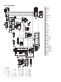
1
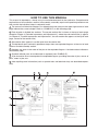
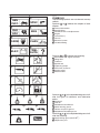
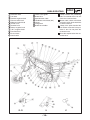
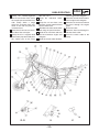
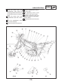
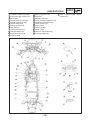
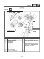
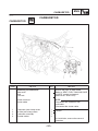
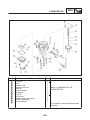
FOREWORD
This Supplementary Service Manual has been prepared to introduce new service and data for the
TW125 2002. For complete service information procedures it is necessary to use this Supplementary
Service Manual together with the following manual.
TW125 SERVICE MANUAL: 5EK1-AE1
TW125 2002
SUPPLEMENTARY
SERVICE MANUAL
E2001 by Yamaha Motor Co., Ltd.
First Edition, August 2001
Any reproduction or unauthorized use
without the written permission of
Yamaha Motor Co., Ltd. is expressly
prohibited.
EB001000
NOTICE
This manual was produced by the Yamaha Motor Company primarily for use by Yamaha dealers and
their qualified mechanics. It is not possible to include all the knowledge of a mechanic in one manual,
so it is assumed that anyone who uses this book to perform maintenance and repairs on Yamaha
motorcycle has a basic understanding of the mechanical ideas and the procedures of motorcycle
repair. Repairs attempted by anyone without this knowledge are likely to render the motorcycle unsafe
and unfit for use.
Yamaha Motor Company, Ltd. is continually striving to improve all its models. Modifications and
significant changes in specifications or procedures will be forwarded to all authorized Yamaha dealers
and will appear in future editions of this manual where applicable.
NOTE:
Designs and specifications are subject to change without notice.
EAS00004
IMPORTANT INFORMATION
Particularly important information is distinguished in this manual by the following notations.
The Safety Alert Symbol means ATTENTION! BECOME ALERT! YOUR
SAFETY IS INVOLVED!
WARNING
CAUTION:
NOTE:
Failure to follow WARNING instructions could result in severe injury or death to
the motorcycle operator, a bystander or a person inspecting or repairing the
motorcycle.
A CAUTION indicates special precautions that must be taken to avoid damage
to the motorcycle.
A NOTE provides key information to make procedures easier or clearer.
EAS00007
HOW TO USE THIS MANUAL
This manual is intended as a handy, easy-to-read reference book for the mechanic. Comprehensive
explanations of all installation, removal, disassembly, assembly, repair and inspection procedures are
laid out with the individual steps in sequential order.
1 The manual is divided into chapters. An abbreviation and symbol in the upper right corner of each
page indicate the current chapter. Refer to “SYMBOLS” on the following page.
2 Each chapter is divided into sections. The current section title is shown at the top of each page,
except in Chapter 3 (“Periodic Inspections and Adjustments”), where the sub-section title(-s) appear.
(In Chapter 3, “Periodic Inspections and Adjustments”, the sub-section title appears at the top of each
page, instead of the section title.)
3 Sub-section titles appear in smaller print than the section title.
4 To help identify parts and clarify procedure steps, there are exploded diagrams at the start of each
removal and disassembly section.
5 Numbers are given in the order of the jobs in the exploded diagram. A circled number indicates a
disassembly step.
6 Symbols indicate parts to be lubricated or replaced (see “SYMBOLS”).
7 A job instruction chart accompanies the exploded diagram, providing the order of jobs, names of
parts, notes in jobs, etc.
8 Jobs requiring more information (such as special tools and technical data) are described sequentially.
2
1
4
3
8
5
6
7
EAS00009
1
SYMBOLS
2
GEN
INFO
SPEC
3
4
CHK
ADJ
ENG
The following symbols are not relevant to every
vehicle.
Symbols 1 to 9 indicate the subject of each
chapter.
1 General information
2 Specifications
3 Periodic checks and adjustments
4 Engine
5 Carburetor(-s)
6 Chassis
7 Electrical system
8 Troubleshooting
5
6
CARB
CHAS
7
8
ELEC
TRBL
SHTG
9
10
Symbols 9 to 16 indicate the following.
9 Serviceable with engine mounted
11
12
10
11
12
13
14
15
16
13
14
15
16
17
20
23
18
19
21
22
24
Filling fluid
Lubricant
Special tool
Tightening torque
Wear limit, clearance
Engine speed
Electrical data
Symbols 17 to 22 in the exploded diagrams indicate the types of lubricants and lubrication
points.
17
18
19
20
21
22
Engine oil
Gear oil
Molybdenum disulfide oil
Wheel bearing grease
Lithium soap base grease
Molybdenum disulfide grease
Symbols 23 to 24 in the exploded diagrams indicate the following:
23 Apply locking agent (LOCTITER)
24 Replace the part
CONTENTS
SPECIFICATIONS
GENERAL SPECIFICATIONS . . . . . . . . . . . . . . . . . . . . . . . . . . . . . . . . . . . . . . . .
MAINTENANCE SPECIFICATIONS . . . . . . . . . . . . . . . . . . . . . . . . . . . . . . . . . .
ENGINE . . . . . . . . . . . . . . . . . . . . . . . . . . . . . . . . . . . . . . . . . . . . . . . . . . . . . . . . . . . .
CHASSIS . . . . . . . . . . . . . . . . . . . . . . . . . . . . . . . . . . . . . . . . . . . . . . . . . . . . . . . . . . .
ELECTRICAL . . . . . . . . . . . . . . . . . . . . . . . . . . . . . . . . . . . . . . . . . . . . . . . . . . . . . .
CABLE ROUTING . . . . . . . . . . . . . . . . . . . . . . . . . . . . . . . . . . . . . . . . . . . . . . . . . . . . .
1
3
3
4
5
6
PERIODIC CHECKS AND ADJUSTMENTS
INTRODUCTION . . . . . . . . . . . . . . . . . . . . . . . . . . . . . . . . . . . . . . . . . . . . . . . . . . . . . .
PERIODIC MAINTENANCE/LUBRICATION INTERVALS . . . . . . . . .
ENGINE . . . . . . . . . . . . . . . . . . . . . . . . . . . . . . . . . . . . . . . . . . . . . . . . . . . . . . . . . . . . . . . .
ADJUSTING THE ENGINE IDLING SPEED . . . . . . . . . . . . . . . . . . . . .
ADJUSTING THE THROTTLE CABLE FREE PLAY . . . . . . . . . . . .
ELECTRICAL SYSTEM . . . . . . . . . . . . . . . . . . . . . . . . . . . . . . . . . . . . . . . . . . . . . . .
CHECKING AND CHARGING THE BATTERY . . . . . . . . . . . . . . . . . .
REPLACING THE HEADLIGHT BULB . . . . . . . . . . . . . . . . . . . . . . . . . . .
ADJUSTING THE HEADLIGHT BEAM . . . . . . . . . . . . . . . . . . . . . . . . . . .
16
16
18
18
19
21
21
27
28
ENGINE
CLUTCH
...............................................................
29
CARBURETOR
CARBURETOR . . . . . . . . . . . . . . . . . . . . . . . . . . . . . . . . . . . . . . . . . . . . . . . . . . . . . . . .
CHECKING THE CARBURETOR . . . . . . . . . . . . . . . . . . . . . . . . . . . . . . . .
ASSEMBLING THE CARBURETOR . . . . . . . . . . . . . . . . . . . . . . . . . . . . .
INSTALLING THE CARBURETOR . . . . . . . . . . . . . . . . . . . . . . . . . . . . . . .
MEASURING AND ADJUSTING THE FUEL LEVEL . . . . . . . . . . . .
31
34
36
37
37
CHASSIS
FRONT WHEEL AHD BRAKE DISC . . . . . . . . . . . . . . . . . . . . . . . . . . . . . . . . .
REAR WHEEL AND REAR BRAKE . . . . . . . . . . . . . . . . . . . . . . . . . . . . . . . . .
REAR WHEEL . . . . . . . . . . . . . . . . . . . . . . . . . . . . . . . . . . . . . . . . . . . . . . . . . . . . .
REAR BRAKE AND REAR WHEEL SPROCKET . . . . . . . . . . . . . . . .
FRONT FORK . . . . . . . . . . . . . . . . . . . . . . . . . . . . . . . . . . . . . . . . . . . . . . . . . . . . . . . . .
HANDLEBAR . . . . . . . . . . . . . . . . . . . . . . . . . . . . . . . . . . . . . . . . . . . . . . . . . . . . . . . . . .
STEERING HEAD . . . . . . . . . . . . . . . . . . . . . . . . . . . . . . . . . . . . . . . . . . . . . . . . . . . . .
LOWER BRACKET . . . . . . . . . . . . . . . . . . . . . . . . . . . . . . . . . . . . . . . . . . . . . . . .
39
40
40
42
44
45
47
47
ELECTRICAL SYSTEM
IGNITION SYSTEM . . . . . . . . . . . . . . . . . . . . . . . . . . . . . . . . . . . . . . . . . . . . . . . . . . . . 49
CIRCUIT DIAGRAM . . . . . . . . . . . . . . . . . . . . . . . . . . . . . . . . . . . . . . . . . . . . . . . 49
CHECKING THE IGNITION SYSTEM . . . . . . . . . . . . . . . . . . . . . . . . . . . . 50
TW125 2002 WIRING DIAGRAM
GENERAL SPECIFICATIONS
SPECIFICATIONS
GENERAL SPECIFICATIONS
Model
TW125
Model code:
5RS1, 5RS2
Dimensions:
Overall length
Overall width
Overall height
Seat height
Wheelbase
Minimum ground clearance
Minimum turning radius
2,135 mm
,820 mm
1,120 mm
,820 mm
1,350 mm
,255 mm
2,100 mm
Carburetor:
Type/quantity
Manufacturer
MV28/1
TEIKEI
Transmission:
Primary reduction system
Primary reduction ratio
Secondary reduction system
Secondary reduction ratio
Transmission type
Operation
Gear ratio
1st
2nd
3rd
4th
5th
Spur gear
74/20 (3.700)
Chain drive
51/14 (3.643)
Constant mesh 5 speed
Left foot operation
36/16 (2.250)
31/21 (1.476)
27/24 (1.125)
25/27 (0.926)
23/29 (0.793)
Chassis:
Frame type
Caster angle
Trail
Diamond
25_50’
93 mm
Tire:
Type
Size
front
rear
Manufacture front
rear
Type
front
rear
Tube type
130/80-18 66P
130/80-18 M/C 66P
180/80-14 M/C 78P
BRIDGESTONE
BRIDGESTONE
TW203
TW204
–1–
SPEC
GENERAL SPECIFICATIONS
Model
TW125
Wheel travel:
Front wheel travel
Rear wheel travel
150 mm
150 mm
Electrical:
Ignition system
Generator system
Battery type
Battery capacity
C.D.I.
A.C. magneto
GT6B-3
12 V 6 AH
Bulb wattage
quantity:
Headlight
Auxiliary light
Tail/brake light
Turn signal light
Meter light
High beam indicator light
Neutral indicator light
Turn signal indicator light
12 V 60 W/55 W
12 V 4 W
1
12 V 5 W/21 W
12 V 21 W
4
12 V 3.4 W
1
12 V 3.4 W
1
12 V 3.4 W
1
12 V 3.4 W
1
–2–
1
1
SPEC
MAINTENANCE SPECIFICATIONS
SPEC
MAINTENANCE SPECIFICATIONS
ENGINE
Item
Standard
Limit
Clutch:
Friction plate thickness
Quantity
Clutch plate thickness
Quantity
Clutch spring free length
Quantity
Push rod bending limit
2.9 X 3.1 mm
5 pcs.
1.6 mm
4 pcs.
34.9 mm
4 pcs.
SSS
2.7 mm
SSS
0.05 mm
SSS
33.9 mm
SSS
0.2 mm
Carburetor:
Type
I.D. mark
Main jet
Main air jet
Jet needle
Needle jet
Pilot air jet 1
Pilot air jet 2
Pilot outlet
Pilot jet
Bypass 1
Bypass 2
Bypass 3
Bypass 4
Pilot screw
Valve seat size
Starter jet 1
Starter jet 2
Fuel level
Engine idle speed
Intake vacuum
MV28
5RS1 00
#134
ø1.2
5A50-3/5
B1/60
#90
#120
0.8
#34
0.7
0.7
0.7
0.7
1-1/2
1.6
0.6
0.8
0 X 2.0 mm
1,450 X 1,650 r/min
190 X 230 mmHg
SSS
SSS
SSS
SSS
SSS
SSS
SSS
SSS
SSS
SSS
SSS
SSS
SSS
SSS
SSS
SSS
SSS
SSS
SSS
SSS
(M.J)
(M.A.J)
(J.N)
(N.J)
(P.A.J.1)
(P.A.J.2)
(P.O)
(P.J)
(B.P.1)
(B.P.2)
(B.P.3)
(B.P.4)
(P.S)
(V.S)
(G.S.1)
(G.S.2)
(F.L)
TIGHTENING TORQUES
ENGINE
Part to be tightened
g
Cam sprocket cover
Oil filter cover
Crankcase (left and right)
Generator cover
Clutch cover
Clutch boss
Drive sprocket
Pick up coil
Stator coil
Thread
Part name
size
Screw
Screw
Screw
Screw
Screw
Nut
Bolt
Screw
Screw
–3–
M6
M6
M6
M6
M6
M14
M5
M6
M6
Q’ty
y
2
2
12
10
10
1
2
2
3
Tightening
torque
Nm
mSkg
10
10
10
10
10
50
4
10
10
1.0
1.0
1.0
1.0
1.0
5.0
0.4
1.0
1.0
Remarks
MAINTENANCE SPECIFICATIONS
SPEC
CHASSIS
Item
Standard
Limit
Front suspension:
Front fork travel
Fork spring free length
Fitting length
Spring rate (K1)
Stroke
(K1)
Oil capacity
Oil level
Oil grade
Inner tube vend limit
150 mm
330 mm
325 mm
4.9 N/mm (0.49 kg/mm)
0 X 150 mm
0.259 L (259 cm3)
122 mm
Fork oil 10 WT or equivalent
SSS
SSS
323 mm
SSS
SSS
SSS
SSS
SSS
SSS
0.2 mm
Rear suspension:
Shock absorber stroke
Spring free length
Fitting length
Spring rate (K1)
Stroke
(K1)
48 mm
190 mm
185 mm
127 N/mm (12.7 kg/mm)
0 X 48 mm
SSS
171 mm
SSS
SSS
SSS
Drive chain:
Type/manufacturer
No. of links
Chain free play
Maximum ten-link section
428HD/DAIDO
125
35 X 60 mm
129.5 mm
SSS
SSS
SSS
SSS
Leading, trailing
130 mm
4 mm
Cam side 52 mm
Pin side 48 mm
SSS
131 mm
2 mm
SSS
5 X 8 mm
SSS
Rear brake:
Type
Drum inside diameter
Shoe thickness
Shoe spring free length
Brake lever:
Brake lever free play (at lever end)
–4–
SPEC
MAINTENANCE SPECIFICATIONS
TIGHTENING TORQUES
CHASSIS
Part to be tightened
g
Thread size
Headlight and headlight stay
Handle crown and steering shaft
Steering ring nut
Brake hose union bolt (front brake)
Swingarm pivot shaft
Footrest (left)
(right)
Rear footrest
Brake caliper and front fork
Rear wheel sprocket and hub
M8
M22
M25
M10
M12
M12
M10
M8
M10
M8
Tightening
torque
Nm
mSkg
16
110
4
30
83
88
48
16
40
43
1.6
11.0
0.4
3.0
8.3
8.8
4.8
1.6
4.0
4.3
Remarks
Refer to NOTE
NOTE:
1. When tighten the ring nut, should be steady the ball bearings and the steering shaft moving smoothly.
2. First, tighten the ring nut approximately 38 Nm (3.8 mSkg) by using the torque wrench, then loosen
the ring nut one turn and retighten the ring nut to specification.
ELECTRICAL
Item
Charging system:
Type
Model/manufacturer
Standard output
Stator coil resistance/color
Battery:
Specific gravity
Electric starter system:
Type
Starter motor:
Model/manufacturer
Output
Armature coil resistance
Brush overall length
Brush spring pressure
Commutator diameter
Mica undercut (depth)
Standard
Limit
C.D.I. magneto
F5BT/YAMAHA
14 V 170 W/5,000 r/min
0.48 X 0.72 Ω at 20_C/
White – White
SSS
SSS
SSS
SSS
SSS
1.320
SSS
Constant mesh type
SSS
5RS/YAMAHA
0.4 kW
0.0126 X 0.0154 Ω at 20_C
10 mm
5.52 X 8.28 N (552 X 828 g)
22 mm
1.5 mm
SSS
SSS
SSS
3.5 mm
SSS
21 mm
SSS
–5–
CABLE ROUTING
SPEC
CABLE ROUTING
1 Brake hose
12 Wire harness
2 Throttle cables
13 Front turn signal light lead (right)
3 Front brake light switch lead
14 Indicator lead
4 Right handlebar switch lead
5 Main switch lead
6 Clutch cable
7 Clutch switch lead
8 Speedometer cable
9 Left handlebar switch lead
10 Front turn signal light lead (left)
11 Meter lead
–6–
A Clamp the grommet of brake
hose with the band. After
completion of clamping, cut the
surplus part and point it to the
backward.
B No positioning for the headlight
body is specified.
C To the headlight
CABLE ROUTING
1 Battery positive lead
13 Diode
2 Starter relay
14 Resister lead
3 Starter motor lead
15 Turn signal relay
4 Clamp
5 Ignition coil
6 Throttle cable (pull side)
7 Throttle cable (return side)
8 Throttle cable holder
9 Horn lead
10 Spark plug lead
11 Relay (White)
12 C.D.I. unit
–7–
SPEC
A After clamping the wire harness,
point the surplus part to the
downward. Clamp the part immediately before the junction to
the C.D.I. unit and relay.
B Cut it to be 10 mm or less.
C Handlebar switch lead (right)
and front brake light switch lead
should not be twined around.
CABLE ROUTING
D Clamp the wire harness, handle
switch lead, main switch lead,
bar switch lead (right), front
resonator hose and starter
brake light switch lead, clutch
cable.
switch lead and main switch F Clamp the ignition coil lead and
lead. After clamping, point the
the ignition coil grand lead horn
surplus part to the downward
lead.
and then cut it. Do not clamp the G Route the wire harness, handleresonator hose and starter
bar switch lead (right) and front
cable.
brake light switch lead through
E Clamp the wire harness, handlethe guide.
bar switch lead (right), front H Do not bend the lead sharply just
brake light switch lead, clutch
after the terminal connection.
–8–
SPEC
I Pass the throttle cables through
the engine bracket hole. Point
the surplus part to the downward
and cut the end.
J Pass the carburetor heater lead
in front of the seat pillar tube so
that it is not caught between the
side cover flange and seat pillar
tube frame.
K Point the rear brake switch lead
wire to the rear side of frame.
CABLE ROUTING
L Clamp the rear brake switch lead O Clamp the wire harness and
connector and turn signal relay
diode. Point the surplus part to
lead with the band and point the
the downward.
surplus part to the inner side,
then cut it. Secure the connector
at the front part of frame.
M Push the wire harness in between frame and box.
N Place the C.D.I. unit on the
mounting port for the left side
relay.
–9–
SPEC
CABLE ROUTING
1 Resonator hose
13 Clutch cable guide
2 Fuel hose
14 Brake hose
3 Rectifier/ regulator lead
15 Speedometer cable
4 Thermo switch lead
16 Handlebar switch lead (left)
5 Sidestand switch lead
17 Clamp
6 Air filter case
18 Flange bolt
7 Breather hose
19 Brake hose holder
8 Battery negative lead
9 C.D.I. magneto leads
10 Over flow hose
11 Air vent hose
12 Clutch cable
–10–
SPEC
A Clamp between the positioning
belts of resonator hose. Do not
pinch the resonator hose.
B Starter cable, clutch switch lead
and main switch lead should not
be twined around.
C Clamp at the point ahead of the
part where resonator hose protector is torn. Do not pinch the
resonator hose.
D Place the coupler below the resonator hose.
CABLE ROUTING
E Clamp the rectifier / regulator
lead and resonator hose. Point
the surplus part toward the inner
side. Clamp within a range
where the resonator hose protector is torn. Do not pinch the
resonator hose.
F Place the air vent hose in the inner side of the main pipe.
G Clamp the C.D.I. magneto lead
at the frame pipe bend and point
the surplus part to the inner
SPEC
side, then cut it.
tween engine and swingarm.
H Clamp the sidestand switch M Route the neutral switch lead belead.
tween engine and swingarm.
I Clamp the air vent hose, over N Route the air vent hose and over
flow hose, starter motor lead and
flow hose through the engine
neutral switch lead.
guide.
J Hold down the side stand switch O To the fuel cock.
lead using the special washer.
P Route the horn lead through inK Route the air vent hose and over
side the clutch cable.
flow hose between engine and Q Insert the starter cable to the
swingarm.
clamp.
L Route the starter motor lead be-
–11–
CABLE ROUTING
R Clamp the brake hose and V Place the speedometer cable in
speedometer cable. Align the
the inner side.
clamping position with the center W After tightening screws, insert
of white paint mark on the brake
the hose in the screw section.
hose.
X Distortion should be within this
S Clamp the brake hose and
range toward the traveling direcspeedometer cable with a holdtion of vehicle.
er.
Y Place the brake hose in the outer
T Point the speedometer cable
side.
cap to the backward.
U Make sure to push in the boot fully.
–12–
SPEC
CABLE ROUTING
1 Handlebar switch lead (right)
13 Battery negative lead
2 Front brake light switch lead
14 Grommet
3 Brake hose
15 Rectifier/ regulator
4 Throttle cable (return side)
16 Clamp (rectifier / regulator lead)
5 Throttle cable (pull side)
17 Handlebar switch lead (left)
6 Starter motor lead
18 Clutch switch lead
7 Battery positive lead
19 Clutch cable
8 Wire harness
20 Master cylinder
9 Clamp (wire harness)
21 Starter cable
10 Thermo switch lead
22 Rear turn signal light lead
11 Sidestand switch lead
23 Turn signal light stay
SPEC
24 C.D.I. magneto leads, neutral
switch lead
12 Negative lead
–13–
CABLE ROUTING
A Clamp the handlebar switch lead D Clamp the wire harness and rear
and front brake light switch lead
turn signal light lead (right). Point
with a band.
the surplus part to the inner side.
B Clamp the throttle cables.
E Cover the naked part of rear turn
C Clamp the C.D.I. magneto lead
signal light lead (right) with the
(2 leads), starter motor lead,
hose.
neutral switch lead, battery neg- F Cover the naked part of rear turn
ative lead and pass them
signal light lead (left) with the
through the frame gusset hole,
hose.
then point the surplus part to the G Clamp the wire harness and rear
inner side.
turn signal lead (right).
–14–
SPEC
H Pass the rear turn signal light
lead (right) between the rear
frame and license bracket,
avoiding to be caught.
I Pass the rear turn signal light
lead (left) between the rear
frame and license bracket,
avoiding to be caught.
J Clamp the rear turn signal light
lead (left). After clamping, point
the surplus part to the inner side.
CABLE ROUTING
K Clamp the thermo switch lead O Clamp the handlebar switch lead
coupler. After clamping, point
(left) and clutch switch lead.
the surplus part to the inner side. P After clamping, cut where it is not
L Pass the C.D.I. magneto lead (2
visible either from the top or the
leads) through the grommet
rear.
side.
M Place the cover to the corner of
rectifier / regulator.
N No special order is set for the
C.D.I. magneto lead (2 leads),
neutral switch lead, starter motor
lead and battery negative lead.
–15–
SPEC
INTRODUCTION
PERIODIC MAINTENANCE/LUBRICATION INTERVALS
CHK
ADJ
EAS00036
PERIODIC CHECKS AND ADJUSTMENTS
INTRODUCTION
This chapter includes all information necessary to perform recommended checks and adjustments. If
followed, these preventive maintenance procedures will ensure more reliable vehicle operation, a
longer service life and reduce the need for costly overhaul work. This information applies to vehicles
already in service as well as to new vehicles that are being prepared for sale. All service technicians
should be familiar with this entire chapter.
EAS00037
PERIODIC MAINTENANCE/LUBRICATION INTERVALS
NOTE:
S The annual checks must be performed every year, except if a kilometer-based maintenance is
performed instead.
S From 30,000 km, repeat the maintenance intervals starting from 6,000 km.
S Items marked with an asterisk should be performed by a Yamaha dealer as they require special tools,
data and technical skills.
NO.
ITEM
ODOMETER READING
( 1,000 km)
CHECK OR MAINTENANCE JOB
1
1
*
2
6
12
18
24
Fuel line
S Check fuel hoses for cracks or damage.
√
√
√
√
Spark
p
plug
p g
S Check condition.
S Clean and regap.
√
S Replace.
3
*
4
6
7
8
Valves
Air filter element
5
Clutch
*
*
*
ANNUAL
CHECK
Front brake
Rear brake
Brake hose
√
√
S Check valve clearance.
S Adjust.
√
S Clean.
√
S Replace.
√
√
√
√
√
S Check operation, fluid level and vehicle for fluid leakage.
√
√
S Replace brake pads.
√
√
√
S Check operation.
S Adjust.
√
√
√
√
√
√
√
S Check operation and adjust brake pedal free play.
√
√
S Replace brake shoes.
√
√
√
√
S Replace.
√
√
√
S Check runout, spoke tightness and for damage.
S Tighten spokes if necessary.
√
√
√
√
10
*
Tires
S
S
S
S
√
√
√
√
11
*
Wheel bearings
S Check bearing for looseness or damage.
√
√
√
√
12
*
Swingarm
S Check operation and for excessive play.
√
√
√
√
15
*
*
16
Steering bearings
√
Every 4 years
Wheels
14
√
Whenever worn to the limit
S Check for cracks or damage.
*
Drive chain
√
Whenever worn to the limit
9
13
√
Check tread depth and for damage.
Replace if necessary.
Check air pressure.
Correct if necessary.
S Lubricate with lithium-soap-based grease.
Every 24,000 km
S Check chain slack.
S Make sure that the rear wheel is properly aligned.
S Clean and lubricate.
S Check bearing play and steering for roughness.
√
Every 500 km and after washing
the motorcycle or riding in the rain
√
√
S Lubricate with lithium-soap-based grease.
√
√
√
Every 24,000 km
Chassis fasteners
S Make sure that all nuts, bolts and screws are properly
tightened.
√
√
√
√
√
Sidestand
S Check operation.
S Lubricate.
√
√
√
√
√
√
17
*
Sidestand switch
S Check operation.
√
√
√
√
18
*
Front fork
S Check operation and for oil leakage.
√
√
√
√
√
19
*
Shock absorber
assembly
S Check operation and shock absorber for oil leakage.
√
√
√
√
–16–
CHK
ADJ
PERIODIC MAINTENANCE/LUBRICATION INTERVALS
NO.
ITEM
ODOMETER READING
( 1,000 km)
CHECK OR MAINTENANCE JOB
1
S Check operation.
ANNUAL
CHECK
6
12
18
24
√
√
√
√
20
*
Rear suspension relay
arm and connecting
arm pivoting points
21
*
Carburetor
S Check starter (choke) operation.
S Adjust engine idling speed.
√
√
√
√
√
√
22
Engine oil
S Change.
S Check oil level and vehicle for oil leakage.
√
√
√
√
√
√
23
Engine oil filter
element
S Clean.
√
*
Engine oil strainer
S Clean.
√
*
Front and rear brake
switches
S Check operation.
√
Moving parts and
cables
S Lubricate.
Lights, signals and
switches
S Check operation.
S Adjust headlight beam.
24
25
26
27
*
S Lubricate with lithium-soap-based grease.
√
√
√
√
√
√
√
√
√
√
√
√
√
√
√
√
√
√
√
√
NOTE:
D The air filter needs more frequent service if you are riding in unusually wet or dusty areas.
D Hydraulic brake service
S Regularly check and, if necessary, correct the brake fluid level.
S Every two years replace the internal components of the brake master cylinder and caliper, and
change the brake fluid.
S Replace the brake hoses every four years and if cracked or damaged.
–17–
ADJUSTING THE ENGINE IDLING SPEED
CHK
ADJ
ENGINE
EAS00054
ADJUSTING THE ENGINE IDLING SPEED
NOTE:
Prior to adjusting the engine idling speed, the air
filter should be clean, and the engine should
have adequate compression.
1. Start the engine and let it warm up for several
minutes.
2. Install:
S engine tachometer
(to the spark plug lead)
Engine tachometer
90890-03113
3. Measure:
S engine idling speed
Out of specification ! Adjust.
Engine idling speed
1,450 X 1,650 r/min
4. Adjust:
S engine idling speed
a. Turn the pilot screw 1 in or out until it is lightly seated.
b. Turn the pilot screw out the specified number
of turns.
Pilot screw
1-1/2 turns out
c. Turn the throttle stop screw 2 in direction a
or b until the specified engine idling speed is
obtained.
Direction a ! Engine idling speed is
increased.
Direction b ! Engine idling speed is
decreased.
5. Adjust:
S throttle cable free play
Refer to “ADJUSTING THE THROTTLE
CABLE FREE PLAY”.
Throttle cable free play
(at the flange of the throttle grip)
3 X 5 mm
–18–
ADJUSTING THE THROTTLE CABLE FREE PLAY
CHK
ADJ
EAS00058
ADJUSTING THE THROTTLE CABLE FREE
PLAY
NOTE:
Prior to adjusting the throttle cable free play, the
engine idling speed should be adjusted.
1. Check:
S throttle cable free play a
Out of specification ! Adjust.
Throttle cable free play
(at the flange of the throttle grip)
3 X 5 mm
2. Adjust:
S throttle cable free play
NOTE:
When the motorcycle is accelerating, the accelerator cable 1 is pulled.
Carburetor side
a. Loosen the locknut 2 on the decelerator
cable.
b. Turn the adjusting nut 3 in direction a or b
to take up any slack on the decelerator cable.
c. Loosen the locknut 4 on the accelerator
cable 1 .
d. Turn the adjusting nut 5 in direction a or b
until the specified throttle cable free play is
obtained.
Direction a
Throttle cable free play
is increased.
Direction b
Throttle cable free play
is decreased.
e. Tighten the locknuts.
NOTE:
If the specified throttle cable free play cannot be
obtained on the carburetor side of the cable, use
the adjusting nut on the handlebar side.
Handlebar side
a. Slide back the rubber cover 1 .
b. Loosen the locknut 2 .
c. Turn the adjusting nut 3 in direction a or b
until the specified throttle cable free play is
obtained.
–19–
ADJUSTING THE THROTTLE CABLE FREE PLAY
CHK
ADJ
Direction a
Throttle cable free play
is increased.
Direction b
Throttle cable free play
is decreased.
d. Tighten the locknut.
WARNING
After adjusting the throttle cable free play,
turn the handlebars to the right and to the
left to ensure that this does not cause the engine idling speed to change.
–20–
CHECKING AND CHARGING THE BATTERY
CHK
ADJ
EAS00178
ELECTRICAL SYSTEM
CHECKING AND CHARGING THE BATTERY
WARNING
Batteries generate explosive hydrogen gas
and contain electrolyte which is made of poisonous and highly caustic sulfuric acid.
Therefore, always follow these preventive
measures:
S Wear protective eye gear when handling or
working near batteries.
S Charge batteries in a well-ventilated area.
S Keep batteries away from fire, sparks or
open flames (e.g., welding equipment,
lighted cigarettes).
S DO NOT SMOKE when charging or handling batteries.
S KEEP BATTERIES AND ELECTROLYTE
OUT OF REACH OF CHILDREN.
S Avoid bodily contact with electrolyte as it
can cause severe burns or permanent eye
injury.
First aid in case of bodily contact:
External
S SKIN – Wash with water.
S EYES – Flush with water for 15 minutes and
get immediate medical attention.
Internal
S Drink large quantities of water or milk followed with milk of magnesia, beaten egg or
vegetable oil. Get immediate medical attention.
CAUTION:
S This is a sealed battery. Never remove the
sealing caps because the balance between
cells will not be maintained and battery performance will deteriorate.
S Charging time, charging amperage and
charging voltage for a MF battery are different from those of conventional batteries.
The MF battery should be charged as explained in the charging method illustrations. If the battery is overcharged, the
electrolyte level will drop considerably.
Therefore, take special care when charging
the battery.
–21–
CHECKING AND CHARGING THE BATTERY
CHK
ADJ
NOTE:
Since MF batteries are sealed, it is not possible
to check the charge state of the battery by measuring the specific gravity of the electrolyte.
Therefore, the charge of the battery has to be
checked by measuring the voltage at the battery
terminals.
1. Remove:
S seat
2. Disconnect:
S battery leads
(from the battery terminals)
CAUTION:
First, disconnect the negative lead 1 , then
the positive lead 2 .
3. Remove:
S battery
4. Check:
S battery charge
a. Connect a pocket tester to the battery terminals.
Open-circuit voltage (V)
Tester positive lead ! battery positive
Tester positive lead ! terminal
Tester negative lead ! battery negative
Tester negative lead ! terminal
13.0
NOTE:
S The charge state of a MF battery can be
checked by measuring its open-circuit voltage
(i.e., the voltage when the positive terminal is
disconnected).
S No charging is necessary when the open-circuit voltage equals or exceeds 12.8 V.
Relationship between the open-circuit voltage
and the charging time at 20_C
12.5
12.0
11.5
5 6.5
10
Charging time (hours)
These values vary with the temperature, the condition of
the battery plates, and the electrolyte level.
b. Check the charge of the battery, as shown in
the charts and the following example.
Example
c. Open-circuit voltage = 12.0 V
d. Charging time = 6.5 hours
e. Charge of the battery = 20 X 30%
–22–
CHECKING AND CHARGING THE BATTERY
CHK
ADJ
5. Charge:
S battery
(refer to the appropriate charging method illustration)
Charging
Open-circuit voltage (V)
Ambient temperature 20_C
WARNING
Do not quick charge a battery.
Time (minutes)
Check the open-circuit
voltage.
CAUTION:
S Make sure that the battery vent is free of obstructions.
S Never remove the MF battery sealing caps.
S Do not use a high-rate battery charger.
They force a high-amperage current into
the battery quickly and can cause battery
overheating and battery plate damage.
S If it is impossible to regulate the charging
current on the battery charger, be careful
not to overcharge the battery.
S When charging a battery, be sure to remove
it from the motorcycle. (If charging has to
be done with the battery mounted on the
motorcycle, disconnect the negative lead
from the battery terminal.)
S To reduce the chance of sparks, do not
plug in the battery charger until the battery
charger leads are connected to the battery.
S Before removing the battery charger lead
clips from the battery terminals, be sure to
turn off the battery charger.
S Make sure that the battery charger lead
clips are in full contact with the battery terminal and that they are not shorted. A corroded battery charger lead clip may generate heat in the contact area and a weak clip
spring may cause sparks.
S If the battery becomes hot to the touch at
any time during the charging process, disconnect the battery charger and let the battery cool before reconnecting it. Hot batteries can explode!
S As shown in the following illustration, the
open-circuit voltage of a MF battery stabilizes about 30 minutes after charging has
been completed. Therefore, wait 30 minutes after charging is completed before
measuring the open-circuit voltage.
Open-circuit voltage (V)
Ambient
temperature
20_C
Charging condition of the battery (%)
–23–
CHK
ADJ
CHECKING AND CHARGING THE BATTERY
Charging method using a variable voltage charger
Measure the open-circuit
voltage prior to charging.
Connect a charged and
AMP meter to the battery
and start charging.
YES
Make sure that the current
is higher than the standard
charging current written on
the battery.
NOTE:
Voltage should be measured 30
minutes after the machine is stopped.
NOTE:
Set the charging voltage at 16 X 17 V.
(If the setting is lower, charging will be
insufficient. If too high, the battery will
be over-charged.)
NO
By turning the charging
voltage adjust dial, set the
charging voltage at 20 X 24 V.
Adjust the voltage so that the
current is at the standard
charging level.
YES
Monitor the amperage for
3 X 5 minutes to check if the
standard charging current is
reached.
NO
Set the time according to the
charging time suitable for the
open-circuit voltage.
Refer to “Battery condition
checking steps”.
If the current does not
exceed the standard
charging current after 5
minutes, replace the battery.
If charging requires more than 5 hours, it is advisable to check the
charging current after a lapse of 5 hours. If there is any change in the
amperage, readjust the voltage to obtain the standard charging
current.
Measure the battery open-circuit voltage after leaving the battery
unused for more than 30 minutes.
12.8 V or more --- Charging is complete.
12.7 V or less --- Recharging is required.
Under 12.0 V --- Replace the battery.
–24–
CHECKING AND CHARGING THE BATTERY
CHK
ADJ
Charging method using a constant voltage charger
Measure the open-circuit
voltage prior to charging.
NOTE:
Voltage should be measured 30
minutes after the machine is stopped.
Connect a charger and
AMP meter to the battery
and start charging.
YES
Make sure that the current
is higher than the standard
charging current written on
the battery.
Charge the battery until the battery’s
charging voltage is 15 V. Charge the
battery until the battery’s charging
voltage is 15 V.
NO
This type of battery charger cannot
charge the MF battery. A variable
voltage charger is recommended.
NOTE:
Set the charging time at 20 hours
(maximum).
Measure the battery open-circuit
voltage after leaving the battery
unused for more than 30 minutes.
12.8 V or more --- Charging is
complete.
12.7 V or less --- Recharging is
required.
Under 12.0 V --- Replace the battery.
–25–
CHECKING AND CHARGING THE BATTERY
CHK
ADJ
6. Check:
S battery vent
Obstruction ! Clean.
Damage ! Replace.
7. Install:
S battery
8. Connect:
S battery leads
(to the battery terminals)
CAUTION:
First, connect the positive lead 1 , then the
negative lead 2 .
9. Check:
S battery terminals
Dirt ! Clean with a wire brush.
Loose connection ! Connect properly.
10. Lubricate:
S battery terminals
Recommended lubricant
Dielectric grease
11. Install:
S seat
–26–
REPLACING THE HEADLIGHT BULB
CHK
ADJ
EAS00182
REPLACING THE HEADLIGHT BULB
1. Remove:
S bolts 1
S headlight unit
2. Disconnect:
S headlight coupler 1
S headlight bulb cover 2
3. Remove:
S headlight bulb holder 1
S headlight bulb 2
WARNING
Since the headlight bulb gets extremely hot,
keep flammable products and your hands
away from the bulb until it has cooled down.
4. Install:
S headlight bulb New
Secure the new headlight bulb with the headlight bulb holder.
CAUTION:
Avoid touching the glass part of the headlight bulb to keep it free from oil, otherwise
the transparency of the glass, the life of the
bulb and the luminous flux will be adversely
affected. If the headlight bulb gets soiled,
thoroughly clean it with a cloth moistened
with alcohol or lacquer thinner.
5. Install:
S headlight bulb holder
6. Connect:
S headlight bulb holder
S headlight coupler
7. Install:
S headlight unit
–27–
ADJUSTING THE HEADLIGHT BEAM
CHK
ADJ
EAS00184
ADJUSTING THE HEADLIGHT BEAM
1. Adjust:
S headlight beam (vertically)
a. Turn the adjusting screw 1 in direction a or
b.
Direction a ! Headlight beam is
raised.
Direction b ! Headlight beam is
lowered.
2. Adjust:
S headlight beam (horizontally)
a. Turn the adjusting knob 2 in direction a or
b.
Direction a ! Headlight beammoves
to the right.
Direction b ! Headlight beammoves
to the left.
–28–
CLUTCH
ENG
EAS00274
ENGINE
CLUTCH
8 Nm (0.8 mSkg)
70 Nm (7.0 mSkg)
12 Nm (1.2 mSkg)
6 Nm (0.6 mSkg)
Order
1
2
3
4
5
6
7
8
9
10
11
Job/Part
Removing the clutch
Clutch springs
Pressure plate
Friction plates
Clutch plates
Nut/Lock washer
Clutch boss
Thrust washer
Clutch housing
Ball
Long clutch push rod
Push lever screw/Gasket
Q’ty
Remarks
Remove the parts in the order listed.
4
1
5
4
1/1
1
1
1
1
1
1/1
–29–
Refer to “REMOVING/INSTALLING
THE CLUTCH” section in chapter 4.
(Manual No.: 5EK1-AE1)
CLUTCH
8 Nm (0.8 mSkg)
ENG
70 Nm (7.0 mSkg)
12 Nm (1.2 mSkg)
6 Nm (0.6 mSkg)
Order
Job/Part
Q’ty
1
12
Push lever axle
13
14
15
16
Torsion spring
Circlip
Oil seal
Nut/Washer
1
1
1
1/1
17
18
Short clutch push rod/O-ring
Push plate
1/1
1
Remarks
Refer to “INSTALLING THE CLUTCH”
section in chapter 4.
(Manual No.: 5EK1-AE1)
Refer to “INSTALLING THE CLUTCH”
section in chapter 4.
(Manual No.: 5EK1-AE1)
For installation, reverse the removal
procedure.
–30–
CARBURETOR
ENG
EAS00480
CARBURETOR
CARBURETOR
Order
1
2
3
4
Job/Part
Q’ty
Remarks
Removing the carburetor
Side cover
Seat
Fuel tank
Remove the parts in order listed.
Refer to “SEAT, FUEL TANK AND SIDE
COVER” section in chapter 3.
(Manual No.: 5EK1-AE1)
Heater unit lead
Starter cable
NOTE:
S Disconnect the connector from
carburetor.
S Disconnect the starter cable.
Carburetor joint clamp screw
Air filter joint clamp screw
Carburetor assembly
Throttle cables
1
1
1
2
Loosen.
For installation, reverse the removal
procedure.
–31–
CARBURETOR
ENG
EAS00483
Order
1
2
3
4
5
6
7
8
9
10
11
Job/Part
Disassembly the carburetor
Vacuum chamber cover
Piston valve spring
Jet needle holder
Jet needle spring
Jet needle
Piston valve
Carburetor heater
Adjusting screw
Drain screw
Float chamber
Gasket
Q’ty
Remarks
Disassemble the parts in the order listed.
1
1
1
1
1
1
1
1
1
1
1
–32–
Refer to “ASSEMBLING THE
CARBURETOR”.
CARBURETOR
Order
12
13
14
15
16
17
18
19
20
21
22
23
Job/Part
Float pin
Float
Needle valve
Needle valve seat
Main jet
Main jet holder
Needle jet
Pilot jet
Pilot screw
Rubber diaphragm spring
Rubber diaphragm
Starter plunger
Q’ty
1
1
1
1
1
1
1
1
1
1
1
1
ENG
Remarks
Refer to “ASSEMBLING THE
CARBURETOR”.
For assembly, reverse the disassembly
procedure.
–33–
CARBURETOR
CARB
EAS00485
CHECKING THE CARBURETOR
1. Check:
S carburetor body
S float chamber
S jet housing
Cracks/damage ! Replace.
2. Check:
S fuel passages
Obstruction ! Clean.
a. Wash the carburetor in a petroleum-based
solvent. Do not use any caustic carburetor
cleaning solution.
b. Blow out all of the passages and jets with
compressed air.
3. Check:
S float chamber body
Dirt ! Clean.
4. Check:
S float chamber rubber gasket
Cracks/damage/wear ! Replace.
5. Check:
S float
Damage ! Replace.
6. Check:
S needle valve 1
S needle valve seat 2
Damage/obstruction/wear ! Replace the
needle valve, needle valve seat and O-ring
as a set.
7. Check:
S O-ring 3
Damage/wear ! Replace the needle valve,
needle valve seat and O-ring as a set.
–34–
CARBURETOR
CARB
8. Check:
S piston valve 1
Damage/scratches/wear ! Replace.
S rubber diaphragm 2
Cracks/tears ! Replace.
9. Check:
S vacuum chamber cover 1
S piston valve spring 2
S jet needle holder 3
S jet needle spring 4
Cracks/damage ! Replace.
10. Check:
S jet needle kit 1
S needle jet 2
S main jet 3
S main jet holder 4
S pilot jet 5
S pilot screw 6
Bends/damage/wear ! Replace.
Obstruction ! Clean.
Blow out the jets with compressed air.
11. Check:
Spiston valve movement
Insert the piston valve into the carburetor
body and move it up and down.
Tightness ! Replace the piston valve.
12 Check:
S starter plunger 1
S starter plunger spring 2
Bends/cracks/damage ! Replace.
–35–
CARBURETOR
CARB
13. Check:
S fuel hoses
Cracks/damage/wear ! Replace.
Obstruction ! Clean.
Blow out the hoses with compressed air.
EAS00487
ASSEMBLING THE CARBURETOR
CAUTION:
S Befor assembling the carburetor, wash all
of the parts in a petroleum-based solvent.
S Always use a new gasket.
1. Install:
S needle jet
S main jet 1
S main jet holder 2
S pilot jet 3
2. Install:
S needle valve seat 1
3. Install:
S float 1
S needle valve
S float pin 2
NOTE:
Install the float pin from the side opposite the arrow.
–36–
CARBURETOR
CARB
4. Install:
S float chamber 1
S pilot screw 2
5. Install:
S starter plunger kit 1
EAS00492
INSTALLING THE CARBURETOR
1. Adjust:
S engine idling speed
Engine idling speed
1,450 X 1,650 r/min
Refer to “ADJUSTING THE ENGINE IDLING
SPEED”
2. Adjust:
S throttle cable free play
Throttle cable free play
(at the flange of the throttle grip)
3 X 5 mm
Refer to “ADJUSTING THE THROTTLE
CABLE FREE PLAY”.
EAS00498
MEASURING AND ADJUSTING THE FUEL
LEVEL
1. Measure:
S fuel level a
Out of specification ! Adjust.
Fuel level (below the float chamber
mating surface)
0 X 2.0 mm
–37–
CARBURETOR
CARB
a. Stand the motorcycle on a level surface.
b. Place the motorcycle on a suitable stand to
ensure that the motorcycle is standing
straight up.
c. Install the fuel level gauge 1 to the fuel drain
pipe 2 .
Fuel level gauge
90890-01312
d. Loosen the fuel drain screw 3 .
e. Hold the fuel level gauge vertically next to the
float chamber.
f. Measure the fuel level a .
2. Adjust:
S fuel level
a. Remove the carburetor.
b. Check the needle valve seat and needle
valve.
c. If either is worn, replace them as a set.
d. If both are fine, adjust the float level by slightly bending the float tang 1 .
e. Install the carburetor.
f. Measure the fuel level again.
g. Repeat steps (a) to (f) until the fuel level is
within specification.
–38–
FRONT WHEEL AND BRAKE DISC
CHAS
EAS00512
CHASSIS
FRONT WHEEL AND BRAKE DISC
90 Nm (9.0 mSkg)
13 Nm (1.3 mSkg)
Order
Job/Part
Q’ty
Remove the parts in the order listed.
NOTE:
Place the motorcycle on a suitable stand
so that the front wheel is elevated.
Removing the front wheel and brake
disc
1
2
3
4
5
6
7
Caps
Speedometer cable
Wheel axle
Front wheel assembly
Collar
Meter gear unit assembly
Brake disc
Remarks
2
1
1
1
1
1
1
Refer to “REMOVING/INSTALLING THE
FRONT WHEEL” section in chapter 6.
(Manual No.: 5EK1-AE1)
For installation, reverse the removal
procedure.
–39–
REAR WHEEL AND REAR BRAKE
CHAS
REAR WHEEL AND REAR BRAKE
REAR WHEEL
90 Nm (9.0 mSkg)
Order
Job/Part
Q’ty
Remove the parts in the order listed.
NOTE:
Place the motorcycle on a suitable stand
so that the rear wheel is elevated.
Removing the rear wheel
1
2
3
4
5
6
7
8
Adjuster
Brake rod
Pin
Compression spring
Chain case
Axle nut/washer
Chain pullers
Wheel axle
Remarks
1
1
1
1
1
1/1
2
1
–40–
Refer to “REMOVING/INSTALLING THE
REAR WHEEL” section in chapter 6.
(Manual No.: 5EK1-AE1)
REAR WHEEL AND REAR BRAKE
CHAS
90 Nm (9.0 mSkg)
Order
Job/Part
Q’ty
Remarks
Refer to “REMOVING /INSTALLING THE
REAR WHEEL” section in chapter 6.
(Manual No.: 5EK1-AE1)
9
Rear wheel assembly
1
10
Collar
2
For installation, reverse the removal
procedure.
–41–
REAR WHEEL AND REAR BRAKE
CHAS
REAR BRAKE AND REAR WHEEL SPROCKET
43 Nm (4.3 mSkg)
Order
1
2
3
Job/Part
Removing the rear brake and rear
wheel sprocket
Shoe plate
Nuts
Driven sprocket
Q’ty
Remarks
Remove the parts in the order listed.
1
6
1
–42–
Refer to “ASSEMBLYNG THE REAR
WHEEL” section in chapter 6.
(Manual No.: 5EK1-AE1)
For installation, reverse the removal
procedure.
REAR WHEEL AND REAR BRAKE
Order
1
2
3
4
Job/Part
Disassembling the rear wheel
Bearing
Spacer
Oil seal
Bearing
Q’ty
CHAS
Remarks
Disassemble the parts in the order listed.
1
1
1
1
For assembly, reverse the disassembly
procedure.
–43–
FRONT FORK
CHAS
FRONT FORK
23 Nm (2.3 mSkg)
23 Nm (2.3 mSkg)
23 Nm (2.3 mSkg)
30 Nm (3.0 mSkg)
Order
Job/Part
Q’ty
Remove the parts in the order listed.
Refer to “FRONT WHEEL AND BRAKE
DISC”.
Removing the front fork
Front wheel
1
2
3
4
5
6
7
8
Brake hose holder
Caliper
Front fender
Cap bolt/O-ring
Bolt (upper bracket)
Bolts (under bracket)
Front fork assembly (left)
Front fork assembly (right)
Remarks
1
1
1
1/1
1
2
1
1
Refer to “REMOVING/INSTALLING
THE FRONT FORK” section in
cahpter 6. (Manual No.: 5EK1-AE1)
NOTE:
Loosen the bolt.
For installation, reverse the removal
procedure.
–44–
HANDLEBAR
CHAS
HANDLEBAR
20 Nm (2.0 mSkg)
Order
1
2
3
4
5
6
7
Job/Part
Removing the handlebar
Master cylinder bracket
Master cylinder
Housing (throttle grip)
Throttle grip assembly
Handlebar switch (right)
Clutch switch
Clutch cable
Q’ty
Remarks
Remove the parts in the order listed.
1
1
1
1
1
1
1
–45–
Refer to “INSTALLING THE
HANDLEBAR” section in chapter 6.
(Manual No.: 5EK1-AE1)
HANDLEBAR
CHAS
20 Nm (2.0 mSkg)
Order
Job/Part
Q’ty
8
9
Handlebar switch (left)
Grip (left)
1
1
10
11
12
Clutch lever
Starter cable holder
Upper holders
1
1
2
13
Handlebar
1
Remarks
Refer to “REMOVING THE HANDLEBAR”
section in chapter 6.
(Manual No.: 5EK1-AE1)
Refer to “INSTALLING THE
HANDLEBAR” section in chapter 6.
(Manual No.: 5EK1-AE1)
For installation, reverse the removal
procedure.
–46–
STEERING HEAD
CHAS
STEERING HEAD
LOWER BRACKET
90 Nm (9.0 mSkg)
1st 38 Nm (3.8 mSkg)
2nd 18 Nm (1.8 mSkg)
Order
1
2
3
4
5
6
7
8
9
10
11
12
13
Job/Part
Removing the lower bracket
Front fork
Handlebar
Headlight unit
Headlight body
Turn signal light assembly (left)
Turn signal light assembly (right)
Meter cable/Meter lead
Meter assembly
Headlight stay
Steering stem nut
Handlebar crown
Lock washer
Upper ring nut
Rubber washer
Lower ring nut
Q’ty
Remarks
Remove the parts in the order listed.
Refer to “FRONT FORK”.
Refer to “HANDLEBAR”
1
1
1
1
1/1 NOTE:
Disconnect the connector.
1
2
1
1
1
1
1
Refer to “INSTALLING THE STEERING
1
HEAD” section chapter 6.
(Manual No.: 5EK1-AE1)
–47–
STEERING HEAD
CHAS
90 Nm (9.0 mSkg)
1st 38 Nm (3.8 mSkg)
2nd 18 Nm (1.8 mSkg)
Order
14
15
16
17
18
19
20
Job/Part
Ball race ccver
Lower bracket
Ball race (upper)
Ball
Ball
Ball race (center)
Ball race (lower)
Q’ty
1
1
1
22
19
1
1
Remarks
Refer to “INSTALLING THE STEERING”
section in chapter 6.
(Manual No.: 5EK1-AE1)
For installation, reverse the removal
procedure.
–48–
IGNITION SYSTEM
ELEC
EAS00734
ELECTRLCAL SYSTEM
IGNITION SYSTEM
CIRCUIT DIAGRAM
1 C.D.I. magneto
2 Neutral switch
4 Battery
6 Fuse
10 Engine stop switch
11 Main switch
13 Diode
14 C.D.I. unit
15 Ignition coil
16 Spark plug
22 Neutral relay
24 Reed switch
–49–
IGNITION SYSTEM
EAS00798
CHECKING THE IGNITION SYSTEM.
1. The speedometer fail to come on.
1. Reed switch
S Remove the meter assembly.
S Connect the pocket tester (Ω
reed switch coupler as shown.
1) to the
Tester positive probe ! white/black 1
Tester negative probe ! red/blue 2
S Make the speedometer indicate
S Check the continuity or open circuit status.
S If it counts 4 cycles of continuity and open
actions per speedometer rotation, the result
is acceptable.
S Is the reed switch OK?
YES
Properly connect or
repair the ignition
system.
NO
Replace the reed
switch.
–50–
ELEC
TW125 2002 WIRING DIAGRAM
1
2
3
4
5
6
7
8
9
10
11
12
13
14
15
16
17
18
19
20
21
22
23
24
25
26
27
28
29
30
31
32
33
34
35
36
37
38
39
40
41
42
COLOR CODE
B .........
Br . . . . . . . . .
Ch . . . . . . . .
Dg . . . . . . . .
G .........
L ..........
O .........
Black
Brown
Chocolate
Dark green
Green
Blue
Orange
Sb . . . . . . . .
P .........
R .........
Y .........
W .........
B/ R . . . . . .
B/ W . . . . . .
Sky blue
Pink
Red
Yellow
White
Black/ Red
Black/ White
Br/ L . . . . . .
Br/ W . . . . .
G/R . . . . . .
G/W . . . . . .
G/Y . . . . . .
L/B . . . . . . .
L/R . . . . . . .
Brown/ Blue
Brown/ White
Green / Red
Green / White
Green / Yellow
Blue/ Black
Blue/ Red
L/W . . . . . .
L/Y . . . . . . .
R/ L . . . . . . .
R/ W . . . . . .
W/ B . . . . . .
W/ L . . . . . .
W/ R . . . . . .
Blue/ White
Blue/ Yellow
Red/ Blue
Red/ White
White/ Black
White/ Blue
White/ Red
C.D.I. magneto
Neutral switch
Rectifier/ Regulator
Battery
Starter relay
Fuse
Starter motor
Right handlebar switch
Start switch
Engine stop switch
Main switch
Clutch switch
Diode
C.D.I. unit
Ignition coil
Spark plug
Thermo switch
Carbuletor heater
Horn
Turn signal relay
Sidestand switch
Neutral relay
Speedometer
Reed switch
Meter light
Neutral indicator light
Turn signal indicator light
Hi-beam indicator light
Left handlebar switch
Horn switch
Turn signal switch
Light switch
Dimmer switch
Front brake light switch
Rear brake light switch
Rear turn signal light (right)
Front turn signal light (right)
Front turn signal light (left)
Rear turn signal light (left)
Headlight
Auxiliary light
Tail/ Brake light