1
YAMAHA CONTROLLER NETWORK
YC-Link/E
User s Manual
RCX340
EUS814A100
Ver. 1.00
E104
CONTENTS
YC-Link/E
User’s Manual
1. Overview of YC-Link/E
1
1.1 Overview
1
1.2 Part names of YC-Link/E compatible units
2
2. Installation and settings
3
2.1 Connecting the LAN cables
3
2.2 LAN cable type
4
2.2.1 Noise prevention
4
2.3 YC-Link/E board settings
5
2.3.1 Master board settings
5
2.3.2 Slave board settings
5
2.4 PB connector of YC-Link/E slave controller
5
2.5 CE compliance
6
2.6 Circuit examples
6
2.6.1 Category 3
7
2.6.2 Overview of circuit operation
9
3. Basic specifications
10
3.1 Basic specifications
10
3.2 YC-Link/E master
10
3.3 YC-Link/E slave
10
4. Operation
11
4.1 About power-on timing
11
4.2 Checking the communication establishment between the master and slave
12
4.2.1 LED lighting pattern of the YC-Link/E board (both slave and master)
12
4.2.2 7-segment LED display on the controller
12
4.2.3 Judgment by the dedicated output signal (MPREADY)
12
T-1
CONTENTS
5. Troubleshooting
13
5.1 Check items at YC-Link/E start-up
13
5.2 Meanings of LEDs on the YC-Link/E board
14
5.2.1 Master board
14
5.2.2 Slave board
15
5.3 YC-Link/E related alarms
T-2
YC-Link/E
User’s Manual
16
111 Over view of YC-Link/E
1111
1
Over view
■ ■ About YC-Link/E
■ ■ Control method
The YC-Link/E adopts an EtherCAT Note 1 base communication method for the communication among the controllers.
Therefore, there are one master and one or more slaves, and the master controls the slaves.
The slave is identified from the master using the station number that is set with the rotary switches on the YC-Link/E slave
board.
The master sends various data or commands to the slaves. A station number is written to this send data as send
destination. The slave processes the received data and sends the response. When the master receives the response from
the slave, to which the data was sent, the command process is completed. The master uses the synchronous control that
uses the distributed clock to periodically execute this send/receive process to each slave.
■ ■ YC-Link/E compatible units
The RCX series controller with the YC-Link/E master board installed becomes the master of the YC-Link/E and the
YC-Link/E slave board is installed in the RCX series controller that becomes the slave of the YC-Link/E. The units with
these interfaces are connected using the LAN cables through the multi-drop (daisy chain) to construct a network.
■ ■ Features
In the YC-Link/E system, all operations to the slave RCX series controllers are performed from the master. Therefore, the
program, point data, and parameter of the robot connected to each slave are changed by accessing the master. PC
applications or handy terminals cannot be connected to the slave controllers.
■ ■ Compatible robots
Robots that can be controlled using the YC-Link/E system are YAMAHA's robots applicable to the RCX series.
Note 1. EtherCAT® is registered trademark and patent technology, licensed by Beckhoff Automation Gmbh, Germany.
1
Overview of YC-Link/E
This YC-Link/E system is designed to control multiple RCX series controllers by connecting the multi-axis robot controller
RCX series.
Robot controllers that are connected using the YC-Link/E can be controlled in the same manner as the normal RCX series
robot axes. The user can add robots or axes to the RCX controller without notifying the number of controllers or
differences.
Use of the YC-Link/E makes it possible to expand the robot system with maximum four axes (both physical axes/logical
axes) using single RCX series controller into maximum six axes (logical and physical axes, 12 axes in total) per robot and
the overall system into maximum four robots and 16 axes (physical axes).
1111
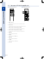
Part names of YC-Link/E compatible units
■ ■ YC-Link/E master board
1
■ YC-Link/E slave board
7
Overview of YC-Link/E
1
9
5
6
3
8
4
5
6
7
7
2
9
7
1
9
111 OUT connector
A RJ-45 modular connector necessary to connect the next slave.
222 IN connector
A RJ-45 modular connector necessary to connect the previous slave.
333 Station number setting switch (tens digit)
A rotary switch to set the station number of the YC-Link/E slave.
444 Station number setting switch (ones digit)
A rotary switch to set the station number of the YC-Link/E slave.
555 RUN LED
A LED to indicate the RUN status.
666 ERR LED
A LED to indicate the ERROR status.
777 LINK LED
A LED to indicate the LINK status.
888 SYS LED
A LED to indicate the SYSTEM status.
999 Not used.
2
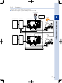
222 Installation and settings
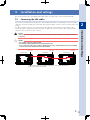
This section describes how to install the YC-Link/E system. For other items, see the controller manuals.
2222
Connecting the LAN cables
w
c
WARNING
Perform the cable connection work after the power to the robot controller has been shut down
completely.
CAUTION
•The YC-Link/E cannot use an Ethernet hub.
•The maximum cable length between the master and slave is 3m.
•Do not connect the cable of the YC-Link/E to the Ethernet port of the controller main body or the RJ-45 modular
connector of the iVY board when the iVY board is installed.
Master unit
Slave unit
RCX340 master
RCX340 slave
1
OPTION
3
RCX340 slave
1
OPTION
1
3
1
3
2
4
2
4
PB
2
4
ROB I/O
1-2
ROB I/O
3-4
M2
M3
M4
(PE) M1
EN
USB
2
4
COM
ROB I/O
1-2
SAFETY
AC IN
M1
1
3
2
4
PB
COM
SAFETY
AC IN
(PE) M1
OPTION
3
4
COM
ROB I/O
3-4
3
1
2
PB
ROB I/O
1-2
Slave unit
ROB I/O
3-4
SAFETY
AC IN
M1
M2
M3
M4
(PE) M1
M1
M2
M3
EN
USB
M4
EN
USB
Do not connect the cable of the YC-Link/E to the Ethernet port of the controller main body or the
RJ-45 modular connector of the iVY board.
3
2
Installation and settings
Connect the YC-Link/E master board and slave board with the LAN cable recommended in section "2.2 LAN
cable type". Insert the modular jack of the LAN cable into the modular connector of the controller until a click
sounds.
Two RJ-45 modular connectors are provided on the YC-Link/E slave board. When connecting the cables,
connect the cable coming from the master board to the upper IN connector and the cable coming from the
subsequent slave to the lower OUT connector.
2222
LAN cable type
Use a LAN cable that prevents the noise from entering the inside of the cable.
Conditions:CAT5E or higher
Twist pair
Dual-shield (Shielded type RJ45 modular plug)
Recommended cable: NWSMC5E-SON-S2SB-SB-*** (Straight cable) (Manufacturer: MISUMI)
(* shows the cable length. Cable length can be specified in 0.1m-steps in a range of 0.5 to 100m.)
2
222222
Noise prevention
Installation and settings
Shielded LAN cables are used for the YC-Link/E system.
Additionally, when using the YC-Link/E system in a severe noise environment, attach a ferrite core to the
shielded LAN cable.
w
4
WARNING
Perform the cable connection work after the power supply to the input power cable has been shut
down completely.
2222
222222
YC-Link/E board settings
Master board settings
When using the RCX series controller with the YC-Link/E master board installed as YC-Link/E master, select the
RCX series controller parameter [Option]-[Option board enable] to set the YC-Link/E master board (option
board) enabled.
After setting, this setting is reflected when the control power to the RCX series controller is turned on again.
When the RCX series controller parameter [Option board enable] is set disabled, the RCX series controller can
be operated as a single controller not as YC-Link/E master.
Slave board settings
When using the RCX series controller with the YC-Link/E slave board installed as YC-Link/E slave, it is
necessary to set the rotary switches on the YC-Link/E slave board.
Each slave of the YC-Link/E has a unique node ID and this number is used to perform the communication. Set
the slave station number with the rotary switches on the YC-Link/E slave board. To set the station number, turn
the arrow mark at the center of the rotary switch with a slotted screwdriver.
The upper switch indicates tens digit and the lower switch indicates ones digit. A station number ranging from
1 to 99 is set.
After changing the rotary switches, this setting is reflected when the control power to the RCX series controller
is turned on again.
When "0" is set, the RCX series controller can be operated as a single controller not as YC-Link/E slave.
2222
PB connector of YC-Link/E slave controller
The YC-Link/E slave unit cannot use the programming box. So, connect the dummy connector supplied with
the RCX series controller to the PB connector.
5
Installation and settings
222222
2
2222
CE compliance
When controlling multiple robots using the YC-Link/E function, relevant items stated in "Control of multiple
robots" of the EN ISO 10218-1 standard shall be satisfied.
Additionally, the requirements shown below shall also be satisfied in the same manner as one robot.
In the customer's final system, the performance level (PLr) required of the safety circuit should be
determined by means of risk assessment, and then the safety circuit with the corresponding performance
level (PL) should be configured.
2
The following shows an example for conformance.
Installation and settings
111 Single pendant control
• To control all robots with the single programming box (pendant), the programming box is connected only to the master
controller so as to perform the operation. The programming box cannot be operated with the slave controller.
• To operate the robots individually or at the same time, select a relevant robot using the robot selection menu on the
programming box.
222 Safety requirements
• To put all robots in the same operation mode, an operation mode selector switch is installed and the operation mode
is input only to the master controller. The master controller sets all slave controllers in the same operation mode.
• To put all robots in the power shutdown enable status, an operation robot selector switch is installed and a power
shutdown circuit that interlocks with the operation robot selector switch is installed in all robots.
• To clearly indicate the selected robot, an indicator is installed at legible location of the selected robot.
2222
Circuit examples
Safety circuit examples are shown when controlling multiple robots with the YC-Link/E function.
To safely operate the robots, take safety measures suitable for the customer's equipment while referring to
safety circuit configuration examples.
Examples with the following input and output signals are shown.
Input
Output
c
6
Operation mode switch, door switch, external emergency stop, PBX-E enable, MP RDY
Contactor, E-STOP RDY, AUTO
CAUTION
The controller status output signals of the parallel I/O and serial I/O, such as alarm signal should be monitored by
the host device or safety controller.
222222
Categor y 3
Category 3 safety circuit examples are shown below.
■ ■ Over view diagram of system (Multiple robots are used)
Programming box
2
PLC
Indicator
Power supply wiring
Safety circuit
Controller (master)
OPTION
3
4
1
3
2
4
Installation and settings
1
2
PWR
Robot 1
PB
COM
ROB I/O
1-2
ROB I/O
3-4
SAFETY
AC IN
(PE) M1
BAT1
M1
BAT2
M2
BAT3
M3
M4
BAT4
EN
USB
SAFETY connector
PB connector: Not used.
Power supply wiring
Safety circuit
Controller (slave)
OPTION
1
3
2
4
1
3
2
4
Indicator
PWR
Robot 2
PB
COM
ROB I/O
1-2
ROB I/O
3-4
SAFETY
AC IN
(PE) M1
BAT1
M1
BAT2
M2
BAT3
M3
BAT4
M4
EN
USB
To other controller (slave)
7
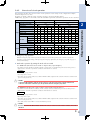
■ ■ Categor y 3 safety circuit example (Multiple robots are used.)
Power supply wiring
Safety circuit
Earth
leakage
circuit
breaker
L
N
L1
N1
Circuit
protector
Noise
filter
KM1
Serge
absorber
2
Mode
a
KM2
L
N
Circuit
protector
Close Open
MANUAL
Open Close
S1
Installation and settings
S2
Safety door
Si2
Si14
Si3
Si15
+24V
S3
Robot 1 selection
O0
O1
O2
Si7
Selection b-contact
ON
Close
OFF
Open
O3
Si6
Indicator 2
I02
Si8
S5
Robot 3 selection
+24V
Expanded
I/O I00 Robot 1
I01
I03
Si9
PB
A2
A3
B2
B3
A7
A8
B7
B8
A1
A4
A5
A6
B1
B4
B5
B6
A9
A10
B9
B10
A11
A12
B11
B12
Indicator 1
S4
Robot 2 selection
Motor power
Emergency
stop
Si4
Si5
Control power
SAFETY
Si19
T0
Si12
T1
Si13
Si0
Si1
a
b
Mode selection
Master
S7
Optional
emergency
stop
SRL1
G9SP T2
O4
b
AUTO
PBX-E
Controller (PNP)
AC IN
AC power supply
Robot 2
13
14
15
16
17
18
19
20
26
E-STOP 1+ (+24V) /PB 25
E-STOP RDY 1
E-STOP COM 1
E-STOP 1- (24VGND)
E-STOP 2+ (+24V)
E-STOP RDY 2
E-STOP COM 2
E-STOP 2- (24VGND)
Enable
AUTO status 1
AUTO status 2
MP RDY status 1
MP RDY status 2
Robot 3
Robot 4
Indicator 3
Robot 2
T3
Si16
O5
T4 Robot 3
Si17
O6
T5 Robot 4
Si18
O7
Si10
S6
Robot 4 selection
Si11
Indicator 4
+24V
DC power supply
GND
V1,V2
G1,G2
YC-Link/E
AC power supply
Earth
leakage
circuit
beaker
L
N
AC IN
Noise
filter
L1
N1
Circuit
protector
KM3
Serge
absorber
KM4
L
N
Circuit
protector
Slave
Control power
Motor power
PB
SAFETY
A2
A3
B2
B3
A7
A8
B7
B8
A1
A4
A5
A6
B1
B4
B5
B6
A9
A10
B9
B10
A11
A12
B11
B12
13
14
15
16
17
18
19
20
Not used.
E-STOP 1+ (+24V)
E-STOP RDY 1
E-STOP COM 1
E-STOP 1- (24VGND)
E-STOP 2+ (+24V)
E-STOP RDY 2
E-STOP COM 2
E-STOP 2- (24VGND)
AUTO status 1
AUTO status 2
MP RDY status 1
MP RDY status 2
Parts list
Circuit number
8
Part name
Model name
Manufacturer
S1
Key selector switch
A22TK series
OMRON
S2
Safety door switch
D4series
OMRON
S3-6
Selector switch
XB5 series
SCHNEIDER ELECTRIC
S7
Emergency stop button
A22Eseries
OMRON
KM1-4
Contactor (mirror contact)
3RTseries
SIEMENS
SRL1
Safety controller
G9SPseries
OMRON
222222
Over view of circuit operation
The following describes the overview of the circuit operation of each safety circuit configuration example
shown in the previous section.
Programs are made so that the safety controller operates as shown in the table below.
Additionally, programs are also made so that the standard requirements other than operations are also satisfied.
Operation mode
AUTO mode outside safety enclosure
Input a: Close / Input b: Open
Mode selector switch
Emergency stop button
Open
Open
Safety door
–
Open
Enable switch
–
–
–
–
–
Robot 1 SEL
–
–
Close
–
–
Robot 2 SEL
–
–
–
Close
Robot 3 SEL
–
–
–
–
Close
Close
Open
–
–
–
Open
–
–
–
–
Close
–
–
–
–
–
–
–
Close
–
–
–
–
–
Close
–
–
Close
–
–
–
Close
–
–
–
–
–
Close
–
–
–
–
–
–
Close
–
–
ON
–
–
–
–
–
–
ON
–
–
–
Robot 2
–
–
–
ON
–
–
–
–
–
–
ON
–
–
Robot 3
–
–
–
–
ON
–
–
–
–
–
–
ON
–
Robot 4
–
–
–
–
–
ON
–
–
–
–
–
–
ON
OFF
OFF
OFF
OFF
OFF
Robot 1
OFF
OFF
ON
–
–
–
Robot 2
OFF
OFF
–
Robot 3
OFF
OFF
–
Robot 4
OFF
OFF
–
ON
E-STOP RDY
Contactor
–
–
AUTO mode
Output
2
Close
Robot 1
Robot 4 SEL
MP RDY
Input a: Open / Input b: Close
Close
OFF
ON
ON
–
–
OFF
OFF
OFF
ON
–
ON
–
–
OFF
OFF
OFF
–
ON
–
–
–
ON
–
OFF
OFF
OFF
–
–
ON
–
–
–
ON
OFF
OFF
OFF
–
–
–
ON
111 Emergency stop operation
When the emergency stop switch is pressed, the main power (motor drive power) to the controller is shut down.
Regardless of other switch settings, when pressing the emergency stop button, the emergency stop with category 0 is
activated immediately.
222 Each mode operation by setting the mode selector switch
2.1 AUTO mode (The mode selector switch is "Input a: Close, Input b: Open".)
The enable switch on the PBX-E is disabled, and the contactor turns on and the main power (motor drive power) is
supplied to the controller only when all conditions shown below are satisfied.
Conditions
• The emergency stop switch is closed.
• The safety door is closed.
• The robot selector switch is ON (close) and the MP RDY is ON (output from the controller when the controller main
power is ready to turn on).
c
CAUTION
Connect the PBX terminator or PBX-E to the PB connector on the front of the master controller. When the PB
connector of the master controller is open, the operation enters the emergency stop status.
2.2 MANUAL mode (The mode selector switch is "Input a: Open, Input b: Close".)
The enable switch on the PBX-E is enabled, and the contactor turns on and the main power (motor drive power) is
supplied to the controller only when all conditions shown below are satisfied.
Conditions
• The emergency stop switch is closed.
• The safety door is open.
• The robot selector switch is ON (close) and the MP RDY is ON (output from the controller when the controller main
power is ready to turn on).
• The enable switch on the PBX-E is closed (intermediate position).
c
CAUTION
Be sure to disconnect the PBX terminator from the PB connector on the front of the master controller, and connect
the PBX-E.
9
Installation and settings
Input
MANUAL mode inside safety enclosure
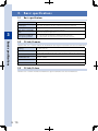
333 Basic specifications
3333
3
Basic specifications
Communication cycle
1ms
Control cycle
Min. 1ms/Max. 8ms
These values may depend on the robot configuration and controller configuration.
Max. number of robots
4 robots
Max. number of controllable
16 axes in total (including 4 axes of the master controller)
axes
Max. 12 axes only when using the slave
Option boards that can be
used for the YC-Link/E and
their operating conditions
Max. 3 PIO boards (This board cannot be installed in the slave controller.)
Max. 1 SIO board (This board cannot be installed in the slave controller.)
Max. 3 gripper boards (This board cannot be installed in the slave controller.)
Basic specifications
3333
YC-Link/E master
Only the RCX series controller with the YC-Link/E master board option installed becomes the YC-Link/E master.
Topology
Line (daisy chain) only
Data flow
Line: Flows from the master to the first slave and turns up after reached the last slave.
Communication media
Twist pair cable with braided using CAT5e or higher and double-shielded using the aluminum
tape
Communication rate
Full duplex, 100Mbit/s
Cycle time
Fixed at 1ms.
Synchronization
DC synchronization 1 using the Distributed Clock in the EtherCAT communication is supported.
3333
YC-Link/E slave
The RCX series controller with the YC-Link/E slave option installed becomes the YC-Link/E slave.
10
444 Operation
The YC-Link/E system is controlled with the master RCX series controller. In the YC-Link/E system, when the
master and slaves are turned on, the communication establishment process is performed automatically. After
the communication has been established, the robot can be operated.
For details about basic operating procedures, see the RCX series controller (RCX340) manual.
The following describes the YC-Link/E system specific operating procedures and cautions.
4444
About power-on timing
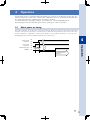
The master controller checks the slave connection at start-up. Therefore, turn on the slave power at the latest
until the control power to the master controller turns on. When the master and slave turn on at the same time,
it takes a long time to establish the communication, but this is not a problem. (For details, see section "4.2.1
LED lighting pattern of the YC-Link/E board (both slave and master)".)
Master controller
Control power
ON
Slave controller
Control power
ON
Dedicated output signal
MPREADY
ON
4
OFF
OFF
Operation
OFF
Min. 0 sec.
(5 sec. or longer are
recommended.)
(Max.) 1 min. or less
Communication between
the master and slave is
established.
11
4444
Checking the communication establishment between the master and slave
Use the procedures below to check the communication status among the controllers in the YC-Link/E system.
1. LED lighting pattern of the YC-Link/E boards (both the slave and master boards)
2. 7-segment LED display on the controller
3. Judgment by the dedicated output signal (MPREADY)
The following describes how to make the judgment by each procedure.
444444
LED lighting pattern of the YC-Link/E board (both slave and master)
■ ■ Master board
The RUN_LED and ERR_LED on the master board are lit at the same time immediately after the power has been turned on.
When the internal process has been completed, the RUN_LED starts flashing.
After that, when the slave presence is checked and the communication establishment preparation process is started, the
ERR_LED is off and the RUN_LED flashes repeatedly at a high speed at intervals of 50ms. The communication is not
established while the RUN_LED is flashing at intervals of 50ms.
Additionally, the LINK_LED flashes when the communication packet is sent between the master and slave.
4
Operation
When the communication is established, the RUN_LED is lit, the ERR_LED is off, and the LINK_LED flashes. In this case,
the master communicates with at least one slave correctly.
Even in this case, the LINK_LED flashes when the communication packet is sent between the master and slave.
■ ■ Slave board
The SYS_LED on the slave board is lit approximately 5 sec. after the power has been turned on.
If the SYS_LED is not lit, the controller may malfunction.
The ERR_LED starts flashing at about the same timing (uneven intervals). In this status, the communication with the
master can be started correctly.
When the communication starts correctly, the RUN_LED starts flashing at a high speed. After that, the RUN_LED flashes
at a low speed, and then it is lit when the connection is completed.
TIP
When both the master and slave controllers are turned on and the connection with the LAN cable is completed
before the ERR_LED on the slave flashes, the master board starts sending the communication packet.
However, the slave disposes of the packet that is sent in this status. The master that confirms this disposal performs
the re-connection process.
Therefore, when both the salve and master are turned on at the same time, it takes approximately 25 sec. to
complete the connection.
444444
7-segment LED display on the controller
The 7-segment LED on the master controller displays the emergency stop status, servo off, and return-to-origin
incomplete status until the communication with the slave is established. After the communication has been
established, the slave status is checked and the status of the overall system including the robot to be moved by
the slave is displayed.
The number "S.**" ("**" shows the set numeric value) that is set using the rotary switches on the slave board is
displayed and flashes on the 7-segment LED on the slave controller.
When the communication with the master is established, the flashing status changes to the lit status.
TIP
When the connection to the slave is failed, the master executes the connection retry process only once. [E19]
and [400] are alternately displayed on the 7-segment LED on the slave controller during retry process. When the
communication status has no problem, this means that the communication with the master is established.
444444
Judgment by the dedicated output signal (MPREADY)
MPREADY signal is provided at number SO04 of the SIO input/output used for the safety connector of the
master controller and the option board of the field network. When using the YC-Link/E, this signal is output as
the communication between the master and slave is established and the operation enters the servo on enable
status.
The host unit uses this signal to judge that the communication between the master and slave of the YC-Link/E
is established.
12
555 Troubleshooting
5555
Check items at YC-Link/E start-up
If the communication is not established or the robot cannot be controlled even after the YC-Link/E has been
started up while referring to the operating procedures stated in this manual, check the following items in
addition to the RCX series controller status.
1. How are the LEDs on the YC-Link/E board lighting?
2. Does any alarm occur?
3. Does the master communicate with all slaves?
The following shows each check item in detail.
111 How are the LEDs on the YC-Link/E board lighting?
Check the status and take corrective actions while referring to sections "4.2.1 LED lighting pattern of the YC-Link/E board
(both slave and master)" and "5.2 Meanings of LEDs on the YC-Link/E board".
222 Does any alarm occur?
An alarm may occur in the controller or an alarm unique to the YC-Link/E may occur.
Remove the cause of the trouble while referring to the RCX series controller manual and section "5.3 YC-Link/E related
alarms" in this manual.
333 Does the master communicate with all slaves?
1.The current position information of the robots connected to all slave controllers is updated.
2.The version information of all slave controllers is read-out.
13
Troubleshooting
Even when the number of slaves set in the master is different from the number of communication established slaves, the
YC-Link/E enters the communication establishment status. Therefore, even when the communication is established, the
master may not exchange the information with all slaves.
Use the programming box, PC application, or host unit and perform either procedure shown below to check that the
communications with all connected slaves are established.
5
5555
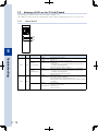
Meanings of LEDs on the YC-Link/E board
The following describes the LEDs on the YC-Link/E compatible unit.
These LEDs are used to check the communication status or take troubleshooting actions in case of an error.
555555
Master board
RUN
ERR
LINK
5
LED type
Troubleshooting
RUN
Color
Green
Lighting
Lit.
Meaning: Communicating with all slaves.
Corrective action: Operate as it is.
Flashing
(50ms intervals)
Meaning: Preparing the communication establishment
Corrective action: 1. Please wait.
2. If the ERR LED is lit, check the alarm and take corrective actions
according to the displayed alarm.
3.Turn off the power, and turn it on again.
Flashing
(200ms intervals)
Meaning: The power is turned on, but the communication is not established.
Corrective action: 1.I f the ERR LED is lit, check the alarm and take corrective actions
according to the displayed alarm.
2.Turn off the power, and turn it on again.
Lit.
ERR
Meaning: Corrective action:
Communication stops.
1.C heck that the slave is turned on.
2.C heck that the cables are connected correctly.
3.A fter checking 1. and 2. shown above, turn off the controller, and turn
it on again.
Meaning: Corrective action:
1.N o error occurs.
2.T he power is not turned on.
1.O perate as it is.
2.Turn on the power.
Red
Off
14
Meaning and corrective action
555555
Slave board
RUN
ERR
SYS
LED type
Color
Green
Green
and red
Lighting
Meaning and corrective action
Always lit.
Meaning: Normal status
Corrective action: Operate as it is.
Lit alternately.
Meaning: Failed to start up correctly.
Corrective action: 1.Turn off the controller, and turn it on again.
2.The controller may malfunction.
SYS
Meaning: Green
and red
Always lit
Off
Failed to start up correctly.
Corrective action: 1.Turn off the controller, and turn it on again.
2.The controller may malfunction.
Meaning: The slave board is not turned on.
Corrective action: 1.Check that the controller is turned on.
2.The controller may malfunction.
Meaning: Off
INIT status. The communication of the YC-Link/E is not
established.
Corrective action: If the status does not change after a while, check the
cable connections.
After that, turn off the master and turn it on again or make
the connections again.
Meaning: Flashing
(ON/OFF at even intervals)
RUN
Green
PRE-OPERATIONAL status. The communication of the
YC-Link/E is not established.
Corrective action: If the status does not change after a while, check the
cable connections.
After that, turn off the master and turn it on again or make
the connections again.
Meaning: Flash once
(Lit instantaneously.
Off time is long.)
SAFE-OPERATIONAL status. The communication of the
YC-Link/E is not established.
Corrective action: If the status does not change after a while, check the
cable connections.
After that, turn off the master and turn it on again or make
the connections again.
Meaning: Always lit.
OPERATIONAL status. The communication of the
YC-Link/E is establishing or has been established once.
Corrective action: If the communication is not established, check the ERR
LED status.
Off
Meaning: No error occurs.
Meaning: Flashing
(ON/OFF at even intervals)
ERR
Red
OPERATIONAL status. The communication of the
YC-Link/E is establishing or has been established once.
Corrective action: If the communication is not established, check the ERR
LED status.
Flash once.
(Lit instantaneously.
Off time is long.)
Meaning: OPERATIONAL status. The communication of the
YC-Link/E is establishing or has been established once.
Corrective action: If the communication is not established, check the ERR
LED status.
Flash twice.
(Lit instantaneously.
Off time is long.)
Meaning: Watch dog error occurs.
Corrective action: 1.Check the cable for faulty wiring.
2.Check that the master is turned on.
15
Troubleshooting
Red
5
5555
YC-Link/E related alarms
This section describes the error massages related to the YC-Link/E system.
19.400 :YC/E SLAVE CONNECTING RETRY
Code: &H0013 &H0190
Meaning/Cause
Corrective action
The YC-Link/E slave is retrying the connection establishment with the master.
Retrying the connection. Please wait.
19.500 :YC/E MASTER PORT OPEN FAIL
Code: &H0013 &H01F4
Meaning/Cause
The communication port of the YC-Link/E master board does not open within a certain period of
time (about 20sec.).
Corrective action
Check that the master and slave are connected with the cables. Check that the slave is turned
on.
19.501 :YC/E INITIALIZE FAIL
Code: &H0013 &H01F5
5
Meaning/Cause
Corrective action
The communication failed in the initialization process of the YC-Link/E connection.
Restart the controller.
Take noise preventive measures.
Replace the slave option board.
Troubleshooting
19.800 :YC/E SEND DATA CHECKSUM ERROR
Code: &H0013 &H0320
Meaning/Cause
Corrective action
The checksum error occurred in the data sent from the YC-Link/E master.
After taking noise preventive measures, reset the alarm.
Replace the controller.
19.801 :YC/E RECEIVE DATA CHECKSUM ERROR
Code: &H0013 &H0321
Meaning/Cause
Corrective action
The checksum error occurred in the data received by the YC-Link/E master. (Host check)
After taking noise preventive measures, reset the alarm.
Replace the controller.
19.802 :YC/E WORKING COUNTER ERROR
Code: &H0013 &H0322
Meaning/Cause
Corrective action
The YC-Link/E master could not send the data correctly. Or, the slave could not receive the
data correctly.
Replace the master board or slave board.
19.805 :YC/E MASTER RECEIVE CHECKSUM ERROR
Code: &H0013 &H0325
Meaning/Cause
Corrective action
16
The checksum error occurred in the data received by the YC-Link/E master. (Master check)
After taking noise preventive measures, reset the alarm.
Replace the controller.
19.900 :YC/E MASTER BOARD WATCHDOG ERROR
Code: &H0013 &H0384
Meaning/Cause
Corrective action
The data was not sent from the master board of the YC-Link/E for a certain period of time.
Check the LAN cable for disconnection.
Take noise preventive measures.
Replace the master board.
19.902 :YC/E MASTER DATA SEND FAIL
Code: &H0013 &H0386
Meaning/Cause
Corrective action
The master board of the YC-Link/E could not send the data for a certain period of time.
Check the LAN cable for disconnection.
Take noise preventive measures.
Replace the master board.
19.903 :YC/E MASTER DATA RECEIVE FAIL
Code: &H0013 &H0387
Meaning/Cause
Corrective action
The return of the data packet sent from the master board of the YC-Link/E could not received
for a certain period of time.
5
Check the LAN cable for disconnection.
Take noise preventive measures.
Replace the master board.
Code: &H0013 &H0388
Meaning/Cause
Corrective action
The return of the data packet sent from the master board of the YC-Link/E was different from its
sent status.
Take noise preventive measures.
Replace the master board.
19.905 :YC/E MASTER RECEIVE DATA DESTROY
Code: &H0013 &H0389
Meaning/Cause
Corrective action
The format of the data received by the master board of the YC-Link/E was faulty.
Take noise preventive measures.
Replace the master board.
19.906 :YC/E INVALID SLAVE EXIST
Code: &H0013 &H038A
Meaning/Cause
Corrective action
Slave that cannot be used exists in the slaves of the YC-Link/E.
Remove the inapplicable slave.
19.907 :YC/E SLAVE UNCONFORMITY
Code: &H0013 &H038B
Meaning/Cause
Corrective action
The controller hardware setting on the master controller of the YC-Link/E is different from that
on the slave controller.
Replace the controller.
19.908 :YC/E SLAVE CONFIG MISMATCH
Code: &H0013 &H038C
Meaning/Cause
The number of controllers set in the master of the YC-Link/E is different from the number of
actually connected controllers.
Corrective action
Change the parameter setting or turn off the power, and turn it on again after matching the
number of slaves to the setting.
17
Troubleshooting
19.904 :YC/E MASTER SEND DATA DESTROY
19.993 :YC/E MASTER UNKNOWN ERROR
Code: &H0013 &H03E1
Meaning/Cause
Corrective action
5
Troubleshooting
18
An unknown error occurred in the YC-Link/E.
Inform your distributor of the situation.
Revision record
Manual version Issue date
Ver. 1.00
Oct. 2014
Description
First edition
User’s Manual
YAMAHA CONTROLLER NETWORK
YC-Link/E
Oct. 2014
Ver. 1.00
This manual is based on Ver. 1.00 of Japanese manual.
YAMAHA MOTOR CO., LTD. IM Operations
All rights reserved. No part of this publication may be reproduced in
any form without the permission of YAMAHA MOTOR CO., LTD.
Information furnished by YAMAHA in this manual is believed to be
reliable. However, no responsibility is assumed for possible
inaccuracies or omissions. If you find any part unclear in this manual,
please contact your distributor.
IM Operations
882 Soude, Nakaku, Hamamatsu, Shizuoka, 435-0054, Japan
Tel. 81-53-460-6103 Fax. 81-53-460-6811
Robot manuals can be downloaded from our company website.
Please use the following for more detailed information.
http://global.yamaha-motor.com/business/robot/
YAMAHA MOTOR CO., LTD.