1
Controller Kit Installation Manual
MIFH1, MRCH1, MCCH1, MOS1
Installation guide for:
• Wireless Receiver and Cable (MIFH1)
• Portable Central Controller (MCCH1)
• Remote Controller (MRCH1)
• Outdoor Air Sensor (MOS1)
DISCONNECT POWER BEFORE BEGINNING INSTALLATION. Can cause
electrical shock or equipment damage.
Must be installed by a trained, experienced technician. Read these
instructions carefully. Failure to follow these instructions can damage the product or
cause a hazardous condition.
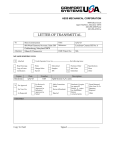
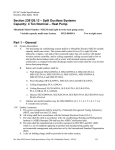
Installation at a glance
Wireless receiver
Remote controller
This document covers linking and
installation procedures for the
Mitsubishi Split-Zoning Ductless
and Ducted Systems' RedLINK™
control devices and accessories.
Wireless
outdoor
air sensor
Portable
central
controller
M32309
Before you begin, you must attach the cable to the CN105 connector on the indoor unit
control board, then follow the steps in this document.
Remote controllers are linked to specific indoor units. Each indoor unit must have a
dedicated remote controller and wireless receiver.
© 2010 Mitsubishi Electric & Electronics USA, Inc.
Suwanee, GA 30024 All Rights Reserved.
The three diamond logo is a registered trademark
of Mitsubishi Electric Corporation
www.mitsubishipro.com
69-2426-01
Wireless System Installation Guide
1 Install batteries in wireless devices
Install batteries in all devices. Make sure batteries are inserted properly (see polarity marks
on the devices).
Remote Controller
Install 2 fresh AA batteries
Install quick reference card
M28472A
M28474
Portable Central Controller (optional): Install 3 fresh AA batteries
Outdoor air sensor (optional): Install 2 fresh AA lithium batteries
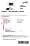
2 Install cable and receiver
1 Before mounting indoor unit, connect cable to
the 5-pin CN105 connector on the control board
in the indoor unit.
2 Mount indoor unit. Route cable to preferred
location of the wireless receiver.
3 Route cable through hole in base of wireless
receiver and attach to 5 pin connector on
receiver board.
4 Push the excess cable back through the indoor
unit or behind the wireless receiver. Do not cut
or modify the cable. Use zip tie connections on
back of receiver if needed.
5 Mount wireless receiver next to the indoor unit
(see below) or in a remote location.
Mount in the orientations shown. Do not block vents.
X
OR
OR
X
69-2426—01
MCR31400
2
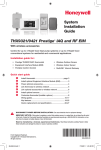
3 Link all devices to wireless network
1 Remove cover from wireless receiver.
2 Verify POWER light is solid green.
3 Press and release the CONNECT button.
4 If CONNECT light does not flash, another
receiver or RedLINK wireless adapter may be in
wireless setup mode. Exit wireless setup at the
other device.
POWER LED
CONNECT LED
Solid Green: Powered and communication
is established.
Flashing Green: In wireless setup
mode.
Slow Flashing Green (1 flash/
second): Receiver is powered.
Wait approximately 30 seconds for
communication to be established
between the wireless receiver and the
indoor unit. Check cable connection if
flashing does not stop after 30 seconds.
Solid Green: RedLINK communication
is established.
Yellow: Please wait.
Red: RedLINK device is not
communicating.
Flashing status light times out
after 15 minutes of inactivity. Press
CONNECT again if necessary.
Fast Flashing Green (5 flashes/second):
Error in communication between
wireless receiver and the indoor unit.
Check cable connection.
Link remote controller to wireless network
Zone name
Press s or t to change the name or location of this zone,
then press NEXT.
Example: 67 = Meeting Room
Wireless Setup
See complete zone list on page 8.
Next
M28925
Press CONNECT to establish a link to the wireless network.
If E0 or E1 appears, see error codes on page 10.
Wireless Setup
Connect
Back
M32308
Connected
After a brief pause, the confirmation screen at left should
be displayed to verify that the wireless connection has been
established.
Wireless Setup
Press DONE to display the home screen.
Done
M32307
3
69-2426—01
Wireless System Installation Guide
Link Portable Central Controller to RedLINK™ network (optional)
1 Make sure the CONNECT light on the
wireless receiver is flashing.
2 Press CONNECT at the Portable Central
Controller. There will be a short delay as the
Portable Central Controller seeks a signal
from the wireless network.
CONNECT
WIRELESS SETUP
3 When the screen displays "Connected,"
press DONE.
M28481
Press to link
another receiver
Press to save
and exit
4 Press NO at the next screen to save and exit.
(Or press YES and repeat steps 1-4 to link
another receiver.)
If E1 appears, see error codes on page 10.
YES
The linking procedure may time out if there is
no keypress within 15 minutes. To begin again,
press and hold the blank space (or arrow, if
present) in the lower right corner of the screen
until the display changes (about 3 seconds).
NO
CONNECT MORE?
M28482
Link outdoor sensor to RedLINK™ network (optional)
1 Make sure the CONNECT light on the
wireless receiver is flashing.
Press and release
2 Press and release the CONNECT button on the
back of the sensor.
3 Check remote controller to verify that the
outdoor sensor is working. After about
15 seconds, the remote controller should
display outdoor temperature and humidity.
M28483
69-2426—01
4
Exit wireless setup
Press and release the CONNECT button at the wireless receiver to exit wireless setup (light
should stop flashing and remain solid). Replace cover on wireless receiver.
Note: The wireless receiver will automatically exit wireless setup after 15 minutes
of inactivity.
Note: If installing more than one receiver, you must exit wireless setup before
installing remote controller and additional receiver.
4 Customize remote controller (installer setup)
Follow the steps below to begin installer setup. At each function screen, press s or t to
change the setting as desired, then press NEXT to advance to the next function screen.
See tables on pages 6-8 for a description of options for each function.
To begin, press and hold the FAN and s
buttons until the display changes. "WAIT"
will be displayed for up to 40 seconds.
Fan
M289871
Function
Setting
Press s or t to change
setting (see tables on pages
6-8).
Next
Done
Back
M28927
M28488A
Press DONE to save & exit.
5
Press NEXT to display next
function screen.
69-2426—01
Wireless System Installation Guide
Installer setup tables
Default settings for Setup functions 101-128 are automatically determined by the HVAC
equipment. It may take up to 40 seconds to enter setup, and 30 seconds to exit setup.
Setup function
101
103
104
105
107
108
109
110
111
115
117
123
124
125
127
128
Settings & options (factory default in bold)
1
2
3
Ventilation Air
1
2
3
Power Voltage
1
2
3
Auto energy-savings
1
operation
2
3
Change Filter Duration
1
2
3
Auto Fan (speed setting) 1
2
3
No. of Air Outlets (PLA
1
only)
2
3
High Performance Filter 1
Installed
2
3
Airflow Direction
1
Settings
2
3
Indoor Unit Coil Frost
1
Prevention Temperature 2
3
Defrost Control
1
2
3
Airflow Oscillate Mode
1
2
3
Heating Mode
1
Temperature Offset
2
3
Thermal Off Fan
1
Operation (Heat Mode)
2
3
Thermal Off Fan
1
Operation (Cool Mode)
2
3
Display System Error
1
2
3
Unit automatically
restarts after power
outage
69-2426—01
OFF
ON
Not Supported
Not Supported
IDU does not intake outdoor air through LOSSNAY
IDU does intake outdoor air through LOSSNAY
230V
208V
Not Supported
ON
OFF
Not Supported
100 Hours
2500 Hours
OFF
Quiet
Standard
High Ceiling
4 directions
3 directions
2 directions
NO
YES
Not Supported
No Vanes (or Vane #3 for PLA)
Vane #1 Setting (typically kept at the default setting)
Vane #2 Setting (typically kept at the default setting)
36 °F (2 °C)
37 °F (3 °C)
Not Supported
Standard
High Humidity
Not Supported
Not Available
Available
Not Supported
ON
OFF
Not Supported
Extra Low
Stop
Selectable Fan Speed
Selectable Fan Speed
Stop
Not Supported
ON
OFF
Not Supported
6
Installer setup tables
Setup function
Settings & options (factory default in bold)
134
Central Controller
(AG-150 or similar)
Present
0
1
Not Installed
Installed
136
Residential/Commercial
138
Permanent Hold Lock
(Non-programmable)
Fahrenheit/Celsius
Display
Commercial Override
Duration
1
0
0
1
0
1
3
0
1–12
0
1
1
0
2
3
3
2–8
0
1
0
1
1
0
0
1
0
1
2
0
1
0
1
0
1
Commercial
Residential
OFF (Programmable)
ON (Non-programmable)
Fahrenheit
Celsius
3 Hours
OFF
1–12 Hours
Heat & Cool (Heat Pump)
Cool Only
System Changeover (Auto, Heat, Off, Cool)
Manual Changeover (Heat, Off, Cool)
System Changeover Only (Auto Only)
System Changeover Single Setpoint - only with AG-150 or
similar (Auto, Heat, Off, Cool)
3 °F (2 °C)
2–8 °F (1.5–4.5 °C)
OFF
ON
5-2
5-1-1
ON
OFF
Not Shown
*See page 9 for feature information
Shown
Not Shown
Resume operation at next scheduled period
Permanently Off until user changes System mode
No
Yes
No
Yes
No
Yes
0
1
0
1
0
1
No
Yes
No
Yes
No
Yes
90
40–89
50
51–99
1
0
0
90 °F (32 °C)
* Subject to
40 to 89 °F (4.5 to 31.5 °C) HVAC Equipment
50 °F (10 °C)
* Subject to
51 to 99 °F (10.5 to 37 °C) HVAC Equipment
Sense at Remote Controller
Sense at Indoor Unit
0 °F (0 °C)
-3 to 3 °F (-1.5 to 1.5 °C)
139
140
142
System Type
144
System Changeover
145
System Changeover
Deadband Value
146
Drying Mode
148
Schedule Format
150
Optimal Start
152
Scheduled Off
154
Power Off Timer
("Sleep Timer")
160
Full Lockout
162
Lockout On/Off
164
165
Lockout System Mode
(Heat, Cool, Auto,
Drying)
Lockout Fan Mode
166
Lockout Setpoint
168
Lockout Set Clock/Day/
Schedule
170
Max Heat Setpoint
172
Min Cool Setpoint
173
Sensing Location
174
Indoor Temperature
Display Offset
7
69-2426—01
Wireless System Installation Guide
Installer setup tables
Setup function
Settings & options (factory default in bold)
176
0
178
Outdoor Temperature
Display Offset
Outdoor Humidity
Display Offset
192
Zone Name
194
Wireless Setup
198
Reset Schedule to
Factory Defaults
Reset Installer Setup to
Factory Defaults
199
69-2426—01
3
0
1
2
4
5
6
52
1
2
3
4
5
6
7
8
9
10
11
12
13
14
15
16
17
18
19
20
21
22
23
24
25
26
27
28
29
30
31
32
33
1
0
0
1
0
1
0 °F (0 °C)
-5 to 5 °F (-2.5 to 2.5 °C)
0%
-15%
-10%
-5%
5%
10%
15%
THERMOSTAT
34
MASTER BED
BASEMENT
35
MEDIA ROOM
BATHROOM
36
MUSIC ROOM
BATHROOM 1
37
NURSERY
BATHROOM 2
38
OFFICE
BATHROOM 3
39
OFFICE 1
BEDROOM
40
OFFICE 2
BEDROOM 1
41
PANTRY
BEDROOM 2
42
PLAYROOM
BEDROOM 3
43
POOL ROOM
BEDROOM 4
44
PORCH
BOAT HOUSE
45
REC ROOM
BONUS ROOM
46
SEWING ROOM
COMPUTER ROOM
47
SPA
DEN
48
STORAGE ROOM
DINING ROOM
49
STUDIO
EXERCISE ROOM
50
SUN ROOM
FAMILY ROOM
51
THEATER
FIREPLACE
52
THERMOSTAT
FOYER
53
UPPER LEVEL
GAME ROOM
54
UTILITY ROOM
GARAGE
55
WALK IN CLOSET
GREAT ROOM
56
WINE CELLAR
GUEST ROOM
57
WORKSHOP
GYM
Commercial Names
KID’S ROOM
64
CONFERENCE RM
KITCHEN
65
DRESSING ROOM
KITCHEN 1
66
MACHINE ROOM
KITCHEN 2
67
MEETING ROOM
LAUNDRY ROOM
68
OPEN AREA 1
LIBRARY
69
OPEN AREA 2
LIVING ROOM
70
SERVER 1
LOWER LEVEL
71
SERVER 2
MASTER BATH
72
STOCK ROOM
Remote controller is connected to wireless system
Disconnect Remote controller from wireless system
No
Yes
No
Yes
8
Special functions
Commercial Override (Setup Function 140): Allows an employee during an unoccupied period
to temporarily activate an occupied temperature. Each press of HOLD extends the occupied
temperature out 1 hour (or as installed).
Optimal Start (Setup Function 150): Allows the remote controller to “learn” how long the
equipment will take to reach programmed temperature settings, so the temperature is reached at
the scheduled time.
Scheduled Off (Setup Function 152): Allows the user to schedule a period where the split-zoning
system is completely off and resumes operation at the next scheduled period.
Power Off Timer (Setup Function 154): Allows user to schedule indoor unit completely off for one
instance:
Follow Schedule Option: indoor unit will resume operation at the next scheduled period.
Permanently Off Option: indoor unit will remain off indefinitely until the user changes the system
mode.
Installer test
Follow the procedure below to test for proper operation.
System test number
System status
Press s or t to
check system status
Press NEXT to
advance to next test
Next
M28488A
Done
Back
M32306
To begin, press and hold the s and t buttons
until the display changes (about 3 seconds).
System test
Press DONE to
terminate system test
System status
02 Wireless test
0
1
Off
Test radio signal (after a brief pause, screen displays 5-10 to show
signal strength; 5 or higher recommended)
50 Cool/Heat test
0
1
2
71
72
73
74
75
76
Off
Cool
Heat
Software revision number (major revisions)
Software revision number (minor revisions)
Configuration identification code (major)
Configuration identification code (minor)
Production configuration date code (week)
Production configuration date code (year)
80 Configuration Data 2
(remote controller)
81
82
83
Software revision number (major revisions)
Software revision number (minor revisions)
Software revision number (build revisions)
90 Configuration Data 1
(wireless receiver)
91
92
93
95
96
97
Software
Software
Software
Software
Software
Software
70 Configuration Data 1
(remote controller)
95 Configuration Data 2
(wireless receiver)
revision
revision
revision
revision
revision
revision
9
number
number
number
number
number
number
(major revisions)
(minor revisions)
(build revisions)
(major revisions)
(minor revisions)
(build revisions)
69-2426—01
Wireless System Installation Guide
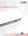
5 Mount remote controller & outdoor sensor
1 Separate the wallplate from the remote controller.
2 Mount the wallplate using the included screws and anchors 5 feet from the floor on
an interior wall. If the remote controller is configured to sense indoor temperature,
mount in the same room as the indoor unit.
Drill 3/16" holes for drywall.
Drill 7/32" holes for plaster.
3 Snap the remote controller to the wallplate on the wall.
Outdoor sensor (optional)
Mount the sensor on a vertical exterior wall, at least 6 inches below any
overhang. Choose a location protected from direct sunlight.
M28491
Place sensor securely
in bracket, facing
away from wall.
M28492
RedLINK™ error codes
E0 27 Verify device temperature is within operating range. If within range for at least 30
minutes and problem persists, replace Remote Controller.
E0 91 Communication was established between wireless receiver and the indoor unit,
but communication has been lost for 10 minutes. Check cable connection. Try
replacing the cable.
E1 29
Attempting to connect incompatible wireless devices.
E1 34
Low signal strength. Move wireless device to a different location and try again.
E1 38
Make sure Connect light on wireless receiver is flashing and you are 2+ feet away
from wireless receiver.
E1 54 Indoor unit does not support wireless receiver.
For full list of error codes, please refer to your equipment's technical service manual.
69-2426—01
10
Replacing system components
Note: Only use Mitsubishi Electric components or other designated components
for installation. Failure to comply may damage the product or cause a hazardous
condition.
Remote Controller
To replace a remote controller, install batteries and follow the procedures on page
3 to link it to the wireless network. If necessary, modify settings as needed (see
tables on pages 6–8).
Portable Central Controller & outdoor sensor
To replace a Portable Central Controller or outdoor air sensor, install batteries and
follow the procedures on page 4 to link it to the wireless network.
Wireless receiver
After installing a new wireless receiver, you must re-set the remote controller and
Portable Central Controller to communicate with the new equipment, as described
below.
At the remote controller:
1 Press and hold the FAN and s buttons for 3 seconds until display changes.
"WAIT" will be displayed for up to 17 seconds.
2 Press NEXT until Function 194 is displayed (wireless setup).
3 Press t to change Function 194 setting to 0 (disconnect from old wireless
receiver).
4 Follow the procedures on page 3 to link to new wireless receiver.
At the Portable Central Controller:
1 Press and hold the blank space (or arrow if
present) in the lower right corner of the screen
until the display changes (about 3 seconds).
2 Press REMOVE, then YES to disconnect from old
wireless receiver.
3 Follow the procedure on page 4 to link to new
wireless receiver.
Removing all wireless devices:
1 Press and hold the CONNECT button on the wireless receiver for 10 seconds.
2 To reconnect, see procedure on page 3.
11
69-2426—01
Regulatory information
FCC Compliance Statement (Part 15.19) (USA only)
This device complies with Part 15 of the FCC Rules. Operation is subject to the following two conditions:
1 This device may not cause harmful interference, and
2 This device must accept any interference received, including interference that may cause undesired operation.
FCC Warning (Part 15.21) (USA only)
Changes or modifications not expressly approved by the party responsible for compliance could void the user’s authority to
operate the equipment.
FCC Interference Statement (Part 15.105 (b)) (USA only)
This equipment has been tested and found to comply with the limits for a Class B digital device, pursuant to Part 15 of the
FCC Rules. These limits are designed to provide reasonable protection against harmful interference in a residential installation.
This equipment generates uses and can radiate radio frequency energy and, if not installed and used in accordance with the
instructions, may cause harmful interference to radio communications. However, there is no guarantee that interference will not
occur in a particular installation. If this equipment does cause harmful interference to radio or television reception, which can be
determined by turning the equipment off and on, the user is encouraged to try to correct the interference by one of the following
measures:
• Reorient or relocate the receiving antenna.
• Increase the separation between the equipment and receiver.
• Connect the equipment into an outlet on a circuit different from that to which the receiver is connected.
• Consult the dealer or an experienced radio/TV technician for help.
Wireless receiver, remote controller and outdoor sensor
To comply with FCC and Industry Canada RF exposure limits for general population/ uncontrolled exposure, the antenna(s) used
for these transmitters must be installed to provide a separation distance of at least 20 cm from all persons and must not be
co-located or operating in conjunction with any other antenna or transmitter.
Portable Central Controller
This portable transmitter with its antenna complies with FCC and Industry Canada RF exposure limits for general population/
uncontrolled exposure. This device must not be co-located or operating in conjunction with any other antenna or transmitter.
Section 7.1.5 of RSS-GEN
Operation is subject to the following two conditions:
1 this device may not cause interference, and
2 this device must accept any interference, including interference that may cause undesired operation of the device.
Specifications & replacement parts
Operating Ambient Temperature
Remote Controller: 32 to 120° F (0 to 48.9° C)
Portable Central Controller: 32 to 120° F (0 to
48.9° C)
Wireless receiver: -40 to 165° F (-40 to 73.9° C)
Outdoor air sensor: -40 to 140° F (-40 to 60° C)
Operating Relative Humidity
Remote Controller: 5% to 90% (noncondensing)
Portable Central Controller: 5% to 90% (noncondensing)
Wireless receiver: 5% to 95% (non-condensing)
Outdoor air sensor: 0% to 100% (condensing)
Physical Dimensions (height, width, depth)
Remote Controller: 3-9/16 x 5-13/16 x 1-1/2
inches (91 x 147 x 38 mm)
Wireless receiver: 6-7/16 x 3-1/4 x 1-5/16
inches (164 x 82.5 x 34 mm)
Outdoor air sensor: 5 x 3-1/2 x 1-11/16 inches
(127 x 89 x 43 mm)
Portable Central Controller: 6-1/4 x 3-1/8 x
1-5/8 inches (158.2 x 79.9 x 42 mm)
© 2010 Mitsubishi Electric & Electronics USA, Inc.
Suwanee, GA 30024 All Rights Reserved.
The three diamond logo is a registered trademark
of Mitsubishi Electric Corporation
69-2426—01 M.S. 11-10
Printed in U.S.A.
Accessories & Replacement Parts
Item
Part Number
Portable Central Controller
MCCH1
Outdoor air sensor
MOS1
Remote Controller
MRCH1
Receiver and Cable
MIFH1
Cable
MRC1