1
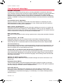
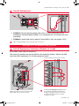
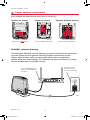
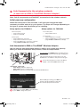
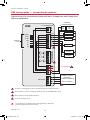
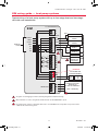
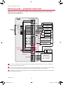
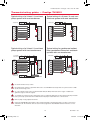
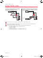
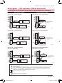
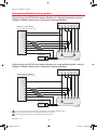
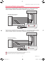
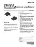
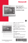
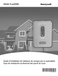
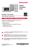
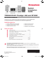
System
Installation
Guide
THX9321/9421 Prestige IAQ and RF EIM
®
With wireless accessories
Control for up to 4 Heat/2 Cool heat pump systems or up to 3 Heat/2 Cool
conventional systems for residential and commercial applications.
Installation guide for:
• Prestige THX9321/9421 thermostat
• Wireless Outdoor Sensor
• Equipment Interface Module (EIM)
• Wireless Indoor Sensor
• Portable Comfort Control
• RedLINK Internet Gateway
™
Quick start guide
1
Install thermostat...........................................................page 3
2
Install optional Equipment Interface Module (EIM)................. 3
3
Power optional accessories.................................................... 4
4
Link thermostat to wireless network....................................... 5
5
Link optional accessories to wireless network....................... 6
6
Install optional sensors........................................................... 7
7
Customize thermostat (installer options)................................ 8
Wiring guides...................................................................10-17
Key features.....................................................................18-25
Device replacement and specifications...........................26-27
DISCONNECT POWER BEFORE INSTALLATION. Can cause electrical shock or equipment damage.
MERCURY NOTICE: If this product is replacing a control that contains mercury in a sealed tube, do not place the old control
in the trash. Contact the Thermostat Recycling Corporation at www.thermostat-recycle.org or 800-238-8192 for information on how
and where to properly and safely dispose of your old thermostat.
Must be installed by a trained, experienced technician. Read these instructions carefully. Failure to follow
these instructions can damage the product or cause a hazardous condition.
® U.S. Registered Trademark.
Copyright © 2011 Honeywell International Inc.
All rights reserved.
69-2490_B.indd 1
69-2490-03
7/13/2011 1:41:45 PM
System Installation Guide
Your Honeywell advantage
RedLINK™ Compatible
Increase your content and profit per job by including RedLINK™ accessories that meet
your customers comfort and convenience needs. RedLINK accessories include the Wireless
Outdoor Sensor, Portable Comfort Control (PCC), Equipment Interface Module (EIM),
RedLINK Internet Gateway, Wireless Indoor Sensor, TrueSTEAM™ humidifier with Wireless
Adapter, TrueZONE™ zoning panel with Wireless Adapter, Vent Boost Remote and Wireless
Remote.
Customizable Service Reminders
Set up to 10 service reminders. Choose from the pre-set options or customize your own.
Reminders based on date, outdoor temperature or a dry contact input will alert customers
with instructions to contact you for assistance.
Delta T Alerts and Diagnostics
Alerts give customers a sense of security while also enabling you to service or replace the
equipment prior to a loss of heating or cooling. Based on limits you set at installation, customers can be alerted when their system is not operating as expected. The system alert will
instruct customers to contact you for assistance. Requires EIM.
Delta T Installer Test
Save time by viewing Delta T while running a system test to verify proper operation. Requires
EIM.
Universal Inputs – S1 and S2
Assignable inputs allow you to configure Indoor and Outdoor Temperature Sensors,
Discharge and Return Air Sensors or Dry Contact Devices. Dry Contact Devices can be
used to trip pre-set or customized alerts on the thermostat home screen. Requires EIM.
User Interaction Log
The interaction log stores history of thermostat setting changes including temperature, system and installer setup. You can use the interaction log to save time by determining if the
issue is a system error or an accidental user error.
Configurable for Residential and Light Commercial Applications
One thermostat does it all to meet the needs of Residential and Light Commercial applications. Simply select Residential or Commercial during the installer setup. If Commercial is
selected, the thermostat will use commercial language, meet building codes and offer 365
day holiday scheduling.
USB Port for Quick Installer Setup
Save time by using a USB stick to upload installer settings and service reminders in one
simple step.
Equipment Setup Wizard
The thermostat installer uses plain language and simple questions to guide you through
the set-up process. Settings are automatically modified according to the type of equipment
selected, helping to eliminate common installation errors.
Selectable Sensors
When paired with a Wireless Indoor Sensor(s) you have the ability to choose which
sensor(s) to use for temperature, humidification and dehumidification. They can be used
in combination for temperature averaging—or individually—to condition humidity levels in
separate spaces.
69-2490—03
69-2490_B.indd 2
2
7/13/2011 1:41:45 PM
THX9321/9421 Prestige IAQ and RF EIM
®
1
Install thermostat
MCR29241
MCR32386
MCR32387
• THX9421: Mount the thermostat and wire to C and R terminals of the
Equipment Interface Module (EIM), or to a separate 24 volt transformer (not
provided).
• THX9321: Install and wire as above if using EIM. If not, see pages 13-15.
When used with the EIM, the relays in the thermostat do not function.
See pages 10-17 for detailed wiring guidelines
2
Install Equipment Interface Module (if used)
[If no EIM is used, skip to Section 3.]
Use screws & anchors as appropriate for the mounting surface. Mount the EIM
near the HVAC equipment, or on the equipment itself.
Strip 1/4” insulation, then insert wires as shown.
R
W3 W2 W
AUX2AUX1 O/B
C
Y
Y2
G
L
MCR32389
MCR32388
If installing a discharge/return air sensor, it must
be located between the IAQ equipment and the
heating/cooling equipment. The sensors must be
in air that is mixed well (away from a-coil/heat
exchanger). See page 7.
NOTE: If you install more than one thermostat and
EIM, the EIMs must be at least 2 feet apart.
3
69-2490_B.indd 3
69-2490—03
7/13/2011 1:41:48 PM
System Installation Guide
3
Power optional accessories
[If no wireless accessories are used, skip to Section 4.]
Outdoor air sensor
Indoor air sensor
MCR32938
MCR32937
Install 2 fresh AA lithium batteries
Install 2 fresh AAA alkaline batteries
Portable Comfort Control
MCR32939
Install 3 fresh AA alkaline batteries
RedLINK™ Internet Gateway
The Honeywell RedLINK Internet Gateway gives your customers remote access
to home climate-control systems from any location with Internet access.
Using a Web browser, users can review and adjust indoor temperature,
system mode and other settings. The Gateway can also send alerts to as many
as 6 email addresses if a problem occurs.
Connect power cord to
an electrical outlet not
controlled by a wall switch
Connect RedLINK Gateway to a
router or modem with Ethernet
cable (RJ45).
M32940
69-2490—03
69-2490_B.indd 4
4
7/13/2011 1:41:49 PM
THX9321/9421 Prestige IAQ and RF EIM
®
4
Link thermostat to the wireless network
(if used with an EIM or TrueZONE Wireless Adapter)
Next, link all components and RedLINK accessories to the wireless network.
™
Initial powerup configuration
When the thermostat is first activated, it will lead you through the steps
necessary to define and set up your system. The steps will change depending on
the type of system and thermostat you're installing.
Setup options for THX9321
Setup options for THX9421
If non-zoned system:
• Setup for thermostat only
• Setup for use with EIM
If non-zoned system:
• Setup for EIM connection
If zoned system:
• Setup for EIM wired to zone panel
• Setup for RedLINK wireless connection to zone panel
(using THM4000 TrueZONE Wireless Adapter)
If zoned system:
• Setup for EIM wired to zone panel
• Setup for thermostat wired to zone panel
• Setup for RedLINK wireless connection to zone panel
(using THM4000 TrueZONE Wireless Adapter)
Link thermostat to EIM or TrueZONE Wireless Adapter
®
Use the step-by-step thermostat menus to define your system type (above).
When you reach the Wireless Setup screen, follow the steps below:
Press and release the CONNECT button at the EIM or Wireless
Adapter, and make sure the "Connected" light is flashing green.
CONNEC
CONNEC
TED
T
S2
S2
S1
S1
If the "Connected" light does not flash, make sure no other
RedLINK devices are in Wireless Setup mode, then try again.
If the "Connected" light does not flash on the Wireless
Adapter, consult the TrueZONE manual for help.
MCR32941
"Connected" status light
• Green flashing: In Wireless Setup mode.
• Green steady: System is working normally.
• Red: Wireless device(s) not communicating. Check EIM and RedLINK devices.
While the EIM light is flashing, press NEXT to link
the thermostat with the EIM. After a brief delay,
the screen will display "Device Connected."
At any screen you can press HELP for more information,
or press BACK to change earlier options.
5
69-2490_B.indd 5
69-2490—03
7/13/2011 1:41:50 PM
System Installation Guide
5
Link optional accessories to wireless network
While the Add Device screen is displayed
on the thermostat, press and release the
CONNECT button on each wireless device, as
described below. Accessories need to be at
least 2 feet away from the thermostat or EIM
during the linking process.
Press DONE after all devices have been linked
Wireless outdoor sensor
Wireless indoor sensor
MCR32934
MCR32935
MCR28847A
Press and release CONNECT. After
a short delay the thermostat will
display outdoor temperature and
humidity.
Press and release CONNECT.
After a short delay, the status light
will glow green for 15 seconds.
If the status light turns red,
the sensor did not link with the
thermostat.
In normal operation, this light
remains off. If it begins flashing
red, batteries are low (power will
be depleted after 3 weeks).
Portable Comfort Control
Press CONNECT on the Portable Comfort Control display screen. Press DONE when the
screen displays "Connected," then exit or continue to link another thermostat.
CONNECT
WIRELESS SETUP
Error messages:
E1 29 Incompatible device cannot be connected.
E1 34 Low RF signal. Move device to a different location and try again.
E1 38 Make sure the thermostat or the EIM is in Wireless Setup mode,
and the Portable Comfort Control is at least 2 feet away (600 mm).
MCR32942
The linking procedure will time out if there is no keypress for 30 minutes. To begin again,
press and hold the blank space in the lower right corner of the screen (an arrow may
appear here). Hold until the display changes (about 3 seconds).
RedLINK Internet Gateway
Press and release the button on the bottom of the Internet
Gateway. After a short delay, the RedLINK status light will glow
steady green.
MCR32943
69-2490—03
69-2490_B.indd 6
The Internet Gateway must be registered online before
use at www.mytotalconnectcomfort.com. Enter the MAC
ID and MAC CRC numbers located on the bottom of
the Internet Gateway. For additional information, see
instructions provided with the device.
6
7/13/2011 1:41:51 PM
THX9321/9421 Prestige IAQ and RF EIM
®
6
Install optional sensors
[If no sensors are used, skip to Section 7.]
To install outdoor air sensor
1 Mount the sensor on a vertical
exterior wall, at least 6 inches below
any overhang. Choose a location
protected from direct sunlight.
2 Place sensor securely in bracket,
facing away from wall.
M28491
M28849A
To install indoor air sensor
1 Remove the wallplate and mount it 4
to 6 feet above the floor on an interior
wall. Drill 3/16-inch holes for drywall,
7/32-inch for plaster.
2 Attach sensor securely to wallplate as
shown.
M32936
To install discharge/return air sensor
1 Install the sensor between the IAQ
equipment and the heating/cooling
equipment. The sensors must be in air
that is mixed well (away from a-coil/
heat exchanger).
M32995
2 Drill 1/4-inch hole for the sensor
probe and mount it to the ductwork
with enclosed screws.
3 Connect wires to S1 or S2 terminals at
the EIM.
7
69-2490_B.indd 7
69-2490—03
7/13/2011 1:41:52 PM
System Installation Guide
7
Setup Installer options (ISU)
To configure the thermostat, press MENU > INSTALLER OPTIONS, then enter date
code when prompted (printed on back of thermostat). Or press MENU > EQUIPMENT
STATUS to find the date code.
A brief summary of installer options follows. You can download a complete list of
all options at http://customer.honeywell.com.
Press CREATE SETUP to set all system
settings one by one.
Press VIEW/EDIT to select a specific
function and make quick changes.
TIP: You can use the thermostat USB port to download all system configuration and installer options, including your company
name and contact information. You can upload this data to each thermostat you install, to save time.
R: Residential C: Commercial B: Both
ISU
Function
1000Language
1010Residential/Commercial
1020
Zone Number
1030
Device Name
1030
Device Name on Home Screen
1040Programmable/Non-programmable
1050Fahrenheit/Celsius
1060
Outdoor Air Sensor
2000
Heating System Type
2010
Heating Equipment Type
2020-2100 Heat Stages
2050
Geothermal Forced Air System
2060
Reversing Valve O/B
2070-2090 Cool/Compressor Stages
2110
Fan Operation in Heat
2120, 2180 Backup Heat Type
2130, 2170 Backup Heat Stages
2150, 2200 Backup Heat Operation
2160, 2210 Backup Heat Fan Operation
2190
External Fossil Fuel Kit
2220
L/A Terminal Setup
3000
Manual/Auto Changeover
3000
Auto Changeover Deadband
3010
Temperature Control Options
3020
Finish With High Cool Stage
3021
Finish With High Heat Stage
3030
Staging Control - Cool Differentials
3040-3060 Staging Control - Heat Differentials
3070
Balance Point Only or Differential
3080, 3090 Staging Control - Backup Heat Differentials
3110
Backup Heat Upstage Timer
3120
Outdoor Compressor Lockout
3120
Outdoor Backup Heat Lockout
3130, 3150 Heat Cycles Per Hour
3140
Cool Cycles Per Hour
3160
Backup Heat Cycles Per Hour
69-2490—03
69-2490_B.indd 8
Thermostat functions marked in gray below require an EIM (see page 3).
B
B
B
B
C
B
B
B
B
B
B
B
B
B
B
B
B
B
B
B
C
B
B
B
B
B
B
B
B
B
B
B
B
B
B
B
ISU
Function
3170-3190
3200-3220
3240
3260
3260
4000
4010
4020
4030
4050
4060
4070
4080
4090
4100
4100
4110
4120
Cooling Derivative, Integral, Throttling range
Heating Derivative, Integral, Throttling range
Minimum Compressor Off Time
Extended Fan Run Time in Cool
Extended Fan Run Time in Heat
Number of Scheduled Periods
Pre-occupancy Purge Duration
Override: Standard or Initiate Occupancy
Override Duration
Minimum Recovery Settings - Heat
Maximum Recovery Settings - Heat
Minimum Recovery Settings - Cool
Maximum Recovery Settings - Cool
Adaptive Intelligent Recovery
Minimum Cool Setpoint
Maximum Heat Setpoint
Keypad Lockout
Wireless Remote* Home/Occupied Cool Setpoint
Wireless Remote* Home/Occupied Heat Setpoint
Wireless Remote* Away/Unoccupied Cool Setpoint
Wireless Remote* Away/Unoccupied Heat Setpoint
Wireless Remote* Vacation/Holiday Cool Setpoint
Wireless Remote* Vacation/Holiday Heat Setpoint
Select Wired Sensors
Indoor Temperature Sensor Name
Terminals Wired to Indoor Sensor
Indoor Temperature Sensor Type
Indoor Sensors Used for Temperature Control
Terminals Wired to Outdoor Sensor
Terminals Wired to Return Air Sensor
4120
4130
4130
4140
4140
5000
5010
5020
5030
5040
5050
5070
C
C
B
B
B
B
C
C
C
C
C
C
C
R
B
B
B
B
B
B
B
B
B
B
B
B
B
B
B
B
8 * Wireless Remote - coming soon.
7/13/2011 1:41:52 PM
THX9321/9421 Prestige IAQ and RF EIM
®
7
Installer options (ISU)
Thermostat functions marked in gray below require an EIM (see page 3).
ISU
Function
ISU
5080
5090
5100
5110
6000
6010
6020
6030
6040
6040
6050
Return Air Sensor Type
B
Terminals Wired to Discharge Air Sensor
B
Discharge Air Sensor Type
B
A-Coil Low Temperature Cutoff
B
Select the Dry Contacts in the System
B
Terminals Wired to Remote Setback Dry ContactC
Remote Setback Dry Contact Setup
C
Remote Setback Time Delay
C
Remote Setback - Standby Cool Setpoint
C
Remote Setback - Standby Heat Setpoint
C
Terminals Wired to Full Drain Pan Alert
Dry Contact
B
6060
Full Drain Pan Alert Dry Contact Setup
B
6070
Terminals Wired to Dirty Filter Alert Dry ContactB
6080
Dirty Filter Alert Dry Contact Setup
B
6090
Terminals Wired to Water Leak Alert Dry ContactB
6100
Water Leak Alert Dry Contact Setup
B
6110
Terminals Wired to System Shutdown
Alert Dry Contact
C
6120
System Shutdown Alert Dry Contact Setup
C
6130
Terminals Wired to Service Needed
Alert Dry Contact
B
6140
Service Needed Alert Dry Contact Setup
B
6150
Terminals Wired to Fan Failure Alert Dry ContactC
6160
Fan Failure Alert Dry Contact Setup
C
6170
Terminals Wired to Custom Alert Dry Contact B
6180
Custom Alert Dry Contact Setup
B
6190, 6200 Custom Alert Name and Message
B
7000
Filter Type
B
7020
Number of Air Filters
B
7110
Air Filter Replacement Reminder
B
7110
Air Filter 2 Replacement Reminder
B
7120
EAC Cell Cleaning Reminder
B
7120
EAC Pre-Filter Cleaning Reminder
B
7120
EAC Post-Filter Replacement Reminder
B
8000
Humidifier Type
B
8010
Indoor Sensor Used for Humidification Control B
8030
Terminals Wired to the Humidifier
B
8050
Humidification - Window Protection
B
8060
System Modes Allowing Humidification
B
8070
Humidification Control
B
8080
Humidifier Lockout
B
8100
Clean Tank / Water Filter Replacement ReminderB
8100
Humidifier Pad Replacement Reminder
B
9000
Dehumidification Equipment
B
9010
Indoor Sensor Used for Dehumidification Control B
9020
Humidity Sensor Displayed on the Home Screen B
9040
Terminals Wired to Dehumidification Equipment B
9050
A/C with Low Speed Fan Setup
B
9050
Hot Gas Bypass Setup
C
9070
Dehumidification - Overcooling Limit
R
9080
Dehumidification Control
C
9090
Dehumidification Minimum On Time
C
9100
High Humidity Comfort Reset Setting
C
9110
Dehumidification High Limit Range Stop
C
9120
9130
9140
9180
9190
9200
System Modes Allowing Dehumidification
B
Dehumidifier Fan Control
B
Dehumidifier Lockout
B
Dehumidification Away Mode
B
Dehumidification Away Mode - Fan Control
B
Dehumidification Away Mode Low Limit Temperature
B
9200
Dehumidification Away Mode Temperature Setting
B
9200
Dehumidification Away Mode Dehumidification Setting
B
9210
Dehumidifier Filter Replacement Reminder
B
10000
Ventilation Type
B
10020
Terminals Wired to Ventilator/Fresh Air Damper B
10050
Ventilation Control Method
B
10060
Ventilation Fan Control
B
10090
Number of Bedrooms
R
10090
Size of House
R
10100
Ventilation Level (CFM)
R
10120
Ventilation Percent On Time
B
10130
Ventilation Low Temperature Lockout
B
10130
Ventilation High Temperature Lockout
B
10130
Ventilation High Dewpoint Lockout
B
10140
Lockout Ventilation on Hum/Dehum Calls
B
10160
Ventilate on High Indoor Humidity
B
10170
Ventilator Core Cleaning Reminder
B
10170
Ventilator Filter Cleaning Reminder
B
11000
Number of UV Devices
B
11050
UV Bulb Replacement Reminder
B
11050
UV Bulb 2 Replacement Reminder
B
12000
Installer Custom Reminders
B
13000
Heat Delta T Diagnostics
B
13010
Cool Delta T Diagnostics
B
13015
Set Advanced Delta T Diagnostic Options
B
13020
Allow Delta T Diagnostics During HumidificationB
13030
Allow Delta T Diagnostics During
Dehumidification
B
13040
Allow Delta T Diagnostics During Ventilation
B
13050-13080Allow Heat Delta T Diagnostics:
Temp & Humidity
B
13090-13120Allow Backup Heat Delta T Diagnostics:
Temp & Humidity
B
13130-13160Allow Cool Delta T Diagnostics:
Temp & Humidity
B
13170
Defrost Cycle
B
13180
Delta T Fault Sensitivity
B
13190
Display Delta T Alerts to Homeowner
B
14000
Clock Format
B
14010
Daylight Saving Time
B
14020
Indoor Temperature Display Offset
B
14020
Indoor Humidity Display Offset
B
15000-15020Dealer name, phone, email, website, message B
9
69-2490_B.indd 9
Function
69-2490—03
7/13/2011 1:41:53 PM
System Installation Guide
EIM wiring guide — conventional systems
Typical wiring of a conventional system with up to 3-stage heat and 2-stage cool
with one transformer.
EIM
TO THERMOSTAT
24
C VAC
CONV
POWER
HEAT
COOL
STATUS
LEDS
R
FURNACE
TRANSFORMER
HEAT STAGE 1
W
HEAT STAGE 2
W2
W3
FAN
U1
U2
U3
120
VAC
HEAT STAGE 3
G
FAN
A 4
Y COMPRESSOR
STAGE 1
Y2 COMPRESSOR
STAGE 2
1
JUMPERS 3
SENSORS
CONNECT OPTIONAL
SENSORS TO
S1 AND S2 TERMINALS
(MAX. 2 SENSORS)
2
1
See guides on following pages for thermostat wiring and geothermal radiant heat wiring.
2
Wire a maximum of 2 sensors using the S1 and S2 terminals. See ISU 5000-6190 for options.
3
Remove jumper(s) if using separate transformers.
4
See Economizer wiring section.
MCR32945
See following pages for additional thermostat wiring guidlines for heat pumps,
geothermal systems and optional Economizer.
69-2490—03
69-2490_B.indd 10
10
7/13/2011 1:41:54 PM
THX9321/9421 Prestige IAQ and RF EIM
®
EIM wiring guide — heat pump systems
Typical wiring of a heat pump system with up to four-stage heat and two-stage
cool with one transformer.
EIM
TO THERMOSTAT
O/B
HEAT PUMP
O/B
POWER
HEAT
STATUS
LEDS
BACKUP HEAT
STAGE 1
AUX1
AUX1
COOL
FAN
U1
U2
U3
CHANGEOVER VALVE
BACKUP HEAT
STAGE 2
AUX2
AUX2
Y COMPRESSOR
STAGE 1
L/A
3
1
Y2 COMPRESSOR
STAGE 2
G
FAN RELAY
L/A
COMPRESSOR
MONITOR OR
3
ZONE PANEL
JUMPERS
R
C
AIR HANDLER
TRANSFORMER
24
VAC
120
VAC
2
SENSORS
CONNECT OPTIONAL
SENSORS TO
S1 AND S2 TERMINALS
(MAX. 2 SENSORS)
2
MCR32946
1
See guides on following pages for thermostat wiring and geothermal radiant heat wiring.
2
Wire a maximum of 2 sensors using the S1 and S2 terminals. See ISU 5000-6190 for options.
3
L/A terminal sends continuous output when thermostat is set to EM HEAT mode, except when set up for Economizer
or TOD. See Economizer wiring section.
11
69-2490_B.indd 11
69-2490—03
7/13/2011 1:41:54 PM
System Installation Guide
EIM wiring guide — geothermal radiant heat
Typical wiring for geothermal radiant heat, geothermal forced-air, and backup
heat with one transformer.
EIM
TO THERMOSTAT
O/B
HEAT PUMP
STATUS
LEDS
O/B
POWER
HEAT
COOL
FAN
U1
U2
U3
AUX1
AUX2
CHANGEOVER VALVE
BACKUP HEAT
STAGE 1
AUX1
BACKUP HEAT
STAGE 2
AUX2
COMPRESSOR Y
STAGE 1
L/A
3
COMPRESSOR Y2
STAGE 2
G
FAN RELAY
L
COMPRESSOR MONITOR
OR ZONE PANEL
3
GEOTHERMAL RADIANT
HEAT STAGE 1
1
OPTIONAL
JUMPER
R
2
C
AIR HANDLER
TRANSFORMER
24
VAC
120
VAC
2
JUMPERS
CONNECT OPTIONAL
SENSORS TO
S1 AND S2 TERMINALS
SENSORS
(MAX. 2 SENSORS)
MCR32947
1
U1, U2 or U3 terminals must be used for geothermal radiant heat (ISU 2010). Thermostat allows 2 stages of radiant heat—
geothermal (stage 1) and boiler (stage 2).
2
“U” terminals are normally open dry contacts when set up for geothermal radiant heat. You must install a field jumper if radiant
heat is powered by system transformer. Do NOT install a field jumper if radiant heat has its own transformer.
3
L/A terminal sends continuous output when thermostat is set to EM HEAT mode except when set up for Economizer or TOD.
See Economizer wiring section.
69-2490—03
69-2490_B.indd 12
12
7/13/2011 1:41:55 PM
THX9321/9421 Prestige IAQ and RF EIM
®
Thermostat wiring guides — Prestige THX9321
Typical wiring of a 3-heat / 2-cool heat
pump system with one transformer
Transformer
24
VAC
Transformer
C
R
HEAT STAGE 2
Y
COMPRESSOR STAGE 1
U1
Y2
COMPRESSOR STAGE 2
U1
G
FAN RELAY
Y
COMPRESSOR STAGE 1
R
Y2
COMPRESSOR STAGE 2
G
FAN RELAY
L/A
COMPRESSOR MONITOR
OR ZONE PANEL
6
U2
6
MCR32948
Typical wiring of a 3-heat / 2-cool heat
pump system with two transformers
24
VAC
COMPRESSOR STAGE 1
Y2
COMPRESSOR STAGE 2
G
L/A
6
K
1
Rc
3
U2
O/B
AUX/E
120
VAC
24
VAC
C
BACKUP HEAT
Rc
Y2
COMPRESSOR STAGE 2
FAN RELAY
U1
G
FAN RELAY
COMPRESSOR MONITOR
OR ZONE PANEL
U2
L/A
COMPRESSOR MONITOR
OR ZONE PANEL
1
U2
120
VAC
24
VAC
R
C
6
BACKUP HEAT
K
C
R
CHANGEOVER VALVE
U1
2
U2
MCR32949
COMPRESSOR STAGE 1
R
U1
1
Y
Backup Heat
Transformer
U1
2
R
4
Thermostat
C
CHANGEOVER VALVE
R
K
Transformer
C
R
AUX/E
Y
Rc
5
Typical wiring for geothermal radiant
heat, geothermal forced-air and backup heat with one transformer
Thermostat
O/B
120
VAC
C
A
2
Air Handler
Transformer
C
R
Thermostat
HEAT STAGE 1
Rc
K
24
VAC
W
C
BACKUP HEAT
1
120
VAC
W2
CHANGEOVER VALVE
AUX/E
Thermostat
O/B
120
VAC
Typical wiring of a 2-heat / 2-cool conventional system with one transformer
U1
GEOTHERMAL
RADIANT
HEAT
STAGE 1
U1
U2
3
U2
MCR32951
MCR32950
1
U1 and U2 terminals are dry contacts.
2
L/A terminal sends continuous output when thermostat is set to EM HEAT mode except when set up for Economizer or TOD.
See Economizer wiring section.
3
U1 or U2 terminals must be used for geothermal radiant heat (ISU 2010). Thermostat allows 2 stages of radiant heat—
geothermal (stage 1) and boiler (stage 2).
4
"U" terminals are normally open dry contacts when set up for geothermal radiant heat. You must install a field jumper if radiant
heat is powered by system transformer. Do NOT install a field jumper if radiant heat has its own transformer.
5
Remove jumper if using separate transformers.
6
Connect the THP9045 Wiresaver Module to the K terminal in heating/cooling applications that do not have a common wire
at the thermostat. The K terminal cannot be used in heat-only applications. See THP9045 installation instructions for more
information.
13
69-2490_B.indd 13
69-2490—03
7/13/2011 1:41:56 PM
System Installation Guide
Prestige THX9321 or EIM:
Using universal relays to control heating or cooling
Powering universal relay with system
transformer (THX9321 shown)
Transformer
120
VAC
24
VAC
Transformer
C
R
Rc
2
R
24
VAC
C
R
C
Rc
2
1
HEAT STAGE 3
U2
U2
R
U1
U1
U1
Thermostat
C
HEAT STAGE 3 or
COOL STAGE 3 or
COOL STAGE 4
120
VAC
Thermostat
3
Powering universal relay with separate
heating transformer (THX9321 shown)
Transformer
1
120
VAC
R
24
VAC C
3
1
U1
U2
1
U2
MCR32953
MCR32952
1
U1/U2/U3 terminals are normally open dry contacts when set up for a stage of heating or cooling.
2
You must install a field jumper if the stage of heating or cooling is powered by system transformer. Do NOT install a field
jumper if the stage of heating has its own transformer.
3
U1/U2/U3 terminals are assigned to a stage of heating or cooling in the Installer Setup. Options are:
• Heat -- Stage 3 (last stage of heating) -- ISU 2100, 2140, or 2170
• Cool: Stage 3 -- ISU 2080
• Cool: Stage 4 -- ISU 2090
• Geothermal radiant heat: Stage 1 -- (see wiring guide on pages 12-13)
• Geothermal radiant heat: Stage 2 -- (see wiring guide on pages 12-13)
69-2490—03
69-2490_B.indd 14
14
7/13/2011 1:41:57 PM
THX9321/9421 Prestige IAQ and RF EIM
®
Wiring guide — IAQ equipment (EIM or thermostat)
"U" terminals can be used for humidification, dehumidification or ventilation.
With power supply
Without power supply
Typical hookup of powered humidifier.
Typical hookup of non-powered humidifier.
U3
U3
U3
U2
U3
U2
U2
U2
U1
POWERED
HUMIDIFIER
U1
24
VAC
U1
RH
FIELD INSTALLED
JUMPER BETWEEN
R AND U1
RH
RC
24
VAC
NON-POWERED
HUMIDIFIER
U1
120
VAC
RC
24
VAC
R
C
120
VAC
24 VAC
M32393
R
120
VAC
24
VAC
C
M32394
Typical hookup of powered ventilation.
Typical hookup of non-powered ventilation.
U3
U3
U3
U2
U3
U2
U2
U2
U1
POWERED
VENTILATOR
U1
24
VAC
U1
RH
FIELD INSTALLED
JUMPER BETWEEN
R AND U1
RH
RC
24
VAC
NON-POWERED
VENTILATOR
U1
120
VAC
RC
R
24
VAC
C
120
VAC
24 VAC
R
24
VAC
C
120
VAC
M32396
M32397
Typical hookup of powered dehumidifier
(whole house dehumidifier).
Typical hookup of variable speed blower for
dehumidification in low speed.
U3
U3
U3
U2
U3
U2
U2
U2
U1
U1
POWERED
DEHUMIDIFIER
U1
24
VAC
120
VAC
OR
RH
2
DEHUMIDIFICATION
WITH LOW SPEED FAN
U1
FIELD INSTALLED
JUMPER BETWEEN
R AND U1
RH
RC
24
VAC
1
RC
R
24
VAC
C
120
VAC
24 VAC
M32398
R
C
24
VAC
120
VAC
M32392
KEY
1
ANY COMBINATION OF UNIVERSAL RELAYS (U1, U2, U3) CAN BE USED. THEY ARE SET IN THE THERMOSTAT
INSTALLER SETUP.
2
WIRE THE THERMOSTAT OR EIM UNIVERSAL RELAY TO THE LOW SPEED FAN FOR DEHUMIDIFICATION
CONTROL AT THE EQUIPMENT. THE THERMOSTAT OR EIM RELAY CAN BE SET TO NORMALLY OPEN OR
NORMALLY CLOSED IN THE THERMOSTAT INSTALLER SETUP.
= NORMALLY OPEN, DRY CONTACTS
= NORMALLY CLOSED, DRY CONTACTS
M32954
15
69-2490_B.indd 15
69-2490—03
7/13/2011 1:41:59 PM
System Installation Guide
Economizer Module wiring guides
Typical wiring of a W7220 Economizer Module for a heat pump system, using a
Prestige THX9321 thermostat or Equipment Interface Module.
Rooftop Unit
O/B
N
Y1
Y2
AUX AUX 2
G
O/B
L/A
Y
Y2
AUX AUX 2
G
W7220 Economizer Module
(See wiring guidelines provided with the product)
SD-O/B
OCC
E-GND
AUX
Y2I
Y2O
Y1I
Y1O
C
R
1
Transformer
120
VAC
R
24
VAC
2
Thermostat/EIM
C
MCR32959
Typical wiring of a W7220 Economizer Module for a conventional system, using a
Prestige THX9321 thermostat or Equipment Interface Module.
Rooftop Unit
N
Y1
Y2
W1
W2
G
A
Y
Y2
W
W2
G
W7220 Economizer Module
(See wiring guidelines provided with the product)
SD-O/B
OCC
E-GND
AUX
Y2I
Y2O
Y1I
Y1O
C
R
1
Transformer
120
VAC
R
24
VAC
C
Thermostat/EIM
MCR32955
1
“A” or “L/A” terminal must be configured for Economizer in the installer setup (ISU 2220).
These terminals are powered by the cooling transformer (Rc terminal).
2
Terminal AUX 2 is present only on the Equipment Interface Module.
69-2490—03
69-2490_B.indd 16
16
7/13/2011 1:42:00 PM
THX9321/9421 Prestige IAQ and RF EIM
®
Economizer Module wiring guides
Typical wiring of a W7213/W7214 Economizer Module for a heat pump system,
using a Prestige THX9321 thermostat or Equipment Interface Module.
Rooftop Unit
O/B
N
Y1
Y2
AUX AUX 2
G
O/B
L/A
Y
Y2
AUX AUX 2
G
W7213/W7214 Economizer Module
(See wiring guidelines provided with the product)
O or B
N
3
4
1
2&5
TR1
TR
1
Transformer
120
VAC
R
24
VAC
2
Thermostat/EIM
C
MCR32956
Typical wiring of a W7212 Economizer Module for a conventional heating system,
using a Prestige THX9321 thermostat or Equipment Interface Module.
Rooftop Unit
N
Y1
Y2
W1
W2
G
A
Y
Y2
W
W2
G
W7212 Economizer Module
(See wiring guidelines provided with the product)
N
3
4
1
2&5
TR1
TR
1
Transformer
120
VAC
R
24
VAC
C
Thermostat/EIM
MCR32957
1
“A” or “L/A” terminal must be configured for Economizer in the installer setup (ISU 2220).
These terminals are powered by the cooling transformer (Rc terminal).
2
Terminal AUX 2 is present only on the Equipment Interface Module.
17
69-2490_B.indd 17
69-2490—03
7/13/2011 1:42:00 PM
System Installation Guide
Economizer and TOD operation (ISU 2220)
Commercial use only
The Economizer can greatly reduce energy costs if configured properly. In some
climates the cooling system may run hundreds of hours, when it may not be
required to maintain indoor comfort. In some conditions, ventilation with outdoor
air can achieve the same level of comfort at lower cost. Tables below explain how
the Economizer feature maintains comfort while minimizing costs.
Thermostat Mode
Equipment Operation
Occupied
Heat/Cool/Fan running
Occupied temporarily
Heat/Cool/Fan running
Occupied
Heat/Cool/Fan NOT running
Occupied temporarily
Heat/Cool/Fan NOT running
Pre-occupancy purge
Fan running
Unoccupied
Cooling system running
Unoccupied temporarily
Cooling system running
Standby
Cooling system running
Unoccupied
Cooling system NOT running
Unoccupied temporarily
Cooling system NOT running
Standby
Cooling system NOT running
Non-programmable
Fan running
Non-programmable
Fan NOT running
Thermostat Mode
A-L/A terminal:
Economizer
ON
OFF
ON
OFF
A-L/A terminal:
TOD
Occupied
ON
Occupied temporarily
Temperature overrides
Unoccupied
Unoccupied temporarily
OFF
Standby
Non-programmable
69-2490—03
69-2490_B.indd 18
18
7/13/2011 1:42:00 PM
THX9321/9421 Prestige IAQ and RF EIM
®
Heat pump with outdoor temperature lockouts
Outdoor temperature lockouts are optional. See Installer Setup
options (ISU 3120).
Outdoor temperature
Backup heat allowed to run with heat pump (see table below)
Heat pump only
Backup heat lockout
Heat pump with backup heat as needed *
Compressor lockout
Backup heat only
*
No backup heat unless indoor temperature drops to selected Backup Heat Differential setting, or Backup Heat
Upstage Timer expires. Heat pump stays ON when backup heat turns on.
Outdoor temperature
Backup heat NOT allowed to run with heat pump (see table below)
Heat pump only
Backup heat lockout
Heat pump or backup heat operates *
Compressor lockout
Backup heat only
*
No backup heat unless indoor temperature drops to selected Backup Heat Differential setting, or Backup
Heat Upstage Timer expires. Heat pump turns OFF when backup heat turns on.
Heat pump and backup heat operation
Backup Heat Type
Backup Heat Operation
Backup Heat Fan Operation
Electric forced air
Allowed to run with heat pump
Thermostat controls fan
Gas or oil forced air
NOT allowed to run with heat pump
Equipment controls fan
Hot water radiant heat
Allowed to run with heat pump
[n/a]
Hot water fan coil
Selectable in installer setup
Thermostat controls fan
Other
Selectable in installer setup
Selectable in installer setup
19
69-2490_B.indd 19
69-2490—03
7/13/2011 1:42:00 PM
System Installation Guide
Basic and Advanced Temperature Control Options (ISU 3010)
Basic Options: The Installer Setup displays basic temperature control options
which include Backup Heat Differential, Backup Heat Upstage Timer and Outdoor
Temperature Lockouts. Note: Outdoor Temperature Lockouts only apply to Heat
Pump applications.
Advanced Options: The Installer Setup displays both Basic and Advanced
Options. Advanced temperature control options include Finish With High Cool
Stage, Finish With High Heat Stage, Temperature Differential settings per stage
and Cycle Rate settings per stage.
Finish With High Heat or Cool Stage - When a multi-stage heating or cooling system is used, this feature keeps the high stage
of the heating or cooling equipment running until the desired setpoint is reached. Recommended setting for Geothermal Heat
Pumps to allow the loop to rest.
Backup heat differential and upstage timer
A backup heat differential and backup heat upstage timer can be set on any
system that has more than one type of heating equipment. See installer setup
options (ISU 3070-3110).
Normal operation
When the Backup Heat Differential is set to Comfort, the thermostat uses backup
heat as needed to keep the indoor temperature within 1° F (0.5° C) of the setpoint. If the Backup Heat Upstage Timer is used, the thermostat delays the backup heat from turning on until the timer expires.
When the Backup Heat Differential is set to 2° F or higher, backup heat is not
used unless the indoor temperature drops to the Backup Heat Differential setting
or the Backup Heat Upstage Timer expires. The upstage timer starts when the
highest stage of the previous equipment type turns on.
Manual temperature change
When the Backup Heat Differential is set to Comfort, the thermostat uses backup
heat as needed to keep the indoor temperature within 1° F (0.5° C) of the setpoint.
When the Backup Heat Differential is set to 2° F or higher, if the primary heat is
making progress as expected, backup heat will not be used to reach the new
setpoint. Set to a higher number to use less backup heat (a greater difference
between the current indoor temperature and the new setpoint is required to turn
on backup heat). See note below.
Programmed recovery
If the primary heat is making progress as expected, backup heat will not be used
to reach the setpoint of the next program period. Backup heat is always restricted during a programmed recovery when the Adaptive Intelligent Recovery feature
is used. Set the Backup Heat Differential to a higher number to use less backup
heat. See note below.
During a programmed recovery (or when the temperature setpoint is changed by the user), the thermostat waits to turn on the
backup heat depending on system performance, load conditions and how many degrees the temperature setpoint is changed.
Backup heat will be used ONLY when the temperature is not rising quickly enough to reach the setpoint in a reasonable time.
69-2490—03
69-2490_B.indd 20
20
7/13/2011 1:42:00 PM
THX9321/9421 Prestige IAQ and RF EIM
®
Humidification
The thermostat can be set to control humidification in all modes (Heat, Off, Cool
[ISU 8060]). A discharge air sensor is required to humidify in the cool mode. If
both humidification and dehumidification are set up to be controlled in the same
mode (Heat, Off, Cool), the thermostat maintains a 15% deadband between
humidification and dehumidification setpoints. The thermostat automatically
switches between humidification and dehumidification to maintain the desired
humidity level.
Humidification Control Options: (ISU 8070)
• Humidify Only When Heat is On
• Humidify Only When Fan is On
• Humidify on Demand: Thermostat Controls Fan
• Humidify on Demand: Humidifier Controls Fan
To see all humidification options, press Menu > Installer Options > View/Edit Current Setup > Humidification.
Residential dehumidification
Dehumidification Equipment Options: (ISU 9000)
• A/C with Low Speed Fan
• A/C with High Speed Fan
• Whole House Dehumidifier
When set for A/C with Low Speed Fan or A/C with High Speed Fan, an overcooling limit can be set from 0° to 3° F (ISU 9070). The thermostat uses the cooling
system to reduce humidity by lowering the temperature up to 3° F below the
current cool setpoint until the the desired humidity level is reached. If set for
A/C with Low Speed Fan, configure U1, U2 or U3 as normally open or normally
closed (ISU 9050) and wire the terminal to the Low Speed Fan terminal on the
equipment. During a call for dehumidification, the thermostat opens or closes the
universal relay (U1, U2 or U3) to lower the fan speed.
Note: The thermostat will not lower the fan speed when the second stage of
cooling is on.
The Whole House Dehumidifier option requires a dedicated unit for dehumidification. The thermostat can be set to control dehumidification in all modes (Heat,
Off, Cool [ISU 9120]).
If both humidification and dehumidification are set to be controlled in the same
mode (Heat, Off, Cool), the thermostat maintains a 15% deadband between
humidification and dehumidification setpoints. The thermostat automatically
switches between humidification and dehumidification to maintain the desired
humidity level.
To see all dehumidification options, press MENU > INSTALLER OPTIONS > VIEW/EDIT CURRENT SETUP >
DEHUMIDIFICATION.
21
69-2490_B.indd 21
69-2490—03
7/13/2011 1:42:01 PM
System Installation Guide
Commercial dehumidification
Dehumidification Equipment Options: (ISU 9000)
• A/C with Low Speed Fan
• A/C with High Speed Fan
• Hot Gas Bypass
• Dehumidifier
When set for A/C with Low Speed Fan, A/C with High Speed Fan or Hot Gas
Bypass, there are five methods of dehumidification control: (ISU 9080) See
descriptions of each, below.
1 Minimum On Time
2 High Humidity Comfort Reset
3 High Humidity Comfort Reset with Minimum On Time
4 Reheat
5 Reheat with Minimum On Time
1 Minimum On Time (ISU 9090): This option ensures that the compressor
runs long enough to effectively reduce humidity when the cooling
equipment is cycled on. The compressor will run for the minimum "on time"
you set until the desired humidity level is reached.
2 High Humidity Comfort Reset (ISU 9100): This option uses the cooling
system to lower the temperature up to 5° F below the current cool setpoint
until the desired humidity is reached. The high humidity comfort range is
from 1° to 5° F. 3 High Humidity Comfort Reset with Minimum On Time (ISU 9090 and
9100): This method uses both options above to reduce humidity while
maintaining a comfortable temperature.
4 Reheat (ISU 9080): This option allows heating to run during
dehumidification to help maintain a comfortable temperature. If only cooling
stage 1 is used, during the "off" cycle, both cooling and heating run at the
same time as needed to dehumidify without overcooling. This option cannot
be used in the Heat mode. This option is effective only if using a system
with the A-Coil located before the plenum.
5 Reheat with Minimum On Time (ISU 9080 and 9090)
This method uses both Reheat and Minimum On Time options above to
reach the desired humidity level.
The Dehumidifier option requires a dedicated unit for dehumidification. The thermostat can be set to control dehumidification in all modes (Heat, Off, Cool [ISU
9120]).
Hot Gas Bypass - During a call for dehumidification, the cooling capacity will be used to remove more latent heat
than sensible heat. The operation of Hot Gas Bypass varies by equipment. For more details, contact the equipment
manufacturer.
To see all dehumidification options, press MENU > INSTALLER OPTIONS > VIEW/EDIT CURRENT SETUP >
DEHUMIDIFICATION.
69-2490—03
69-2490_B.indd 22
22
7/13/2011 1:42:01 PM
THX9321/9421 Prestige IAQ and RF EIM
®
Southern Dehumidification Away Mode
This feature lowers the temperature up to 3° F below the setpoint as needed to
prevent excessive humidity while the home is unoccupied.
Southern Dehumidification Away Mode options: (ISU 9180 to 9200)
• Fan Control: Auto, On or Circulate
• Low Limit Temperature Setting: Lowest temperature allowed to control
humidity.
• Temperature Setting: Temperature is maintained when dehumidification is
not needed.
• Dehumidification Setting: Humidity level desired while Dehumidification
Away Mode is active.
You can control humidity with a dehumidifier or a cooling system. If a cooling
system is used, humidity is controlled by cooling indoor air to the Low Limit
Temperature Setting. When the desired humidity level is reached, the system will
maintain the Southern Dehumidification Away Mode temperature setting.
Ventilation
The thermostat can be set for the following ventilation types: (ISU 10000)
• ERV/HRV • Passive (Fan Only) • Fresh Air Damper
Ventilation Control Methods (ISU 10060)
• ASHRAE: Operation of ventilation equipment meets the ASHRAE 62.2
Ventilation Standard based on CFM, number of bedrooms and square
footage of home. ASHRAE 62.2 is not met if the user programs the
thermostat to prevent ventilation in the Sleep program period.
• Percent on Time: The ventilator runs based on a percentage set in the
Installer Setup. For example: if set to 50%, the ventilator runs at random
times during a 1 hour period until it reaches a 50% run time (approximately
30 minutes).
Ventilation — Outdoor Condition Lockouts (ISU 10130). The ventilator will not
operate when outdoor conditions exceed the lockout settings. Options are:
• Ventilator Low Temperature Lockout Setpoint (Off, -20° to 40° F)
• Ventilator High Temperature Lockout Setpoint (Off, 80° to 110° F)
• Ventilator High Dewpoint Lockout Setpoint (Off, 65° to 85° F)
If set to ventilate on high indoor humidity, the ventilator turns on if the indoor
humidity is 10% above the Humidification setting. (ISU 10160).
To see all ventilation options, press MENU > INSTALLER OPTIONS > VIEW/EDIT CURRENT SETUP >
VENTILATION.
23
69-2490_B.indd 23
69-2490—03
7/13/2011 1:42:01 PM
System Installation Guide
Indoor sensor operation
Temperature control
The thermostat can be set to respond to its
internal temperature sensor, or to an optional remote indoor sensor. If multiple sensors
are used, the thermostat will respond to an
average of temperatures detected at each
sensor.
Humidification control
If optional remote indoor sensors are
installed, you can choose which sensor you
want to use for humidification control. You
can use a different sensor for dehumidification.
Dehumidification control
If optional remote indoor sensors are
installed, you can choose which sensor
you want to use for dehumidification control. For example, you can use one sensor
for humidification control, and another for
dehumidification.
Wireless indoor sensor
Battery level indicators (when batteries are inserted)
• Good: Status light flashes green for 5 seconds.
• Low: Status light flashes red for 5 seconds. Use fresh batteries.
Battery level indicators (during use)
• Good: Status light remains off.
• Low: Battery power will be depleted in about 2 months. Thermostat displays Low Battery warning. Status light
remains off.
• Critical: Battery power will be depleted in about 3 weeks. Status light flashes red.
The thermostat can use up to 6 optional wireless sensors.
69-2490—03
69-2490_B.indd 24
24
7/13/2011 1:42:01 PM
THX9321/9421 Prestige IAQ and RF EIM
®
Alerts and diagnostics
Maintain close contact with your customers by providing more comfort and efficiency with alerts and diagnostics. Alerts and reminders can notify customers
when maintenance or service is needed, and display your contact information to
make it easy for them to reach you. The following are only a few of many options.
Check the thermostat's on-screen menus for more.
Alerts and Faults Log
MENU > INSTALLER OPTIONS > DATA LOGS > ALERTS AND FAULTS LOG
The thermostat saves the most recent 25 alerts or faults. It records the date, time,
alert status (snoozed, dismissed, recovered), and diagnostic information to help
you identify and correct problems.
User Interaction Log
MENU > INSTALLER OPTIONS > DATA LOGS > USER INTERACTION LOG
Check this log to find out if a problem was caused by an accidental user error.
The log shows most changes made to thermostat settings, by time and date, and
describes what change was made.
The thermostat records the most recent 250 changes. You can quickly search
them by date and time, or by function. This feature can be turned off if necessary,
so that no user interactions are recorded.
Examples:
* [date, time] Heat temperature set to 80° F
* [date, time] System mode set to Off
* [date, time] Installer setup changed — heating equipment type
Delta T Diagnostics
MENU > INSTALLER OPTIONS > SET UP DIAGNOSTICS
If a discharge and return air sensor is installed, the thermostat can track
system performance over time. It measures this as "Delta T."
This can tell you if the system is performing above or below expected standards
which would normally go unnoticed, and may cause unnecessary energy use. It
can also detect and warn about problems early, before heating or cooling
equipment fails.
The thermostat will measure and record Delta T of the system for each stage
you test. This information can be used to set the proper Delta T fault limits of the
system. When the system operates outside those limits multiple times, a fault is
recorded in the log. If configured to do so, the system will then display an alert to
the homeowner.
Delta T Fault Sensitivity is adjustable in the Installer Setup (ISU 13180)
Delta T diagnostics is only for non-zoned forced air systems.
25
69-2490_B.indd 25
69-2490—03
7/13/2011 1:42:01 PM
System Installation Guide
Replacing system components
To replace an Equipment Interface Module (EIM) or thermostat
Follow steps below to disconnect the thermostat and RedLINK accessories. See
pages 5-6 to re-link devices.
At the thermostat (skip this step if no EIM is used)
1 Press MENU > INSTALLER OPTIONS, then enter date code when prompted
(printed on back of thermostat). Or press MENU > EQUIPMENT STATUS to find
the date code.
2 Scroll down to select WIRELESS DEVICE MANAGER.
3 Press REMOVE DEVICE, then click THIS THERMOSTAT to remove.
At the Portable Comfort Control
1 Press and hold the blank space (or arrow if
present) in the lower right-hand corner of the
screen until the display changes.
2 Press REMOVE, then YES to disconnect from the
old EIM or thermostat.
Press and hold
in lower right
corner of screen
MCR32958
At the Indoor Sensor, Wireless Remote, RedLINK Internet Gateway, or
TrueSTEAM Wireless Adapter
Press and hold the CONNECT button on the RedLINK accessory until the status
light glows amber (hold for about 10 seconds). This will disconnect the device
from the old EIM or thermostat.
To remove accessories from an EIM or thermostat
At the thermostat
1 Press MENU > INSTALLER OPTIONS, then enter date code when prompted
(printed on back of thermostat). Or press MENU > EQUIPMENT STATUS to find
the date code.
2 Scroll down to select WIRELESS DEVICE MANAGER.
3 Press REMOVE DEVICE, then select the device you want to remove.
At the Equipment Interface Module
Press and hold the CONNECT button on the EIM until the status light glows amber
(hold for about 10 seconds). This will disconnect ALL devices from the Equipment
Interface Module.
If the THX9321 thermostat is setup without an EIM, all thermostat settings must be reset before it can be used with an EIM.
Press MENU > INSTALLER OPTIONS, scroll down to select ADVANCED OPTIONS, then press RESTORE FACTORY
DEFAULTS.
69-2490—03
69-2490_B.indd 26
26
7/13/2011 1:42:02 PM
THX9321/9421 Prestige IAQ and RF EIM
®
Specifications & replacement parts
Operating Ambient Temperature
Thermostat: 32 to 120° F (0 to 48.9° C)
Portable Comfort Control: 32 to 120° F (0 to 48.9° C)
Wireless Outdoor Sensor: -40 to 140° F (-40 to 60° C)
Wireless Indoor Sensor: 0 to 120° F (-17.8 to 48.9° C)
– For Optimal Battery Life: 35 to 114° F (1.7 to 45.6° C)
Equipment Interface Module: -40 to 165° F (-40 to 73.9° C)
Return Air Sensor: 0 to 200° F (-17.8 to 93.3° C)
Discharge Air Sensor: 0 to 200° F (-17.8 to 93.3° C)
RedLINK Internet Gateway: -40 to 165° F (-40 to 73.9° C)
Operating Relative Humidity
Thermostat: 5% to 90% (non-condensing)
Portable Comfort Control: 5% to 90% (non-condensing)
Wireless Outdoor Sensor: 0% to 100% (non-condensing)
Wireless Indoor Sensor: 5% to 90% (non-condensing)
Equipment Interface Module: 5% to 95% (non-condensing)
RedLINK Internet Gateway: 5% to 95% (non-condensing)
Physical Dimensions (height, width, depth)
Thermostat: 3-7/8 x 6-13/16 x 1-7/16 inches (99 x 173 mm x 36 mm)
Equipment Interface Module: 9-5/16 x 4-13/16 x 1-19/32 inches (91 x 147 x 42 mm)
Wireless Outdoor Sensor: 5 x 3-1/2 x 1-11/16 inches (127 x 89 x 43 mm)
Wireless Indoor Sensor: 2-7/8 x 1-7/8 x 15/16 inches (74 x 48 x 24 mm)
Portable Comfort Control: 6-1/4 x 3-1/8 x 1-5/8 inches (158 x 80 x 38 mm)
RedLINK Internet Gateway: 6 x 4-7/8 x 2-1/2 inches (152 x 124 x 64 mm)
Electrical Ratings
Terminal
W - O/B Y (cooling) G (fan) W2 - Aux 1 (heating) Y2 (cooling) W3 - Aux 2 A-L/A (Output) U1, U1 U2, U2 U3, U3 S1, S1 S2, S2 Voltage (50/60 Hz) Max. Current Rating
18 to 30 VAC and 750 mVDC 1.00A
18 to 30 VAC 1.00A
18 to 30 VAC 0.50A
18 to 30 VAC 0.60A
18 to 30 VAC 0.60A
18 to 30 VAC 1.00A
18 to 30 VAC 1.00A
30 VAC max. 0.50A
30 VAC max. 0.50A
30 VAC max. 0.50A
30 VAC max. 0.50A
30 VAC max. 0.50A
Accessories & Replacement Parts
Item
RedLINK Internet Gateway
Wireless Remote (coming soon)
Vent Boost Remote (coming soon)
Portable Comfort Control Wireless Outdoor Sensor Wireless Indoor Sensor Wired Outdoor Sensor
Wired Indoor Sensor
Wired Flush-mount Indoor Sensor 20k ohm NTC
Wired Wall-mount Indoor Sensor 20k ohm NTC
Wired Wall-mount Indoor Sensor 10k ohm NTC
Discharge or Return Air Sensor 10k ohm NTC
Discharge or Return Air Sensor 20k ohm NTC
Discharge or Return Air Sensor 20k ohm NTC
Cover Plate (covers marks left by old thermostats) Battery Pack (For demo use only)
Wire Saver Module
27
69-2490_B.indd 27
Part Number
THM6000R1002
REM1000R1003
HVC20A1000
REM5000R1001
C7089R1013
C7189R1004
C7089U1006
C7189U1005
C7772
TR21
TR21-A
C7735A1000
C7041
C7770A1006
50028399-001
THP1000A1007
THP9045A1023
69-2490—03
7/13/2011 1:42:02 PM
Regulatory information
FCC Compliance Statement (Part 15.19) (USA only)
This device complies with Part 15 of the FCC Rules. Operation is subject to the following two conditions:
1 This device may not cause harmful interference, and
2 This device must accept any interference received, including interference that may cause undesired operation.
FCC Warning (Part 15.21) (USA only)
Changes or modifications not expressly approved by the party responsible for compliance could void the user’s authority to operate the
equipment.
FCC Interference Statement (Part 15.105 (b)) (USA only)
This equipment has been tested and found to comply with the limits for a Class B digital device, pursuant to Part 15 of the FCC Rules.
These limits are designed to provide reasonable protection against harmful interference in a residential installation. This equipment
generates uses and can radiate radio frequency energy and, if not installed and used in accordance with the instructions, may cause
harmful interference to radio communications. However, there is no guarantee that interference will not occur in a particular installation.
If this equipment does cause harmful interference to radio or television reception, which can be determined by turning the equipment off
and on, the user is encouraged to try to correct the interference by one of the following measures:
• Reorient or relocate the receiving antenna.
• Increase the separation between the equipment and receiver.
• Connect the equipment into an outlet on a circuit different from that to which the receiver is connected.
• Consult the dealer or an experienced radio/TV technician for help.
Equipment interface module, thermostats and outdoor sensor
To comply with FCC and Industry Canada RF exposure limits for general population/ uncontrolled exposure, the antenna(s) used for
these transmitters must be installed to provide a separation distance of at least 20 cm from all persons and must not be co-located or
operating in conjunction with any other antenna or transmitter.
Portable Comfort Control
This portable transmitter with its antenna complies with FCC and Industry Canada RF exposure limits for general population/
uncontrolled exposure. This device must not be co-located or operating in conjunction with any other antenna or transmitter.
Section 7.1.2 of RSS-GEN
Under Industry Canada regulations, this radio transmitter may only operate using an antenna of type and maximum (or lesser)
gain approved for the transmitter by Industry Canada. To reduce potential radio interference to other users, the antenna type and
its gain should be so chosen that the equivalent isotropically radiated power (e.i.r.p.) is not more than that necessary for successful
communication.
Section 7.1.3 of RSS-GEN
Operation is subject to the following two conditions:
1 this device may not cause interference, and
2 this device must accept any interference, including interference that may cause undesired operation of the device.
Need Help?
For assistance please visit http://customer.honeywell.com, or call toll-free:
1-800-468-1502 (residential installation) • 1-888-245-1051 (commercial installation)
Automation and Control Solutions
Honeywell International Inc.
1985 Douglas Drive North
Golden Valley, MN 55422
http://customer.honeywell.com
® U.S. Registered Trademark. © 2011 Honeywell International Inc.
69-2490—03 M.S. Rev. 07-11
Printed in U.S.A.
69-2490_B.indd 28
7/13/2011 1:42:02 PM