1
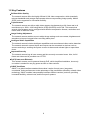
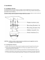
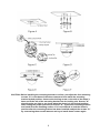
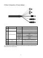
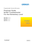
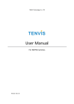
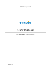
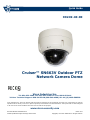
Quick Guide
XX249-40-00
Cruiser™ SN663V Outdoor PTZ
Network Camera Dome
Vicon Industries Inc.
Tel: 631-952-2288 Fax: 631-951-2288 Toll Free: 800-645-9116
24-Hour Technical Support: 800-34-VICON (800-348-4266) UK: 44/(0) 1489-566300
Vicon Industries Inc. does not warrant that the functions contained in this equipment will meet your requirements or that the
operation will be entirely error free or perform precisely as described in the documentation. This system has not been designed
to be used in life-critical situations and must not be used for this purpose.
www.vicon-security.com
Document Number: 8009-8249-40-00
Product specifications subject to change without notice.
Issued: 1113
Copyright © 2013 Vicon Industries Inc. All rights reserved.
2
1. Description
The SN663V network camera is an outdoor PTZ camera dome that includes a 1080p high
resolution camera lens combination that provides video transmission over a network. It is fully
featured for security surveillance and remote monitoring needs.
The network camera supports H.264 compression technology as well as M-JPEG compression. By
using its dedicated program, multiple users are able to have access to the network camera
simultaneously or a single user can monitor various network cameras at the same time. It also
enables users to play, store and retrieve a monitoring image by using a PC. All the settings and
real-time monitoring screens are provided through access to the web.
1.1 Components
The camera is designed to be a compact small size with a hard dome camera housing constructed
of aluminum, steel and plastic. The housing is designed to be mounted on a wall or a ceiling. The
housing meets the Protection Classification IP66 standards for dust and moisture resistance.
* Dome Camera
* Installation Guide/CD
* Template Sheet
* Mounting Bracket
* Safety Lanyard
* Accessory Kit
1) Mounting screws (PH6 x 35.0)
2) Plastic anchors
3) O-Rings
4) Torx wrench
* Accessory Connector
1) 3-pin terminal block
2) 6-pin terminal block
3
1
1
1
1
1
1
(4)
(4)
(4)
(1)
1
(1)
(1)
1.2 Key Features
• Brilliant Video Quality
The network camera offers the highly efficient H.264 video compression, which drastically
reduces bandwidth and storage requirements without compromising image quality. Motion
JPEG is also supported for increased flexibility.
• Triple Streams
The network camera can deliver triple video streams simultaneously at full frame rate in all
resolutions up to 1920 x 1080 using Motion JPEG (M-JPEG) and H.264. This means that
several video streams can be configured with different compression formats, resolutions and
frame rates for different needs.
• Image Setting Adjustment
The network camera enables users to adjust image settings such as contrast, brightness and
saturation to improve images before encoding takes place.
• Intelligent Video Capabilities
The network camera includes intelligent capabilities such as enhanced video motion detection.
The network camera’s external inputs and outputs can be connected to devices such as
sensors and relays, enabling the system to react to alarms and activate lights or open/close
doors.
• Improved Security
The network camera logs all user access and lists currently connected users. Also, its full
frame rate video can be provided over HTTPS.
• PoE (Power over Ethernet)
This network camera can be powered through PoE, which simplifies installation, since only
one cable is needed for carrying power as well as video controls.
• ONVIF Certificate
ONVIF is a global interface standard that makes it easier for end users, integrators,
consultants, and manufacturers to take advantage of the possibilities offered by network video
technology. ONVIF enables interoperability between different vendors’ products, providing
increased flexibility, reduced cost, and future-proof systems.
4
2. Installation
2.1 Installation Details
The dome camera is for use in surface or pendant mounting applications; the mounting location
and material must be capable of supporting loads of up to 4.4 lb (2.0 kg). (Pendent mounting must
use pendent mount accessory.)
The dome camera’s mounting bracket should be attached to a structural object, such as hard wood,
wall stud or ceiling rafter that supports the weight of the dome camera.
CAUTION: A silicone rubber sealant (customer provided) must be applied to seal the
housing to secure waterproofing.
2.1.1 Locking Dome Camera
A. Make screw holes on the ceiling using the supplied mounting Template Sheet (Figure A).
B. Secure the provided Mounting Bracket to the ceiling using supplied Anchors (4x) and
Mounting Screws (4x) (Figure B).
C. Attach the Safety Lanyard to the Safety Lanyard Hook of the Mounting Bracket (Figure C).
D. Align the locking tab on the bracket and the locking slot on the base of the dome (Figure D).
E. Turn the dome counterclockwise approximately 10 degree to the locked position (Figure E).
5
CAUTION: Before installing the mounting bracket to surface, pre-adjust the four mounting
screws "A" on the base of the dome camera to best match the mounting
bracket locked position. Unscrew the locking screw on the side of the dome's
base and fit the tab of the mounting bracket into the locking slot. Screws "A"
should not be too tight or too loose when the dome is in the locked position.
After setting the proper positions of screws "A," remove the mounting bracket
and install it to the mounting surface. If it is too difficult to lock the dome in
position after the mounting bracket has been installed readjust the screws "A"
by unscrewing them a small amount and try to install dome camera again.
6
2.2 Basic Configuration of Camera System
No.
Connector
1
3-pin terminal block
2
6-pin terminal block
Wire Color
Description
RED
24 VAC or 12 VDC+
WHITE
24 VAC or 12 VDC-
PINK
GND
GRAY
ALARM INPUT
BROWN
GND
YELLOW
ALARM OUTPUT
GREEN
RS485+
BLUE
RS485-
3
RJ-45
BLACK
Ethernet, RJ-45 port compatible with
10/100Mbps having PoE functionality.
4
STEREO
GRAY
AUDIO OUTPUT
5
STEREO
BLACK
AUDIO INPUT
The camera must be installed by qualified service personnel in accordance with all local and
federal electrical and building codes.
7
2.3 Connections
• Connecting the Network
Connect a standard RJ-45 cable to the network port of the camera. Generally a cross-over
cable is used for direct connection to a PC, while a direct cable is used for connection to a hub.
• Connecting Alarms
- AI (Alarm Input)
You can use external devices to signal the camera to react upon events. Mechanical or
electrical switches can be wired to the AI (Alarm Input) and G (Ground) connectors.
- G (Ground)
NOTE: All the connectors marked G or GND are common.
Connect the ground side of the alarm input and/or alarm output to the G (Ground) connector.
- AO (Alarm Output)
The camera can activate external devices such as buzzers or lights. Connect the device to
the AO (Alarm Output) and G (Ground) connectors.
• Connecting to the RS485
The camera can be controlled remotely by an external device or control system, such as a
control keyboard, using RS485 half-duplex serial communications signals.
• Connecting the Power
Connect power of 12 VDC or 24 VAC 1.5 A for the camera.
When using a 12 VDC adapter, connect the positive (+) pole to the ‘+’ position and
the negative (-) pole to the ‘-’ position.
Use satisfy clause 2.5 of IEC60950-1/UL60950-1 or Certified/Listed Class 2 power source only.
- Be careful not to reverse the polarity when connecting the power cable.
- A router featuring PoE (Power over Ethernet) can be used to supply power to the camera.
- If PoE and 12 VDC are both applied, this camera will be supplied with power from PoE.
- 24 VAC is recommended to use for the camera power for stable operation with heater kit.
If using PoE, the heater will not operate at all.
8
2.4 Network Connection & IP assignment
The network camera is designed for use on an Ethernet network and requires an IP address for
access. Most networks today have a DHCP server that automatically assigns IP addresses to
connected devices. By the factory default, your camera is set to obtain the IP address
automatically via DHCP server. If your network does not have a DHCP server the network camera
will use 192.168.1.100 as the default IP address.
If DHCP is enabled and the product cannot be accessed, run the “SmartManager” utility on the CD
to search and allocate an IP address, or reset the product to the factory default settings and then
perform the installation again.
1) Connect the network camera/device to the network and power up.
2) Start SmartManager utility (Start > All programs > SmartManager > SmartManager). The main
window will display, and after a short while any network devices connected to the network will
be displayed in the list.
3) Select the camera on the list and click right button of the mouse. The pop-up menu displays
as below.
4) Select Assign IP Address. The Assign IP window will display. Enter the required IP address.
NOTE: For more information, refer to the SmartManager User’s Manual.
9
3. Operation
The network camera can be used with Windows® operating system and browsers. The
recommended browsers are Internet Explorer®, Safari®, Firefox®, Opera™ and Google®
Chrome® with Windows.
NOTE: To view streaming video in Microsoft Internet Explorer, set your browser to allow ActiveX
controls.
3.1 Access from a browser
1) Start a browser (ex., Internet Explorer).
2) Enter the IP address or host name of the network camera in the Location/Address field of your
browser.
3) A starting page displays. Click Live View or Setup to enter web page.
4) The network camera’s Live View page appears in your browser.
10
3.2 Access from the internet
Once connected, the network camera is accessible on your local network (LAN). To access the
network camera from the Internet you must configure your broadband router to allow incoming data
traffic to the network camera. To do this, enable the NAT traversal feature, which will attempt to
automatically configure the router to allow access to the network camera. This is enabled from
Setup > System > Network > NAT. For more information, see “3.5.7 System > Network > NAT” in
the User's Manual.
3.3 Setting the admin password over a secure connection
To gain access to the product, the password for the default administrator user must be set. This is
done in the “Admin Password” dialog, which is displayed when the network camera is accessed for
the setup at the first time. Enter your admin name and password, set by the administrator.
NOTE: The default user name is ADMIN and the default password is 1234. If the password is lost,
the network camera must be reset to the factory default settings. Refer to “Resetting to the
factory default settings.”
To prevent network eavesdropping when setting the admin password, this can be done via an
encrypted HTTPS connection, which requires an HTTPS certificate (see NOTE below).
To set the password via a standard HTTP connection, enter it directly in the first dialog shown
below. To set the password via an encrypted HTTPS connection, see “3.5.7 System > Security >
HTTPS” in the User's Manual.
NOTE: HTTPS (Hypertext Transfer Protocol over SSL) is a protocol used to encrypt the traffic
between web browsers and servers. The HTTPS certificate controls the encrypted
exchange of information.
3.4 Live View Page
The Live View page offers several screen modes: 1920x1080, 1280x1024, 1280x720, 704x576,
704x480, 640x480 and 320x240. Users can select the most suitable of these modes. Adjust the
mode in accordance with your PC specifications and monitoring purposes.
11
1) Gene
eral controls
Live View Page
Setup Page
Help Page
The video drop-down lisst allows the
e selection of
o a custom
mized or prep
programmed
d video stre am on the Live
L
View page. Stream
m profiles are
a
configured under
u
Setup
p > Basic Co
onfiguration
n > Video & Image. Forr more
in
nformation, see “3.5.1 Basic Confiiguration > Video & Imaage” in the User’s
M
Manual.
solution dro
op-down listt allows the selection oof the most suitable
s
The res
video resolution
r
to
o be display
yed on Live View pagee.
The protoc
col drop-dow
wn list allow
ws the selec
ction of whicch combination of
protocols and
a method
ds to use de
epending on
n your view
wing requirem
ments, and
on the pro
operties of yyour network.
The presett drop-down
n list allows the selectio
on of the preeset numbe
er for the
PTZ came
era being ussed. This icon is inactiv
vated if the PTZ setting
gs are not
set.
2) Conttrol toolba
ar
The livve viewer to
oolbar is ava
ailable in th
he web brow
wser page only.
o
It displ ays the follo
owing
button
ns:
T
The Stop bu
utton stops the video s tream being
g played. Pressing the key again toggles
t
the
sttart and stop. The Starrt button co nnects to th
he network camera or sstarts playin
ng a video
sttream.
T
The Pause button paus
ses the vide
eo stream being
b
played
d.
T
The Snapsh
hot button takes a sna pshot of the
e current im
mage. The loocation whe
ere the
im
mage is savved can be specified.
s
T
The Digital Zoom butto
on activatess a zoom-in
n or zoom-out function ffor video im
mage on the
e
livve screen.
T
The Full Screen button
n causes the
e video ima
age to fill the
e entire screeen area. No
N other
w
windows will be visible. Press the 'E
Esc' button on the com
mputer keybboard to can
ncel full
sccreen view.
T
The Manual Trigger button activa
ates a pop-u
up window to
t manuallyy start or sto
op the
evvent.
T
The PTZ button activate
es a pop-up
p window fo
or Pan, Tilt and
a Zoom ccontrol.
U
Use this sca
ale to contro
ol the volum
me of the sp
peakers.
U
Use this sca
ale to contro
ol the volum
me of the microphone.
3) Vide
eo Streams
s
The ne
etwork cam
mera provide
es several im
mages and video strea
am formats.. Your requiirements
and th
he propertie
es of your ne
etwork will d
determine the type you
u use.
The Live View pa
age in the ne
etwork cam
mera provide
es access to
o H.264 andd Motion JP
PEG video
stream
ms, and to the list of av
vailable vide
eo streams. Other applications andd clients ca
an also
ectly, without going via
access these vide
eo streams//images dire
a the Live V
View page.
12
3.5 Network Camera Setup
This section describes how to configure the network camera, and is intended for product.
Administrators, who have unrestricted access to all the Setup tools; and Operators, who have
access to the settings for Basic Configuration, Live View, Video & Image, Audio, Event, Dome
Configuration, and System. The configuration categories are displayed along the left side of the
screen. Click on the category to be configured; the name will turn yellow and that configuration
screen will display.
You can configure the network camera by clicking Setup in the top right-hand corner of the Live
View page. Click on the question mark to access the online help that explains the setup tools.
When accessing the network camera for the first time, the “Admin Password” dialog appears. Enter
your admin name and password, set by the administrator.
NOTE: If the password is lost, the network camera must be reset to the factory default settings.
Refer to “Resetting to the Factory Default Settings”. The default user name is ADMIN and
the default password is 1234.
Resetting to the factory default settings
To reset the network camera to the original factory settings, go to the Setup > System >
Maintenance web page (described in “3.5.7 System > Maintenance” in the User’s Manual) or use
the Reset button on the network camera, as described below:
• Using the Reset button:
Follow the instructions below to reset the network camera to the factory default settings using the
Reset button.
1. Switch off the network camera by disconnecting the power adapter.
2. Press and hold the Reset button (SW1) on the board with your finger while reconnecting the
power.
3. Keep the Reset button (SW1) pressed for about 2 seconds.
4. Release the Reset button (SW1).
5. The network camera resets to factory defaults and restarts after completing the factory reset.
The unit now obtains the IP address automatically via DHCP.
CAUTION: When performing a Factory Reset, you will lose any settings that have been saved.
13
System Requirement for Web Browser
• Operating System: Microsoft Windows OS Series
• CPU: Intel® Core™ 2 Duo 2Ghz or higher, 1GB RAM or more, 10GB free disk or higher
• VGA: AGP, Video RAM 32MB or higher (1024x768, 24bpp or higher)
General Performance Considerations
When setting up your system, it is important to consider how various settings and situations will
affect performance. Some factors affect the amount of bandwidth (the bit rate) required, others can
affect the frame rate, and some affect both. If the load on the CPU reaches its maximum, this will
also affect the frame rate.
The following factors are among the most important to consider:
- High image resolutions and/or lower compression levels (or high bitrates) result in larger
images. Frame rate and Bandwidth affected.
- Accessing both Motion JPEG and H.264 video streams simultaneously. Frame rate and
bandwidth affected.
- Heavy network utilization due to poor infrastructure. Frame rate and Bandwidth affected.
- Heavy network utilization via wireless router due to poor infrastructure. Frame rate and
bandwidth affected.
- Viewing on poorly performing client PCs lowers perceived performance. Frame rate affected.
More Information
For more information, refer to the network camera User’s Manual, which is available on the CD
included in this package.
14
Vicon Industries Inc.
Internet Address: www.vicon-security.com
SN663V IP Camera Dome
50303612A