1
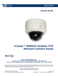
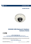
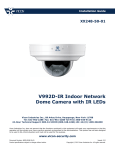
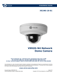
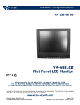
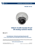
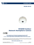
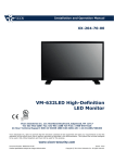
Quick Guide
XX249-41-00
Cruiser™ SN663V-A Outdoor PTZ
Network Camera Dome
Vicon Industries Inc.
Tel: 631-952-2288 Fax: 631-951-2288 Toll Free: 800-645-9116
24-Hour Technical Support: 800-34-VICON (800-348-4266) UK: 44/(0) 1489-566300
Vicon Industries Inc. does not warrant that the functions contained in this equipment will meet your requirements or that the
operation will be entirely error free or perform precisely as described in the documentation. This system has not been designed
to be used in life-critical situations and must not be used for this purpose.
www.vicon-security.com
Document Number: 8009-8249-41-00
Product specifications subject to change without notice.
Issued: 215
Copyright © 2015 Vicon Industries Inc. All rights reserved.
1
Introduction
The SN663V-A network camera is an outdoor PTZ camera dome that includes a 1080p high
resolution camera lens combination that provides video transmission over a network. It is
fully featured for security surveillance and remote monitoring needs.
The network camera supports H.264 compression technology as well as M-JPEG compression. By using its dedicated program, multiple users are able to have access to the network
camera simultaneously or a single user can monitor various network cameras at the same
time. It also enables users to play, store and retrieve a monitoring image by using a PC. All
the settings and realtime monitoring screens are provided through access to the web.
1.1
Components
The camera is designed with compact, small size, hard dome camera housing. The housing
is constructed of aluminum, steel and plastic. The housing is designed to be mounted on
a wall or a ceiling. The housing meets the Protection Classification IP66 standards for dust
and moisture resistance.
Dome Camera
·······································
Installation Guide/CD · · · · · · · · · · · · · · · · · · · · · · · · · · · · · · · · · · · · · · ·
Template Sheet
·······································
Mounting Bracket
·······································
Safety Lanyard
·······································
Accessory Kit
·······································
1) Mounting screws (PH6 x 35.0) · · · · · · · · · · · · · · · · · · (4)
2) Plastic anchors
· · · · · · · · · · · · · · · · · · (4)
3) O-Rings
· · · · · · · · · · · · · · · · · · (4)
4) Torx wrench
· · · · · · · · · · · · · · · · · · (1)
Accessory Connector · · · · · · · · · · · · · · · · · · · · · · · · · · · · · · · · · · · · · · ·
1) 3-pin terminal block
· · · · · · · · · · · · · · · · · · (1)
2) 6-pin terminal block
· · · · · · · · · · · · · · · · · · (1)
3
1
1
1
1
1
1
1
1.2
Key Features
• Brilliant video quality
The network camera offers the highly efficient H.264 video compression, which drastically reduces bandwidth and storage requirements without compromising image quality. Motion JPEG is also supported for increased flexibility.
• Dual or Triple Streams
The network camera can deliver dual or triple video streams simultaneously at full
frame rate in all resolutions up to Full-HD (1920 x 1080p) using Motion H.264 and
JPEG. This means that several video streams can be configured with different compression formats, resolutions and frame rates for different needs.
• Image setting adjustment
The network camera also enables users to adjust image settings such as contrast,
brightness and saturation to improve images before encoding takes place.
• Intelligent video capabilities
The network camera includes intelligent capabilities such as enhanced video motion
detection. The network cameras external inputs and outputs can be connected to devices such as sensors and relays, enabling the system to react to alarms and activate
lights or open/close doors.
• Improved Security
The network camera logs all user access, and lists currently connected users. Also, its
full frame rate video can be provided over HTTPS.
• PoE (Power over Ethernet)
This network camera can be powered through PoE, which simplifies installation since
only one cable is needed for carrying power, as well as video controls.
• ONVIF Certificate
This is a global interface standard that makes it easier for end users, integrators, consultants, and manufacturers to take advantage of the possibilities offered by network
video technology. ONVIF enables interoperability between different vendor products,
increased flexibility, reduced cost, and future-proof systems.
• Micro-SD Recording support
The network camera also supports a Micro-SD memory slot for local recording with
removable storage.
• Audio support
The network camera also supports two-way audio.
4
2
Installation
2.1
Installation
The dome camera is for use in surface or pendant mounting applications, and the mounting
member must be capable of supporting loads of up to 10 lb (4.5 kg). (Pendant mounting
must use pendant mount accessory.)
The dome cameras mounting bracket should be attached to a structural object, such as hard
wood, wall stud or ceiling rafter that supports the weight of the dome camera.
CAUTION: A silicone rubber sealant must be applied to seal the housing to secure waterproofing.
2.1.1
Locking Dome Camera
1. Make screw holes on the ceiling using the supplied mounting Template Sheet (Figure A).
2. Fix the Mounting Bracket to the ceiling using supplied Anchors (4x) and Mounting Screws (4x)
(Figure B).
3. Hook up the Safety Lanyard to the Safety Lanyard Hook of the Mounting Bracket (Figure C).
4. Align the locking tab on the bracket and the locking slot on the base of the dome (Figure D).
5. Turn the dome to the counterclockwise about 10 degree to the locked position (Figure E).
5
CAUTION: Before installing mounting bracket to surface pre-adjust the four mounting
screws ”A” on the base of the dome camera to best match the mounting bracket
locked position. Unscrew the locking screw on the side of the dome’s base and
fit the tab of the mounting bracket into the locking slot. Screws ”A” should not
be too tight or too loose when the dome is in the locked position. After setting
the proper positions of screws ”A” remove the mounting bracket and install it
to the proper surface. If it is too difficult to lock the dome in position after the
mounting bracket has been installed readjust the screws ”A” by unscrewing
them a small amount and try to install dome camera again.
6
2.2
Basic Configuration of Camera System
No.
Connector
Wire Color
RED
WHITE
PINK
GRAY
GREEN
BLUE
BROWN
YELLOW
1
3-pin terminal block
2
6-pin terminal block
3
RJ-45
BLACK
4
5
STEREO
STEREO
GRAY
BLACK
Description
24VAC or 12VDC+
24VAC or 12VDCALARM INPUT 1
ALARM INPUT 2
ALARM INPUT 3
ALARM INPUT 4
GND
ALARM OUTPUT
Ethernet, RJ-45 port compatible with
10/100Mbps having PoE functionality.
AUDIO OUTPUT
AUDIO INPUT
The camera must be installed by qualified service personnel in accordance with all local and
federal electrical and building codes.
7
2.3
Micro-SD Card Insertion
User can install and change Micro-SD card as shown in the following picture.
1. Open the Micro-SD card cover.
2. Install or change Micro-SD card.
3. Tightly close the Micro-SD card cover to ensure waterproofness.
8
2.4
Connections
• Connecting the Network
Connect a standard RJ-45 cable to the network port of the camera. Generally a crossover cable is used for directly connection to PC, while a direct cable is used for connection to a hub.
• Connecting Alarms
– A1,A2,A3,A4 (Alarm Input 1,2,3,4)
You can use external devices to signal the camera to react on events. Mechanical
or electrical switches can be wired to the A1,A2,A3,A4 (Alarm Input 1,2,3,4) and
G (Ground) connectors.
– G (Ground)
NOTE: All the connectors marked G or GND are common.
Connect the ground side of the alarm input and/or alarm output to the G (Ground)
connector.
– AO (Alarm Output)
The camera can activate external devices such as buzzers or lights. Connect the
device to the AO (Alarm Output) and G (Ground) connectors.
• Connecting the Power
Connect power of 12VDC or 24VAC for the camera.
When using a 12VDC adapter, connect the positive (+) pole to the ’ + ’ position and the
negative (-) pole to the ’ - ’ position.
Use satisfy clause 2.5 of IEC60950-1/UL60950-1 or Certified/Listed Class 2 power
source only.
– Be careful not to reverse the polarity when you connect the power cable.
– You can also use a router featuring PoE (Power over Ethernet) to supply power to
the camera.
– 24VAC is recommended to use for the camera power for stable operation with
heater kit. If using PoE, the heater will not operate at all.
9
2.4.1
Network Connection & IP assignment
The network camera is designed for use on an Ethernet network and requires an IP address for access. Most networks today have a DHCP server that automatically assigns IP
addresses to connected devices. By the factory default, your camera is set to obtain the IP
address automatically via DHCP server. If your network does not have a DHCP server the
network camera will use 192.168.1.100 as the default IP address.
If DHCP is enabled and the product cannot be accessed, run the SmartManager utility on
the CD to search and allocate an IP address, or reset the product to the factory default settings and then perform the installation again.
1) Connect the network camera/device to the network and power up.
2) Start SmartManager utility (Start > All programs > SmartManager > SmartManager).
The main window will display, and after a short while any network devices connected to the
network will be displayed in the list.
3) Select the camera on the list and click right button of the mouse. You can see the pop-up
menu as below.
4) Select Assign IP Address. The Assign IP window will display. Enter the required IP address.
NOTE: For more information, refer to the SmartManager Users Manual.
10
3
Operation
The network camera can be used with Windows operating system and browsers. The recommended browsers are Internet Explorer, Safari, Firefox, Opera and Google Chrome with
Windows.
NOTE: To view streaming video in Microsoft Internet Explorer, set your browser to allow
ActiveX controls.
3.1
Access from a browser
1. Start a browser (Internet Explorer).
2. Enter the IP address or host name of the network camera in the Location/Address field
of your browser.
3. You can see a starting page. Click Live View, Playback, or Setup to enter web page.
4. The network cameras Live View page appears in your browser.
11
3.2
Access from the internet
Once connected, the network camera is accessible on your local network (LAN). To access
the network camera from the Internet you must configure your broadband router to allow
incoming data traffic to the network camera. To do this, enable the NAT traversal feature,
which will attempt to automatically configure the router to allow access to the network camera. This is enabled from Setup > System > Network > NAT. For more information, please
see ”System > Network > NAT” of User’s Manual.
3.3
Setting the admin password over a secure connection
To gain access to the product, the password for the default administrator user must be set.
This is done in the Admin Password dialog, which is displayed when the network camera is
accessed for the setup at the first time. Enter your admin name and password, set by the
administrator.
NOTE: The default administrator user name is ADMIN and password is 1234 . If the password is lost, the network camera must be reset to the factory default settings. Please see
Resetting to the factory default settings.
To prevent network eavesdropping when setting the admin password, this can be done via
an encrypted HTTPS connection, which requires an HTTPS certificate (see NOTE below).
To set the password via a standard HTTP connection, enter it directly in the first dialog shown
below. To set the password via an encrypted HTTPS connection, please see ”System > Security > HTTPS” of User’s Manual.
NOTE: HTTPS (Hypertext Transfer Protocol over SSL) is a protocol used to encrypt the
traffic between web browsers and servers. The HTTPS certificate controls the encrypted
exchange of information.
12
3.4
Live View Page
The Live View page comes in several screen modes: 1920x1080, 1280x1024, 1280x720(960),
1024x768, 704x480(576), 640x480(360) and 320x240. Users are allowed to select the most
suitable one out of those modes. Adjust the mode in accordance with your PC specifications
and monitoring purposes.
1) General controls
Live View Page
Playback Page
Setup Page
Help Page
The video drop-down list allows you to select a customized or preprogrammed video stream on the Live View page. Stream profiles are configured under Setup > Basic Configuration > Video & Image. For more
information, please see ”Basic Configuration > Video & Image” of Users
Manual.
The resolution drop-down list allows you to select the most suitable one
out of video resolutions to be displayed on Live View page.
The protocol drop-down list allows you to select which combination of protocols and methods to use depending on your viewing requirements, and
on the properties of your network.
The preset drop-down list allows you to select the preset number for the
PTZ camera being used. This icon is inactivated if the PTZ settings are
not set.
13
2) Control toolbar
The live viewer toolbar is available in the web browser page only. It displays the following
buttons:
The Stop button stops the video stream being played. Pressing the key again toggles
the start and stop. The Start button connects to the network camera or starts playing
a video stream.
The Pause button pauses the video stream being played.
The Snapshot button takes a snapshot of the current image. The location where the
image is saved can be specified.
The Digital Zoom button activates a zoom-in or zoom-out function for video image on
the live screen.
The Full Screen button causes the video image to fill the entire screen area. No other
windows will be visible. Press the ’Esc’ button on the computer keyboard to cancel full
screen view.
The Manual Trigger button activates a pop-up window to manually start or stop the
event.
The PTZ button activates a pop-up window for Pan, Tilt and Zoom control.
The VCA button shows/hides VCA rule setting and detected objects.
The Face Detection button shows/hides detected faces.
The Speaker button activates/deactivates external speaker.
The Mic button activates/deactivates microphone input.
Use this scale to control the volume of the speakers and microphones.
NOTE: VCA and Face Detection works exclusively to each other.
3) Video Streams
The network camera provides several images and video stream formats. Your requirements and the properties of your network will determine the type you use.
The Live View page in the network camera provides access to H.264 and Motion JPEG
video streams, and to the list of available video streams. Other applications and clients
can also access these video streams/images directly, without going via the Live View
page.
14
3.5
Playback
The Playback window contains a list of recordings made to the memory card. It shows each
recording’s start time, length, the event type used to start the recording, calendar and time
slice bar indicates if the recording is existed or not.
The description of playback window follows.
(1) Video Screen
You can see the video screen when playing the video clip in the Micro SD memory.
(2) Playback Buttons
To view a recording data in the SD local storage, select it from the list and click the
Playback buttons.
Go to the first: go to the beginning of the video clip.
Fast backward play: fast play backward of the video clip.
Backward play: play backward of the video clip.
Step backward play: go back one frame of the video clip.
Pause: pause playback of the video clip.
Step forward play: go forward one frame of the video clip.
Forward Play: play forward the video clip.
Fast forward play: play fast forward of the video clip.
Go to the last: go to the end of the video clip.
Clip copy: copy the video clip.
Zoom In: zoom in the video clip.
Full Screen: display full screen of the video.
15
(3) Time Chart
Display an hour-based search screen for the chosen date. If there is recording data, a
blue section will be displayed on a 24-hour basis. If you select a particular hour in the
chart, a yellow square on the hour will be displayed.
(4) Speaker Control Bar
Use this scale to control the volume of the speakers.
(5) Search Calendar
Search results from the SD local storage in the network camera connected are displayed
monthly. If there is a recorded data for a particular date, a blue square on the date will be
displayed. If you select a particular date in the calendar, a yellow square on the date will
be displayed.
(6) Play Time
Displays time of the video playing.
(7) Event Search Window
Select a search option in the drop-down list and click GO button. You can also enter
the time period for searching. If you click Start Date or End Date zone, displays Search
Calendar.
(8) Event List Window
Event List displays the event(s) that were recorded in the SD local storage. Select a list
and click the play button. The video clip will be played.
16
3.6
Network Camera Setup
This section describes how to configure the network camera.
Administrator has unrestricted access to all the Setup tools, whereas Operators have access
to the settings of Basic Configuration, which are Live View, Video & Image, Audio, Event,
Dome Configuration, and System.
You can configure the network camera by clicking Setup either in the first connection page
or the top second-right button of the Live View page. Accessing the network camera from a
computer for the first time opens the Admin Password dialog box. Enter your administrator
or operator id and password to get into setup page.
NOTE: If the password is lost, the network camera must be reset to the factory default
settings. Please see ”Resetting to the Factory Default Setting”.
17
Resetting to the factory default settings
To reset the network camera to the original factory settings, go to the Setup > System >
Maintenance web page (described in ”System > Maintenance” of Users Manual) or use the
Reset button on the network camera, as described below:
• Using the Reset button:
Follow the instructions below to reset the network camera to the factory default settings using
the Reset button.
1. Switch off the network camera by disconnecting the power adapter.
2. Open the Micro-SD card cover.
3. Press and hold the Reset button (SW1) on the board with your finger while reconnecting the power. Refer to Figure 4 - Layout of DIP switch & Reset button.
4. Keep the Reset button (SW1) pressed for about 2 seconds.
5. Release the Reset button (SW1).
6. The network camera resets to factory defaults and restarts after completing the factory
reset. The unit now obtains the IP address automatically via DHCP.
7. Tightly close the Micro-SD card cover to ensure waterproofness.
CAUTION: When performing a Factory Reset, you will lose any settings that have been
saved.
18
System Requirement for Web Browser
• Operating System: Microsoft Windows OS Series
• CPU: Intel Core 2 Duo 2Ghz or higher, 1GB RAM or more, 10GB free disk or higher
• VGA: AGP, Video RAM 32MB or higher (1024x768, 24bpp or higher)
General Performance Considerations
When setting up your system, it is important to consider how various settings and situations
will affect performance. Some factors affect the amount of bandwidth (the bit rate) required,
others can affect the frame rate, and some affect both. If the load on the CPU reaches its
maximum, this will also affect the frame rate.
The following factors are among the most important to consider:
• High image resolutions and/or lower compression levels (or high bitrates) result in
larger images. Frame rate and Bandwidth affected.
• Accessing both Motion JPEG and H.264 video streams simultaneously. Frame rate
and bandwidth affected.
• Heavy network utilization due to poor infrastructure. Frame rate and Bandwidth affected.
• Heavy network utilization via wireless router due to poor infrastructure. Frame rate and
bandwidth affected.
• Viewing on poorly performing client PCs lowers perceived performance. Frame rate
affected.
More Information
For more information, please see the network camera Users Manual, which is available on
the CD included in this package.
19
Shipping Instructions
Use the following procedure when returning a unit to the factory:
1. Call or write Vicon for a Return Authorization (R.A.) at one of the locations listed below.
Record the name of the Vicon employee who issued the R.A.
Vicon Industries Inc.
135 Fell Court
Hauppauge, NY 11788
Phone: 631-952-2288; Toll-Free: 1-800-645-9116; Fax: 631-951-2288
For service or returns from countries in Europe, contact:
Vicon Industries (U.K.) Ltd
Brunel Way
Fareham, PO15 5TX
United Kingdom
Phone: +44 (0)1489/566300; Fax: +44 (0)1489/566322
2. Attach a sheet of paper to the unit with the following information:
a. Name and address of the company returning the unit
b. Name of the Vicon employee who issued the R.A.
c. R. A. number
d. Brief description of the installation
e. Complete description of the problem and circumstances under which it occurs
f. Units original date of purchase, if still under warranty
3. Pack the unit carefully. Use the original shipping carton or its equivalent for maximum
protection.
4. Mark the R.A. number on the outside of the carton on the shipping label.
20
Vicon Standard Equipment Warranty
Vicon Industries Inc. (the Company) warrants your equipment to be free from defects in material and workmanship under Normal Use from the date of original retail purchase for a period of three years, with the following
exceptions:
1. IQEYE Cameras: Two years if purchased before 1/1/2011.
2. IQEYE Cameras: Five years if purchased between 1/2/2011 12/31/2014.
3. Uninterruptible Power Supplies: Two years from date of original retail purchase.
4. VDR-700 Recorder Series: One year from date of original retail purchase.
5. V5616MUX: One year from date of original retail purchase.
6. Arecont Cameras: One year from date of original retail purchase.
7. FMC series fiber-optic media converters and associated accessories: Lifetime warranty.
8. For PTZ cameras, ”Normal Use” excludes prolonged use of lens and pan-and-tilt motors, gear heads,
and gears due to continuous use of ”autopan” or ”tour” modes of operation. Such continuous operation
is outside the scope of this warranty.
9. Any product sold as special or not listed in Vicons commercial price list: One year from date of original
retail purchase.
NOTE:
• If the product is to be used outdoors or in dusty, humid, or other hostile environments, it must be suitably
protected.
• Camera products must be protected, whether in use or not, from exposure to direct sunlight or halogen
light as the light may damage the camera image sensor. This applies to both indoor and outdoor use of
the cameras.
• For camera products supplied without a lens, extreme care should be used when mounting a lens on
these products. Damage to the product due to incorrectly mounted lenses will invalidate this limited
hardware warranty.
• Failure to comply with any of the aforementioned requirements will invalidate this Limited Hardware
Warranty.
Date of retail purchase is the date original end-user takes possession of the equipment, or, at the sole discretion of the Company, the date the equipment first becomes operational by the original end-user.
The sole remedy under this Warranty is that defective equipment be repaired or (at the Companys option)
replaced, at Company repair centers, provided the equipment has been authorized for return by the Company, and the return shipment is prepaid in accordance with policy. Repaired or replacement hardware will be
warranted for the remainder of the original Warranty Period or ninety (90) days, whichever is longer. When a
product or part is exchanged the replacement hardware becomes the property of the original purchaser and
all hardware or part thereof that is replaced shall become the property of Vicon.
The warranty does not apply (a) to faulty and improper installation, maintenance, service, repair and/or alteration in any way that is not contemplated in the documentation for the product or carried out with Vicon consent
in writing, operation adjustments covered in the operating manual for the product or normal maintenance, (b)
to cosmetic damages, (c) if the product is modified or tampered with, (d) if the product is damaged by acts of
God, misuse, abuse, negligence, accident, normal wear and tear and deterioration, improper environmental
conditions (including, but not limited to, electrical surges, water damage, chemical exposure, an/or heat/cold
exposure) or lack of responsible care, (e) if the product has had the model or serial number altered, defaced or
removed, (f) to consumables (such as storage media or batteries) (g) to products that have been purchased ”as
is” and Vicon the seller or the liquidator expressly disclaim their warranty obligation pertaining to the product,
(h) to any non-Vicon hardware product or any software (irrespective of packaged or sold with Vicon hardware
product) and Vicon products purchased from an unauthorized distributor/reseller, (i) to damage that occurs in
shipment or (j) to damages by any other causes not related to defective design, workmanship and/or materials.
The warranty for the products shall run from Vicon to End User customers only (including product purchased
through authorized partners and resellers). VIcon is not obligated under any circumstances to honor warranties
21
on product(s) purchases from internet auction sites including eBay, uBid or from any other unauthorized resellers. Except as explicitly provided herein, Vicon disclaims all other warranties, including the implied warranties of fitness for a particular purpose and merchantability.
Software supplied either separately or in hardware is furnished on an ”As Is” basis. Vicon does not
warrant that such software shall be error (bug) free. Software support via telephone, if provided at no
cost, may be discontinued at any time without notice at Vicons sole discretion. Vicon reserves the
right to make changes to its software in any of its products at any time and without notice.
The Warranty and remedies provided above are exclusive and in lieu of all other express or implied warranties including, but not limited to, the implied warranties of merchantability or fitness for a particular
purpose. Certain jurisdictions do not allow the exclusion of implied warranties. If laws under such
jurisdictions apply, then all express and implied warranties are limited to the warranty period identified
above. Unless provided herein, any statements or representations made by any other person or firm
are void. Except as provided in this written warranty and to the extent permitted by law, neither VIcon
nor any affiliated shall be liable for any loss, (including loss of data and information), inconvenience,
or damage, including, but not limited to, direct, special, incidental or consequential damages, resulting
from the use or inability to use the Vicon product, whether resulting from breach of warranty or any
other legal theory. Notwithstanding the foregoing, Vicon total liability for all claims under this warranty
shall not exceed the price paid for the product. These limitations on potential liabilities have been an
essential condition in setting the product.
No one is authorized to assume any liability on behalf of the Company, or impose any obligations on it in connection with the sale of any Goods, other than that which is specified above. In no event will the Company
be liable for indirect, special, incidental, consequential, or other damages, whether arising from interrupted
equipment operation, loss of data, replacement of equipment or software, costs or repairs undertaken by the
Purchaser, or other causes.
This warranty applies to all sales made by the Company or its dealers and shall be governed by the laws of
New York State without regard to its conflict of laws principles. This Warranty shall be enforceable against the
Company only in the courts located in the State of New York.
The form of this Warranty is effective February 1, 2015.
THE TERMS OF THIS WARRANTY APPLY ONLY TO SALES MADE WHILE THIS WARRANTY IS IN EFFECT. THIS WARRANTY SHALL BE OF NO EFFECT IF AT THE TIME OF SALE A DIFFERENT WARRANTY IS POSTED ON THE COMPANYS WEBSITE, WWW.VICON-SECURITY.COM. IN THAT EVENT,
THE TERMS OF THE POSTED WARRANTY SHALL APPLY EXCLUSIVELY.
VICON PART NUMBER: 8006-9010-03-11 Rev 0215
22