1
Model 5300
Three Phase
Power Analyzer
User ’s Manual
MAGTROL, INC.
Sales and TTechnical
echnical Assistance
70 Gardenville Parkway
Buffalo, New York 14224 USA
Tel: (716) 668-5555 or 1-800-828-7844
Fax: (716) 668-8705
ww w.
magtr
ol.c
om
w.m
agtro
l.co
Manufacturers of:
Motor Test Equipment
!
Hysteresis Brakes and Clutches
While every precaution has been exercised in the compilation of
this document, Magtrol, Inc. assumes no responsibility for errors
or omissions. Additionally, no liability is assumed for any damages
that may result from the use of the information contained within
this publication.
Trademark Acknowledgments
GPIB-PC is a trademark of National Instruments Corporation.
IBM is a registered trademark International Business Machines Corporation.
QuickBASIC is a registered trademark of Microsoft Corporation.
GE-MOV is a registered trademark of the General Electric Corporation.
FLUKE is a registered trademark of the John Fluke Mfg. Company.
Microsoft is a registered trademark of Microsoft Corporation.
Supercon is a registered trademark of the Superior Electric Company.
Rev. A 08/00
Table of Contents
SALES AND TECHNICAL ASSISTANCE .............................................................................................. ii
1 - INTRODUCTION ................................................................................................................................ 1
Abbreviations ...................................................................................................................................................... 1
Unpacking ........................................................................................................................................................... 1
Power .................................................................................................................................................................. 1
Fuse Replacement ............................................................................................................................................... 1
Safety .................................................................................................................................................................. 1
Connectors .......................................................................................................................................................... 1
Maximum Ratings............................................................................................................................................... 1
Installation ........................................................................................................................................................... 2
ORIENTATION .................................................................................................................................................................... 2
ELECTRICAL LOAD ............................................................................................................................................................ 2
IEEE-488 (GPIB) ........................................................................................................................................................... 2
Initial Checkout ................................................................................................................................................... 2
Transient Overloads ............................................................................................................................................ 2
Current Overload................................................................................................................................................. 2
2 - SPECIFICATIONS ............................................................................................................................. 3
Voltage ................................................................................................................................................................ 3
Current ................................................................................................................................................................ 3
Meter Impedance ................................................................................................................................................. 3
Resolution ........................................................................................................................................................... 3
Isolation ............................................................................................................................................................... 3
Display Auto Zero ............................................................................................................................................... 3
Analog Outputs ................................................................................................................................................... 3
Data Acquisition ................................................................................................................................................. 3
ANALOG ........................................................................................................................................................................... 3
DIGITAL ........................................................................................................................................................................... 4
Measurement Accuracy ....................................................................................................................................... 4
Accuracy Certification ........................................................................................................................................ 4
3 - CONNECTING THE 5300 .................................................................................................................. 5
Surge Protection .................................................................................................................................................. 5
Figure 1. Transient Voltage Suppression ..................................................................................................... 5
Connectors .......................................................................................................................................................... 5
AMPS ............................................................................................................................................................................... 5
VOLTS .............................................................................................................................................................................. 5
Single Phase AC or DC Connections ................................................................................................................. 6
Figure 2. Single Phase AC or DC Connections ........................................................................................... 6
3-Phase 3-Wire Delta Connections ..................................................................................................................... 7
Figure 3. 3-Phase 3-Wire Delta Connections .............................................................................................. 7
3-phase, 3-Wire WYE Connections .................................................................................................................... 7
iii
Figure 4. 3-phase, 3-Wire WYE Connections ............................................................................................... 7
3-Phase, 4-Wire WYE Connections ................................................................................................................... 8
Figure 5. 3-Phase, 4-Wire WYE Connections .............................................................................................. 8
3-Phase, Current and Potential Transformer Connections.................................................................................. 8
Figure 6. 3-Phase, Current and Potential Transformer Connections ......................................................... 8
4 - OPERATION ...................................................................................................................................... 9
General ................................................................................................................................................................ 9
Amperes Display ................................................................................................................................................. 9
Voltage Display .................................................................................................................................................. 9
Watts or Power Factor ........................................................................................................................................ 9
Mode Selections ................................................................................................................................................ 10
Figure 7. Mode Selections .......................................................................................................................... 10
MODE HOLD ................................................................................................................................................................... 10
MODE AVG ................................................................................................................................................................... 10
MODE POWER FACTOR (PF) ........................................................................................................................................... 10
MODE PH. V. ................................................................................................................................................................ 10
Display Selections ............................................................................................................................................. 11
Figure 8. Display Selections ....................................................................................................................... 11
DISPLAY Ø1, Ø2, Ø3 ..................................................................................................................................................... 11
DISPLAY SKW ............................................................................................................................................................... 11
Voltage Ranges ................................................................................................................................................. 11
Figure 9. Voltage Range Selections ............................................................................................................ 11
Amperes Range ................................................................................................................................................. 12
Figure 10. Current Range Selections ........................................................................................................... 12
Analog Output Option ...................................................................................................................................... 12
Figure 11. Analog Output Connections ........................................................................................................ 12
5 - CT/PT INSTALLATION .................................................................................................................... 13
Calibration ......................................................................................................................................................... 13
CT/PT Detection ............................................................................................................................................... 13
Figure 12. Current & Potential Transformer Selections ............................................................................. 13
CT/PT Ratio Range ...........................................................................................................................................
Digital Range ....................................................................................................................................................
GPIB-CT/PT Programming ..............................................................................................................................
Changing or Removing CT/PT Values .............................................................................................................
13
13
13
14
6 - GPIB COMMUNICATION ................................................................................................................. 15
GPIB (IEEE-488) .............................................................................................................................................. 15
Hardware Installation ........................................................................................................................................ 15
Software Installation ......................................................................................................................................... 15
Primary Address ................................................................................................................................................ 15
Figure 13. GPIB Address Selection .............................................................................................................. 15
7 - 5300 PA INSTRUCTION SET .......................................................................................................... 16
PC to 5300 PA .................................................................................................................................................. 16
5300 PA to PC .................................................................................................................................................. 16
iv
"SGL" INSTRUCTION ....................................................................................................................................................... 16
"FULL" INSTRUCTION ....................................................................................................................................................... 16
Data Rate ...........................................................................................................................................................
“Open” Instruction ............................................................................................................................................
Instruction .........................................................................................................................................................
Programming Example .....................................................................................................................................
17
17
17
17
8 - OPERATING PRINCIPLES .............................................................................................................. 19
Amperes Transducing ....................................................................................................................................... 19
Figure 14. 5300 Current Shunt Inputs .......................................................................................................... 19
Voltage Sensing ................................................................................................................................................ 19
Analog Processing ............................................................................................................................................ 19
Figure 15. 5300 Block Diagram ................................................................................................................... 20
Digital Processing ............................................................................................................................................. 20
Display “Help” .................................................................................................................................................. 20
Polyphase Line Balance .................................................................................................................................... 20
9 - CALIBRATION ................................................................................................................................. 21
General .............................................................................................................................................................. 21
Figure 16. Calibration Verification Test Setup ............................................................................................ 21
Test Setup.......................................................................................................................................................... 21
Calibration Verification .................................................................................................................................... 22
VOLTS CALIBRATION CHECK F1 ....................................................................................................................................... 22
AMPERES CALIBRATION CHECK ........................................................................................................................................ 23
WATTS CALIBRATION CHECK ........................................................................................................................................... 23
Minor Adjustment (If Needed) ......................................................................................................................... 23
Figure 17. Trimpot Adjustment Locations .................................................................................................... 24
VOLTS ZERO ................................................................................................................................................................... 24
AMPERES ZERO ............................................................................................................................................................... 24
VOLTS SCALE FACTOR ..................................................................................................................................................... 24
AMPERES SCALE FACTOR ................................................................................................................................................. 24
VOLTS BALANCE ............................................................................................................................................................. 25
CURRENT BALANCE ......................................................................................................................................................... 25
WATTS SCALE FACTOR .................................................................................................................................................... 25
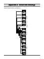
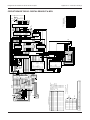
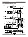
APPENDIX A: SCHEMATIC DRAWINGS ........................................................................................... 26
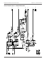
Circuit Board 78B128 - LED Display .............................................................................................................. 26
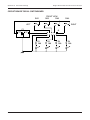
Circuit Board 78B145 - Digital Readout & MPU ............................................................................................ 27
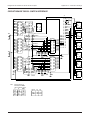
Circuit Board 78B146 - Analog Input board .................................................................................................... 28
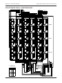
Circuit Board 78B147 - Converter Board ......................................................................................................... 29
Circuit Board 78B149 - Switchboard ............................................................................................................... 30
Circuit Board 78B153 - Switch Interface ......................................................................................................... 31
Circuit Board 78B154 - Counters Board .......................................................................................................... 32
Circuit Board 78B175 ....................................................................................................................................... 33
MAGTROL LIMITED WARRANTY ....................................................................................................... 34
v
This page intentionally left blank.
vi
1 - Introduction
ABBREVIATIONS
SAFETY
PA - Model 5300 Power Analyzer.
Securely ground the 5300 PA case by connecting a good
earth ground at the ground stud that is located on the
rear panel. Use a number 12 AWG wire, or larger.
GPIB - IEEE-488 Instrument Bus Standard.
LED - front panel indicator light.
A, V, W, PF and VA: Amperes, Volts, Watts, Power
Factor and Volt Amperes, respectively
CONNECTORS
The following plugs mate with 5300 PA connectors:
MPU - Microprocessor unit.
Superior Electric Supercon®
LSD, LSB - least significant digit or bit.
INPUT (plug, red, female) - PS100GR
CMRR - common mode rejection ratio.
OUTPUT (plug, red, male) - PP100GR
UNPACKING
The Model 5300 is packed in reusable, shock resistant
packing material that will protect the instrument during
normal handling. In the event of shipping damage,
immediately notify the carrier and Magtrol Customer
Service Dept. Save all shipping materials for reuse when
returning the instrument for calibration or servicing.
POWER
VOLTS LOW (plug, white, female) - PS25GWT
For your convenience, the above connectors are supplied
with your 5300 PA.
Use only the above connectors.
The 5300 PA is factory wired for either 120 or 240
Vrms, 50/60 Hz, power at 120 volt amps, max. The
line cord is a detachable NEMA standard 3 wire which
plugs into the rear access power entry and filter module
of the 5300 PA. The line cord must be detached from
the PA during servicing.
NOTE:
VOLTS HIGH (plug, black, female) - PS25GB
The standard 5300 is factory
wired for 120 Vrms power.
Wiring for 240 Vrms is available
on special order.
FUSE REPLACEMENT
Remove the line cord and carefully pry up and remove
the fuse holder. Use a 2 Amp slow blow fuse for 120
Vrms or a 1 Amp slow blow fuse for 240 Vrms power.
NOTE :
GPIB (IEEE-488) 24 Pin bus
standard cable is not included
with the 5300 PA and must be
ordered separately.
MAXIMUM RATINGS
LOAD current: 100 Amperes rms, continuous.
200 Amperes rms, 5 sec. max.
REMOTE VOLTAGE SENSE: Line to line is 600
Vrms. Also, do not exceed 600 Vrms differential
between the VOLTS INPUT and AMPS OUTPUT
terminals.
1
Chapter 1 - Introduction
Magtrol Model 5300 Three Phase Power Analyzer
INSTALLATION
TRANSIENT OVERLOADS
ORIENTATION
Connect an appropriate transient suppressor in parallel
with all inductive loads. Consult the suppressor vendor's
application literature for proper selection and sizing.
The 5300 PA must be mounted within ± 20 degrees
from horizontal. This ensures proper operation of the
mercury shunt bypass relays.
ELECTRICAL LOAD
Use wire rated for the maximum load current and voltage
expected.
Hint: Use wire gauge large enough to ensure good
connector set screw compression on the wire leads.
Soldering may be used instead of, or in addition to the
set screw.
Damage to the 5300 can result from
excessive voltage transients generated
by unsuppressed inductive loads. This
damage is not within the scope of the
normal instrument service and is not
covered by the Magtrol Warranty.
IEEE-488 (GPIB)
CURRENT OVERLOAD
Use only high quality shielded cable conforming to the
bus standards.
There are no fuses in the 5300 PA measuring circuits.
Therefore, excessive current passed through the AMPS
terminals will cause excessive internal heating and
possible unit damage.
INITIAL CHECKOUT
1. Make sure the circuit is completely de-energized
by removing all voltage sources.
2. Plug the 5300 PA into the 50/60 Hz power mains.
3. Switch the POWER rocker switch (red) to ON and
observe that the digit readouts flash on-off-on and
then indicate zero or a small number.
4. The VOLTS and AMPERES range switch indicator
lights will all illuminate. The voltage ranges will
sequence down from 600 through 150, and the
current ranges will sequence down from 100 through
5.
5. The 150 Volt and 5 Amp and AUTO indicators
remain illuminated. The MODE indicators will not
light during this power-on sequencing.
6. Your 5300 PA has passed the initial check.
2
This overload abuse is not covered by
the Magtrol Warranty.
Know your load conditions and double check all
connections. If an overload should occur, immediately
remove all power, and locate and correct the problem
before re-energizing your circuit. If a circuit breaker is
installed, it must be installed on the LOAD side of the
5300 (downstream). This will keep the low impedance
of the input line connected to the 5300 PA for surge
suppression. If the line side must also contain a breaker,
it should be delayed in operation to open after the load
side breaker has opened.
2 - Specifications
VOLTAGE
ISOLATION
Three DC and AC Ranges:
• 150, 300, and 600 Volts DC and Volts rms.
1500 Vrms break down from input circuit to chassis
(ground).
Remote Voltage Sensing:
• Differential input - 110 dB CMRR.
• Maximum of 30 Volts peak, volts low terminal
to amps output terminal.
CURRENT
Three DC and AC Ranges:
• 5, 25 and 100 Amps DC and Amps rms.
DISPLAY AUTO ZERO
When the A and V display indication is less than 0.5 %
of range, the displayed value is set to ZERO. Refer to
Section 5 - CT/PT Installation to disable the AUTO
ZERO function.
ANALOG OUTPUTS
This is an optional feature.
Current, DC or AC Ranges:
• 0.016 Ohm shunt resistance for 5 Amp range.
• 0.003 Ohm shunt resistance for 25 Amp ranges.
• 0.001 Ohm shunt resistance for 100 Amp range.
Analog AMPS, VOLTS and WATTS output signals
are DC proportional signals of 5.00 volts at full scale,
for each AMPS, VOLTS and WATTS range. Ripple is
less than 5 millivolts. The outputs are low impedance
operational amplifiers <1 Ohm and <4 milliamperes
current capacity. Each monitor signal and the common
are electrically isolated from the monitored circuits.
Isolation voltage is 750 Volts continuous and 2500 Volts
test breakdown. Leakage current is less than 0.3 micro
Amps at 240 Vrms, 60 Hz. Vrms
RESOLUTION
DATA ACQUISITION
Processing resolution is 16 binary bits.
ANALOG
METER IMPEDANCE
Voltage, DC or AC:
• 3 Megohm load on each voltage range.
Voltage Display Resolution:
• All ranges < 9.999 V is ± 0.001 Volt.
• Ranges > 10 V and < 99.9 V is ± 0.01 Volt.
• Ranges > 100 V is ± 0.1 Volt.
Current Display Resolution:
• All ranges < 9.999 A is ± 0.001 Amp.
• Ranges > 10 A and < 50 A is ± 0.01 Amp.
Power Display Resolution:
• Better than 0.015 % of the product of the active
Voltage and Amperes ranges.
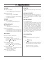
The conversion of true rms to DC is expressed as:
Vrms ≡
•
1T 2
∫ v ( t ) dt
T0
Rms to DC conversion averaging time constant:
Volts and Amps time constant TC ≅ 60 msec.
Watts time constant TC ≅ 120 msec.
Watts = V × I × cos θ (instantaneous)
GPIB: Amps, Volts and Watts
•
Same as display resolution.
3
Magtrol Model 5300 Three Phase Power Analyzer
Chapter 2 - Specifications
DIGITAL
•
•
ACCURACY CERTIFICATION
Processing:
Integration period = 0.10 second.
Display update time = 2 readings per second.
IEEE-488 (GPIB):
Synchronized = 0.1 sec. per reading
Non-synchronized is 0.04 to 0.07 sec per
reading.
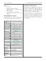
MEASUREMENT ACCURACY
Specified test conditions: Ambient temperature of 72°
± 10°F and power factor of 0.1 to 1.0, lead or lag.
VOLTAGE - DC
+ (0.1% of reading + 0.2% of range)
VOLTAGE - AC:
10 Hz to < 20 Hz + 1.0% of range
20 Hz to < 45 Hz + (0.2% of reading + 0.3% of range)
45 Hz to < 10 kHz + (0.1% of reading + 0.2% of range)
10 kHz to 20 kHz + (0.2% of reading + 0.5% of range)
CURRENT - DC
25 and 100 Amp Ranges
+ (0.1% of reading + 0.2% of range)
CURRENT - AC:
5 Amp Range
10 Hz to < 20 Hz + 1.0% of range
20 Hz to < 45 Hz + (0.2% of reading + 0.3% of range)
45 Hz to < 1 kHz + (0.1% of reading + 0.2% of range)
1 kHz to < 5 kHz + (0.2% of reading + 0.3% of range)
5 kHz to < 10 kHz + (1.0% of reading + 1.0% of range)
10 kHz to 20 kHz + (2.0% of reading + 2.0% of range)
25 Amp Range
10 Hz to < 5 kHz
same as 5 Amp range
5 kHz to 10 kHz + (2.0% of reading + 2.0% of range)
100 Amp Range
10 Hz to < 1 kHz + 0.5% of rng
1 kHz to 2 kHz + (2.0% of reading + 2.0% of range)
POWER - DC
+ (0.1% of reading + 0.2% of VA range)
POWER - AC
± [(0.1% of reading + 0.2% of (Amps
range × Volts range)]
POWER FACTOR
+ (VA error ± W error)
CREST FACTOR
Exceeds 3:1 (at 50% of range full scale)
TEMPERATURE
COEFFICIENT
+ 0.01% of range per deg. C maximum
DISPLAY
Digital display error ± 1 LSB.
4
All instruments are shipped with a Certificate of
Calibration from Magtrol Inc. Magtrol policies and
procedures comply with MIL-STD-45662A.
Measurement standards are traceable to the National
Institute of Standards and Technology (NIST).
Instrument calibration every six calendar months is
necessary to maintain full compliance with all
specifications. If a one year calibration cycle is used,
all accuracy specifications are reduced by 0.1%. After
one calendar year, the instrument is considered to be
out of calibration.
3 - Connecting the 5300
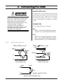
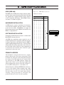
SURGE PROTECTION
Use Metal Oxide Varistors (MOV) or other equivalent
transient suppressors connected between lines at the load
(across the load). These suppressors are an absolute
necessity when inductive loads are used. In 3-phase
systems, each load must have a suppressor. See Figure
1 below.
Always install a properly rated circuit
breaker or fuse between the 5300 analyzer
and the load. Also, make sure that your
power source has its own fast-acting
disconnect and overload protection. See
"Current Overload" in Chapter 1 Introduction. Wire according to all
applicable wiring codes, making sure the
wire gauge and insulation ratings are
adequate for your application.
CONNECTORS
Use the supplied Supercon® connectors.
AMPS
INPUT - PLUG, RED, FEMALE-(PS100GR)
OUTPUT - PLUG, RED, MALE-(PP100GR)
VOLTS
HIGH - PLUG, BLACK, FEMALE-(PS25GB)
LOW - PLUG, WHITE, FEMALE-(PS25GWT)
SINGLE PHASE AC or DC CONNECTIONS
Figure 1.
Transient Voltage Suppression
V MOV > VLINE TO LINE
(LINE 1)
L1
V MOV >
V LINE TO LINE
(LINE 1)
L1
(LOAD)
MOV
1
3
MOV
(LOAD)
MOV
MOV
NEUTRAL
L2
L2
L3
MOV
MOV
L3
DELTA CONNECTED
THREE PHASE LOAD
(LINE)
LINE
HIGH
WYE CONNECTED
THREE PHASE LOAD
(LOAD)
MOV
LINE
LOW
V MOV > V LINE TO LINE
SINGLE PHASE TWO WIRE LOAD
5
Chapter 3 - Connecting the 5300
Magtrol Model 5300 Three Phase Power Analyzer
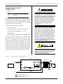
SINGLE PHASE AC OR DC
CONNECTIONS
See figure 2.
NOTE:
If a circuit breaker is used in the input line
to the 5300 PA, a circuit should be used
that prevents the breaker from opening until
after the load side breaker has opened.
Otherwise, potentially damaging inductive
transients can be applied to the 5300 PA.
Damage caused by these transients are
outside the scope of the MAGTROL
WARRANTY.
Connections are shown grouped
in cables.
This diagram shows the phase 1 (Ø1) voltage and current
inputs connected for measurement. However, any of
the 3-phase inputs can be used. The unused two inputs
are jumpered to insure zero inputs.
Power in watts is calculated as follows:
For voltage sense lines less than 25 feet in
length, a twisted pair of #20 gauge (or
larger) wire can be used. For lines longer
than 25 feet or lines grouped with other AC
conductors, shielded cable should be used.
Connect the shield at the 5300 PA GND
terminal. If the wires connecting the load to
the 5300 PA OUTPUT are short and the
resulting voltage drop is insignificant, the
voltage sense connections can be made at
the rear panel of the 5300 PA.
P = E × I × cos q
( where q is the phase angle between E and I)
On the 5300, select DISPLAY - Ø1 and
MODE -PH. V.
The 5300 displays VOLTS, AMPS and WATTS.
This circuit uses the 5300 PA remote voltage sense
feature by measuring the voltage at the load. This
increases measurement accuracy by eliminating line
voltage drop from the power measurement. For safety,
an overload circuit breaker (CB) removes all load
voltage during an over-current condition. The voltage
sense lines are connected at the line side of CB to help
prevent inductive transients from entering the PA as
the CB opens. Make sure that connections from CB to
the load are heavy conductors and short as possible.
Figure 2.
Connect the chassis ground terminal to
a good earth ground. Use at least #12
gauge insulated copper wire.
Single Phase AC or DC Connections
5300 PA
INPUT
(WHITE)
LOW
VLINE = VLOAD
R
R
AMPS
OUTPUT
Ø1
Ø1
Ø2
Ø2
Ø3
Ø3
VOLTS
LOW HIGH
R
W
B
R
W
B
VOLTAGE SENSE
2
1
ILINE = I LOAD
R
R
W
B
CB
LOAD
2
(BLACK)
HIGH
6
1
SURGE PROTECTION NOT SHOWN
2
INDICATES CABLING WITH 2 CONDUCTORS.
CABLE MUST BE FULL LOAD
EARTH
L
O
A
D
Magtrol Model 5300 Three Phase Power Analyzer
Chapter 3 - Connecting the 5300
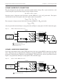
3-PHASE 3-WIRE DELTA CONNECTIONS
The power dissipated in each phase (PØ) is equal to the product of phase voltage ( Ephase), phase current (Iphase) and
cosine of the phase angle θ between the phase voltage and phase current:
PØ = Ephase × Iphase × cos θ
Each phase power is displayed on the 5300 PA by selecting DISPLAY - Ø1,Ø2 or Ø3 push switch. Total power
consumed by the load is the algebraic sum of the 3-phases power measurements:
PTOTAL = PØ1 + PØ2 + PØ3
The total power is displayed on the 5300 PA by selecting the DISPLAY - ΣKW push switch.
PTOTAL = ΣKW
Also, the general discussion for Figure 1 (surge protection) and Figure 2 (single phase AC & DC connection) apply.
Figure 3.
3-Phase 3-Wire Delta Connections
5300 PA
INPUT
AMPS
OUTPUT
LINE
L1
R
L2
R
L3
R
Ø1
Ø1
Ø2
Ø2
Ø3
Ø3
VOLTS
LOW HIGH
R
W
B
R
W
B
R
W
B
VOLTAGE SENSE
2
FOR BALANCED SYSTEM
I PHASE
LO
3
1
AD
=
LO
I LINE
AD
VLINE TO LINE = V PHASE
LOAD
CB
LOAD
EARTH
1
SURGE PROTECTION NOT SHOWN
2
INDICATES CABLING WITH 2 CONDUCTORS.
CABLE MUST BE FULL LOAD
2
3-PHASE, 3-WIRE WYE CONNECTIONS
Power conversion formulas for the 3-phase WYE connection are the same as for the DELTA connection as described
above. Each phase power is displayed on the 5300 PA by selecting the DISPLAY - Ø1,Ø2 or Ø3 push switch. The
total power is displayed on the 5300 PA by selecting DISPLAY - ΣKW push switch. Also, the general discussion for
Figure 1 (surge protection) and Figure 2 (single phase & DC connection) apply.
Figure 4.
3-phase, 3-Wire WYE Connections
5300 PA
INPUT
AMPS
OUTPUT
LINE
L1
R
L2
R
Ø1
Ø1
Ø2
Ø2
Ø3
Ø3
VOLTS
LOW HIGH
R
W
B
R
W
B
VOLTAGE SENSE
FOR BALANCED SYSTEM
VLINE TO LINE =
I LINE
=
3
V PHASE
L
O
A
D
I PHASE
L3
R
R
W
B
AD
LO
1
LO
AD
CB
EARTH
1
LOAD
SURGE PROTECTION NOT SHOWN
7
Chapter 3 - Connecting the 5300
Magtrol Model 5300 Three Phase Power Analyzer
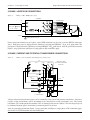
3-PHASE, 4-WIRE WYE CONNECTIONS
Figure 5.
3-Phase, 4-Wire WYE Connections
5300 PA
INPUT
AMPS
OUTPUT
LINE
L1
R
L2
R
Ø1
Ø1
Ø2
Ø2
Ø3
Ø3
VOLTS
LOW HIGH
R
W
B
R
W
B
VOLTAGE SENSE
FOR BALANCED SYSTEM
VLINE TO LINE =
I LINE
=
3
V PHASE
L
O
A
D
I PHASE
L3
R
R
W
B
D
A
LO
1
LO
AD
CB
LOAD
EARTH
NEUTRAL
1
SURGE PROTECTION NOT SHOWN
Power conversion formulas for the 3-phase 4-wire WYE connection are the same as for the DELTA connection,
above. Each phase power is displayed on the 5300 PA by selecting the DISPLAY - Ø1,Ø2 or Ø3 push switch. The
total power is displayed on the 5300 PA by selecting DISPLAY - ΣKW push switch. Also, the general discussion for
Figure 1 (surge protection) and Figure 2 (single phase & DC connection) apply.
3-PHASE, CURRENT AND POTENTIAL TRANSFORMER CONNECTIONS
Figure 6.
3-Phase, Current and Potential Transformer Connections
INPUT
AMPS
5300
PA
OUTPUT
VOLTS
LOW
HIGH
R
O1
O1
R
W
B
R
O2
O2
R
W
B
R
O3
O3
R
W
B
THREE PHASE CURRENT
AND POTENTIAL TRANSFORMER
CONNECTIONS
EARTH
LINE
PHASE
1
LOAD
CT
PHASE
2
CT
PHASE
CT
PT
PHASE
1
PT
PHASE
2
PHASE
PT
MAINTAIN POLARITY
Voltage and current measurement ranges can be extended by using current and potential transformers. Frequency
response of the measurements will be determined by the characteristics of the transformers used. The current
transformer (CT) and the potential transformer (PT) are shown located near the 5300 PA. The line voltage drop can
be eliminated from the power calculations by connecting the PT at the load.
Also, the general discussion from Figure 1 (surge protection) and Figure 2 (single phase & DC connection) apply.
See Section 5, CT/PT Installation for more information.
8
4 - Operation
Read Section 1 and make sure unit is connected properly
(see Section 3) before proceeding.
GENERAL
1. Using Sections 1 and 3 as a guide, connect the 5300.
Before connecting the power mains, double check
all connections (an Ohmmeter is helpful).
Verify that the overcurrent circuit breaker is open
and connect the power mains.
2. Observing the 5300 front panel indicators, turn the
5300 power switch ON and confirm proper
operation - see "Initial Checkout" in Section 1 Introduction.
3. Energize the power mains and apply power to the
load by closing circuit breaker CB. If improper
operation occurs, immediately disconnect power
mains. Locate and correct the problem.
The 5300 has:
• Four MODES - HOLD; AVG (averaging), PF
(Power factor) and PH. V. (phase voltage)
• Three AMPS ranges plus AUTO (auto ranging)
• Four DISPLAY selections -Ø1, Ø2, Ø3, (phases
1 through 3) and ΣKW (sum of kilowatts)
• Three VOLTS ranges plus AUTO.
All have adjacent red LEDs indicating the active mode
or measurement range.
AMPERES DISPLAY
The AMPS display is a four digit, unsigned floating
point display of true AC rms or DC current flowing
into the AMPS INPUT connector (red) on the rear panel.
For detailed information see Section 2, Specifications.
The 5300 defaults to AUTO (auto ranging) at DISPLAY
power turn on. AUTO up-ranging occurs if the rms
current exceeds the top of the range value plus about 5
%. AUTO down ranging occurs when the current is just
less than the full range value of the next lower range.
always silently monitoring the current and is ready to
up-range the instrument if the current increases above
105% of the range full scale. If the current falls below
the value of the selected range, that range will then
reactivate. The instrument will automatically up-range
from the measured current but will down-range only to
the selected range. The display will show "HELP" when
the maximum rating is exceeded.
VOLTAGE DISPLAY
The VOLTS display is a four digit, unsigned floating
point display of AC rms or DC voltage difference
between the rear panel HIGH (black) and LOW (white)
terminals. The voltage input is differential (neither
terminal tied to common) allowing connection at a
remotely located load. This remote connection removes
the voltage drop in the load connection wires from the
power measurement. The VOLTS - LOW terminal
(WHITE) must be connected to the AMPS -OUTPUT
line at the load - see Figure 1.
The AUTO and manual VOLTS range selection is
identical in operation to the AMPS, as described above.
WATTS OR POWER FACTOR
The WATTS display is five digit, unsigned floating
point display of power in WATTS or POWER FACTOR
(PF) as a decimal number. WATTS is the power ON
default MODE. Press the MODE - PF button to measure
POWER FACTOR.
Watts measurements are from about 100 milliwatts (auto
zero off) through 60 kilowatts, and Power Factors from
0.0001 through 0.9999. WATTS = V * I * cos * =
TRUE POWER The WATTS range is set by the AMPS
and VOLTS active ranges.
Power Factor is:
PF =
V × I × cos θ
V ×I
=
POWER
POWER
TRUE
APPARENT
Selection of any amps range push-button activates the
selected range by overriding the AUTO- range selection
- the AUTO LED goes off and selected AMPS LED
illuminates. However, the AUTO up-range function is
9
Magtrol Model 5300 Three Phase Power Analyzer
Chapter 4 - Operation
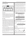
MODE SELECTIONS
Figure 7.
mode, the stored values will be returned as the new
averaging starting points. This function allows you to
exit the AVG mode, perform some other task, then
return and continue averaging where you left off. Also,
it can be used simply to retain and recall data.
Mode Selections
HOLD
AVG
PF
PH.V.
While in AVG mode and the PA power is turned off,
the last averaged values stored will be held in nonvolatile RAM and returned to the display when the PA
power is turned on and the AVG mode is reactivated.
The HOLD - AVG function permits truly integrated
power measurements where power is applied
intermittently, or where a combination of devices require
integrated measurements, with interruptions between
measurements.
MODE HOLD
The HOLD push-button may be depressed at any time.
When depressed, the displayed values are held and data
accumulation stops. If the AVG (averaging) function is
active when the HOLD button is depressed, the last
running average value of AMPS, VOLTS and WATTS
will be held. The HOLD and AVG functions can be
combined to provide added functions.
NOTE:
WATT-HOURS can be
determined by using the AVG
function and a timing clock.
Watt-hours = (watts avg × time
in hours).
NOTE:
Power Factor (PF) can not be
averaged.
MODE AVG
The AVG MODE is an integration or averaging function
for the display of VOLTS , AMPS and WATTS. The VOLTS,
AMPS and WATTS data are sampled at 10 readings per
second and a running average is computed by dividing the
summed values of each parameter by the total number of
summations. When averaging is turned off, the VOLTS,
AMPS and WATTS data, their summations, and the sample
count are stored in non-volatile RAM memory. The
averaging function is useful in stabilizing the display when
digits are changing because of slowly varying values.
Integration periods from seconds to minutes may be needed
to stabilize the displayed values.
The HOLD and AVG functions can work together.
When entering AVG with HOLD off, the averaging
registers are cleared and integration starts from a zero
value. With the HOLD function active first, pressing
AVG starts the integration point from the last RAM
stored values of AMPS, VOLTS or WATTS. The
HOLD automatically resets off.
When AVG is turned off, non-averaged values are
displayed and the averaged values are then stored in
non-volatile RAM memory. Upon re-entering the AVG
10
MODE POWER FACTOR (PF)
Pressing the PF (power factor) push switch displays the
power factor on the WATTS display. Power factor is
computed by:
PF =
P 1+ P 2 + P
φ
V
φ 1
I 1+V
φ
φ
φ 2
I
φ 2
φ 3
+V I
φ 3
φ 3
AVG mode is not active while in PF mode
MODE PH. V.
Pressing the PH. V push switch modifies the phase
VOLTS measurement to indicate line to line voltage on
the display by applying:
E LINE = E PHASE ×
3
This relation is valid for a balanced system. For an
unbalanced system, there can be a difference between
the displayed voltage and the true line to line value.
Magtrol Model 5300 Three Phase Power Analyzer
Chapter 4 - Operation
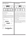
DISPLAY SELECTIONS
VOLTAGE RANGES
Figure 8.
Figure 9.
Display Selections
Ø1
Ø2
Ø3
Σ KW
150
DISPLAY Ø1, Ø2, Ø3
Individually selects Phase 1, Phase 2 or Phase 3
WATTS for display.
If all three push-buttons are simultaneously pressed, the
four LEDs illuminate, indicating that the AMPS display
reads the SUM of the three phase currents, the VOLTS
reads the AVERAGE of the three phase voltages and
the WATTS reads SUM of the three phase powers, as
follows:
AMPERES = Iφ 1 + Iφ 2 + Iφ 3
VOLTS =
V φ1 + V φ 2 + V φ 3
3
KILOWATTS =
W φ1 + W φ 2 + W φ 3
1000
Voltage Range Selections
(SUM)
(AVERAGE)
300
600
AUTO
150, 300 and 600 volts rms plus AUTO range. At power
turn on, the 150 volt range and AUTO (auto-ranging)
are active, by default. Up ranging occurs when the
measured voltage on any phase exceeds that range
maximum voltage by 5% (>105%). This feature is active
in either AUTO (LED on) or manual (LED off).
Automatic down ranging occurs only in AUTO when
the measured voltage falls to about 1/4% below that
range maximum value.
If MODE PH. V. is off, up ranging occurs at 105% of
the range times 3 .
The PA up-ranging feature protects the instrument from
overload and ensures accurate measurements.
Exceeding the PA maximum voltage of 600 volts causes
the instrument to display "HELP." This means that
you must reduce your input voltage.
(SUM)
DISPLAY Σ KW
The WATTS display indicated the total 3-phase power
in kilowatts.
KW =
W
φ1
+ W φ2 +W
φ3
(SUM)
1000
11
Magtrol Model 5300 Three Phase Power Analyzer
Chapter 4 - Operation
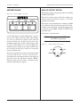
AMPERES RANGE
ANALOG OUTPUT OPTION
Figure 10.
This option provides analog output signals for AMPS,
VOLTS and WATTS.
5
Current Range Selections
25
100
AUTO
These three analog outputs with their common are
isolated from the measured circuits at 750 Volts
continuous breakdown.
The outputs are provided through a standard 5 pin DIN
style connector located on the rear panel of the 5300 see figure 11 for connections. The analog output voltage
is 5.00 volts at each AMPS, VOLTS or WATTS range
maximum value.
See Section 2 - Specifications.
5, 25 and 100 Amperes rms plus AUTO range: At power
turn on, the 5 Amps range and AUTO (auto ranging)
are active, by default. Up ranging occurs when the
measured current on any phase exceeds that range
maximum current by 5% (>105%). This feature is active
in either AUTO (LED on) or manual (LED off).
Automatic down ranging occurs only in AUTO when
the measured current falls to about ¼% below that
range's maximum value.
The PA up-ranging feature protects the instrument from
overload and ensures accurate measurements.
Exceeding the PA maximum current of 100 Amps on
any phase causes the instrument to display "HELP."
This means that you must reduce your input current
until the normal display reappears.
12
NOTE:
Figure 11.
Analog output of POWER
FACTOR is not provided
Analog Output Connections
N/C
5
WATTS
4
3
1
COM
2
AMPS
VOLTS
5 - CT/PT Installation
External current and potential transformers can be used
to extend the measuring ranges of the PA. See Section
4, Figure 6 for a connection diagram.
CALIBRATION
The 5300 PA compensates all display values for
transformer ratios from 0.01 to 255.
DIGITAL RANGE
The 5300 has special provisions allowing entry of
transformer ratios into the non-volatile RAM via the
GPIB (IEEE-488) rear panel input. The PA display
then includes the transformer ratios and reads actual
current, voltage and power directly.
CT/PT DETECTION
At power turn on initialization, the MPU interrogates
that portion of memory where the CT and PT
compensation values reside. If a value is found, the MPU
looks to see if the rear panel CT/PT slide switch (see
Figure 12) is set to the "IN" position (to include the
transformer ratios). If it is, normal calibration factors
are revised by applying the transformer factors. The
displays indicate actual load values.
Figure 12.
CT/PT RATIO RANGE
Current & Potential Transformer Selections
The digital display holds four digits for AMPS and
VOLTS, and five digits for WATTS or KW. When a
value exceeds these limits, the decimal point is turned
off. This is a warning that the compensated value is
above the display capability and is in error. If this should
occur during GPIB use, an exclamation mark is
substituted immediately to the right of the least
significant digit (i.e. !=ASCII033) to signal that there
is an unknown magnitude.
GPIB-CT/PT PROGRAMMING
The 5300 PA accepts either upper or lower case
characters, and whole numbers in any numerical format.
For CT installation: CTnnncl
For PT installation: PTnnncl
Where: nnn=0.01 to 255.
("cl" denotes a carriage return/line feed termination
character.)
For example:
A CT with 250:1 ratio is: CT250.cl
A PT with 10:1 ratio is: PT10.0ct
IN
OUT
GND
EXT
CT/PT
The PA will ignore any value outside of the range of
0.01 to 255. If an out of range entry is attempted, the
display will warn by showing "HELP." Correct and reenter your factor.
Since the above interrogation and scale factor setup
occurs only at power turn on, the scale factors are active
until power is turned off, the CP/PT switch turned to
"OUT" and power turned "ON." The CP/PT factors
are now removed and the standard factory calibration
factors become active.
13
Chapter 5 - CT/PT Installation
CHANGING OR REMOVING CT/PT
VALUES
To modify a value, simply overwrite the existing
value(s).
To remove a CT or PT value, output a CT(cl) or PT(cl),
only.
To remove both, and save the data, switch the rear panel
slide switch to "OUT," and toggle the power OFF then
ON.
If you remove both the CT and PT value correction
factors by GPIB instructions, the PA will automatically
reset, eliminating the need to cycle power OFF/ON.
NOTE:
14
When removing transformer
conversion factors and measuring
without CT(s) or PT(s), set the
rear panel CT/PT switch to the
"OUT" position.
Magtrol Model 5300 Three Phase Power Analyzer
6 - GPIB Communication
GPIB (IEEE-488)
Figure 13.
The IEEE-488 or GPIB (General Purpose Interface Bus)
provides direct connection and control of the 5300 from
any appropriately equipped computer for the purpose
of data acquisition and display. MAGTROL factory
assistance is available if required.
(Address 14 shown)
HARDWARE INSTALLATION
A GPIB interface requires installation of an interface
card in the host computer and driver software resident
on the PC's hard disk. MAGTROL can supply the
National Instruments Corp. GPIB-PC2A® interface for
IBM® or compatible PCs.
SOFTWARE INSTALLATION
Formatting and initialization assistance is available from
MAGTROL Customer Service.
All GPIB data acquisition systems require the use of
termination characters to signal the conclusion of a data
exchange. The 5300 uses the Hewlett Packard - HPIB™
standard ASCII termination characters "Carriage Return
(CR) and Line Feed (LF)," in that order. On a read cycle,
the 5300 looks for the CR-LF to signal completion of
an instruction and transmits these characters upon
conclusion of a data write cycle.
GPIB Address Selection
SWITCH SEGMENT
ADDRESS
1
LSB
2
3
4
5
MSB
0
1
0
1
0
1
0
1
0
1
0
1
0
1
0
1
0
1
0
1
0
1
0
1
0
1
0
1
0
1
0
1
0
0
1
1
0
0
1
1
0
0
1
1
0
0
1
1
0
0
1
1
0
0
1
1
0
0
1
1
0
0
1
1
0
0
0
0
1
1
1
1
0
0
0
0
1
1
1
1
0
0
0
0
1
1
1
1
0
0
0
0
1
1
1
1
0
0
0
0
0
0
0
0
1
1
1
1
1
1
1
1
0
0
0
0
0
0
0
0
1
1
1
1
1
1
1
1
0
0
0
0
0
0
0
0
0
0
0
0
0
0
0
0
1
1
1
1
1
1
1
1
1
1
1
1
1
1
1
1
0
1
2
3
4
5
6
7
8
9
10
11
12
13
14
15
16
17
18
19
20
21
22
23
24
25
26
27
28
29
30
31
1 2 4 8 16
1 2 3 4 5 6 7 8
1
0
Not Used
PRIMARY ADDRESS
All instruments serviced on the bus have a separate
primary address code. The factory setting for the 5300
is fourteen (14). This code can be changed by changing
the settings of the DIP switch that are located on the
rear panel next to the GPIB connector. Change this
address only if there is a bus addressing conflict with
other instrumentation. Refer to the table in Figure 13
to set the DIP switch pattern - set to address 14.
Some PC interfaces (National GPIB-PC2A) will access
0 to 15 (4 bit) primary address numbers only. Other
interfaces may access up to 31 (5 bit code). The 5300
PA code range uses the 5 bit code format. Before
selecting a value greater than 15, check that your
particular interface has the 5 bit code capability.
15
7 - 5300 P
A Instruction Set
PA
PC TO 5300 PA
In addition to the standard instructions listed in the table
on the left, there are special instructions for reading and
writing directly to the PA memory elements.
A5, A25, A100
AMPERES RANGE selection.
V150, V300, V600
VOLTAGE RANGE selection.
AA
AMPS AUTO range ON.
VA
VOLTS AUTO range ON.
FULL
SGL
SYNC
OPEN
Sets data FORMAT to AMPS,
VOLTS, WATTS for 3 phases.
See 5300 PA TO PC.
Sets data output format = to
front panel display. See 5300
PA to PC.
GPIB data output rate is
synchronized to 0.10 sec. bus
output rate. See DATA RATE.
Data OUTPUT is transmitted
upon request. See OPEN
INSTRUCTION.
A specific program running in the host computer is
necessary. If you have a special situation where you
want direct memory access to alter 5300 PA functions
or change calibration, please contact Magtrol for
software assistance.
5300 PA TO PC
There are two choices for VOLTS, AMPS and WATTS
data format. Before you execute a read statement, it is
necessary to instruct the PA as to which data format
you wish to receive. This selection is retained by the
PA and becomes the default mode used for subsequent
data transmissions.
"SGL" INSTRUCTION
SP1, SP2, SP3
Selects PHASE 1, 2, or 3.
SPA
Selects ALL PHASES (same
as pressing Ø1, Ø2 and Ø3
simultaneously).
LV
Select to read LINE VOLTAGE.
PV
Select to read each PHASE
VOLTAGE.
KW
select to read KILOWATTS
W
Select to read PHASE WATTS.
P
Select to read POWER
FACTOR.
I, IC
Averaging ON, Averaging OFF.
H, HC
HOLD ON, HOLD OFF.
L, LC
LOCKOUT, and LOCKOUT
CLEAR of all front panel push
switches.
"FULL" INSTRUCTION
AZ
Cancel of AUTO ZERO
function.
Data for all 3-phases is supplied. The string is 68
contiguous ASCII characters:
CT, PT
CANCEL, or ENTER data for
current or potential transformer
calibration.
A=xx.xxV=xxx.xW=xxxx.xA=yy.yyV=yyy.yW=yyyy.yA=zz.zzV=zzz.zW=zzzz.z••
RES
16
Soft RESET of PA (same as
power on).
Sets the data format to a string length of 24 ASCII
characters, including carriage return and line feed
combination (••).
A=nn.nnV=nnn.nW=nnnn.n••
n (as shown) is any integer number 0 through 9
V (as shown) is volts
W (as shown) is watts
P is power factor
K is kilowatts
•• is carriage return and line feed combination
NOTE:
Use leading zeros to maintain a
fixed string length.
x is an integer number 0 through 9 for phase 1.
y is an integer number 0 through 9 for phase 2.
z is an integer number 0 through 9 for phase 3.
Magtrol Model 5300 Three Phase Power Analyzer
Chapter 7 - Instruction Set
This string transmits volts, watts and amps. To get line
voltage, power factor (PF) or kilowatts (KW), the host
computer must make the following calculations:
PF
=
E
E LINE
∅ 1
W
∅ 1
I∅
1
(n )
+W
+ E
∅ 2
∅ 2
I∅
+W ∅ 3
2 + E ∅ 3I∅
= E PHASE
( n)
3
3
(Where “n” is the phase number)
KW =
W
φ1
+ W φ2 +W
φ3
1000
DATA RATE
The OPEN and SYNC commands affect bus timing.
Selection is dependent upon what other instruments are
on the bus, their acquisition rate, and how you wish to
process the data.
“OPEN” INSTRUCTION
If your data acquisition is random, or you don't want to
wait for the full 0.1 second data sampling rate, you can
use the OPEN instruction. Data output is nearly
immediate, depending upon the MPU status at the time
of request. If multiple data
Output any instruction (except "RES") to each
of the instruments without including the
combination carriage return/line feed (oo)
terminating instruction. Now, both instruments
are "hung up" at fixed program locations
waiting for the carriage return/line feed
instruction. Synchronization is accomplished by
restarting both programs by outputting only the
carriage return/line feed instruction (oo) in
successive statements to both instruments.
At restarting, the instrument will be synchronized, but
will slowly drift apart and require re-synchronization.
If you are acquiring data in batches, execute the above
synchronization routine just prior to each data input
routine.
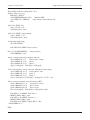
PROGRAMMING EXAMPLE
The following program sets the 5300 PA in the "SYNC"
mode with "FULL" data format. The CRT monitor
displays:
Amperes - summed for total 3-phase line.
Voltage - average 3-phase line.
Power - 3-phase kilowatts.
This example (on the following page) assumes that the
National GPI-PC interface hardware and Microsoft
Quick Basic are used.
requests are made within the MPU's 0.1 second sample
rate, you will receive multiple transmissions of the same
data. If your program is accumulating data in an array,
you will want to include a routine to ignore the second
of any two identical received data words.
INSTRUCTION
The host PC will be held by the 5300 PA until the
sampling period is over. In this mode, data will always
be the result of the most recent sampling period.
However, if you are using a Magtrol controller like the
Model 4629B or 5240, the two instruments should be
synchronized to avoid a timing conflict. This
synchronization is done as follows:
17
Chapter 7- Instruction Set
Magtrol Model 5300 Three Phase Power Analyzer
'Read 5300 PA full data - Magtrol Inc., 91 rt
'Primary address set to 14
Bdname$ = "DEV14"
CALL IBFIND(Bdname$, bd%)
'initialize GPIB
cl$ = CHR$(13) + CHR$(10)
'assign carriage return and line feed.
CLS
'Set PA for "FULL" data
wrt$ = "FULL" + cl$
CALL ibwrt(bd%, wrt$)
'Set PA for "SYNC" transfer timing.
wrt$ = "SYNC" + cl$
CALL ibdwrt(bd%, wrt$)
'Assign input word length.
rd$ = SPACE$(68)
LOCATE 20,50: PRINT "Any key ends..."
DO: s$ = UCASE$(INKEY$)
CALL IBRD(bd%, rd$)
'Loop starts here.
'Amps - convert from string to numeric and sum.
ap1$ = MID$(rd$, 3, 5)
'Extract Phase 1 amps.
ap2$ = MID$(rd$, 25, 5)
'phase 2.
ap3$ = MID$(rd$, 47, 5)
'phase 3.
amps = VAL(ap1$) + VAL(ap2$) + VAL(ap3$)
'Volts, conv' numeric, average, and conv' from phase to line voltage.
vp1$ = MID$(rd$, 10, 5)
'extract phase 1 volts.
vp2$ = MID$(rd$, 32, 5)
'phase 2.
vp2$ = MID$(rd$, 54, 5)
'phase 3.
volts = (VAL(vp1$) + VAL(vp2$) + VAL(vp3$) * .57735 ' = |3/3
'Power, convert to numeric, sum and convert to KW.
wp1$ = MID$(rd$, 17, 6)
'extract phase 1 watts.
wp2$ = MID$(rd$, 39, 6)
'phase 2 watts.
wp3$ = MID$(rd$, 61, 6)
'phase 3 watts.
Kw = (VAL(wp1$) + VAL(wp2$) + VAL(wp3$)) / 1000
LOCATE 12, 10: PRINT "Line Volts = ";
PRINT USING "###.#"; volts
LOCATE 13, 10: PRINT "Amperes = ";
PRINT USING "###.#"; amps
LOCATE 14,10: PRINT "3-phase KW = "; Kw
LOOP WHILE s$ = ""
END
18
8 - Operating P
rinciples
Principles
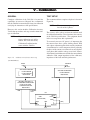
The Magtrol 5300 PA uses the three wattmeter method
to measure true RMS power. Voltage and current are
sensed and amplified in an isolated analog front end,
analog to digital converted with 16 bit precision,
processed through an 8 bit microprocessor (MPU) and
output in BCD form for display on the front panel
meters. The PA provides a digital display for each
selected phase of rms volts, amps, and watts; average
rms volts, amps and watts; and total load power factor
(PF).
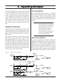
VOLTAGE SENSING
Each VOLTS input terminal connects a 1.5 Megohm
resistive voltage divider to provide scaled phase voltage
for measurements. The three 1.5 Megohm resistors form
a classic "Y Box" neutral. The resulting phase voltage
signals are amplified and scaled for processing. See
Figure 14.
NOTE:
AMPERES TRANSDUCING
Current measuring is accomplished using a three section
calibrated manganin resistance shunt per phase. The 5,
25 and 100 amp sections are 0.016 Ohm (80 mV), 0.003
Ohm (75 mV) and 0.001 Ohm (100 mV), respectively.
See Figure 14.
The current flow through each shunt is determined by
measuring the voltage drop across the shunt and the
MPU, applying Ohm's Law. Current ranges are set by
the MPU and energize the appropriate shunt bypass
relays CR1 and CR2. The 5 amp range energizes (opens
N/C contacts) of both CR1 and CR2; the 25 Amp. range
energizes CR1, and both relays remain de-energized for
the 100 Amp range. The CRs are very low resistance,
high current mercury wetted relay contacts that bypass
unused sections of the metering shunts.
Figure 14.
Connecting the Voltage Sense
leads incorrectly (e.g. connecting
the voltage sense from phase 1 to
phase 2 current lines) will cause
the Watts display to show an
incorrect value. If you are
experiencing poor readings, shut
down the system and carefully
review your connections.
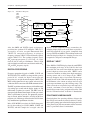
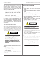
ANALOG PROCESSING
Input signals proportional to AMPS and VOLTS are
amplified and calibrated for each range by amplifiers
78B146-U7, U8, U9 and U10. These scaled signals pass
through true rms to DC converters 78B147-U1 & U4,
voltage to frequency converters 78B147-U2 & U5 and
optical isolators 78B147-U3 & U6. The resulting
frequency signals represent true rms current and voltage
(AF0 and VF0,) scaled to 0.0707 volts per 1.0 kilohertz.
5300 Current Shunt Inputs
OUTPUT
01
INPUT
01
S (LOAD)
CR2
CR1
E PH1
VOLTS
(HIGH)
E PH2
VOLTS
(HIGH)
E PH3
VOLTS
(HIGH)
VOLTS 01
(LOW)
5A
25A
100A
OUTPUT
02
S (LOAD)
02
CR2
CR1
VOLTS 02
03 (LOW)
S (LOAD)
03
CR2
CR1
VOLTS 03
(LOW)
19
Chapter 8 - Operating Principles
Figure 15.
Magtrol Model 5300 Three Phase Power Analyzer
5300 Block Diagram
AMPS
INPUT
(FROM
SHUNTS)
78B146-U7
5A
ISOLATED CIRCUIT
I5AMP
RANGE
78B147-U1
78B146-U8
25A
Vrms=
I25 AMP
1
T 0
t
78B147-U2
V/F CONV.
V 2 (t) dt
OUTPUTS
TO
MPU
78B147-U3
OPTO
ISO
VOLT
.0707
Khz
AFo
78B146-U9
78B147-U7
100A
I100 AMP
X
VOLTS INPUT
(FROM
VOLTAGE
DIVIDER)
V
78B146-U10
V AMP
78B147-U9
Y
Vo= XYCosQ
10
U8
78B147-U4
Vrms=
1
T 0
t
V 2 (t) dt
Also, the AMPS and VOLTS signals are input to a
precision four quadrant X-Y multiplier 78B147-U7,
averaged by an active two pole Butterworth filter
78B147-U8, converted to frequency in voltage to
frequency converter 78B147-U10 and isolated by optical
coupler 78B147-U11. The resulting frequency signal,
WF0 represents true power (V × I × Cos θ ), at a scale
factor of. 0.0707 volts per 1.0 kilohertz. There is 2500
volts isolation between the measured circuit and the AF0,
VF0 and WF0 frequency signals.
DIGITAL PROCESSING
Frequency proportional signals of AMPS, VOLTS and
WATTS (AF0, VF0, and WF0) are integrated for a precise
period of 0.1 seconds for digital conversion and
processing via an eight bit microcomputer (MPU). The
MPU controls functions of range control, auto-zero, fine
calibration, BCD conversion and GPIB communications.
The MPU acquisition and conversion rate is 100 milliseconds
(10 readings per second) and the display updates at 500
milliseconds (2 updates per second). The MPU scans all
front panel push-button control inputs 25 times per second.
When a push-button is pressed, the appropriate program
loop is entered and the function is executed on the next
program cycle. No damage will result to the 5300 PA from
any combination of push-button selections.
In the AVG MODE (averaging), the 5300 PA integrates
the 10 data readings per second (AMPS, VOLTS and
WATTS) and then samples the averaged value for
20
Vrms=
1
T 0
t
V 2 (t) dt
78B147-U10
V/F CONV.
VOLT
.0707
Khz
78B147-U5
V/F CONV.
VOLT
.0707
Khz
78B147-U11
OPTO
ISO
WFo
78B147-U6
OPTO
ISO
VFo
display. As the sampled readings accumulate, the
changing display digits will steady down to provide a
stable measurement of true power (computed from
average VOLTS and AMPS). This technique works well
when the displayed digits are changing too fast to be
recognized as the power consumption changes.
DISPLAY “HELP”
If the AMPS or VOLTS displays show the word HELP,
the maximum peak range of the 5300 PA has been
exceeded. This can occur from a high rms input or the
peak of a high crest factor wave form. "HELP" can be
a transient condition resulting from high momentary
starting current and is of no danger if the "HELP"
message disappears after a few seconds. The Auto upranging feature of the 5300 will automatically up range
the instrument as the current or voltage increases over
each ranges maximum, up to the 100 amps range. The
5300 can sustain an overload of up to 200 amps for 5
seconds, maximum. Circuit breaker(s) should be
installed for personal safety and protection of the 5300
PA. See "Current Overload." in Section 1 - Introduction.
POLYPHASE LINE BALANCE
Good polyphase line operating efficiency dictates that
line voltages and currents be closely balanced. Usually,
this requires putting some effort into balancing the loads.
Also, power factor (PF) measurements will be inaccurate
unless a good line balance is maintained.
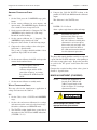
9 - Calibration
GENERAL
TEST SETUP
Complete calibration of the 5300 PA is beyond the
capabilities of most users. Magtrol, Inc. recommends
that the 5300 PA be returned to the factory for calibration
certifying the instrument to full specifications.
The recommended test setup for each phase is shown in
Figure 16.
NOTE:
However, this section includes Calibration Accuracy
Verification procedures and steps to make minor trimups of calibration.
NOTE:
Figure 16.
The same test setup is repeated
for each of the 3-phases.
The accuracy of the voltage and current standards used
for calibration should be at least four times the accuracy
of the 5300 PA specifications. The equipment shown
in this test setup meets this requirement.
To perform these steps, the
factory calibration seal will be
broken. This voids the factory
Calibration Certification that
comes with the 5300 PA.
To accurately measure AC power it is important that
the current source have a phase shifting control. With
such a phase adjustment, phase shift caused by incidental
circuit inductances can be compensated for by adjusting
the phase of the current wave form to be exactly in phase
(zero phase shift) with the voltage wave form. Sources
of incidental circuit inductance include the current shunts
within the 5300, output impedance of the calibrators,
impedance of the load and wiring inductance.
Calibration Verification Test Setup
(For Each Phase)
VARIABLE
PHAS
OUTPUT
E
PHASE
LOCK
IN
VOLTAGE CALIBRATOR
VOLTAGE CALIBRATOR
FLUKE 5700A OR
FLUKE 5100A OR
EQUIVALENT
FLUKE 5700A OR
EQUIVALENT
VOLTS
VOLTS, HIGH
LOW
OPTIONAL-FOR AMPS >2
TRANSCONDUCTANCE AMP.
FLUKE 5725A;5205A
GUIDELINE 7620A, OR
EQUIVALENT
LOW
CURRENT
HIGH
UUT
VOLTS
5300
(EACH PHASE)
HIGH
LOW
AMPS
(REF)
GND
INPUT
OUTPUT
EARTH
21
Magtrol Model 5300 Three Phase Power Analyzer
Chapter 9 - Calibration
Since the current calibrator output is usually a low
impedance with low compliance voltage, the 5300's
current measuring shunts are the circuit's major
resistance. Let's take a representative example and
compute the resulting phase shift:
VOLTS CALIBRATION CHECK φ 1
DC:
1. On the 5300 PA, press the 150 volts range pushbutton.
Let L = 10 µhenries (total of shunt, wiring, etc.)
2. Set the volts calibrator for zero volts DC and operate
mode.
Let RSHUNT = 0.011 Ohm; RWIRING = 0.01 Ohm
3. The 5300 VOLTS display should read zero +
0.0001% max of volts full scale range.
R = 0.011 + 0.01 = 0.021 Ohms
Let F = 60 Hz ∴ 2 π FL ≈ 0.004
θ Arctan (2 π FL /R) = Arctan (0.004 /0.021)
θ ≈ 11 degrees, or about 1.8 % measurement error. This
error can be eliminated by adjusting the calibrator's
variable phase shift control. This demonstrates the need
for care in making power analyzer calibration
measurements.
4. Set volts calibrator for + 150 volts DC.
5. The 5300 VOLTS display should read 150.0 volts.
Record the VOLTS readings.
6. Set the calibrator for - 150 volts DC and repeat the
above step. Record the VOLTS readings.
7. Repeat the above for the 300 and 600 volts ranges.
CALIBRATION VERIFICATION
Refer to Figure 16 for the recommended test setup. If
other test equipment is used, appropriately modify the
test steps for your equipment. Each of the 3-phases
(φ1, φ2, φ3) are identical and are individually tested.
The same procedure is used for each of the 3-phases.
Lethal voltages are present. Take
appropriate safety precautions.
8. Compare the above readings to the values given in
Section 2, Specifications.
The (+) and (-) readings should be within ± 2 least
significant digit (LSD) of each other.
AC:
Potentially lethal voltages are used in
the following test steps. Take
appropriate precautions to avoid
electrical shock. Refer to your calibrator
operator manual for operating
instructions. Because these calibrators
generate lethal voltages, extreme care is
necessary.
The three steps of the calibration verification are as
follows:
1. Volts Calibration Check
2. Amperes Calibration Check
3. Watts Calibration
Set both the VOLTS and AMPERES calibrators to
standby mode.
22
1. Set the volts calibrator for 60 Hz and repeat the
volts checks as outlined in the DC test above.
NOTE:
If a beat frequency effect is
experienced between the
calibrator output and the 60 Hz
power line frequency, try setting
the calibrator for 80 Hz instead of
60 Hz.
2. Set the volts calibrator to standby mode.
Magtrol Model 5300 Three Phase Power Analyzer
AMPERES CALIBRATION CHECK
DC:
1. On the 5300, press the 5 AMPERES range pushbutton.
2. Set the current calibrator for zero amperes and
operate mode. The AMPERES display should read
zero + 0.0001% max of range full scale.
3. Set the current calibrator for + 5 Amperes DC. The
AMPERES display should read 5.000 Amps.
Record the current readings.
Chapter 9 - Calibration
4. Compare the 5300 PA WATTS readout to the
product of VOLTS and AMPS from the calibrator's
output.
This difference is the WATTS error.
AC:
POWER = V × I × Cos θ
where = phase angle between volts and amps.
NOTE:
4. Set the current calibrator for - 5 Amperes. The
AMPERES display should read 5.000.
5. Repeat the above for the 25 and 100 Amp ranges.
6. Compare the above readings to the values given
in Section 2 - Specifications.
The (+) and (-) readings should be within ± 2 least
significant digit (LSD) of each other.
AC:
1. Set the current calibrator for 60 Hz. and repeat the
current checks outlined above.
NOTE:
If a beat frequency effect is
experienced between the
calibrator output and the 60 Hz
power line frequency, try setting
the calibrator for 80 Hz instead of
60 Hz.
2. Set the current calibrator to standby mode.
WATTS CALIBRATION CHECK
This step calls for the simultaneous application of
voltage and current to the 5300 PA.
Maximum true power is
delivered only when θ = zero
degrees (cos θ = 1). Therefore,
the volts calibrator variable phase
adjustment is set for zero phase
between the volts and amps at the
input to the 5300 PA. Refer to
the calibrator instruction manuals
for this adjustment procedure.
The phase shift control should be carefully set to provide
a peak 5300 PA WATTS indication, corresponding to
zero volts to amps phase angle. Repeat the procedure
as used for the DC power verification and record
readings.
Compare the recorded reading to the values given in
Section 2 - Specifications.
MINOR ADJUSTMENT (IF NEEDED)
NOTE:
All trim pot adjustments are
located on the 78B146 and
78B147 circuit boards of the
5300. See Figure 17 for trimpot
adjustment locations.
DC:
1. On the 5300, select a VOLTS and AMPERES
range.
2. Set the volts and current calibrators for a voltage
and current near the center of each selected range.
Lethal voltages are present. Take
appropriate safety precautions.
Switch the calibrators to OPERATE mode.
3. The WATTS readout should show a power that is
the product of the VOLTS and AMPS indications
( POWER = V × I ).
23
Chapter 9 - Calibration
Figure 17.
Magtrol Model 5300 Three Phase Power Analyzer
Trimpot Adjustment Locations
78B146
-R23
Ø -R25
Ø -R27
Ø -R21
78B147
Ø
Ø
Ø
-R29
-R26
Ø
-R24
-R21
Ø
-R18
Ø
78B146
-R23
Ø -R25
Ø -R27
Ø -R21
Ø
-R13
Ø
-R15
Ø
-R8
Ø
-R10
Ø
-R3
Ø
-R5
Ø
Ø
Ø2
-R13
Ø
-R15
Ø
-R8
-R13
Ø
-R10
Ø
Ø
Ø
Ø
Ø
-R10
Ø
-R3
Ø
-R5
-R29
-R26
Ø
-R24
-R21
Ø
-R18
Ø
Ø3
Ø
78B147
Ø
78B146
-R23
Ø -R25
Ø -R27
Ø -R21
78B147
Ø
Ø
Ø
Ø
-R24
-R21
Ø
-R18
Ø
-R13
Ø
-R10
Ø
Ø
Ø1
-R13
Ø
-R15
Ø
-R8
Ø
-R10
Ø
-R3
Ø
-R5
-R13
-R29
-R26
Ø
-R10
-R5
Ø
-R5
Ø
-R5
-R2
Ø
-R2
Ø
-R2
VOLTS ZERO
VOLTS SCALE FACTOR
1. Disable the auto zero function, refer to Special
Functions in Section 5.
1. Go to the 5300 VOLTS range(s) that need
adjustment.
2. Go to the 5300 VOLTS range that needs zero
adjustment.
2. Set the volts calibrator for an output equal to the
range maximum voltage.
3. Set the volts calibrator for zero volt DC output.
3. Adjust the trim pot(s) so the VOLTS display reads
the full scale voltage as shown below:
4. Adjust trim pot 78B146-R21 for zero (+ 0.0001%
max) VOLTS display reading.
This sets all voltage ranges - all ranges should be
zero + 0.0001% of range full scale.
For the 150 volt range, adjust 78B146-R27.
For the 300 volt range, adjust 78B146-R25.
For the 600 volt range, adjust 78B146-R23.
AMPERES ZERO
AMPERES SCALE FACTOR
1. Disable the auto zero function. See Section 5, CT/
PT Installation.
1. Go to the AMPERES range(s) that need adjustment.
2. Go to the 5300 AMPERES range(s) that need
adjustment.
2. Set the current calibrator DC output to the range
maximum current and adjust trim pot(s) so the
AMPERES display reads the full scale current:
3. Set the current calibrator for zero amp DC output.
For the 5 Amp. range, adjust 78B146-R3.
4. For the 5 amp range, adjust trim pot 78B146-R5,
25 amp range adjust trimpot 78B146-R10, and the
100 amp range adjust trimpot 78B146-R15 for zero
AMPERES display indication.
For the 25 Amp. range, adjust 78B146-R8.
24
For the 100 amp range, adjust 78B146-R13.
Magtrol Model 5300 Three Phase Power Analyzer
NOTE:
Chapter 9 - Calibration
Calibration on the 25 and 100
Amps ranges may have to be
done at less than full range scale,
depending on your calibration
equipment.
VOLTS BALANCE
1. Go to the 5300 PA 150 VOLTS range.
2. Set the voltage calibrator for + 150 volts DC output.
Note the VOLTS display reading.
3. Reverse the calibrator polarity to -150 volts DC. If
the plus to minus display readings differ by more
than ± 2 LSD, connect a digital voltmeter at
amplifier 78B147-U4 pin 14 and adjust trim pot
78B147-R10 for zero ± 0.1 millivolt dc.
CURRENT BALANCE
1. Go to the 5300 PA 5 amp. range
2. Set the current calibrator for + 5 Amps DC output.
3. Note the AMPERES display reading. Reverse the
calibrator polarity to - 5 Amps DC. If the plus and
minus display readings differ by more than ± 2 LSD,
connect digital voltmeter at amplifier 78B147-U1
pin 14 and adjust trim-pot 78B147-R2 for zero ±
0.1 millivolt DC.
WATTS SCALE FACTOR
1. Set the volts and current calibrators for 150 VDC
and 5 Amp DC output.
2. Adjust trim pot 78B147-R18 for 750.00 WATTS
display reading.
3. Confirm AC measurement accuracy by setting the
calibrators for 150 VRMS and 5 Amps RMS at 60
Hz. The WATTS display should read close to
750.00 watts and be within the specification
accuracy. See Section 2 - Specifications.
NOTE:
Adjust current calibrator's phase
shift control for zero phase angle
between volts and amps (peak the
watts indication) - see
"Calibration Verification--AC,"
Step 3.
25
c dp
ed
MSD
ab
digit 1
ed
g f
ed
g f
AMPS
c dp
ab
digit 2
c dp
ab
digit 3
c dp
ab
digit 4
LSD
ed
g f
c dp
ab
digit 5
MSD
ed
g f
ed
g f
ed
g f
VOLTS
c dp
ab
digit 6
c dp
ab
digit 7
C1
Com
+5
c dp
ab
digit 1
MSD
ed
g f
HP HDSP-5501
Common Anode
LED Displays
c dp
ab
digit 8
LSD
ed
g f
+
1
d5
d4
d3
d2
d1
g
e
f
d
a
c
b
dp
g
e
f
d
a
c
b
dp
d1
d2
d3
d4
d5
d6
d7
d8
26
g f
J7
ed
g f
c dp
ab
digit 2
c dp
ab
digit 3
WATTS
ed
g f
ed
g f
c dp
ab
digit 4
c dp
ab
digit 5
LSD
ed
g f
Appendix A
A:: Schematic Drawings
CIRCUIT BOARD 78B128 - LED DISPLAY
12
0
1
0
0
0
0
0
0
0
0
0
0
0
0
0
0
0
4
0
1
0
0
1
0
0
0
0
0
0
0
0
0
0
0
0
3
0
1
0
0
1
0
0
0
0
0
0
0
0
0
0
0
0
1
0
1
0
0
1
0
0
1
1
0
0
1
1
0
0
1
1
CODE B
0
0
1
0
0
1
0
1
0
1
0
1
0
1
0
1
0
1
U10
3
4
5
6
2
7
9
10
3
4
5
6
2
7
9
10
11
ROM CODE E000
=8192
FFFF
INT RAM 80 TO FF
EXT. RAM 2000 TO
27FF (NON VOL.)
PIA 8000 DDRA/ORA
8001 CRA
8010 DDRB/ORB
8011 CRB
GPIA C000 R0
C001 R1
C002 R2
C003 R3
COO4 R4
C005 R5
C006 R6
C007 R7
17
S R 1-4
8
S R5
MC3447
22
B1 2 D1
21
B2 4 D2
20
B3 6 D3
19
B4 8 D4
23
B0 srq D0
18
B5 rfd D5
16
B6 atn D6
15
B7 ren D7
MC3447
22
B1 1 D1
21
B2 3 D2
20
B3 5 D3
19
B4 7 D4
23
B0 dav D0
18
B5 dac D5
16
B6 eoi D6
15
B7 ifc D7
1
S R0 S R6
17
S R 1-4
8
S R5
P10 TO P13 = CODE B DATA
P14 = D.P.
P15 TO P17 = DIGIT ADDRESS
2
0
1
0
0
1
0
0
0
0
0
0
0
0
1
1
1
1
+5
U11
0 1 2 3 4 5 6 7 8 9 - E H L P (BLANK)
DECIMAL 0 1 2 3 4 5 6 7 8 9 10 11 12 13 14 15
$6000
$4000
ADDRESS BUS (AD15-0)
11 10 9 8 7 6 5
0 0 0 0 0 0 0
1 1 1 1 1 1 1
0 0 0 0 1 0 0
0 0 0 0 0 0 0
0 1 1 1 1 1 1
0 0 0 0 0 0 0
0 0 0 0 0 0 0
0 0 0 0 0 0 0
0 0 0 0 0 0 0
0 0 0 0 0 0 0
0 0 0 0 0 0 0
0 0 0 0 0 0 0
0 0 0 0 0 0 0
0 0 0 0 0 0 0
0 0 0 0 0 0 0
0 0 0 0 0 0 0
0 0 0 0 0 0 0
P17 P16 P15 DIGIT
0
AMPS 1000
0
0
AMPS 100
1
0
0
AMPS 10
1
0
0
AMPS 1
1
1
0
1
VOLTS 1000
0
0
VOLTS 100
0
1
1
0
VOLTS 10
1
1
1
1
VOLTS 1
1
0
0
WATTS 10000
0
WATTS 1000
0
1
0
WATTS 100
0
0
1
1
WATTS 10
0
1
0
0
WATTS 1
1
15 14 13
1 1 1
1 1 1
0 0 0
0 0 1
0 0 1
1 0 0
1 0 0
1 0 0
1 0 0
1 1 0
1 1 0
1 1 0
1 1 0
1 1 0
1 1 0
1 1 0
1 1 0
COM
J2
COM
J3
sw1
sw3
sw5
sw4
sw2
AD0
AD2
AD4
AD3
AD1
AD7
AD6
AD5
AD4
AD3
AD2
AD1
AD0
A0
A1
A2
U12
74HC367
2 A1 Y1 3
4 A2 Y2 5
6 A3 Y3 7
12 A5 Y5 11
14 A6 Y6 13
1 G1
15 G2
U9
MC68488
3
36
IB0
CS
34
37
RS0
IB2
38
32
IB4
RS1
30
39
IB6
RS2
16
19
DAV RES
17
40
DAC IRQ
25
6
EOI
E
21
5
IFC
RW
28
14
D7
T R1
27
13
D6
T R2
12
35
IB1
D5
11
33
IB3
D4
31
10
IB5
D3
29
9
IB7
D2
23
8
SRQ
D1
18
7
RFD
D0
26
4
ATN ASE
22
REN
D0
D1
D2
D3
DP
DA0
DA1
DA2
1
2
3
4
5
6
7
8
9
10
11
12
13
14
+5
1
2
3
4
5
6
7
8
9
10
11
12
13
14
Vss
Seg a
Seg g
Seg d
Seg f
DIGIT 3
DIGIT 6
DIGIT 7
DIGIT 4
Vdd
DIGIT 8
DIGIT 5
DIGIT 2
DIGIT 1
COM
U1
28
27
26
25
24
23
22
21
20
19
18
17
16
15
28
27
26
25
24
23
22
21
20
19
18
17
16
15
27pf
Vss
Seg a
Seg g
Seg d
Seg f
DIGIT 3
DIGIT 6
DIGIT 7
DIGIT 4
Vdd
DIGIT 8
DIGIT 5
DIGIT 2
DIGIT 1
ICM7218C
U2
Seg c
Seg e
Seg b
D.P.
DA0
DA1
DPin
WRITE
MODE
DA2
D1
D0
D2
D3
Seg c
Seg e
Seg b
D.P.
DA0
DA1
DPin
WRITE
MODE
DA2
D1
D0
D2
D3
27pf
4MHz
1N482x2
+ 47
ICM7218C
4.7kx5
COM
MC6803
X1
E
EX2 SC1
NMI SC2
IRQ
P30
RST P31
P32
8 P20
P33
9 P21
P34
10 P22
P35
11 P23
P36
12 P24
P37
13 P10
P40
14 P11
P41
15 P12
P42
16 P13
P43
17 P14
P44
18 P15
P45
19 P16
P46
20 P17
P47
2
3
4
5
6
AD0
AD1
AD2
AD3
AD4
AD5
AD6
AD7
A8
A9
A10
A11
A12
A13
A14
A15
U8
40
39
38
37
36
35
34
33
32
31
30
29
28
27
26
25
24
23
22
A0
A1
A2
A3
A4
A5
A6
A7
A8
A9
A10
A0
A1
A2
A3
A4
A5
A6
A7
A8
A9
A10
A11
A12
AD0
AD1
AD2
AD3
AD4
AD5
AD6
AD7
22
20
U5
A0
A1
A2
A3
A4
A5
A6
A7
AD0
AD1
AD2
AD3
AD4
AD5
AD6
AD7
1
+
AD0
AD1
AD2
AD3
AD4
AD5
AD6
AD7
U4
11
12
13
15
16
17
18
19
U7
DS1220
8
9
A0 DQ0
7
10
A1 DQ1
11
6
DQ2
A2
5
13
A3 DQ3
4
14
A4 DQ4
3
15
A5 DQ5
2
16
A6 DQ6
17
1
DQ7
A7
23
CE 18
A8
22
20
A9 OE
19
21
A10 WE
2764
10
A0 DQ0
9
A1 DQ1
8
A2 DQ2
7
A3 DQ3
6
A4 DQ4
5
A5 DQ5
4
A6 DQ6
3
A7 DQ7
25
A8
24
A9
21
A10
23
G
A11
2
E
A12
74HC373
2
3
1D 1Q
5
4
2D 2Q
6
7
3D 3Q
9
8
4D 4Q
13
12
5D 5Q
15
14
6D 6Q
16
17
7D 7Q
18
19
8D 8Q
11
LE
D5
D4
D3
D2
D1
g
e
f
d
a
c
b
DP
g
e
f
d
a
c
b
DP
D1
D2
D3
D4
D5
D6
D7
D8
J7
A13
A14
A15
AD0
AD1
AD2
AD3
AD4
AD5
AD6
AD7
A0
A1
1
2
3
6
4
5
U6
74F138
A
Y0
B
Y1
C
Y2
G1 Y3
G2A Y4
G2B Y5
Y6
Y7
15
14
13
12
11
10
9
7
U3
MC6821
33
2
D0
PA0
32
3
D1
PA1
31
4
D2
PA2
30
5
D3
PA3
29
6
D4
PA4
28
7
D5
PA5
27
8
D6
PA6
26
9
D7
PA7
36
40
RS0 CA1
35
39
RS1 CA2
10
PB0
11
PB1
23
12
CS2 PB2
25
13
PB3
E
14
21
R/ W PB4
15
38
IRQA PB5
16
37
IRQB PB6
17
34
RES PB7
18
CB1
19
CB2
U
3
4
5
6
7
8
9
10
11
12
Note:
COM
12kx2
PB0
PB1
PB2
PB3
PB4
PB5
PB6
PB7
PA0
PA1
PA2
PA3
PA4
PA5
PA6
PA7
LL2
LL1
RL
FCT
RNG
RES
DAV
CT
1 +
COM
1
14
12
8
1,10
1
1,2
8
+5
20,22,24
1,27,28
24
16
20
7,21
20
16
All capacitors in uF
All resistors in OHMS
Unless otherwise noted
PB7
PB6
PB5
PB4
PB3
PB2
PB1
PB0
PA7
PA6
PA5
PA4
PA3
PA2
PA1
PA0
J1
E
+5
COM
Magtrol Model 5300 Three Phase Power Analyzer
Appendix A: Schematic Drawings
CIRCUIT BOARD 78B145 - DIGITAL READOUT & MPU
27
Appendix A: Schematic Drawings
Magtrol Model 5300 Three Phase Power Analyzer
CIRCUIT BOARD 78B146 - ANALOG INPUT BOARD
-15V
R5
5A SHUNT
P1
34
R1
CR1
FDH300
+15V
10.0K
CR2
FDH300
R2
200K
14
x10
15
x100 U7
10
9
x200 INA110KP
x500
6
+
8 C2
+ 7 C3
.1
1
13
CR3
R3 12
FDH300 C1
100 16
-15V
180pF
11
R4
CR4
3
FDH300
80.6
2
10.0K
.1
-15V
P1
29
AMPS
P1
23
A5 COM
P1
25
A25 COM
+15V
-15V
R10
25A SHUNT
P1
36
R6
CR5
FDH300
+15V
10.0K
CR7
R8
FDH300 C4
100
-15V
180pF C25
R9
CR8
180pF
FDH300
80.6
CR6
FDH300
R7
U11
16
1
15
2
3
14
13
4
Vdd
Vss
5
12
GND
6
11
7
10
8
9
200K
14
1
13
12
16
11
3
2
-15V
x10
15
C22
x100 U8
10
9
x200 INA110KP
.1
x500
6
+
8 C5
+ 7 C6
.1
10.0K
+15V
C23
.1
ADG201HSKN
.1
-15V
+15V
-15V
R15
P1
100A SHUNT 38
R11
CR9
FDH300
+15V
10.0K
P1
SHUNT COM 32
CR10
FDH300
R12
200K
14
x10
15
x100 U9
10
9
x200 INA110KP
x500
6
+
8 C8
+ .1
7 C9
1
13
CR11
R13 12
FDH300 C7
100 16
-15V
560pF
11
R14
CR12
3
FDH300
2
80.6
10.0K
.1
-15V
+15V
5V
-15V
V HIGH
R19
R39
1.5M
V LOW
P1
31
CR13
FDH300
+15V
R34 10.0K
15.8K
R38
15.8K R20
R40
1.5M
CR15
FDH300
-15V
CR16
FDH300
CR14
FDH300
R26
1
2
3
4
Vss
C20 5 GND
6
.1
7
8
-15V
x10
15
10
x100 U10
9
x200 INA110KP
x500
6
+
8 C10
+ 7 C11
.1
10.0K
R27 150V
-15V
4.64K 5K
U12
16
15
14
13
Vdd
12
11
10
9
R24
+15V
C21
.1
R29
200K
14
1
13
12
16
11
3
2
5
4
6
2K
R21
P1
33
R28
5
4
6
2K
R30
5
4
6
2K
R31
5
4
6
2K
.1
+15V
R32
5
4
6
2K
R25 300V
23.2K 10K
R33
R22
2K
R23 600V
5
4
6
301K 100K
1
2
4N36
U1
1
2
4N36
U2
1
2
4N36
U3
1
2
4N36
U4
1
2
4N36
U5
1
2
4N36
U6
R16
P1
A100 COM
27
P1
VOLTS
37
P1
VOLTS COM
35
P1
45 5A SELECT
470
R17
P1
47 25A SELECT
470
R18
P1
49 100A SELECT
470
R35
P1
46 150V SELECT
470
R36
P1
48 300V SELECT
470
R37
P1
50 600V SELECT
470 P1
43 CHASSIS COM
ADG201HSKN
LM340T5
AC LINE
P1
2
1
T1 7
J1
3
4
J2
9
10
AC LINE
P1
1
J3
FOR 240 VOLT OPERATION JUMP J2 ONLY
LM340T15
BR1
+
PD05
6
12
14A-10R-36
FOR 120 VOLT OPERATION JUMP J1 AND J3
P1
15 +5V
+
C19
+
.1
1
+15V
P1
17 +15V
P1
16 SIGNAL COM
P1
18 POWER COM
-15V
P1
19 -15V
VR1
C12 C14
1000
+
1
C13
1000
C15
.1
C17
C16
1 +
.1
VR2
LM320T15
28
5V
VR3
C18
P1
+15V 17
P1
-15V 19
P1
+5V 15
P1
POWER COM 18
P1
SIGNAL COM 16
P1
VOLTS COM 35
P1
VOLTS 37
P1
A5 COM 23
P1
A25 COM 25
P1
A100 COM 27
P1
AMPS 29
-15V
1.69K
R33
+5V
+ C35 C36
1 + 1
+15V
+ C37
1
+15V
CR3
1N821
6
U12
3
+
OP7
C18 4
.1
-15V
10.0K
+15V
7
17.8K
-
R35
-15V
R34
2
R47
1
2
3
4
5
6
7
1
2
3
4
5
6
7
1
2
3
4
5
6
7
24.3K
U1
R1
10.0K
-15V
10.0K
R37
10.0K
-15V
10.0K
R42
R41
+V
C41
.1
-15V
C39
.1
-15V
+
STR
GND +V
6
7
8
249K
U16
+
STR
GND +V
6
7
8
5
4
-V BAL
C34
.1
LM311N
2
C23
.1 3
1
R43
5
4
-V BAL
C21
.1
LM311N
2
C20
.1 3
1
249K
U13
R38
R5
20K
+15V
C3
+15V
C8
R44
1.5K
+15V
R39
1.5K
1
C24 2
.1
4N36
U15
5
4
6
5
4
6
5V
5V
R24
20K
U6
+15V
C13
6N137
C29
.01
+15V 1
2
3
4
U3
6N137
+15V
+15V 1
2
3
4
C27
.01
+15V
8
7
6
5
8
7
6
5
R45
1.2K
R40
1.2K
C25
.1
C22
.1
VFC320CG
R23
U9
10M .001
R22
1
14
-IN
+IN
2
13
34.8K
Vo
12
-15V 3
+V
11
4
-V COM
5
10
C30
C COMP
6
9
C14
.01
7
8
330pf
Fo
-15V
20K
1
5
6
U8
3
LF351
+
7
4
+15V
-15V
2
1
C19 2
.1
4N36
U14
C11 100K
.47
R19
-15V
.1
R21
301K C12
R20
1.5K
VFC320CG
R15
R12
U5
10M .001
1
14
-IN
+IN
2
13
34.8K
Vo
12
+15V
-15V 3
+V
4
11
-V COM
C28
10
5
C COMP
C42
9
C9
6
.01
.1
330pf
8
7
Fo
20K
R11
-15V
R13
1.5K
VFC320CG
R7
R4
U2
10M .001
R3
14
1
-IN +IN
2
13
34.8K
Vo
12
+15V
-15V 3
+V
4
11
-V COM
C26
10
5
COMP
C
C40
C4
9
6
.01
.1
330pf
8
7
Fo
-15V
+15V
14 +15V
13
R17 R18
12
OUT
11 200K 20K
Z1
10
Z2
9
8 -15V
-V
U7
AD534LD
Y1
Y2
SF
X1
X2
BFi
BFo 14
Vin 13
12
COM
OFFS +V 11
CS
-V 10
DENi RMSo 9
dBo
Cav 8 C7
+
AD637KQ
2.2
24.3K
U4
R9
BFo 14
Vin 13
12
COM
OFFS +V 11
CS
-V 10
DENi RMSo 9
dBo Cav 8 C2
+
AD637KQ
2.2
BFi
R36
C6
+
2.7
50K 750K
+15V
R10
R46
2.7
50K 750K
-15V
R2
+15V
C1
+
C10
.1
5V
C5
.1
5V
C31
.01
+15V
R16
470
R8
470
R29
20K
+15V
C15
VFC320CG
R28
U10
10M .001
R26 R27
1
+IN 14
-IN
2
20K 32.4K
Vo 13
-15V 3
+V 12
11
4
-V COM
5
10
C32
C COMP
6
C16
9
.01
7
8
330pf
Fo
-15V
+5V
U11
1
2
3
CR2 4
1N4148
6N137
1N4148 R31
470
R25 R30
820 820 CR1
+15V
C33
.01
+15V
8
7
6
5
+
R32
470
P1
49 +5V
C38
1 P1
47 CHASSIS COM
5V
VOLTS OL
WATTS OUT
VOLTS OUT
AMPS OUT
P1
45 AMPS OL
P1
44
C17
.1 P1
50
5V
P1
48
P1
46
Magtrol Model 5300 Three Phase Power Analyzer
Appendix A: Schematic Drawings
CIRCUIT BOARD 78B147 - CONVERTER BOARD
29
Appendix A: Schematic Drawings
Magtrol Model 5300 Three Phase Power Analyzer
CIRCUIT BOARD 78B149 - SWITCHBOARD
SW1
FRONT VIEW
SW2
SW3
LEFT
RIGHT
C1
J4
R1
200
30
SW4
R2
200
R3
200
R4
200
Magtrol Model 5300 Three Phase Power Analyzer
Appendix A: Schematic Drawings
CIRCUIT BOARD 78B153 - SWITCH INTERFACE
J1
E
J5
PA0
PA1
PA2
PA3
PA4
PA5
PA6
PA7
.001
PA0
PA1
PA2
PA3
PA4
PA5
PA6
PA7
.001
.001
PA0
PA1
PA2
PA3
PA4
PA5
PA6
PA7
74HC573
2
19
1Q
1D
18
3
2Q
2D
17
4
3D
3Q
16
5
4Q
4D
15
6
5Q
5D
14
7
6D
6Q
13
8
7D
7Q
12
9
8Q
8D
11
LE U3
H LED
AVG
74HC573
PF
19
2
1D
1Q
ØV
3
18
2Q
2D
17
4
3D
3Q
16
5
4Q
4D
15 Ø1 LED
6
5Q
5D
14
Ø2
7
6Q
6D
8
13
Ø3
7D
7Q
9
12 3ØKW
8D
8Q
11
LE U4
+5
Hold Switch
AVG
PF
ØV
J4 Function
2
3
4
5
6
7
8
9
1
J4 Phase
Ø1 Switch
Ø2
Ø3
3ØKW
J4 Amps
74HC573
2
5
5
19
1D
1Q
3
18
25
25
2D
2Q
4
17
100
3D
3Q
Auto Switch
5
16 100
4D
4Q
6
15
5D
5Q
7
14
A LED
6D
6Q
8
13
7D
7Q
12
9
8D
8Q
150
150
11
LE U6
300
300
600
600
A LED
A Sw
All capacitors in uF
All resistors in OHMS
Unless otherwise noted
U
+5
COM
3,4,6
20
1,10
5,7
11,20
10
8,9
16
1,8,9
10
16
8,9
1
R2
150
R1
300
5
600 25
CT 100
COM
Note:
COM
COM
J4 Volts
Range
5
25
100
COM
R1
1
0
0
U1 12kx8
U2 12kx8
2
3
4
5
6
7
8
9
1
74HC573
19
1D
1Q
18
2D
2Q
17
3D
3Q
16
4D
4Q
15
5Q
5D
14
6D
6Q
13
7Q
7D
12
8D
8Q
OC U5
74HC573
19
1D
1Q
18
2D
2Q
17
3D
3Q
16
4Q
4D
15
5D
5Q
14
6D
6Q
13
7D
7Q
12
8D
8Q
OC U7
.001
PA0
PA1
PA2
PA3
PA4
PA5
PA6
PA7
PA0
PA1
PA2
PA3
PA4
PA5
PA6
PA7
PA7
PA6
PA5
PA4
PA3
PA2
PA1
PA0
LL2
LL1
RL
RNG
FCT
RES
DAV
CT
+5
CD4518
1
CK
2
EN
7
RST
6
U10a Q3
CD4518
10
EN
15
RST
14
U10b Q3
CD4518
2
EN
7
RST
6
U9a Q3
CD4518
.001
10
EN
15
RST
14
U9b Q3
CD4518
2
EN
7
RST
6
U8a Q3
CD4518
11
Q0
10
EN
15
RST
U8b
R2
1
1
0
31
Appendix A: Schematic Drawings
Magtrol Model 5300 Three Phase Power Analyzer
CIRCUIT BOARD 78B154 - COUNTERS BOARD
A3Fin
V3Fin
W3Fin
V3OL
A3OL
J6
1
74HC573
2 1D 1Q 19
3 2D 2Q 18
4 3D 3Q 17
5 4D 4Q 16
6 5D 5Q 15
7 6D 6Q 14
8 7D 7Q 13
9 8D 8Q 12
11 LE
1 OC
9 CK Q0 11
10 EN Q1 12
15 RST Q2 13
Q3 14
U9
U15
74HC573
2 1D 1Q 19
3 2D 2Q 18
4 3D 3Q 17
5 4D 4Q 16
6 5D 5Q 15
7 6D 6Q 14
8 7D 7Q 13
9 8D 8Q 12
11 LE
1 OC
4520
1 CK Q0 3
2 EN Q1 4
7 RST Q2 5
Q3 6
9 CK Q0 11
10 EN Q1 12
15 RST Q2 13
Q3 14
U8
1
2
7
U14
74HC573
2 1D 1Q 19
3 2D 2Q 18
4 3D 3Q 17
5 4D 4Q 16
6 5D 5Q 15
7 6D 6Q 14
8 7D 7Q 13
9 8D 8Q 12
11 LE
1 OC
4520
3
CK Q0
4
EN Q1
5
RST Q2
6
Q3
9
11
CK Q0
10
12
EN Q1
15
13
RST Q2
14
Q3
U7
1
2
7
U13
74HC573
2 1D 1Q 19
3 2D 2Q 18
4 3D 3Q 17
5 4D 4Q 16
6 5D 5Q 15
7 6D 6Q 14
8 7D 7Q 13
9 8D 8Q 12
11 LE
1 OC
4520
3
CK Q0
4
EN Q1
5
RST Q2
6
Q3
9
11
CK Q0
10
12
EN Q1
15
13
RST Q2
14
Q3
U6
1
2
7
U12
74HC573
2 1D 1Q 19
3 2D 2Q 18
4 3D 3Q 17
5 4D 4Q 16
6 5D 5Q 15
7 6D 6Q 14
8 7D 7Q 13
9 8D 8Q 12
11 LE
1 OC
4520
3
CK Q0
4
EN Q1
5
RST Q2
6
Q3
9
11
CK Q0
10
12
EN Q1
15
13
RST Q2
14
Q3
U5
1
2
7
U11
74HC573
2 1D
19
1Q
3 2D
18
2Q
4 3D
17
3Q
5 4D
16
4Q
6 5D
15
5Q
7 6D
14
6Q
8 7D
13
7Q
12
9 8D
8Q
11 LE
1 OC
4520
3
CK Q0
4
EN Q1
5
RST Q2
6
Q3
9
CK Q0
10
EN Q1
15
RST Q2
Q3
U4
11
12
13
14
CL
V2OL
A2OL
A1Fin
V1Fin
W1Fin
V1OL
A1OL
+5
4520
1 CK Q0 3
2 EN Q1 4
7 RST Q2 5
Q3 6
CD4520
EN
Qx
1
INC
0
INC
X
X
X
X
1
X
A2Fin
V2Fin
W2Fin
PA0
PA1
PA2
PA3
PA4
PA5
PA6
PA7
PA0
PA1
PA2
PA3
PA4
PA5
PA6
PA7
1
2
7
4520
CK Q0
EN Q1
RST Q2
Q3
9 CK Q0
10 EN Q1
15 RST Q2
Q3
U21
1
2
7
4520
CK Q0
EN Q1
RST Q2
Q3
3
4
5
6
11
12
13
14
3
4
5
6
9 CK Q0 11
10 EN Q1 12
15 RST Q2 13
Q3 14
U20
PA0
PA1
PA2
PA3
PA4
PA5
PA6
PA7
1
2
7
4520
CK Q0
EN Q1
RST Q2
Q3
3
4
5
6
9 CK Q0 11
10 EN Q1 12
15 RST Q2 13
Q3 14
U19
PA0
PA1
PA2
PA3
PA4
PA5
PA6
PA7
1
2
7
4520
CK Q0 3
EN Q1 4
RST Q2 5
6
Q3
9 CK Q0 11
10 EN Q1 12
15 RST Q2 13
Q3 14
U18
PA0
PA1
PA2
PA3
PA4
PA5
PA6
PA7
4520
1 CK Q0 3
2 EN Q1 4
7 RST Q2 5
Q3 6
9 CK Q0 11
10 EN Q1 12
15 RST Q2 13
Q3 14
U17
PA0
PA1
PA2
PA3
PA4
PA5
PA6
PA7
4520
1 CK Q0
2 EN Q1
7 RST Q2
Q3
3
4
5
6
9 CK Q0 11
10 EN Q1 12
15 RST Q2 13
Q3 14
U16
U10
74HC573
2 1D 1Q 19
3 2D 2Q 18
4 3D 3Q 17
5 4D 4Q 16
6 5D 5Q 15
7 6D 6Q 14
8 7D 7Q 13
9 8D 8Q 12
11 LE
1 OC
U27
74HC573
2 1D 1Q 19
3 2D 2Q 18
4 3D 3Q 17
5 4D 4Q 16
6 5D 5Q 15
7 6D 6Q 14
8 7D 7Q 13
9 8D 8Q 12
11 LE
1 OC
U26
74HC573
2
19
1D 1Q
3
18
2D 2Q
4
17
3Q
3D
5
16
4D 4Q
6
15
5D 5Q
7
14
6D 6Q
8
13
7D 7Q
9
12
8Q
8D
11
LE
1
OC
U25
74HC573
2
19
1D 1Q
3
18
2D 2Q
4
17
3D 3Q
5
16
4Q
4D
6
15
5D 5Q
7
14
6D 6Q
8
13
7D 7Q
9
12
8D 8Q
11
LE
1
OC
U24
74HC573
2
19
1D 1Q
3
18
2D 2Q
4
17
3D 3Q
5
16
4D 4Q
6
15
5Q
5D
7
14
6D 6Q
8
13
7D 7Q
9
12
8D 8Q
11
LE
1
OC
U23
74HC573
2
19
1D 1Q
3
18
2D 2Q
4
17
3D 3Q
5
16
4D 4Q
6
15
5D 5Q
7
14
6D 6Q
8
13
7D 7Q
9
12
8D 8Q
11
LE
1
OC
U22
PA0
PA1
PA2
PA3
PA4
PA5
PA6
PA7
PA0
PA1
PA2
PA3
PA4
PA5
PA6
PA7
1
2
7
4520
CK Q0
EN Q1
RST Q2
Q3
9 CK Q0
10 EN Q1
15 RST Q2
Q3
U33
1
2
7
4520
CK Q0
EN Q1
RST Q2
Q3
3
4
5
6
11
12
13
14
3
4
5
6
9 CK Q0 11
10 EN Q1 12
15 RST Q2 13
Q3 14
U32
PA0
PA1
PA2
PA3
PA4
PA5
PA6
PA7
1
2
7
4520
CK Q0
EN Q1
RST Q2
Q3
3
4
5
6
9 CK Q0 11
10 EN Q1 12
15 RST Q2 13
Q3 14
U31
PA0
PA1
PA2
PA3
PA4
PA5
PA6
PA7
1
2
7
4520
CK Q0
EN Q1
RST Q2
Q3
3
4
5
6
9 CK Q0 11
10 EN Q1 12
15 RST Q2 13
Q3 14
U30
PA0
PA1
PA2
PA3
PA4
PA5
PA6
PA7
1
2
7
4520
CK Q0
EN Q1
RST Q2
Q3
3
4
5
6
9 CK Q0 11
10 EN Q1 12
15 RST Q2 13
Q3 14
U29
PA0
PA1
PA2
PA3
PA4
PA5
PA6
PA7
1
2
7
4520
3
CK Q0
4
EN Q1
5
RST Q2
6
Q3
9
CK Q0
10
EN Q1
15
RST Q2
Q3
U28
11
12
13
14
74HC573
D
OC LE
L
H
H
L
H
L
L
L
X
H X
X
74HC573
19
2
1D 1Q
18
3
2D 2Q
17
4
3D 3Q
5
16
4D 4Q
6
15
5D 5Q
7
14
6D 6Q
8
13
7D 7Q
9
12
8D 8Q
11
LE
1
OC
U39
74HC573
2
19
1D 1Q
3
18
2D 2Q
4
17
3D 3Q
5
16
4D 4Q
6
15
5D 5Q
7
14
6D 6Q
8
13
7D 7Q
12
9
8D 8Q
11
LE
1
OC
U38
74HC573
2
19
1D 1Q
3
18
2D 2Q
4
17
3D 3Q
5
16
4D 4Q
6
15
5D 5Q
7
14
6D 6Q
8
13
7D 7Q
9
12
8D 8Q
11
LE
1
OC
U37
74HC573
2
19
1D 1Q
3
18
2D 2Q
4
17
3D 3Q
5
16
4D 4Q
6
15
5D 5Q
7
14
6D 6Q
8
13
7D 7Q
9
12
8D 8Q
11
LE
1
OC
U36
74HC573
2
19
1D 1Q
3
18
2D 2Q
4
17
3D 3Q
5
16
4D 4Q
6
15
5D 5Q
7
14
6D 6Q
8
13
7D 7Q
9
12
8D 8Q
11
LE
1
OC
U35
74HC573
2
19
1D 1Q
3
18
2D 2Q
4
17
3D 3Q
5
16
4D 4Q
6
15
5D 5Q
7
14
6D 6Q
8
13
7D 7Q
12
9
8D 8Q
11
LE
1
OC
U34
Q
H
L
Qo
Z
PA0
PA1
PA2
PA3
PA4
PA5
PA6
PA7
AMPS
PA0
PA1
PA2
PA3
PA4
PA5
PA6
PA7
PA0
PA1
PA2
PA3
PA4
PA5
PA6
PA7
VOLTS
PA0
PA1
PA2
PA3
PA4
PA5
PA6
PA7
PA0
PA1
PA2
PA3
PA4
PA5
PA6
PA7
WATTS
PA0
PA1
PA2
PA3
PA4
PA5
PA6
PA7
J1
74HC154
0
A
1
B
2
3
C
4
D
18 G1 5
19 G2 6
7
8
9
10
11
12
13
14
15
U3
23
22
21
20
Note:
All capacitors in uF
All resistors in ohms
Unless otherwise noted
U
1
2,3
4,5,6,7
8,9,16,17
18,19,20
21,28,29
30,31
32,33
10,11,12
13,14,15
22,23,24
25,26,27
34,35,36
37,38,39
32
+5
14
24
16
COM
7,9
12
8
20
10
1
2
3
4
5
6
7
8
9
10
11
13
14
15
16
17
74HC154
0
1
2
3
4
5
6
7
8
9
10
11
12
13
14
15
U2
23
A
22
B
21
C
20
D
18
G1
19
G2
+5
1
2
3
U1 74HC04
4
5 5
6
3
6
7 1
2
8
9 11
10
13
10
11
13
14
15
16
17
4
12
PB7
PB6
PB5
PB4
PB3
PB2
PB1
PB0
PA7
PA6
PA5
PA4
PA3
PA2
PA1
PA0
1
LL2
LL1
RL
RNG
FCT
RES
DAV
Magtrol Model 5300 Three Phase Power Analyzer
Appendix A: Schematic Drawings
CIRCUIT BOARD 78B175
Line
T1
120
6
7
4
9
3
10
BR1
240
120
Neu
I
PD05
1
12
14A-20-10
+5V
(Heatsink
7805 to chassis)
C1
4700uF
25V
C2
1uF
C
O
C3
1uF
C4
.1uF
Com
33
Magtrol Limited W
arranty
Warranty
Magtrol, Inc. warrants its products to be free from defects in material and workmanship under normal use and
service for a period of one (1) year from the date of shipment. Software is warranted to operate in accordance with
its programmed instructions on appropriate Magtrol instruments. This warranty extends only to the original purchaser
and shall not apply to fuses, computer media, or any other product which, in Magtrol’s sole opinion, has been
subject to misuse, alteration, abuse or abnormal conditions of operation or shipping.
Magtrol’s obligation under this warranty is limited to repair or replacement of a product which is returned to the
factory within the warranty period and is determined, upon examination by Magtrol, to be defective. If Magtrol
determines that the defect or malfunction has been caused by misuse, alteration, abuse or abnormal conditions of
operation or shipping, Magtrol will repair the product and bill the purchaser for the reasonable cost of repair. If the
product is not covered by this warranty, Magtrol will, if requested by purchaser, submit an estimate of the repair
costs before work is started.
To obtain repair service under this warranty, purchaser must forward the product (transportation prepaid) and a
description of the malfunction to the factory. The instrument shall be repaired at the factory and returned to purchaser,
transportation prepaid. MAGTROL ASSUMES NO RISK FOR IN-TRANSIT DAMAGE.
THE FOREGOING WARRANTY IS PURCHASER’S SOLE AND EXCLUSIVE REMEDY AND IS IN LIEU OF
ALL OTHER WARRANTIES, EXPRESSED OR IMPLIED, INCLUDING BUT NOT LIMITED TO ANY IMPLIED
WARRANTY OF MERCHANTABILITY, OR FITNESS FOR ANY PARTICULAR PURPOSE OR USE.
MAGTROL SHALL NOT BE LIABLE FOR ANY SPECIAL, INDIRECT, INCIDENTAL, OR CONSEQUENTIAL
DAMAGES OR LOSS WHETHER IN CONTRACT, TORT, OR OTHERWISE.
CLAIMS
Immediately upon arrival, purchaser shall check the packing container against the enclosed packing list and shall,
within thirty (30) days of arrival, give Magtrol notice of shortages or any nonconformity with the terms of the order.
If purchaser fails to give notice, the delivery shall be deemed to conform with the terms of the order.
The purchaser assumes all risk of loss or damage to products upon delivery by Magtrol to the carrier. If a product is
damaged in transit, PURCHASER MUST FILE ALL CLAIMS FOR DAMAGE WITH THE CARRIER to obtain
compensation. Upon request by purchaser, Magtrol will submit an estimate of the cost to repair shipment damage.