1
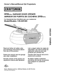
Owner's Manual/Manual Del Propietario
RRFTSMRN I
1/2 HP
315MHz GARAGE DOOR OPENER
ABRIDOR DE PUERTA DE COCHERA
For Residential
3|5MHz
Use Only
Model • 139.53930DM
m
Z
G3
O_
m
O_
'13
Z_
0
Read and follow all safety rules
and operating instructions before
first use of this product.
Leer y seguir todas las reglas de
seguridad y las instrucciones de
operacion antes de usar este
producto por primera vez.
Fasten the manual near the garage
door after installation.
Guardar este manual cerca de la
puerta de la cochera.
Periodic checks of the opener are
required to ensure safe operation.
Se deben realizar revisiones
periodicas del abridor de puertas
para asegurar su operacion
segura.
c@us
Sears,
Roebuck
and Co., Hoffman
www.sears.com/craftsman
Estates,
IL 60179 U.S.A
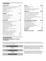
TABLE
OF CONTENTS
Introduction
2- 7
Adjustment
27-29
Safety symbol and signal word review ..............
2
Adjust the travel limits .........................
27
Preparing your garage door ......................
Tools needed .................................
3
3
Adjust the force ..............................
28
Test the safety reversal system ..................
29
Test The Protector System <_.....................
29
Planning
..................................
4-5
Carton inventory ...............................
6
Hardware inventory ............................
7
Assembly
8-11
Assemble the rail and install the trolley .............
Fasten the rail to the motor unit ...................
8
9
Operation
30-34
Operation safety instructions ....................
30
Using your garage door opener ..................
30
Using the wall-mounted
31
Door Control .............
To open the door manually ......................
31
Install the idler pulley ...........................
Install the chain/cable ..........................
9
10
Care of your garage door opener .................
32
Having a problem? ............................
33
Tighten the chain .............................
11
Diagnostic chart ..............................
34
Installation
11-26
Installation safety instructions
...................
Programming
35-36
11
To add or reprogram a hand-held remote control ....
35
Determine the header bracket location ............
12
To erase all codes ............................
35
Install the header bracket .......................
13
3-Function Remotes ...........................
35
Attach the rail to the header bracket ..............
14
Position the opener ...........................
15
To add, reprogram or change
a Keyless Entry PIN ...........................
36
Hang the opener ..............................
Install the door control .........................
16
17
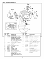
Repair
Rail assembly parts ...........................
37
Install the light ...............................
18
Installation parts ..............................
37
Attach the emergency release rope and handle .....
18
Motor unit assembly parts ......................
38
Electrical requirements .........................
19
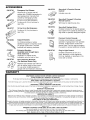
Accessories
39
39
Install The Protector System <_
.................
20-22
Fasten the door bracket .....................
23-24
Warranty
Connect the door arm to the trolley ............
25-26
Repair
Parts
Parts
37-38
and
Service
Backcover
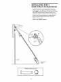
INTRODUCTION
Safety
Symbol
and Signal
Word
Review
This garage door opener has been designed and tested to offer safe service provided it is installed, operated,
maintained and tested in strict accordance with the instructions and warnings contained in this manual.
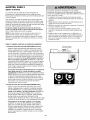
Mechanical
When you see these Safety Symbols and Signal Words on
the following pages, they will alert you to the possibility of
serious injury or death if you do not comply with the
warnings that accompany them, The hazard may come
from something mechanical or from electric shock. Read
the warnings carefully.
Electrical
When you see this Signal Word on the following pages, it
will alert you to the possibility of damage to your garage
door and/or the garage door opener if you do not comply
with the cautionary statements that accompany it. Read
them carefully.
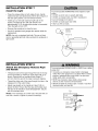
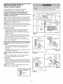
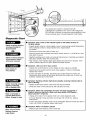
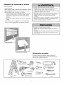
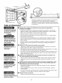
Preparing
your
garage
door
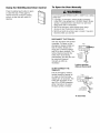
Before you begin:
• Disable locks.
To prevent possible SERIOUSINJURYor DEATH:
• ALWAYScall a trained door systems technician if garage
door binds, sticks, or is out of balance. An unbalanced
garage door may NOT reverse when required.
• Remove any ropes connected to garage door.
• Complete the following test to make sure your garage
door is balanced and is not sticking or binding:
• NEVERtry to loosen, move or adjust garage door, door
springs, cables, pulleys, brackets or their hardware, all of
which are under EXTREMEtension.
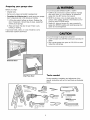
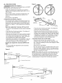
1. Lift the door about halfway as shown. Release the
door. If balanced, it should stay in place, supported
entirely by its springs.
• Disable ALL locks and remove ALL ropes connected to
garage door BEFOREinstalling and operating garage door
opener to avoid entanglement.
2. Raise and lower the door to see if there is any
binding or sticking.
If your door binds, sticks, or is out of balance, call a
trained door systems technician.
To prevent damageto garage door and opener:
• ALWAYSdisable locks BEFOREinstalling and operating the
opener.
• ONLY operate garage door opener at 120V, 60 Hz to avoid
malfunction and damage.
Sectional Door
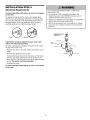
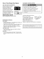
Tools
One-Piece Door
needed
During assembly, installation and adjustment of the
opener, instructions will call for hand tools as illustrated
below.
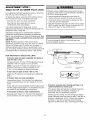
Pencil
Level (optional)
Hack Saw
Tape Measure
Claw Hammer
Drill
Wire Cutters
Drill Bits
3/16", 5/16"
00
Stepladder
and 5/32"
Screwdriver
o3
End Wrench
UU A
1/2", 5/8", 7/16", 9/16"
and 1/4"
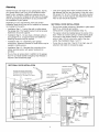
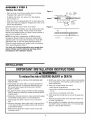
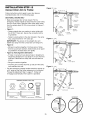
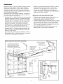
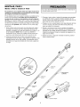
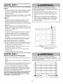
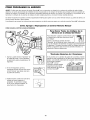
Planning
Look at the garage door where it meets the floor. Any
gap between the floor and the bottom of the door must
not exceed 1/4" (6 mm). Otherwise, the safety reversal
system may not work properly. See Adjustment Step 3.
Floor or door should be repaired.
Identify the type and height of your garage door. Survey
your garage area to see if any of the conditions below
apply to your installation. Additional materials may be
required. You may find it helpful to refer back to this page
and the accompanying illustrations as you proceed with
the installation of your opener.
Depending on your requirements, there are several
installation steps which may call for materials or hardware
not included in the carton.
SECTIONAL DOOR INSTALLATIONS
• Do you have a steel, aluminum, fiberglass or glass panel
door? If so, horizontal and vertical
reinforcement is required (Installation Step 11).
• Installation Step 1 - Look at the wall or ceiling above
the garage door. The header bracket must be securely
fastened to structural supports.
• The opener should be installed above the center of the
door. If there is a torsion spring or center bearing plate
in the way of the header bracket, it may be installed
within 4 feet (1.22 m) to the left or right of the door
center. See Installation Steps 1 and 11.
• Installation Step 5 - Do you have a finished ceiling in
your garage? If so, a support bracket and additional
fastening hardware may be required.
• Installation Step 10 - Depending upon garage
construction, extension brackets or wood blocks may be
needed to install sensors.
• If your door is more than 7 feet (2.13 m) high, see rail
extension kits listed on Accessories page.
• Installation Step 10 -Alternate floor mounting of the
safety reversing sensor will require hardware not
provided.
• Do you have an access door in addition to the garage
door? If not, Model 53702 Emergency Key Release is
required. See Accessories page.
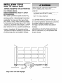
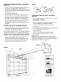
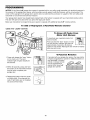
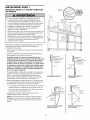
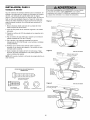
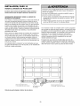
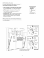
SECTIONAL DOOR INSTALLATION
FINISHED
Horizontal and vertical reinforcement
is needed for lightweight garage doors
(fiberglass, steel, aluminum, door with
glass panels, etc.). See page 23 for details.
CEILING
Supf
fastening hardware
is required.
See page 16.
Slack in chain tension
is normal when
garage door is closed.
Header Wall
Extension
OR
Torsion Spring
Motor unit
Spring
U
I
Wallmounted
Door
Control
Centerline_l
Header
Bracket
/
CLOSED
POSITION
Trolley
Stop Bolt Trolley
O
Chain
Gap between floor
and bottom of door
Safety Reversing Sensor
Emergency
Release
Rope &
Handle
Safety Reversing
Sensor
must not exceed 1/4" (6 mm).
Door Arm
Door
Bracket
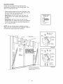
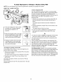
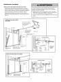
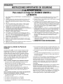
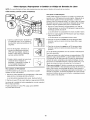
Planning
(Continued)
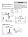
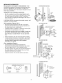
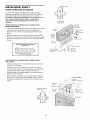
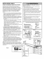
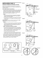
ONE-PIECE DOOR INSTALLATIONS
• Generally, a one-piece door does not require
reinforcement If your door is lightweight, refer to the
information relating to sectional doors in Installation
Step 11
• Depending on your door's construction, you may need
additional mounting hardware for the door bracket
(Step 11)
Without a properly working safety reversal system, persons
(particularly small children) could be SERIOUSLYINJUREDor
KILLED by a closing garage door.
• The gap between the bottom of the garage door and the floor
MUST NOTexceed 1/4" (6 mm). Otherwise, the safety
reversal system may NOTwork properly.
• The floor or the garage door MUST be repaired to eliminate
the gap.
ONE-PIECE DOOR WITHOUT TRACK
FINISHED CEILING
Support bracket
& fastening
hardware is required.
See page 16.
Rail
Header Wall
Slack in chain tension
is normal when garage
door is closed.
Motor Unit
Wall-mounted
Door Control
J
Access
Door
CLOSED
Trolley Stop Bolt
I
POSITION
Cable
Trolley
O
Bracket
Rail
Door Bracket
Safety Reversing
Sensor
Gap between floor
and bottom of door must not exceed 1/4" (6 mm).
light
Door
Arm
Safety Reversing Sensor
leader
Vail
--
Emergency
Release
Rope & Handle
Curved
Door
Arm
Garage Door
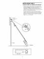
ONE-PIECE DOOR WITH TRACK
CLOSED
Trolley
Stop Bolt
k
\
Safety Reversing
J
Safety Reversing
Sensor
Cable
Trolley
Chain
/
L
Header
.
Bracket
Rail
_XIDoor
Gap between floor and bottom of door
must not exceed 1/4" (6 mm).
POSITION
ooooooooooo)
/
Straight
Y//ABracket
DoorArm
_///J_ Garage
Y//I Door
_ I
/
/
C_
_
CUrv'ed
_,___v_,
_ Emergency
I Release
I RODe &
u°°r_'m
_L
I
Handle
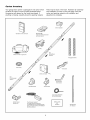
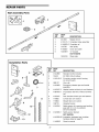
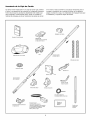
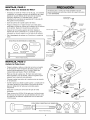
Carton
Inventory
Your garage door opener is packaged in one carton which
contains the motor unit and all parts illustrated below.
Accessories will depend on the model purchased. If
anything is missing, carefully check the packing material.
Parts may be stuck in the foam. Hardware for assembly
and installation is shown on the next page. Save the
carton and packing material until installation and
adjustment is complete.
Chain Spreader
SECURITY+ ®
3-Function Remote Control
Standard Control Console
with visor clip (2)
,P
€1
oP
Trolley
Rail
Center/Back
Sections
Motor Unit with a Light Lens
Hanging Brackets
@
Idler Pulley
Chain and Cable
Rail
Front (header)
Section
Curved Door
Arm Section
Header Bracket
Door Bracket
2-Conductor Bell Wire
White & White/Red
Safety Sensor
Bracket (2)
The Protector System ®
(2) Safety Reversing Sensors
(1 Sending Eye and 1 Receiving Eye)
with 2-Conductor White & White/Black
Bell Wire attached
Safety Labels
and
Literature
Straight Door
Arm Section
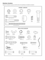
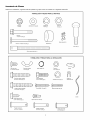
Hardware
Inventory
Separate all hardware and group as shown below for the assembly and installation procedures.
ASSEMBLY HARDWARE
Lock Nut
1/4"-20 (2)
Washer
Bolt 1/4"-20xl-3/4"
5/8" (2)
Lock Washer
3/8" (1)
Nut
3/8" (1)
1
(2)
Bolt 1/4"-20x2-1/2
(1)
i
i
Master
Link (2)
Spacer (2)
Idler Bolt (1)
Trolley Threaded
Shaft (1)
INSTALLATION
HARDWARE
0
Carriage Bolt
1/4"-20xl/2"
(2)
Wing Nut
1/4"-20 (2)
Ring
Fastener (3)
Handle
Nut 5/16"-18 (6)
_,1111111111
D
Lag Screw
5/16"-9xl-5/8"
(2)
111111111111_>
Lag Screw
5/16"-18xl -7/8" (2)
_ng
Hex Bolt
5/16"- 18x7/8" (4)
Lock Washer
_ IMIMlllllllllllMlllIlllll_
Screw
6ABx 1- 1/4" (2)
5/16" (5)
Insulated
Staples (30)
] IIIIIIIIIIIIIIIIIIIII
Screw 6-32xl"
(2)
Rope
Screw
1/4"-14x5/8"
Drywall Anchors (2)
(2)
o]
Clevis Pin
5/16"x1-1/2"
(1)
oD
Clevis Pin
5/16"x1" (1)
oV
Clevis Pin
5/16"x1-1/4"
(1)
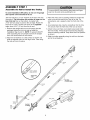
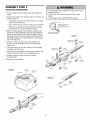
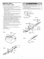
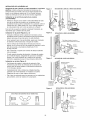
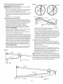
ASSEMBLY
Assemble
STEP
the Rail
1
& Install
the
Trolley
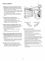
To prevent INJURYfrom pinching, keep hands and fingers
away from the joints while assembling the rail.
To avoid installation difficulties, do not run the garage
door opener until instructed to do so.
The front rail has a cut out "window" at the door end (see
illustration). The hole above this window is larger on the
top of the rail than on the bottom. A smaller hole
3-1/2" (8.9 cm) away is close to the rail edge. Rotate the
back rail so # has a similar hole close to the opposite
edge, about 4-3/4" (12 cm) from the far end.
3. Place the motor unit on packing material to protect the
cover, and rest the back end of the rail on top. For
convenience, put a support under the front end of the
rail.
1. Remove the straight door arm and hanging bracket
packaged inside the front rail and set aside for
Installation Step 5 and 12. NOTE: To prevent INJURY
while unpacking the rail carefully remove the straight
door arm stored within the rail section.
5. Check to be sure there are 4 plastic wear pads inside
the inner trolley. If they became loose during shipping,
check all packing material. Snap them back into position
as shown.
2. Align the rail sections on a flat surface as shown and
slide the tapered ends into the larger ones. Tabs along
the side will lock into place.
4. As a temporary stop, insert a screwdriver into the hole
10" (25 cm) from the front end of the rail, as shown.
6. Slide the trolley assembly along the rail from the back
end to the screwdriver.
Trolley
)ered
End
)ered
End
Back Rails
(TO MOTOR UNIT)
3ered
End
)ered
End
_._rewd
"_"
Window 0
////
Cut-Out ', ///
\
.,L_//
Idler _/".._.,J/
Pulley
H01e
///
Inner Trolley
rive_
Tabs
Front Rail
(TO DOOR)
_ar
Pads
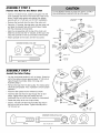
ASSEMBLY
Fasten
the
STEP
Rail
2
to the
Motor
Unit
To avoid SERIOUSdamage to garage door opener, use ONLY
those bolts/fasteners mounted in the top of the opener.
• Insert a 1/4"-20x2-1/2 bolt, washer and spacer into the
cover protection bolt hole on the back end of the rail as
shown. Install lower spacer and washer then tighten
securely with a 1/4"-20 lock nut. DO NOT overtighten.
• Remove the two bolts from the top of the motor unit.
• Place the "U" bracket, flat side down onto the motor unit
and align the bracket hole with the bolt holes. Fasten
with the previously removed bolts.
Bolt
1/4"-20x2-1/2
• Align the rail assembly with the top of the motor unit.
Slide the rail end onto the "U" bracket, all the way to the
stops that protrude on the top and sides of the brackeL
I
• Attach spreader to the motor unit with two screws.
HARDWARE
SHOWN
ACTUAL
Motor Unit
Sprocket
"U" Bracket
Washer 5/8"
SIZE
Spacer.,x_
Cover
Protection
Bolt Hole
Q
Washer 5/8"
Chain
Spreader
Bolt
Lock Nut 1/4"-20
Spacer_Washer
Spacer
i
5/8"
Lock Nut
1/4"-20
B01t 1/4"-20x2-1/2"
ASSEMBLY
Install
the
STEP
Idler
Bolt
Chain and
Cable
3
Pulley
P_ai
• Lay the chain/cable beside the rail, as shown. Grasp the
end of the cable and pass approximately 12" (30 cm) of
cable through the window. Allow it to hang until
Assembly Step 5.
Washer
Idler_
Bolt
• Remove the tape from the idler pulley. The inside center
should be pre-greased. If dry, regrease to ensure proper
operation.
Trolley
_
Screwdriver
i
i
i
i
i
Bolt
• Place the idler pulley into the window as shown.
Trolley
Stop Hole
• Insert the idler bolt from the top through the rail and
pulley. Tighten with a 3/8" lock washer and nut
underneath the rail until the lock washer is compressed.
_
-.._lnside
Lock
Washer
3/8"
• Rotate the pulley to be sure it spins freely.
• Insert a 1/4"-20xl-3/4 bolt into the trolley stop hole in
the front of the rail as shown. Tighten securely with a
1/4"-20 lock nut.
HARDWARE
Idler Bolt
t
Grease
Pulley
_
Idler
Pulley
--_
i
I_--
,
Nut 3/8"
Cable Link
SHOWN ACTUAL
Bolt 1/4"-20x1-3/4
SIZE
Lock Nut 1/4"-20
Nut 3/8"
Lock Washer 3/8"
ASSEMBLY
Install
the
STEP
4
Chain/Cable
To avoid possible SERIOUSINJURYto fingers from moving
garage door opener:
• ALWAYS keep hand clear of sprocket while operating
opener.
• Securely attach chain spreader BEFOREoperating.
1. Pull the cable around the idler pulley and toward the
trolley.
2. Connect the cable to the retaining slot on the trolley, as
shown (Figure 1):
• From below, push pins of master link bar up through
cable link and trolley slot.
Dispensing
Carton
Leave Chain and Cable
Inside Dispensing
Carton to Prevent Kinking.
• Push master link cap over pins and past pin notches.
• Slide clip-on spring over cap and onto pin notches
until both pins are securely locked in place.
3. With the trolley against the screwdriver, dispense the
remainder of the cable/chain along the rail toward the
motor unit into the slot on the chain spreader, around
the sprocket onto the chain spreader and continuing to
the trolley assembly. The sprocket teeth must engage
the chain (Figure 2).
Keep Chain and Cable
Taut When Dispensing
Figure 1
::
Master Link ._
4. Check to make sure the chain is not twisted, then
connect it to the threaded shaft with the remaining
master link.
Master
Link Cap
Clip-On Spring
5. Thread the inner nut and lock washer onto the trolley
threaded shaft (Figure 3).
Master Link
Master
Clip-On Spring
Link Cap
_
6. Insert the trolley threaded shaft through the hole in the
trolley. Be sure the chain is not twisted (Figure 4).
i
i
7. Loosely thread the outer nut onto the trolley
threaded shaft.
8. Remove the screwdriver.
Trolley
Threaded
Cable
Link
Idler
Shaft
Round
Hole
Pulley
Slotted
Hole
Cable
Figure 2
Chain
Spreader
t_)-_
Master
Link Bar
Motor Unit
Sprocket
Figure 3
Trolley
Threaded
Shaft
Inner Nut
5/16"
Figure 4
Trolley
Threaded
Shaft
Round
Hole
10
i
:
_
Pin
Notch
Master
Link Bar
ASSEMBLY
Tighten
the
STEP
5
Chain
Figure 1
• Spin the inner nut and lock washer down the trolley
threaded shaft, away from the trolley.
Outer Lock
Nut
Washer
Trolley
Threaded
Shaft
To Tighten Outer Nut
• To tighten the chain, turn outer nut in the direction
shown (Figure 1).
Inner Nut
• When the chain is approximately 1/4" (6 mm) above the
base of the rail at its midpoint, re-tighten the inner nut to
secure the adjustment.
To Tighten
Inner Nut
Sprocket noise can result if chain is too loose.
Figure 2
I
When installation is complete, you may notice some chain
droop with the door closed. This is normal. If the chain
returns to the position shown in Figure 2 when the door is
open, do not re-adjust the chain.
Chain
1/4" (6 mm)
NOTE: During future maintenance, ALWAYS pull the
emergency release handle to disconnect trolley before
adjusting chain. You may notice loosening of chain after
Adjustment Step 3 (Test the Safety Reversal System).
Check for proper tension and readjust chain if necessary.
Then repeat Adjustment Step 3.
Rail
Mid length of Rail
You have now finished assembling your garage door
opener. Please read the following warnings before
proceeding to the installation section.
INSTALLATION
IMPORTANTINSTALLATIONINSTRUCTIONS
To reducethe riskofSEVEREINJURYor DEATH:
1. READAND FOLLOWALL INSTALLATIONWARNINGSAND
INSTRUCTIONS.
2. Install garage door opener ONLYon properly balanced and
lubricated garage door. An improperly balanceddoor may
NOT reverse when required and could result in SEVERE
INJURYor DEATH.
3. ALL repairs to cables, spring assemblies and other hardware
MUST be made by a trained door systems technician BEFORE
installing opener.
4. DisableALL locks and remove ALL ropes connected to garage
door BEFOREinstalling opener to avoid entanglement.
5. Install garage door opener 7 feet (2.13 m) or more above
floor.
6. Mount the emergency releasewithin reach, but at least 6 feet
(1.8 m) above the floor and avoiding contact with vehicles to
avoid accidental release.
7. NEVERconnect garage door opener to power source until
instructed to do so.
11
8. NEVERwear watches, rings or loose clothing while installing
or servicing opener. They could be caught in garage door or
opener mechanisms.
9. Install wall-mounted garage door control:
• within sight of the garage door.
• out of reach of children at minimum height of 5 feet
(1.5 m).
• away from ALL moving parts of the door.
10. Placeentrapment warning label on wall next to garage door
control.
11. Placemanual release/safetyreverse test label in plain view
on inside of garage door.
12. Upon completion of installation, test safety reversal system.
Door MUST reverse on contact with a 1-1/2" (3.8 cm) high
object (or a 2x4 laid flat) on the floor.
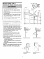
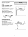
INSTALLATION
Determine
the
STEP
Header
Unfinished
Ceiling
1
Bracket
OPTIONAL
CEILING
MOUNT
FOR
HEADER
BRACKET
Location
HeaderWall
To prevent possible SERIOUSINJURYor DEATH:
• Header bracket MUST be RIGIDLYfastened to structural
support on header wall or ceiling, otherwise garage door
might NOT reverse when required. DONOT install header
bracket over drywall.
• Concrete anchors MUST be used if mounting header bracket
or 2x4 into masonry.
• NEVERtry to loosen, move or adjust garage door, springs,
cables, pulleys, brackets, or their hardware, ALL of which
are under EXTREMEtension.
Vertical Centerline
of Garage Door
2x4
Structural
Supports
• ALWAYScall a trained door systems technician if garage
door binds, sticks, or is out of balance. An unbalanced
garage door might NOT reverse when required.
Installation procedures vary according to garage door
types. Follow the instructions which apply to your door.
1. Close the door and mark the inside vertical centerline of
the garage door.
2. Extend the line onto the header wall above the door.
You can fasten the header bracket within 4 feet
(1.22 m) of the left or right of the door center only if
a torsion spring or center bearing plate is in the
way; or you can attach it to the ceiling (see page 13)
when clearance is minimal. (It may be mounted on
the wall upside down if necessary, to gain
approximately
1/2" (1 cm).
Header Wall
HeaderWall
Highest Point
of Travel
If you need to install the header bracket on a 2x4
(on wall or ceiling), use lag screws (not provided)
to securely fasten the 2x4 to structural supports as
shown here and on page 13.
Y
--Door
3. Open your door to the highest point of travel as shown.
Draw an intersecting horizontal line on the header wall
above the high point:
Track
Tlaok
15'--" Clll)
Sectional door with curvedtrack
Hfighest Point
Travel
T
One-piece door with horizontal track
• 2" (5 cm) above the high point for sectional door and
one-piece door with track.
• 8" (20 cm) above the high point for one-piece door
without track.
This height will provide travel clearance for the top edge
of the door.
Header Wall
:- 8" (20 cm)
_---_:= =----_,
I_ Heal,_._Wall
ooor 2° ihest
NOTE: If the total number of inches exceeds the height
available in your garage, use the maximum height
possible, or refer to page 13 for ceiling installation.
I_
Point
', Highest
,, Point
" of Travel
Door
Pivot
€__Hard_are
I
of Travel
One-piece door without track:
jamb hardware
12
One-piece door without track:
pivot hardware
INSTALLATION
STEP
Install
Bracket
the
Header
2
Wall Mount
You can attach the header bracket either to the wall above
the garage door, or to the ceiling. Follow the instructions
which will work best for your particular requirements. Do
not install the header bracket over drywall. If installing
into masonry, use concrete anchors (not provided).
WALL HEADER BRACKET INSTALLATION
Optional
Mounting
• Center the bracket on the vertical centerline with the
bottom edge of the bracket on the horizontal line as
shown (with the arrow pointing toward the ceiling).
• Mark the vertical set of bracket holes. Drill 3/16" pilot
holes and fasten the bracket securely to a structural
support with the hardware provided.
Holes
Vertical
Centerline
of Garage Door
- Header Wall -
2x4
Structural
Support
Lag Screws
5/16"-9xl -5/8"
pring
J
HARDWARE
SHOWN ACTUAL
t
SIZE
Horizontal
Line
/
/"
- Garage Door--
Highest Point of
Garage Door Travel
5/16"-9xl
CEILING HEADER BRACKET
-5/8"
Vertical
Centerline
of Garage Door
INSTALLATION
• Extend the vertical centerline onto the ceiling as shown.
• Center the bracket on the vertical mark, no more than
6" (15 cm) from the wall. Make sure the arrow is
pointing away from the wall. The bracket can be
mounted flush against the ceiling when clearance
is minimal.
- Finished Ceiling -
• Mark the side holes. Drill 3/16" pilot holes and fasten
bracket securely to a structural support with the
hardware provided.
Vertical Centerline
of Garage Door
Bracket _.
6" (15 cm) Ma_.um
Door
Spring
Ceiling Mounting Holes
Lag Screws
5/16"-9xl -5/8"
-
13
Header Wall -
INSTALLATION
Attach
the
STEP
Rail
to the
3
Header
Bracket
• Position the opener on the garage floor below the
header bracket. Use packing material as a protective
base. NOTE: If the door spring is in the way you'll need
help. Have someone hold the opener securely on a
temporary support to allow the rail to clear the spring.
• Position the rail bracket against the header bracket.
• Align the bracket holes and join with a clevis pin
5/16"xl -1/2" as shown.
• Insert a ring fastener to secure.
--
Idler Pulley
0
Header
i
Mounting
Hole
Door
Opener Carton or
Support
HARDWARE
SHOWN
ACTUAL
SIZE
©
Clevis Pin 5/16"x1-1/2"
Ring Fastener
14
INSTALLATION
Position
the
STEP
4
Opener
To prevent damageto garage door, rest garage door opener
rail on 2x4 placed on top section of door.
Follow instructions which apply to your door type as
illustrated.
SECTIONAL
TRACK
DOOR OR ONE-PIECE DOOR WITH
A 2x4 laid flat is convenient for setting an ideal
door-to-rail distance.
Rail
• Remove foam packaging.
• Raise the opener onto a stepladder. You will need help
at this point if the ladder is not tall enough.
• Open the door all the way and place a 2x4 laid flat on
the top section beneath the rail.
2x4 is used to determine
the correct mounting height
from ceiling.
Door
• If the top section or panel hits the trolley when you raise
the door, pull down on the trolley release arm to
disconnect inner and outer sections. Slide the outer
trolley toward the motor unit. The trolley can remain
disconnected until Installation Step 12 is completed.
olley _,_
ENGAGED
leaseArm
--t
RELEASED
I
ONE-PIECE DOOR WITHOUT TRACK
A 2x4 on its side is convenient for setting an ideal
door-to-rail distance.
• Remove foam packaging.
Header
• Raise the opener onto a stepladder. You will need help
at this point if the ladder is not tall enough.
• Open the door all the way and place a 2x4 on its side
on the top section of the door beneath the rail.
I
• The top of the door should be level with the top of the
motor unit. Do not position the opener more than
4" (10 cm) above this point.
i
15
2x4 is used to determine
the correct mounting height
from ceiling.
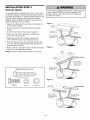
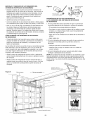
INSTALLATION
Hang
the
STEP
5
Opener
To avoid possible SERIOUSINJURYfrom a falling garage door
opener, fasten it SECURELYto structural supports of the
garage. Concrete anchors MUST be used if installing any
brackets into masonry.
Three representative installations are shown. Yours may
be different. Hanging brackets should be angled (Figure 1)
to provide rigid support. On finished ceilings (Figure 2 and
Figure 3), attach a sturdy metal bracket to structural
supports before installing the opener. This bracket and
fastening hardware are not provided.
1. Measure the distance from each side of the motor unit
to the structural support.
Figure 1
Structural
Supports
2. Cut both pieces of the hanging bracket to required
lengths.
./C
Lag Screws
5/1 6"-1 8xl -7/8"
3. Drill 3/16" pilot holes in the structural supports.
_-Bolt 5/16"-18x7/8"
Lock Washer 5/16"
Nut 5/16"-18
4. Attach one end of each bracket to a support with
5/16"-18xl -7/8" lag screws.
5. Fasten the opener to the hanging brackets with
5/16"-18x7/8" hex bolts, lock washers and nuts.
6. Check to make sure the rail is centered over the door
(or in line with the header bracket if the bracket is not
centered above the door).
Distance
Figure 2
7. Remove the 2x4. Operate the door manually. If the door
hits the rail, raise the header bracket.
NOTE: DO NOT connect power to opener at this time.
Hidden
Support
.........
Bracket
Lag Screws
I.....
_
8/16"-18xl-7/8"
- - -___
_FINISH ED CEILIN G
----'_--__//_
(Not Provided)
T_-_- -_._1/o_,_"-_%_,_------z-----_-_IZ/--
HARDWARE
_l
SHOWN
Bolt 5/16"-18x7/8"
Lock Washer 5/16"
_\
_
Nut 8/16"-18
LBoo;tk5/W16
';-h18X7(8",, _
,_._Jo/_
ACTUAL SIZE
Lla!Ic!elw[ll!,,_ll!xll_718
. I
I
Nut 8/16"-18
I
P,,,,,,,,,,D
@
Hex B01t
5/16"-18x7/8"
- -/t_7 ....
_-
Nut 5/16"-18
5_
Figure 3
Lock Washer 5/16"
|_rl£pr_\_/q5/1_6,7.18_Xi...7/8
'' --_L._L__LLL2L
(Not Provided)
Bolt 5/16"-18x7/8"
8 6"
16
_1_
x
_
D CEILING
/_P'/
/_1
Bolt 5/16"-18x7/8"
Lock Washer 5/16"
INSTALLATION
Install
the
Door
STEP
6
Control
To prevent possible SERIOUSINJURYor DEATHfrom
electrocution:
Locate door control within sight of door, at a minimum
height of 5 feet (1.5 m) where small children cannot reach,
away from moving parts of door and door hardware.
If installing into drywall, drill 5/32" holes and use the
anchors provided. For pre-wired installations (as in new
home construction), it may be mounted to a single gang
box (Figure 1).
• Be sure power is NOT connected BEFOREinstalling door
control.
• Connect ONLYto 24 VOLT low voltage wires.
To prevent possible SERIOUSINJURYor DEATHfrom a closing
garage door:
• Install door control within sight of garage door, out of reach
of children at a minimum height of 5 feet (1.5 m), and away
from ALL moving parts of door.
• NEVERpermit children to operate or play with door control
push buttons or remote control transmitters.
• Activate door ONLYwhen it can be seen clearly, is properly
adjusted, and there are no obstructions to door travel.
• ALWAYSkeep garage door in sight until completely closed.
NEVERpermit anyoneto cross path of closing garage door.
1. Strip 7/16" (11 mm) of insulation from one end of bell
wire and connect to the two screw terminals on back of
door control by color: white wire to 2 and white/red wire
to the 1 (Figure 2).
2. Remove cover by gently prying along one side with a
screwdriver (Figure 3). Fasten with 6ABx1-1/4"
self-tapping screws (drywall installation) or 6-32x1"
machine screws (into gang box) as follows:
• Install bottom screw, allowing 1/8" (3 mm) to protrude
above wall surface.
HARDWARE
• Position bottom of door control on screw head and
slide down to secure. Adjust screw for snug fit.
SHOWN ACTUAL
SIZE
''']>
• Drill and install top screw with care to avoid cracking
plastic housing. DO NOT overtighten.
Insulated
Staples
Control Console (std installation)
• Insert top tabs and snap on cover.
3. (For standard installation only) Run bell wire up wall
and across ceiling to motor unit. Use insulated staples to
secure wire in several places. DO NOT pierce wire with
a staple, creating a short or open circuit.
Control Console (pre-wired)
Drywall Anchors
Figure 1
4. Strip 7/16" (11 mm) of insulation from end of bell wire.
Connect bell wire to the quick-connect terminals as
follows: white to white and white/red to red (Figure 4).
Figure 2
PRE-WIRED
INSTALLATION
(BACK VIEW)
NOTE: When connecting multiple door controls to the
opener, twist same color wires together. Insert wires into
quick-connect holes: white to white and red/white to red.
5. Position the antenna wire as shown.
To release or insert wire,
)ush in tab with screwdriver
Hole
Terminal
111
24 Volt
2-Conductor
Bell Wire
Ill
_
Bell I[ =
Wire "_"
_
Mounting
IIscrews
II Bottom
Mounting
Hole
Figure 3
REMOVE &
REPLACE COVER
Insert Top Tabs /
First
.
./ t
To Replace,
tip
Strip wire 7/16" (11 mm)
(7/161'
L_-I'_I_
._I
NOTE: DO NOT connect power and operate opener at
this time. The trolley will travel to the full open position but
will not return to the close position until the sensor beam is
connected and properly aligned.
Door Control
Connections
Top
II _
6. Use tacks or staples to permanently attach entrapment
warning label to wall near door control, and manual
release/safety reverse test label in a prominent location
on inside of garage door.
Figure 4
I'#qT/ l
{11 mm)_*
_
-Conductor
Red White Grey
Bell Wire
Lighted
Push Button
STANDARD
CONTROL CONSOLE
17
I
Twist Here
To_emove,
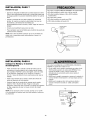
INSTALLATION
Install
the
STEP
7
Light
To prevent possible OVERHEATINGof the endpanel or light
socket,
• DO NOT use short neck or specialty light bulbs.
• DO NOT use halogen bulbs. Use ONLY incandescent.
To prevent damageto the opener:
• DO NOT use bulbs larger than IOOW.
• ONLY use A19 size bulbs.
• Press the release tabs on both sides of lens. Gently
rotate lens back and downward until the lens hinge is in
the fully open position. Do not remove the lens.
• Install up to a 100 watt maximum light bulb in the
socket. The light will turn ON and remain lit for
approximately 4-1/2 minutes when power is connected.
Then the light will turn OFF.
• Reverse the procedure to close the lens.
• Use A19, standard neck garage door opener bulbs for
replacement.
Standard
Light Bulb
00 Watt (Max)
(__
NOTE: Use only a standard light bulb. The use of short
neck or speciafity light bulb may overheat the endpanel or
light socket.
Release Tab
\
_Leng
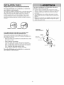
INSTALLATION
Attach
the
and Handle
STEP
Emergency
e
/)/
8
Release
Rope
To prevent possible SERIOUSINJURYor DEATHfrom a falling
garage door:
• If possible, use emergency releasehandle to disengage
trolley ONLYwhen garage door is CLOSED.Weak or broken
springs or unbalanceddoor could result in an open door
falling rapidly and/or unexpectedly.
• NEVERuse emergency releasehandle unless garage
doorway is clear of persons and obstructions.
• NEVERuse handle to pull door open or closed. If rope knot
becomes untied, you could fall.
• Thread one end of the rope through the hole in the top
of the red handle so "NOTICE" reads right side up as
shown. Secure with an overhand knot at least 1"
(2.5 cm) from the end of the rope to prevent slipping.
• Thread the other end of the rope through the hole in the
release arm of the outer trolley.
• Adjust rope length so the handle is 6 feet (1.83 m)
above the floor. Ensure that the rope and handle clear
the tops of all vehicles to avoid entanglement. Secure
with an overhand knot.
Trolley
•
NOTE: If it is necessary to cut the rope, heat seal the cut
end with a match or lighter to prevent unraveling.
I
I
__e
ar_m_ _
Emergency
Release Handle
18
_
Overhand
_
Knot
INSTALLATION
Electrical
STEP
9
Requirements
To prevent possible SERIOUSINJURYor DEATHfrom
electrocution or fire:
To avoid installation difficulties, do not run the opener
at this time.
• Be sure power is NOT connected to the opener, and
disconnect power to circuit BEFOREremoving cover to
establish permanent wiring connection.
• Garage door installation and wiring MUST be in compliance
with all local electrical and building codes.
• NEVERuse an extension cord, 2-wire adapter, or change
plug in any way to make it fit outlet. Be sure the opener is
grounded.
To reduce the risk of electric shock, your garage door
opener has a grounding type plug with a third grounding
pin. This plug will only fit into a grounding type outlet. If
the plug doesn't fit into the outlet you have, contact a
qualified electrician to install the proper outlet.
PERMANENT
CONNECTION
RIGH_
WIRING
WRONG
Ground Tab
If permanent wiring is required by your local code,
refer to the following procedure.
Green
Ground Screw
To make a permanent connection through the 7/8" hole in
the top of the motor unit:
• Remove the motor unit cover screws and set the cover
aside.
Ground Wire
• Remove the attached 3-prong cord.
White Wire
• Connect the black (line) wire to the screw on the brass
terminal; the white (neutral) wire to the screw on the
silver terminal; and the ground wire to the green ground
screw. The opener must be grounded.
• Reinstall the cover.
To avoid installation
at this time.
difficulties,
do not run the opener
19
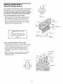
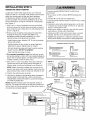
INSTALLATION
Install
The
Protector
STEP
10
System
®
Be sure power is NOTconnected to the garage door opener
BEFOREinstalling the safety reversing sensor.
To prevent SERIOUSINJURY or DEATHfrom a closing
garage door:
• Correctly connect and align the safety reversing sensor. This
required safety device MUST NOT be disabled.
• Install the safety reversing sensor so beam is NO HIGHER
than 6" (15 cm) above garage floor.
The safety reversing sensor must be connected and
aligned correctly before the garage door opener will
move in the down direction.
IMPORTANT INFORMATION ABOUT THE SAFETY
REVERSING SENSOR
When properly connected and aligned, the sensor will
detect an obstacle in the path of its electronic beam. The
sending eye (with an amber indicator light) transmits an
invisible light beam to the receiving eye (with a green
indicator light). If an obstruction breaks the light beam
while the door is closing, the door will stop and reverse to
full open position, and the opener lights will flash 10 times.
If it is necessary to mount the units on the wall, the
brackets must be securely fastened to a solid surface such
as the wall framing. Extension brackets (see accessories)
are available if needed. If installing in masonry
construction, add a piece of wood at each location to
avoid drilling extra holes in masonry if repositioning is
necessary.
The units must be installed inside the garage so that the
sending and receiving eyes face each other across the
door, no more than 6" (15 cm) above the floor. Either can
be installed on the left or right of the door as long as the
sun never shines directly into the receiving eye lens.
The invisible light beam path must be unobstructed. No
part of the garage door (or door tracks, springs, hinges,
rollers or other hardware) may interrupt the beam while
the door is closing.
The mounting brackets are designed to clip onto the track
of sectional garage doors without additional hardware.
]0I
]0l
]÷I
]I
Safety Reversing
Sensor
Safety Reversing
Invisible Light Beam
Protection Area
Facing the door from inside the garage
20
Sensor
INSTALLING THE BRACKETS
Be sure power to the opener is disconnected. Install
and align the brackets so the sensors will face each other
across the garage door, with the beam no higher than
6" (15 cm) above the floor. They may be installed in one of
three ways, as follows.
Garage door track installation
DOORTRACK MOUNT (RIGHT SIDE)
:,ip IitI
(preferred):
• Slip the curved arms over the rounded edge of each
door track, with the curved arms facing the door. Snap
into place against the side of the track. It should lie
flush, with the lip hugging the back edge of the track, as
shown in Figure 1.
. Reversing "l"ll_r_
_--_.,'_z'b_
Sensor
If your door track will not support the bracket securely, wall
installation is recommended.
Wall installation
,, dicator
"_
(Figures 2 & 3):
Bracket
III ) L._
WALL MOUNT (RIGHT SIDE)
• Place the bracket against the wall with curved arms
facing the door. Be sure there is enough clearance for
the sensor beam to be unobstructed.
FastenWood Blockto Wallwith
I Screws(not provided)
• If additional depth is needed, an extension bracket (See
Accessories) or wood blocks can be used.
Indicator
Light
• Use bracket mounting holes as a template to locate and
drill (2) 3/16" diameter pilot holes on the wall at each
side of the door, no higher than 6" (15 cm) above the
floor.
_
Lag Screws
(not provided)
Lens ......
• Attach brackets to wall with lag screws (Not provided).
• If using extension brackets or wood blocks, adjust right
and left assemblies to the same distance out from the
mounting surface. Make sure all door hardware
obstructions are cleared.
Floor installation
Safety
Reversing
Sensor
Bracket
WALL MOUNT (RIGHT SIDE)
Extension r c
(Figure 4):
SeesorioS,Provided
with
• Use wood blocks or extension brackets (See
Accessories) to elevate sensor brackets so the lenses
will be no higher than 6" (15 cm) above the floor.
l-_J__
• Carefully measure and place right and left assemblies at
the same distance out from the wall. Be sure all door
hardware obstructions are cleared.
racket)
• Fasten to the floor with concrete anchors as shown.
._. ___
?_" _
(Providedwith
ExtensionBracket)---_""
Safety
Reversing
__
X
Sensor
\
Bracket
Indicator
&'%"-,..-J I
Lens
Light
FLOORMOUNT (RIGHT SIDE)
HARDWARE
SHOWN
ACTUAL
SIZE
-;
Carriage Bolt
1/4"-20xl/2"
Wing Nut
1/4"-20
Staples
ttach with
Concrete Anchors
(not provided)
Indicator
Light
J
21
Safe_
Reversing
Sensor
Bracket
MOUNTING AND WIRING THE SAFETY REVERSING
SENSORS
Figure 5
• Slide a 1/4"-20xl/2" carriage bolt head into the slot on
each sensor. Use wing nuts to fasten sensors to
brackets, with lenses pointing toward each other across
the door. Be sure the lens is not obstructed by a bracket
extension (Figure 5).
I'_
_'}
Wing Nut
0"-
Carriage Bolt-_
1/4"-20x 1/2"
• Finger tighten the wing nuts.
• Run the wires from both sensors to the opener. Use
insulated staples to secure wire to wall and ceiling.
TROUBLESHOOTING
SENSORS
• Strip 7/16" (11 mm) of insulation from each set of wires.
Separate white and white/black wires sufficiently to
connect to the opener quick-connect terminals. Twist
like colored wires together. Insert wires into quickconnect holes: white to white and white/black to grey
(Figure 6).
THE SAFETY REVERSING
1. If the sending eye indicator light does not glow steadily
after installation, check for:
• Electric power to the opener.
• A short in the white or white/black wires. These can
occur at staples, or at opener connections.
• Incorrect wiring between sensors and opener.
• A broken wire.
ALIGNING THE SAFETY REVERSING SENSORS
• Plug in the opener. The indicator lights in both the
sending and receiving eyes will glow steadily if wiring
connections and alignment are correct.
2. If the sending eye indicator light glows steadily but the
receiving eye indicator light doesn't:
• Check alignment.
The sending eye amber indicator light will glow regardless
of alignment or obstruction. If the green indicator light in
the receiving eye is off, dim, or flickering (and the invisible
light beam path is not obstructed), alignment is required.
• Check for an open wire to the receiving eye.
3. If the receiving eye indicator light is dim, realign
either sensor.
• Loosen the sending eye wing nut and readjust, aiming
directly at the receiving eye. Lock in place.
NOTE: When the invisible beam path is obstructed or
misaligned while the door is closing, the door will reverse.
If the door is already open, it will not close. The opener
lights will blink 10 times. See page 20.
• Loosen the receiving eye wing nut and adjust sensor
until it receives the sender's beam. When the green
indicator light glows steadily, tighten the wing nut.
Connect Wire to
Quick-Connect Terminals
Figure 6
Bell Wire
__
Finished __
Ceiling
/
Bell Wire
1. Strip wire 7/16'
(11 mm)
_
7/16' (11 nlm)
2. Twist like colored
wires together
3. To release or insert
wire, push in tab with
screwdriver tip
Invisible Light Beam
Protection Area
Safety Reversing Sensor
Red
White
Grey
Quick-Connect Terminals
Safety Reversing Sensor
22
-'1
INSTALLATION
Fasten
the
Door
STEP
11
Bracket
Fiberglass, aluminum or lightweight steel garage doors WILL
REQUIREreinforcement BEFOREinstallation of door bracket.
Contact your door manufacturer for reinforcement kit.
Follow instructions which apply to your door type
as illustrated below or on the following page.
A horizontal reinforcement
brace should be long
enough to be secured to two or three vertical
supports. A vertical reinforcement
brace should cover
the height of the top panel.
Figure 1 shows one piece of angle iron as the horizontal
brace. For the vertical brace, 2 pieces of angle iron are
used to create a U-shaped support. The best solution is to
check with your garage door manufacturer for an opener
installation door reinforcement kit.
NOTE: Many door reinforcement kits provide for direct
attachment of the clevis pin and door arm. In this case you
will not need the door bracket; proceed to Step 12.
SECTIONAL DOORS
1. Center the door bracket on the previously marked
vertical centerline used for the header bracket
installation. Note correct UP placement, as stamped
inside the bracket.
Figure 1
2. Position the top edge of the bracket 2"-4" (5-10 cm)
below the top edge of the door, OR directly below any
structural support across the top of the door.
(Not Provided)
& l°lol
Vertical
3. Mark, drill holes and install as follows, depending on
your door's construction:
.
_fl_.,
i o io i Ve rti:e31C_itrline
Metal or light weight doors using a vertical angle iron
brace between the door panel support and the door
bracket:
"_),_
arage Door
• Drill 3/16" fastening holes. Secure the door bracket
using the two 1/4"-14x5/8" self-threading screws.
(Figure 2A)
Door Bracket_"
_UP
of Garage Door
Door Bracket
Lock Washer
_._.
5/16 '-_-
_-.
Self-Threading'_,
Screw 1/4"-14x5/8"
• Alternately, use two 5/16" bolts, lock washers and nuts
(not provided). (Figure 2B)
Nut 5/16"-18
Figure 2B
Metal, insulated or light weight factory reinforced
doors:
Figure 2A
• Drill 3/16" fastening holes. Secure the door bracket
using the self-threading screws (Figure 3).
Bolt
5/16"x2" _"
Wood Doors:
• Use top and bottom or side to side door bracket holes.
Drill 5/16" holes through the door and secure bracket
with 5/16"x2" carriage bolts, lock washers and nuts (not
provided). (Figure 4)
NOTE: The 1/4"-14x5/8" self-threading
intended for use on wood doors.
Vertical Centerline
Inside Edge
of Door or
Reinforcement Board
- -
(Not Provided) _
_rtical
- Centerline
of Garage Door
UP
screws are not
Screw
1/4"-14x5/8"
HARDWARE SHOWN
ACTUAL SIZE
Figure 3
Self-Threading
Screw
1/4"-14x5/8"
23
Vertical
Centerline
of Garage
Door
1
Figure 4
ONE-PIECE
DOORS
Please read and comply with the warnings and
reinforcement instructions on the previous page. They
apply to one-piece doors also.
• Center the door bracket on the top of the door, in line
with the header bracket as shown. Mark either the left
and right, or the top and bottom holes.
HARDWARE
ACTUAL
• Metal Doors: Drill 3/16" pilot holes and fasten the
bracket with the 1/4"-14x5/8" self-threading screws
provided.
• Wood Doors: Drill 5/16" holes and use 5/16"x2"
carriage bolts, lock washers and nuts (not provided) or
5/16"x1-1/2" lag screws (not provided) depending on
your installation needs.
SHOWN
SIZE
Self-Threading Screw
1/4"-14x5/8"
NOTE: The door bracket may be installed on the top
edge of the door if required for your installation. (Refer to
the dotted line optional placement drawing.)
Header Wall
2x4 Support
--
Finished Ceiling
--
__
'
Door
Bracket
Screw
elf-Threading
1/4"-14x5/8"
Top of Door
(Inside Garage)
Optional
Placement
Door
Bracket
METAL DOOR
Optional
Placement
of Door
Bracket
HORIZONTALAND VERTICAL
REINFORCEMENTIS NEEDED
FOR LIGHTWEIGHTGARAGE
DOORS(FIBERGLASS, ALUMINUM,
STEEL, DOORSWITH GLASS
PANEL, ETC.). (NOT PROVIDED)
Nut
5/16"-18 _
_)
_
,
Lock
Washer
5/16"
Top of Door
Garage)
Vertical
Centerline of
Garage Door
Top Edge
of Door
Optional
Placement
,
_
Carriage Bolt
(Not
Provided)
5/16"x2"
For a door with no exposed framing,
or for the optional installation, use
lag screws 5/16"x1-1/2" (Not Provided)
to fasten door bracket.
24
WOOD DOOR
INSTALLATION
Connect
Door
STEP
Arm
12
Figure 1
\
Follow instructions which apply to your door type as
illustrated below and on the following page.
SECTIONAL
Pulley
to Trolley
IL._. 8" (20 cm)min,
i
_amlmllmo
'_"T:lley
/
/O
_
Outer
stopBo,t/Inner'
DOORS ONLY
/
Trolley
Ring
Fastener
• Make sure garage door is fully closed. Pull the
emergency release handle to disconnect the outer trolley
from the inner trolley. Slide the outer trolley back (away
from the pulley) about 8" (20 cm) as shown in Figures 1,
2 and 3.
Door
Io1 Troe
lilII
Iol If"" ClevisPin
iol,_4L.
Emergency
I°1_
Release
Handle
Straight
Door Arm
• Figure 1:
- Fasten straight door arm section to outer trolley with
the 5/16"xl" clevis pin. Secure the connection with a
ring fastener.
- Fasten curved section to the door bracket in the same
way, using the 5/16"x1-1/4" clevis pin.
Figure 2
Pulley
\, ,i[..8
i
IMPORTANT: The groove on the straight door arm
MUST face away from the curved door arm (Figure 4),
,
- ,\,_
• Figure 2:
Trolley
Stop
Bolt
- Bring arm sections together. Find two pairs of holes
that line up and join sections. Select holes as far apart
as possible to increase door arm rigidity.
• Figure 3, Hole alignment
Curved
Door Arm
Clevis Pin
5/16"xl -1/4"
Nuts
alternative:
(20cm) ram. _, ,
,
i
.,-.
_,_.,,,
/
Lock
/
Washers
/o/
Nuts 5/16"/o/
\
/o/
5/16"-18
1
/O/
- If holes in curved arm are above holes in straight arm,
disconnect straight arm. Cut about 6" (15 cm) from the
solid end. Reconnect to trolley with cut end down as
shown.
Bolts
5/16"-18x7/8"
- Bring arm sections together.
Bracket
- Find two pairs of holes that line up and join with bolts,
lock washers and nuts.
Figure 3
• Pull the emergency release handle toward the opener at
a 45 ° angle so that the trolley release arm is horizontal.
Proceed to Adjustment Step 1, page 27. Trolley will
re-engage automatically when opener is operated.
Pulley
i_...
8" (20 cm) min. d
9
_St°p
Bolt
Nuts
HARDWARE
SHOWN
ACTUAL
o Oo
Nut 5/16"-18
Lock Washer 5/16"
///
Nuis.....
5/16"
5/16"-18
SIZE
Washers
)J
_d
"
Z/
/O7
/O/
5B/_l__
s''-1 ix7/8"
Ring Fastener
Figure 4
Clevis Pin
Clevis Pin
5/16"x1"
5/16"x1-1/4"
(Trolley)
(Door Bracket)
Hex Bolt
5/16"-18x7/8"
CORRECT
25
INCORRECT
ALL ONE-PIECE DOORS
Figure 5
CORRECT
INCORRECT
1. Assemble the door arm, Figure 5:
IMPORTANT." The groove on the straight door arm MUST
face away from the curved door arm.
• Fasten the straight and curved door arm sections
together to the longest possible length (with a 2 or 3
hole overlap).
i
• With the door closed, connect the straight door arm
section to the door bracket with the 5/16"x1-1/4"
clevis pin.
Door
Bracket
• Secure with a ring fastener.
2. Adjustment
procedures,
Fastener
Figure 6:
Lock
Washers
5/16"
• On one-piece doors, before connecting the door arm
to the trolley, the travel limits must be adjusted. Limit
adjustment screws are located on the left side panel
as shown on page 27. Follow adjustment procedures
below.
• Open door adjustment:
decrease
Clevis Pin
5/16"x1-1/4"
Press the Door Control push button. The trolley will
travel to the fully closed position.
Manually close the door and lift the door arm to the
trolley. The arm should touch the trolley just ahead of
the door arm connector hole. Refer to the fully closed
trolley/door arm positions in the illustration. If the arm
is behind the connector hole, adjust the limit further.
One full turn equals 2" (5 cm) of trolley travel.
- Manually raise the door to the open position (parallel
to the floor), and lift the door arm to the trolley. The
arm should touch the trolley just in back of the door
arm connector hole. Refer to the fully open
trolley/door arm positions in the illustration. If the arm
does not extend far enough, adjust the limit further.
One full turn equals 2" (5 cm) of trolley travel.
decrease
3. Connect
DOWN travel
• Secure with a ring fastener.
• Run the opener through a complete travel cycle. If the
door has a slight "backward" slant in full open position
as shown in the illustration, decrease the UP limit until
the door is parallel to the floor.
Figure 6
NOTE: When setting the up limit on the following page, the
door should not have a "backward" slant when fully open
as illustrated below. A slight backward slant will cause
unnecessary bucking and/or jerking operation as the door
is being opened or closed from the fully open position.
Inner Trolley
I
Door
the door arm to the trolley:
• Close the door and join the curved arm to the
connector hole in the trolley with the remaining clevis
pin. It may be necessary to lift the door slightly to make
the connection.
- Turn the DOWN limit adjustment screw clockwise
4 complete turns.
Closed
Curved
Door Arm
UP travel limit
Press the Door Control push button. The trolley will
travel to the fully open position.
L
Nuts
5/16"-18
Straight
Arm
Bolts
5/16"- 18x7/8
- Turn the UP limit adjustment screw counter-clockwise
4 turns.
• Closed door adjustment:
limit
Door Arm
(Groove
Emerg ency Release Handle
Inner Trolley
Outer Trolley
Backward Slant
(Incorrect)
Open Door
26
ADJUSTMENT
Adjust
the
UP and
STEP
DOWN
1
Travel
Limits
Without a properly installed safety reversal system, persons
(particularly small children) could be SERIOUSLYINJUREDor
KILLED by a closing garage door.
• Incorrect adjustment of garage door travel limits will
interfere with proper operation of safety reversal system.
• If one control (force or travel limits) is adjusted, the other
control may also need adjustment.
• After ANY adjustments are made, the safety reversal system
MUST be tested. Door MUST reverse on contact with 1-1/2"
high (3.8 cm) object (or 2x4 laid flat) on floor.
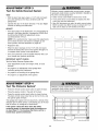
Limit adjustment settings regulate the points at which the
door will stop when moving up or down.
To operate the opener, press the Door Control push bar.
Run the opener through a complete travel cycle.
• Does the door open and close completely?
• Does the door stay closed and not reverse
unintentionally when fully closed?
If your door passes both of these tests, no limit
adjustments are necessary unless the reversing test fails
(Adjustment Step 3, page 29).
Adjustment procedures are outlined below. Read the
procedures carefully before proceeding to Adjustment
Step 2. Use a screwdriver to make limit adjustments. Run
the opener through a complete travel cycle after each
adjustment.
To prevent damageto vehicles, be sure fully open door
provides adequateclearance.
NOTE: Repeated operation of the opener during
adjustment procedures may cause the motor to overheat
and shut off. Simply wait 15 minutes and try again. If
anything interferes with the door's upward travel, it will
stop. If anything interferes with the door's downward travel
(including binding or unbalanced doors), it will reverse.
Cover Protection
Bolt
O
O
HOW AND WHEN TO ADJUST THE LIMITS
• If the door does not open completely
least five feet (1.5 m):
but opens at
Increase up travel. Turn the UP limit adjustment screw
clockwise. One turn equals 2" (5 cm) of travel.
NOTE: To prevent the trolley from hitting the cover
protection bolt, keep a minimum distance of 2-4"
(5 cm - 10 cm) between the trolley and the boll
Left Side Panel
Limit Adjustment
Screws
• If door does not open at least 5 feet (1.5 m):
o3to 1
Adjust the UP (open) force as explained in Adjustment
Step 2.
• If the door does not close completely:
ADJUSTMENT
LABEL
Increase down travel. Turn the down limit adjustment
screw counterclockwise. One turn equals 2" (5 cm) of
travel.
If the door reverses when closing and there is no
visible interference to travel cycle:
If door still won't close completely and the trolley bumps
into the pulley bracket (page 4), try lengthening the door
arm (page 25) and decreasing the down limit.
• If the opener reverses
If the opener lights are flashing, the Safety Reversing
Sensors are either not installed, misaligned, or
obstructed. See Troubleshooting, page 22.
in fully closed position:
Decrease down travel. Turn the down limit adjustment
screw clockwise. One turn equals 2" (5 cm) of travel.
Test the door for binding: Pull the emergency release
handle. Manually open and close the door. If the door is
binding or unbalanced, call for a trained door systems
technician. If the door is balanced and not binding,
adjust the DOWN (close) force. See Adjustment Step 2.
27
ADJUSTMENT
Adjust
the
STEP
2
Force
Without a properly installed safety reversal system, persons
(particularly small children) could be SERIOUSLYINJUREDor
KILLED by a closing garage door.
• Too much force on garage door will interfere with proper
operation of safety reversal system.
• NEVERincrease force beyond minimum amount required to
close garage door.
• NEVERuse force adjustments to compensate for a binding
or sticking garage door.
• If one control (force or travel limits) is adjusted, the other
control may also need adjustment.
• After ANY adjustments are made, the safety reversal system
MUST be tested. Door MUST reverse on contact with 1-1/2"
high (3.8 cm) object (or 2x4 laid flat) on floor.
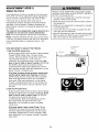
Force adjustment controls are located on the back panel
of the motor unit. Force adjustment settings regulate the
amount of power required to open and close the door.
If the forces are set too light, door travel may be
interrupted by nuisance reversals in the down direction
and stops in the up direction. Weather conditions can
affect the door movement, so occasional adjustment may
be needed.
The maximum force adjustment range is about 3/4 of a
complete turn. Do not force controls beyond that
point. Turn force adjustment controls with a screwdriver.
NOTE: If anything interferes with the door's upward travel,
it will stop. If anything interferes with the door's downward
travel (including binding or unbalanced doors), it will
reverse.
Force Adjustment
Controls
HOW AND WHEN TO ADJUST THE FORCES
1. Test the DOWN (close) force
Back Panel
• Grasp the door bottom when the door is about halfway
through DOWN (close) travel. The door should
reverse. Reversal halfway through down travel does
not guarantee reversal on a 1-1/2" (3.8 cm)
obstruction. See Adjustment Step 3, page 29. If the
door is hard to hold or doesn't reverse, DECREASE
the DOWN (close) force by turning the control
counterclockwise. Make small adjustments until the
door reverses normally. After each adjustment, run the
opener through a complete cycle.
• If the door reverses during the down (close) cycle
and the opener lights aren't flashing, INCREASE
DOWN (close) force by turning the control clockwise.
Make small adjustments until the door completes a
close cycle. After each adjustment, run the opener
through a complete travel cycle. Do not increase the
force beyond the minimum amount required to close
the door.
ADJUSTMENT LABEL
2. Test the UP (open) force
• Grasp the door bottom when the door is about halfway
through UP (open) travel. The door should stop. If the
door is hard to hold or doesn't stop, DECREASE
UP (open) force by turning the control
counterclockwise. Make small adjustments until the
door stops easily and opens fully. After each
adjustment, run the opener through a complete
travel cycle.
OpenForce
• If the door doesn't open at least 5 feet (1.5 m),
INCREASE UP (open) force by turning the control
clockwise. Make small adjustments until door opens
completely. Readjust the UP limit if necessary. After
each adjustment, run the opener through a complete
travel cycle.
28
Close Force
ADJUSTMENT
Test
the
Safety
STEP
3
Reversal
System
Without a properly installed safety reversal system, persons
(particularly small children) could be SERIOUSLYINJUREDor
KILLED by a closing garage door.
• Safety reversal system MUST be tested every month.
• If one control (force or travel limits) is adjusted, the other
control may also need adjustment.
• After ANY adjustments are made, the safety reversal system
MUST be tested. Door MUST reverse on contact with 1-1/2"
high (3.8 cm) object (or 2x4 laid flat) on the floor.
TEST
• With the door fully open, place a 1-1/2" (3.8 cm) board
(or a 2x4 laid flat) on the floor, centered under the
garage door.
• Operate the door in the down direction. The door must
reverse on striking the obstruction.
ADJUST
• If the door stops on the obstruction, it is not traveling far
enough in the down direction. Increase the DOWN limit
by turning the DOWN limit adjustment screw
counterclockwise 1/4 turn.
NOTE: On a sectional door, make sure limit adjustments
do not force the door arm beyond a straight up and
down position. See the illustration on page 25.
• Repeat the test.
• When the door reverses on the 1-1/2" (3.8 cm) board,
remove the obstruction and run the opener through 3 or
4 complete travel cycles to test adjustment.
• If the unit continues to fail the Safety Reverse Test, call
for a trained door systems technician.
IMPORTANT SAFETY CHECK:
Test the Safety Reverse System after:
• Each adjustment of door arm length, limits, or force
controls.
• Any repair to or adjustment of the garage door
(including springs and hardware).
(or a 2x4 laid flat)
• Any repair to or buckling of the garage floor.
• Any repair to or adjustment of the opener.
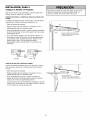
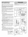
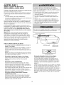
ADJUSTMENT
Test
The
Protector
STEP
4
System
®
Without a properly installed safety reversing sensor, persons
(particularly small children) could be SERIOUSLYINJUREDor
KILLED by a closing garage door.
• Press the remote control push button to open the door.
• Place the opener carton in the path of the door.
• Press the remote control push button to close the door.
The door will not move more than an inch (2.5 cm), and
the opener lights will flash.
The garage door opener will not close from a remote if the
indicator light in either sensor is off (alerting you to the fact
that the sensor is misaligned or obstructed).
If the opener closes the door when the safety
reversing sensor is obstructed (and the sensors are
no more than 6" (15 cm) above the floor), call for a
trained door systems technician.
Safety Reversing Sensor
29
Safety Reversing Sensor
OPERATION
IMPORTANTSAFETYINSTRUCTIONS
To reducethe risk of SEVEREINJURYor DEATH:
1. READAND FOLLOWALL WARNINGSAND INSTRUCTIONS.
2. ALWAYS keep remote controls out of reach of children. NEVER
permit children to operate or play with garage door control
push buttons or remote controls.
3. ONLYactivate garage door when it can be seen clearly, it
is properly adjusted, and there are no obstructions to door
travel.
4. ALWAYS keepgarage door in sight until completely closed.
NOONESHOULDCROSSTHE PATHOFTHE MOVINGDOOR.
5. NOONESHOULDGO UNDERA STOPPED,PARTIALLY
OPENEDDOOR.
6. If possible, use emergency releasehandle to disengagetrolley
ONLYwhen garage door is CLOSED.Weak or broken springs
or unbalanced door could result in an open door falling rapidly
and/or unexpectedly,causing SEVEREINJURYor DEATH.
7. NEVERuse emergency releasehandle unless garage doorway
is clear of persons and obstructions.
8. NEVERuse handle to pull garage door open or closed. If rope
knot becomes untied, you could fall.
Using
Your
Garage
Door
9. If one control (force or travel limits) is adjusted, the other
control may also need adjustment.
10. After ANY adjustments are made, the safety reversal system
MUST be tested.
11. Safety reversal system MUST be tested every month. Garage
door MUST reverse on contact with 1-1/2" high (3.8 cm)
object (or a 2x4 laid flat) on the floor. Failureto adjust the
garage door opener properly may cause SEVEREINJURY or
DEATH.
12. ALWAYSKEEPGARAGEDOORPROPERLYBALANCED
(see page 3). An improperly balanced door may NOT reverse
when required and could result in SEVEREINJURY or
DEATH.
13. ALL repairs to cables, spring assemblies and other
hardware, ALL of which are under EXTREMEtension, MUST
be made by a trained door systems technician.
14. ALWAYSdisconnect electric power to garage door opener
BEFOREmaking ANY repairs or removing covers.
15SAVETHESEINSTRUCTIONS•
6. If obstructed while opening, the door will stop.
7. If fully open, the door will not close when the beam is
broken. The sensor has no effect in the opening cycle.
Opener
Your Security+ _"opener and hand-held remote control
have been factory-set to a matching code which changes
with each use, randomly accessing over 100 billion new
codes. Your opener will operate with up to eight
Security+ _"remote controls and one Security+ _"Keyless
Entry System. If you purchase a new remote, or if you
wish to deactivate any remote, follow the instructions in
the Programming section.
If the sensor is not installed, or is misaligned, the door
won't close from a hand-held remote. However, you can
close the door with the Door Control, the Outdoor Key
Switch, or Keyless Entry, if you activate them until down
travel is complete. If you release them too soon, the door
will reverse.
The opener lights will turn on under the following
conditions: when the opener is initially plugged in; when
power is restored after interruption; when the opener is
activated. They will turn off automatically after 4-1/2
minutes. Bulb size is A19. Power is 100 watts maximum.
Lights will also turn on when someone walks through the
open garage door.
Activate your opener with any of the following:
• The hand-held Remote Control: Hold the large push
button down until the door starts to move.
• The waft-mounted Door Control: Hold the push button
or bar down until the door starts to move.
• The Keyless Entry (See Accessories): If provided with
your garage door opener, it must be programmed
before use. See Programming.
When the opener is activated (with the safety
reversing sensor correctly installed and aligned)
1. If open, the door will close. If closed, it will open.
2. If closing, the door will reverse.
3. If opening, the door will stop.
4. If the door has been stopped in a partially open
position, it will close.
5. If obstructed while closing, the door will reverse. If the
obstruction interrupts the sensor beam, the opener
lights will blink for five seconds.
30
Using
the
Wall-Mounted
Door
To Open
Control
Press the lighted push button to open
or close the door. Press again to
reverse the door during the closing
cycle or to stop the door while it's
opening.
the
Door
Manually
To prevent possible SERIOUSINJURYor DEATHfrom a falling
garage door:
• If possible, use emergency releasehandle to disengage
trolley ONLYwhen garage door is CLOSED.Weak or broken
springs or unbalanceddoor could result in an open door
falling rapidly and/or unexpectedly.
• NEVERuse emergency releasehandle unless garage
doorway is clear of persons and obstructions.
• NEVERuse handle to pull door open or closed. If rope knot
becomes untied, you could fall.
DISCONNECT
THE TROLLEY:
The door should be fully closed
if possible. Pull down on the
emergency release handle (so
that the trolley release arm
snaps into a vertical position)
and lift the door manually. The
lockout feature prevents the
trolley from reconnecting
automatically, and the door can
be raised and lowered
manually as often as
necessary.
Trolley
Re,ea2
- 're
(In Manual
Disconnect
Position)
I
Lockout position
(Manual disconnect)
TO RE-CONNECT
TROLLEY:
THE
Pull the emergency release
handle toward the opener at
an angle so that the trolley
release arm is horizontal. The
trolley will reconnect on the
next UP or DOWN operation,
either manually or by using
the door control or remote.
Trolley
Release Handle _'-_, ._
(Down and Back) , ,_'._._"
To reconnect
31
Care
of Your
Garage
Door
Opener
THE REMOTE CONTROL BATTERY
LIMIT AND FORCE ADJUSTMENTS:
Weather conditions may cause
some minor changes in door
operation requiring some
re-adjustments, particularly
during the first year of operation.
Pages 27 and 28 refer to the
limit and force adjustments. Only
a screwdriver is required. Follow
the instructions carefully.
FORCE CONTROLS
To prevent possible SERIOUSINJURYor DEATH:
• NEVERallow small children near batteries.
• If battery is swallowed, immediately notify doctor.
To reduce risk of fire, explosion or chemical burn:
• ReplaceONLYwith 3V2032 coin batteries.
• DONOT recharge, disassemble, heat above 100°C (212°F)
or incinerate.
LIMIT CONTROLS
Repeat the safety reverse test
(Adjustment Step 3, page 29)
after any adjustment of limits or force.
The lithium battery should produce
power for up to 5 years.
MAINTENANCE
To replace battery, use the visor
clip or screwdriver blade to pry
open the case as shown. Insert
battery positive side up (+).
SCHEDULE
Open this end
,,,,,_.._
first to av0id/,___m<..__
cracking _
<__/
j-'_
hously
Every Month
Dispose of old battery properly.
• Manually operate door. If it is unbalanced or binding, call
a trained door systems technician.
Replace the battery with only 3V2032 coin cell batteries.
• Check to be sure door opens & closes fully. Adjust limits
and/or force if necessary. (See pages 27 and 28)
NOTICE:To comply with FCCand or Industry Canadarules (IC),adjustment or modifications of this
receiver and/or transmitter are prohibited, except for changing the code setting or replacing the
battery.THEREARE NOOTHERUSERSERVICEABLEPARTS.
Tested to Comply with FCCStandards FORHOME OR OFFICEUSE, Operation is subject to the
following two conditions: (1) this device may not cause harmful interference, and (2) this device
must acceptany interference received,including interferencethat may cause undesiredoperation,
• Repeat the safety reverse test. Make any necessary
adjustments. (See Adjustment Step 3)
Two Times a Year
• Check chain tension. Disconnect trolley first. Adjust if
necessary. (See page 11)
Every Year
• Oil door rollers, bearings and hinges. The opener does
not require additional lubrication. Do not grease the door
tracks.
32
Having
a Problem?
1. My door will not close and the light bulbs blink on
my motor unit: The safety reversing sensor must be
connected and aligned correctly before the garage door
opener will move in the down direction.
Bell Wire
.....--__
1
• Verify the safety sensors are properly installed, aligned
and free of any obstructions. Refer to Installation Step
10: Install The Protector SysterrP.
• Check diagnostic LED for flashes on the motor unit
then refer to the Diagnostic Chart on the following
page.
Diagnostic _L_J
i
2. My remotes will not activate the door:
• Reprogram remotes following the programming
instructions. Refer to Programming.
-'-'-Safety Reversing Sensor
• If remote will still not activate your door, check
diagnostic LED for flashes on motor unit then refer to
Diagnostic Chart on the following page.
Sending Eye Safety Reversing
Sensor (Amber Indicator Light)
Receiving EyeSafety Reversing
Sensor (Green Indicator Light)
3. My door reverses for no apparent reason: Repeat
safety reverse test after adjustments to force or travel
limits. The need for occasional adjustment for the force
and limit settings is normal. Weather conditions in
particular can affect door travel.
• Manually check door for balance or any binding
problems.
6. My motor unit hums briefly:
• First verify that the trolley is against the stop bolt.
• Refer to Adjustment Step 2, Adjust the Force.
• Release the door from the opener by pulling the
Emergency Release Rope.
• Manually bring the door to a closed position.
4. My door reverses for no apparent reason after fully
closing and touching the floor: Repeat safety reverse
test after adjustments to force or travel limits. The need
for occasional adjustment for the force and limit settings
is normal. Weather conditions in particular can affect
door travel.
• Loosen the chain by adjusting the outer nut 4 to 5
turns. This relieves the tension.
• Run the motor unit from the remote control or door
control. The trolley should travel towards the door and
stop. If the trolley re-engages with the door, pull the
Emergency Release Rope to disengage.
• Refer to Adjustment Step 1, Adjust the UP and DOWN
Travel Limits. Decrease down travel by turning down
limit adjustment screw clockwise.
• Decrease the UP travel by turning the UP Travel
adjustment screw 2 full turns away from the arrow.
• Re-tighten the outer nut so the chain is a 1/4" (6 mm)
above the base of the rail. (When the door is
reconnected and closed, the chain will sag. This is
normal.)
5. My lights will not turn off when door is open:
• The garage door opener is equipped with a security
light feature. This feature activates the light on when
the safety sensor beam has been obstructed.
• If the trolley does not move away from the bolt, repeat
the steps above.
33
Bell Wire
Safety Reversing
Diagnostic
Your garage door opener is programmed with
self-diagnostic capabilities. The "Learn" button/diagnostic
LED will flash a number of times then pause signifying it has
found a potential issue. Consult Diagnostic Chart below.
Sensor
Chart
"e
Safety reversing sensors
wire open (broken or
disconnected).
Symptom: One or both of the Indicator lights on the safety sensors do
not glow steady.
• Inspect sensor wires for a short (staple in wire), correct wiring polarity (black/white
wires reversed), broken or disconnected wires, replace/attach
as needed.
OR
• Disconnect all wires from back of motor unit.
• Remove sensors from brackets and shorten sensor wires to 1-2 ft (30-60 cm) from
back each of sensor.
• Reattach sending eye to motor unit using shortened wires. If sending eye indicator
light glows steadily, attach the receiving eye.
Safety reversing sensors
wire shorted or black/
white wire reversed.
• Align sensors, if the indicator lights glow replace the wires for the sensors. If the
sensor indicator lights do not light, replace the safety sensors.
"e
Symptom: LED is not fit on door control.
• Inspect door control/wires for a short (staple in wire), replace as needed.
Door control or
wire shorted.
• Disconnect wires at door control, touch wires together. If motor unit activates,
replace door control.
• If motor unit does not activate, disconnect door control wires from motor unit.
Momentarily short across red and white terminals with jumper wire. If motor unit
activates, replace door control wires.
"e
Safety reversing sensors
slightly misaligned
(dim or flashing LED).
Symptom: Sending indicator light glows steadily, receiving indicator light is
dim or flashing.
• Realign receiving eye sensor, clean lens and secure brackets.
• Verify door track is firmly secured to wall and does not move.
Symptom: Motor has overheated; the motor unit does not operate or
trolley is stuck on stop bolt = Motor unit hums briefly; RPM Sensor =
Short travel 6-8" (15-20 cm).
Motor overheated or
possible RPM sensor
failure. Unplug to reset.
• Unplug unit to reset. Try to operate motor unit, check diagnostic code.
• If it is still flashing 5 times and motor unit moves 6-8" (15-20 cm), replace
RPM sensor.
• If motor unit doesn't operate, motor unit is overheated. Wait 30 minutes and retry. If
motor unit still will not operate replace logic board.
"e
Motor Circuit Failure.
Replace Receiver
Logic Board.
Symptom: Motor un# doesn't operate.
• Replace logic board because motor rarely fails.
34
PROGRAMMING
NOTICE: If this Security.J_ garage door opener is operated with a non-rolling code transmitter, the technical measure in
the receiver of the garage door opener, which provides security against code-theft devices, will be circumvented. The
owner of the copyright in the garage door opener does not authorize the purchaser or suppfier of the non-rolling code
transmitter to circumvent that technical measure.
Your garage door opener has already been programmed at the factory to operate with your hand-held remote control.
The door will open and close when you press the large push button.
Below are instructions for programming your opener to operate with additional Security+ _R_
remote controls.
To Add
USING THE "LEARN"
or Reprogram
a Hand-held
Remote
Control
BUTTON
To Erase
Motor
All Codes From
Unit Memory
To deactivate any unwanted remote, first
erase all codes:
Press and hold the "learn" button on motor
unit until the learn indicator light goes out
(approximately 6 seconds). All previous
codes are now erased. Reprogram each
lote or keyless
entry you wish to use.
*3-Function
1. Press and release the "learn" button
on the motor unit. The learn
indicator light will glow steadily for
30 seconds.
Remotes
If provided with your garage door opener, the large button
is factory programmed to operate it. Additional buttons on
any Security÷ _R_
3-Function
remote or compact remote
_
_
can be programmed to
operate other Security÷ <R_
garage door openers.
2. Within 30 seconds, press and hold
the button on the hand-held remote*
that you wish to operate your
garage door.
3. Release the button when the motor
unit lights blink. It has learned the
code. If light bulbs are not installed,
two clicks will be heard.
35
To Add,
Reprogram
or Change
a Keyless
Entry
PIN
NOTE: Your new Keyless Entry must be programmed to operate your garage door opener.
USING THE "LEARN"
BUTTON
To set a temporary
PIN
You may authorize access by visitors or service people
with a temporary 4-digit PIN. After a programmed number
of hours or number of accesses, this temporary PIN
expires and will no longer open the door. It can be used to
close the door even after it has expired. To set a
temporary PIN:
1. Press the four buttons for your personal entry PIN (not
the last temporary PIN), then press and hold the 8
button.
The opener light will blink three times. Release the
button.
2. Press the temporary 4-digit PIN you have chosen, then
press Enter.
1. Press and release the "learn" button
on motor unit. The learn indicator
light will glow steadily for 30
seconds.
The opener light will blink four times.
3. To set the number of hours this temporary PIN will
work, press the number of hours (up to 255), then
press 8.
OR
2. Within 30 seconds, enter a four digit
personal identification number (PIN)
of your choice on the keypad. Then
press and hold the ENTER button.
3. Release the button when the motor
unit lights blink. It has learned the
code. If light bulbs are not installed,
two clicks will be heard.
3. To set the number of times this temporary PIN will work,
press the number of times (up to 255), then press #.
The opener light will blink once when the temporary PIN
has been learned.
\1
Test by pressing the four buttons for the temporary PIN,
then press Enter. The door should move. If the temporary
PIN was set to a certain number of openings, remember
that the test has used up one opening.To clear the
temporary password, repeat steps 1-3, setting the number
of hours or times to 0 in step 3.
/
To change an existing, known PIN
One Button Close: Opener can be closed by pressing
only the ENTER button if the one button close feature has
been activated. This feature has been activated at the
factory. To activate or deactivate this feature press and
hold buttons 1 and 9 for 10 seconds. The keypad will blink
twice when the one button close is active. The keypad will
blink four times when one button close is deactivated.
If the existing PIN is known, it may be changed by one
person without using a ladder.
1. Press the four buttons for the present PIN, then press
and hold the # button.
The opener light will blink twice. Release the # button.
2. Press the new 4-digit PIN you have chosen, then
press Enter.
The motor unit lights will blink once when the PIN has
been learned.
Test by pressing the new PIN, then press Enter. The door
should move.
36
REPAIR
Rail
PARTS
Assembly
Parts
3
Installation
KEY
NO.
PART
NO.
DESCRIPTION
1
4A1008
Master link kit
2
41C5141-1
Complete trolley assembly
3
41A5665-2
Complete rail
4
5
144C56
41A5807
Idler pulley
Chain and cable
6
12D598-1
"U" bracket
NOT SHOWN
183A163
Wear pads
Parts
1
2
KEY
NO.
PART
NO.
DESCRIPTION
1
41A4899
Standard control console
2
10A20
3V 2032 Lithium battery
3
41 A6140-3
3-function remote control housing
(no circuit board)
4
29B137
Visor clip
5
41A2828
Emergency release rope and handle
assembly
6
41A5047-2
7
41 B4494-1
Header bracket w/clevis pin and fastener
2-Conductor bell wire: white and white/
red
8
41A5047
9
178B35
Door bracket w/clevis pin and fastener
Curved door arm section
10
7
11
178B34
Straight door arm section
11
12B776
Hanging bracket
12
41A5034
Safety sensor kit: receiving and sending
eyes with 3' (.9 m) 2-conductor
bell wire attached
13
41A5266-1
Safety sensor bracket
NOT SHOWN
41A5258-25
Installation hardware bag (includes
hardware listed on page 7)
Owner's manual
114A3613
37
Motor
Unit
Assembly
Parts
2
18O
O
O
19
/
8
/
17
/
9
15
/
/
I
I
Brown
Wire
(Down)
Contact
_ f"rh_
LIMITSWITCH
ASSEMBLY
/
/
/
11
I
i
_
.Gre7
Drive __,__
Gear V.......
KEY
NO.
Center Umit
(Up)
Contact
Contact
PART
NO.
_
Yellow
Wire
DESCRIPTION
KEY
NO.
PART
NO.
DESCRIPTION
1
41A5615
Chain Spreader
12
41A5525-63
Cover
2
41 C4220A
Gear and sprocket assembly
Complete with: Spring washer,
thrust washer, retaining ring,
bearing plate, roll pins (2), drive
gear and worm gear, helical gear
w/retainer and grease
13
14
41A2818
Limit switch drive & retainer
41 D3452
Limit switch assembly
15
16
17
41A2822-1
Interrupter cup assembly
41 C4398A
RPM sensor assembly
41AC150-1M
Receiver logic board assembly.
Complete with: Logic board,
end panel w/all labels, light
socket
41A2817
4
41 B4245
Drive/worm gear kit w/grease,
roll pins (2)
Line cord
5
41 A5484-5
End panels w/all labels
18
6
4A1344
41 C5497
41 C5498
7
108D77
Light socket
Lens
High voltage wire harness
Low voltage wire harness
19
41D 179
End panel w/all labels
8
30B532
Capacitor-
9
12A373
Capacitor bracket
41A2826
NOT SHOWN
Motor shaft bearing kit
10
41A3150
Terminal block w/screws
11
41 D3058
Universal replacement motor &
bracket assembly,'
Complete with: Motor, worm,
bracket, bearing assembly, RPM
sensor
1/2 HP
41 A2825
38
Opener assembly hardware kit
(includes screws not
designated by a number in
illustration)
ACCESSORIES
139.53702
139.53753
Emergency Key Release:
f
Required for a garage with NO
access door. Enables homeowner to
open garage door manually from
outside by disengaging trolley.
139.53726
Includes visor clip.
139.53752
8 Foot (2.4 m) Rail Extension
To allow an 8 (2.4 m) foot door to
open fully.
139.53727
139.53754
Security,IF _Keyless Entry:
Enables homeowner to operate garage
door opener from outside by entering a 4
digit code on specially designed keypad.
139.53687
Premium Control
10 Foot (3 m) Rail Extension:
Support Brackets:
Extension Brackets:
(Available only through Sears
Parts & Service)
(Optional) For safety sensor
installation onto the wall or floor.
139.53709
Console:
Provides a lock feature to prevent
operation of garage door from portable
remotes. A light feature controls the
opener lights. Can be used to program
the opener to accept additional remotes.
For finished ceilings or where
additional support is required, based
on garage construction. Includes
brackets and fastening hardware.
41A5281
Secu rity+ <R_
Compact 3-Fu nction
Remote Control:
With loop for attaching key ring.
To allow a 10 (3 m) foot door to
open fully.
139.53589
Security.F R_
3-Function Remote
Control:
139.53749
Plug-In Light Control:
Enables homeowner to turn on a
lamp, television or other appliance
from car, bedside, or anywhere in the
home with a remote.
Door Clearance Brackets:
(For Sectional Doors Only)
Replaces top brackets and rollers on
door to reduce height of door travel.
For use when installing opener in
garage with low headroom clearance.
WARRANTY
CRAFTSMAN
GARAGE
DOOR OPENER
LIMITED WARRANTY
90-DAY IN-HOME FULL WARRANTY ON PRODUCT
For 90 days from the date of purchase, this product will be repaired, free of charge, if defective in material or workmanship.
ADDITIONAL
LIMITED WARRANTY
ON PARTS
From the 91st day up to 1 year from the date of purchase, replacement parts for any defective parts on this product will be furnished,
charge. You pay for labor.
ADDITIONAL
LIMITED WARRANTY
ON MOTOR
From the 91st day and through 4 years, if the motor on this product is defective, a replacement
for labor.
WARRANTY
RESTRICTION
motor will be furnished
free of
free of charge. You pay
This Craftsman Garage Door Opener Limited Warranty does not cover light bulbs or repair parts necessary because of operator abuse or
negligence, including the failure to install, adjust and operate this garage door opener according to instructions contained in the owner's manual.
This limited warranty also does not cover any problems caused by interference.
LIMITATION
ON LIABILITY
Seller will not be liable for loss or damage to property or any incidental or consequential loss or expense from property damage due directly or
indirectly to the use of this product. Some states do not allow the exclusion or limitation of incidental or consequential damages, so the above
limitation or exclusion may not apply to you.
DISCLAIMER
OF IMPLIED
WARRANTIES
Except for the motor, all implied warranties for this product, including but not limited to any implied warranties of merchantability and fitness for a
particular purpose, are limited in duration to the 91st day through 1-year limited warranty period set forth above. All implied warranties with
respect to the motor are limited in duration to the 91st day through 4-year limited warranty period set forth above. No implied warranties will exist
or apply after such periods. Some States do not allow limitations on how long an implied warranty lasts, so the above limitations may not
apply to you.
WARRANTY
SERVICE
IS AVAILABLE
BY CALLING
1-800-4-MY-HOME
_.
This warranty applies only while this product is in use in the United States.
This warranty gives you specific legal rights, and you may also have other rights which vary from state to state.
Sears, Roebuck and Co., Dept. 817WA, Hoffman Estates, IL 60179
39
CONTENIDO
Introducci6n
Revisi6n
2-7
de los sfmbolos y terminos
Preparaci6n
Ajustes
de seguridad ......... 2
de la puerta de su cochera .........................
Herramientas
necesarias
................................................
Planificaci6n
................................................................
3
Ajuste la fuerza .............................................................. 28
3
Pruebe el sistema de retroceso de seguridad .............. 29
Pruebe La Sistema de Protecci6n ®............................... 29
4-5
Inventario
de la caja de cart6n ........................................
6
Inventario
de piezas ........................................................
7
Montaje
27.29
Ajuste el limite del recorrido .......................................... 27
8-11
Operaci6n
30-34
Instrucci6nes de seguridad para la operaci6n .............. 30
C6mo usar su abridor de puerta de cochera ................ 30
Monte el riel y instale el trole ..........................................
8
C6mo usar la unidad de control de pared ..................... 31
Fije el riel a la unidad del motor ......................................
9
C6mo abrir la puerta manualmente ............................... 31
Instale la polea Ioca ........................................................
9
Mantenimiento de su abridor de puerta de cochera ..... 32
10
Si tiene algQn problema ................................................ 33
11
Tabla de diagn6stico ...................................................... 34
Instale la cadena y cable
.............................................
Apriete la cadena ..........................................................
Instalaci6n
11-26
Instrucci6nes
de seguridad
para la instalaci6n
C6mo
............. 11
Programar
el Abridor
35-36
C6mo agregar o reprogramar un
control remoto manual ................................................... 35
Determine d6nde va a instalar
la mensula del cabezal ..................................................
12
Instale la mensula del cabezal ......................................
13
Coloque
el riel en la mensula del cabezal ....................
14
Coloque
el abridor
15
C6mo agregar, reprogramar o cambiar un
c6digo de entrada sin Ilave ........................................... 36
Cuelgue
el abridor .........................................................
16
Accesorios
37
Garantia
37
en posici6n ......................................
Instale la unidad de control de la puerta .......................
17
Instale la luz ..................................................................
18
Instale la manija y la cuerda de emergencia
Requisitos
para la instalaci6n
Instale La Sistema
................ 18
electrica .........................
de Protecci6n _ ...........................
Nbmeros
de Servicio
Contratapa
19
20-22
Fije la mensula de la puerta .....................................
23-24
Conecte
25-26
el brazo de la puerta al trole ......................
C6mo borrar todos los c6digos ..................................... 35
Controles remotos de 3 funciones ................................ 35
INTRODUCClON
Revisi6n
de los Simbolos
de Seguridad
y T_rminos
Este abridor de puerta de cochera ha sido disefiado y probado para un funcionamiento seguro, siempre y cuando se instate, se
pruebe, se opere y se le de mantenimiento como se indica en este manual, cumptiendo at pie de la letra con todas las advertencias
instrucciones generates aqui contenidas.
Mecanica
Electrica
e
Estas advertencias y/o simbolos de seguridad que aparecen en
este manual le alertara.n de que existe el riesgo de una lesion
$eria o de muerte si no se siguen las instrucciones
correspondientes. El petigro puede ser etectrico (electrocucion) o
meca.nico. Lea las instrucciones con mucho cuidado.
Cuando vea esta patabra y/o simbolo de seguridad en este
manual, le alertara, de que existe et riesgo de dafiar la puerta de
la cochera y/o el abridor si no se siguen las instrucciones
correspondientes. Lea las instrucciones con mucho cuidado.
Preparacibn
de la puerta
de su cochera
Antes de comenzar:
Para evitar una LESIONGRAVEo INOLUSOLA MUERTE:
• Quite los seguros.
• Retire cuatquier cuerda o cable que este conectadoa
• SIEMPRE Ilame a un t_cnico profesional para que le d_ servicio a
su puerta de cochera si _sta se atora, se pandeao est,.
desbalanceada.Una puerta de cochera que no est_ bien balanceada
puede que NO retroceda como se requiere.
• NUNCAintente aflojar, mover ni ajustar la puerta de su cochera, los
resortes de la puerta, los cables, las poleas, las m_nsulas ni la
tornilleria, puestodos estos elementos est_.nbajo tensi6n
EXTREMA.
la puerta.
• Haga la siguiente prueba con su puerta para verificar que
este batanceada y que no se atore ni se pandee:
1. Levante la puerta hasta la mitad de su recorrido como se
muestra. Suelte ta puerta. Siesta. balanceada, debera.
mantenerse en esa posicion con solo el soporte de los
resortes.
• Quite TODOSlos seguros y retire TODASlas cuerdas conectadas a
la puerta de cochera ANTES de instalar y operar el abridor de la
puerta de cochera para evitar que se enreden.
2. Suba y baje la puerta; observe si se atora con atgo o si se
pandea.
Si su puerta se atora o se pandea, o no est& balanceada
Ilame a un tecnico especiatizado en sistemas de puertas.
Para evitar que se darien el puerta y el abridor:
• SIEMPREquite los seguros ANTESde instalar y/o de operar el
abridor.
• SOLAMENTEopere el abridor de puerta de cochera con corriente de
120V, 60Hz con objeto de evitar su mal funcionamiento y que el
abridor se dafie.
Puerta seccional
Puerta de una sola pieza
Herramientas
necesarias
Durante et montaje, instalacion y ajuste det abridor, las
instrucciones le indicar&n como usar las herramientas que
aparecen en la siguiente ilustracion.
L_piz
Sierra de mano
Cinta de medir
Cortadora de alambre
Taladro
Brocas de 3/16, 5/16
y 5/32depulgada
Destornillador
....
Escalera
U8
7/16, 9/16y
1/4de p'ulgada
Llave inglesa
Planificaci6n
Identifique la aitura y et tipo de su puerta de cochera. Revise et
a.rea de su cochera y observe si atguna de las siguientes
instalaciones corresponden a la suya. A veces se requieren
materiates adicionales, as[ que tat vez sea conveniente tenet
esta hoja y las ilustraciones correspondientes a mano cuando
inicie la instalacion de su abridor.
Dependiendo de sus necesidades individuales, es posibte que
en atgunos casos vaya a necesitar materiates o herramientas
que no se inciuyen con este producto.
Observe et punto donde la puerta hace contacto con et piso.
El espacio entre la base de la puerta y el piso no debe
exceder 6 mm (1/4 de putgada). Si no es asf, se corre el
riesgo de que et sistema de retroceso de emergencia no
funcione correctamente. Vea Ajustes, Paso 3. Sera. necesario
reparar ya sea et piso o la puerta.
INSTALAClON
CON UNA PUERTA SECClONAL
Instatacion Paso 1 - Observe la pared o et cielo raso justo por
encima de la puerta de la cochera. La mensula det cabezal
debe estar firmemente sujeta a los soportes de la estructura.
• Si tiene una puerta de acero, aluminio, fibra de vidrio o con
panetes de vidrio, necesitar& refuerzos verticaies y
horizontales en la puerta. (Instatacion, Paso 11.)
Instalacion Paso 5 - Si el ptaf6n o cieto raso de su cochera
tiene acabado, es posibte que necesite una mensuta de
soporte y/o ma.s pemos y tomilterfa para la instalacion.
• El abridor se debe instalar pot encima det centro de la puerta,
pero si existe algQn resorte de tension o ptaca de apoyo en el
paso de la mensuta del cabezal, se puede instaiar hasta a
1.22 m (4 pies) a la derecha o a la izquierda det centro de la
puerta. Vea Instatacion, Pasos det 1 at 11.
Instatacion Paso 10 - Dependiendo del tipo de construccion
de su cochera, es posibte que necesite mensutas de
extension o btoques de madera para instalar los sensores.
• Si su puerta es de ma.s de 2.13 m (7 pies) de attura, yea
Extensiones de riel en la seccion de Accesorios.
Instatacion Paso 10 - El montaje en el piso del sensor que
activa et sistema de retroceso de seguridad podrfa requerir
piezas que no se incluyen.
• 6Hay otra puerta que de acceso a la cochera? Si no es as[,
sera. necesario contar con el sistema de llave de emergencia
Modeto 53702. Vea la pa.gina de Accesorios.
INSTALAClON
CON UNA PUERTA SECClONAL
CIELO RASO CON ACABADO
Los refuerzosverticales y horizontalesson
necesariospara laspuertas de cochera de
materialesmas livianos(fibra devidrio, acero,
aluminio,o puertas con panelesde vidrio).
Veala pagina 23, donde encontraramas detalles.
Pared delantera
Se requiere mensulade
soporte y tornillos o
sujetadores.Vea la pagina 16.
La holguraen la tensi6n
de la cadenaes normal
cuando la puerta se
encuentracerrada
Riel
Resortede extensi6n
0
Unidad del motor
Resortede torsi6n
Puertade
acceso
Vertical de la
Puertade Garaje
Unidad de
control de la
puerta,
instalada
en la pared
7]
Mensula
//I
del cabezal
/
Perno de
0
I
_arde
_OoO°_Bra.zo,
£W.J)
Sensor de seguridad
de reversa
El espacio entrela base de
la puerta y el piso nodebe de
exceder6 mm (1/4 de pulg.).
Sensor de seguridad
de reversa
EN POSICl0N CERRADA
/_/
/_/
_N[___
HI
_
\
Cadena
/_ rec'°°? I-- Cuerda
y manija
--
lapuerta I
d_
"
_ Braze
.curvo
de
i'_ I Uensula lapuerta
] I dela
j i_l puer[a
del sistemade
liberaci6n
de emergencia
Planificaci6n
INSTALACION
(continba)
CON PUERTAS DE UNA SOLA PIEZA
Sin un sistema de retroceso de seguridad que funcione debidamente,
al cerrar la puerta de la cochera se corre el riesgo de que las
personas (yen particular los nifios pequefios) sufran LESIONES
GRAVESo INCLUSOLA MUERTE.
• Generatmente una puerta de una sota pieza no requiere
refuerzos adicionates. Si usted tiene una puerta de material
liviano y quiere reforzarla, consulte ta informacion respecto a
puertas seccionates, contenida en Instalacion, Paso 11.
• El espacio entre la basede la puerta de la cochera y el piso NO
DEBEexceder 6 mm (1/4 de pulgada). De no ser asi, el sistema de
retroceso de seguridad NO va a funcionar debidamente.
• El piso o la puerta de la cochera se DEBEreparar para eliminar este
espacio.
• Dependiendo del disefio de su puerta, tal vez necesite
piezas de montaje adicionates para la mensula de la puerta
(Paso 11).
PUERTA DE UNA SOLA PIEZA
SIN CARRIL
CIELORASO CON ACABADO
Se requiere mensuiade soporte
y tornitloso sujetadores.
Veata p_tgina16.
Riel
Pareddelantera
La holgura en la tensi6n
de la cadena es normal
cuando la puerta se
encuentracerrada
Unidaddel motor
Unidadde control de la puerta,
instaladaen la pared
f
Puertade
acceso
EN POSICIONCERRADA
Perno de paro
del trole
Sensor de seguridad
de reversa
Sensor de seguridad
de reversa
El e,_ _acioentre la base
la puerta y el piso nodebe de
exceder 6 mm (1/4 de pulg.)
\\\x t
x_._.'_
_Vpuerta
x"N_'_
I
Cable
_razo
recto de
Trole
--
Braze
curvo
_er_
Ouerda y manija
del sistemade
liberaci6nde
emergencia
lacochera
PUERTA DE UNA PIEZA CON CARRIL
EN POSICION CERRADA
Perno de pare
K/Z/
K/l/
v///
Puertade
acceso
E
/\
ot
Pare
delantera
Sensorde seguridad
de reversa
El espacioentre la base de
la puerta y el piso no debe
exceder 6 mm (1/4 de pulg.).
Sensor de seguridad
de reversa
1
Cable
Cadena
d_trole _
Mensula
Brazo ,
_
de,
caboza,
ooooooooooo) j
_'_""
_i_
///Zl
7/-'/_
_/l_la
Mensulade
la puerta
Puertade
cochera
I
_'_,7
Brazerecto de
la puerta
I
I
I
I
I_
I
C]_
Re,
Cuerdavm_ "
uer a yy manlja
uueraa
ms,
!.,el_El.erra de
liberaci6n .
de emergencla
Inventario
de la Caja
de Cart6n
Su abridor viene empacado en una caja de carton que contiene
el motor y las piezas que se muestran en la siguiente ilustracion.
Tome nota de que los accesorios dependera.n det modeto que
haya comprado. Si falta alguna pieza, revise con cuidado et
material de empaque ya queen ocasiones las piezas se atoran
en et mismo. Toda la tornilleria y las piezas necesarias para et
montaje e instalacion de su puerta se itustran en ta siguiente
pa.gina. Conserve la caja y los materiates de empaque hasta que
la instatacion y el ajuste se hayan terminado.
Desplegadorde Cadena
Consola de Control Estandar
SECURITY+®
Control remotode 3 Funciones
con clip para el visor (2)
%
_Io
%
%
Trole
Unidaddel motor con uno lente
Seccionescentral
y posterior del riel
9o
Mensulaspara colgar
@
Polea de la cadena
Cadenay cable
Secci6ndelantera
del riel (cabezal)
J
Secci6ncurva del
brazode la puerta
Mensuladel cabezal
Mensulade la puerta
O--Dos
cables conductores
de campana. Blancoy blanco/rojo
Sensoresdel sistemade retroceso
de seguridad (2)
ProtectorSystem®
Dossensores del sistemade
retrocesode seguridad (un ojo transmisor
y un ojo receptor) conectadosa uncable
de campana de dos conductores.
Blanco y blancoy negro
Etiquetasde
seguridady
literatura
Secci6n recta
del brazo de
la puerta
Inventario
de Piezas
Antes de la instatacion, organice todas las piezas en grupos como se muestra en la siguiente ilustracion.
TORNILLERiA
Tuercade
1/4-20 (2)
Y PIEZAS PARA EL MONTAJE
Arandelade 5/8 pulg. (2)
Arandela de
3/8 pulg, (1)
Tuercade
3/8 pulg,(1)
1
Perno de
1/4-20xl-3/4 pulg, (2)
Enlace maestro(2)
Separader(2)
Perno de 1/4-20x2-1/2de pulg,(1)
PernoIoco (1)
Flecha roscada del trole (1)
TORNILLERJA
Y PIEZAS PARA LA INSTALACION
O
Perno de coche
de 1/4-20xl/2 pulg.(2)
Tuercade mariposa
1/4-20pulg, (2)
Anillo sujetador(3)
Tuercade
5/16-18pulg, (6)
Perno hexagonal
de 5/16-18x7/8pulg. (4)
IIIIIIIIIII1 >
Tornillode cabeza cuadrada
Arandelade 5/16pulg. (5)
Manija
Grapa con
aislamiento (30)
lllllMIMl,l,lllllllllllll
Tornillo6ABx1-1/4 pulg.(2)
Tornillode 6-32xl pulg. (2)
de 5/16-18xl-7/8 pulg,(2)
Cuerda
de 1/4-14x5/8 de pulg.(2)
Taquetepara inure falso (2)
o,
Pasador dechaveta
de 5/16x1-1/2 pulg,(1)
Pasadorde chaveta
de 5/16x1-1/4pulg. (1)
oD
Pasador de chaveta
de 5/16xl pulg, (1)
MONTAJE,
Monte
el Riel
PASO
1
e instale
el Trole
No encienda ni use el abridor hasta que Ilegue al paso de la
instalacibn correspondiente, de otra manera corre el riesgo
de complicar el proceso de instalacibn.
El riel delantero tiene una "ventana" cortada en el extremo de la
puerta (vea la ilustraci6n). El orificio que se encuentra por
encima de esta ventana es mas grande en la parte superior
del riel que en la parte inferior. Hay un orificio mas pequeho que
se encuentra a 8.9 cm (3-1/2 pulg.) y esta cerca de la orilla del
riel. Gire el riel posterior de manera que tenga un orificio similar
cerca de la orilla opuesta, mas o menos a 12 cm (4-3/4 pulg.)
del extremo.
1. Quite el brazo recto de la puerta, las mensutas para colgar y
et pasador de chaveta que viene empacado dentro det riel
detantero y pongatos a un tado para usartos en el Paso 5 y 12
de ta Instalacion. NOTA: Para no sufrir una LESION al
desempacar el riel, mueva con cuidado el brazo recto de la
puerta que esta almacenado dentro de la seccidn de rieL
2. Alinee las secciones del riet sobre una superficie plana
exactamente como se indica y luego deslice los extremos ma.s
pequefios dentro de los ma.s grandes. Las pestafias que se
encuentran a Io largo de los lados det riet se van a ajustar en
su lugar.
Para evitar QUESE PELLIZQUE,conserve los manos y dedos lejos de
las juntas cuando monte el reil.
3. Coloque el motor sobre et material de empaque para proteger
la cubierta del mismo y apoye el extremo posterior del riet
encima. Para que te resutte ma.s comodo, ponga atgun tipo de
apoyo bajo et extremo detantero det riel.
4. Ponga en el riet un destornitlador como tope temporal del trole
a 25 cm (10 putg.) del centro del orificio de la polea Ioca,
como se indica en la ilustraci6n.
5. Revise y cerciorese de que haya 4 cojinetes de desgaste
dentro del trole interno, estos cojinetes son de pta.stico. Si los
cojinetes se han soltado durante el transporte, revise todo et
material de empaque. Ponga los cojinetes de desgaste en su
lugar como se indic&
6. Destice el trole a Io largo det riet desde et extremo posterior
hacia et destornillador.
Trole
Extremo mas
pequefio
Extremo mas
pequeflo
Rieles posteriores
(AL MOTOR)
Extremo mas
pequeflo
Extremomas
pequefio
Trole interno
ornillado_;_
I
Ventana
a !/_/
S_
Troleexterno
- Pestaflas
Riel delantero
Officio de _ Z,_._, z
la polea Ioca _
',
v
_'Cojinetes de desgaste
__
MONTAJE,
Fije
el Riel
PASO
2
a la Unidad
del Motor
Introduzca un tornitto de 1/4-20 x 2-1/2 de pulg., con arandela
y separador, en et agujero del perno de proteccion de la tapa
ubicado en la parte trasera del riel (tal como se muestra).
Coloque el separador y la arandela inferior y ajuste
firmemente con una tuerca de seguridad de 1/4 de puig.-20.
NO ajuste en forma excesiva.
Use SOLOel perno y la tuerca que vienen montados en la parte
superior del abridor para evitar que el abridor de la puerta de cochera
se daSeSERIAMENTE.
TornilloHexagonal
8-32x7/16pulg. "_T-T
!_
',,,,,
• Quite dos pernos de la parte superior det motor.
ador
de cadena
• Ponga la mensuta en %' sobre et motor con et lado piano
hacia abajo y atinee tos orificios de la mensuta con los orificios
de los pernos. Sujete con los pernos que quit6 antes.
Ruedadentada
del motor
• Alinee et riet con la parte superior det motor. Desiice et
extremo det riel en ta mensula en %', hasta los topes que
sobresalen en la parte superior y a los lados de la mensula.
• Fije et desptegador de cadena con 2 tornilios a la unidad del
motor.
ESTAS PIEZAS SE MUESTRAN
EN SU TAMAI_IO REAL
O
Arandela5/8"
Tuercade seguridad de
1/4 de pulg.-20
Separador
Pernode 1/4-20x2-1/2de pulg.
MONTAJE,
Instale
PASO
la Polea
3
Loca
Cadenay
cable
• Ponga la cadena y cable a un lado det riel como se muestra
en ia ilustracion. Tome el extremo del cable y pase por la
ventana aproximadamente 30 cm (12 putg.) Dejeto que
cueigue hasta que Ileque at Paso 5 de Montaje.
• Retire la cinta de la polea Ioca. El interior det centro debe
estar engrasado. Si se ha secado, vueiva a engrasarlo para
asegurar que la operacion sea adecuada.
Per_
Destomillador
Ioco_
• Cotoque la polea Ioca dentro de la ventana como se muestra
en ta iiustracion.
Inserte el perno ioco desde la parte superior y a traves del riet
y la pole& Apriete con una arandeia y una tuerca de 3/8 de
putg. por debajo det riel hasta que la arandeta quede
comprimida.
• Haga girar la polea para cerciorarse de que da vuelta
libremente.
• Pase un perno de 1/4-20xl-3/4 de putg. por et orificio de paro
det trole que se encuentra en ia parte detantera det riet, como
se muestra en ia ilustracion. Apriete bien con una tuerca de
1/4-20 de puig.
ESTAS PIEZAS SE MUESTRAN
Perno Ioco
EN SU TAMAI_IO REAL
Perno de 1/4-20xl-3/4 de pulg.
Tuerca de
1/4 de pulg.-20
Tuerca de
3/8 de pulg.
Arandelade
3/8 de pulg.
MONTAJE,
Instale
PASO
la Cadena
4
y Cable
Para evitar posibles LESIONESGRAVESen los dedos causadaspor
las partes m6viles del abridor de puerta de cochera:
• SIEMPRE mantenga las manos lejos de la rueda dentada mientras
est_ funcionando el abridor.
1. Jale el cable alrededor de la polea Ioca y hacia el trole.
2. Conecte la cable a la ranura de retenci6n det trole, como se
muestra en la ilustraci6n (Figura 1):
• Fije bien el desplegador de cadenaANTES de operar el abridor.
• Empuje los pernos de la barra de enlace maestro desde
abajo hacia arriba y pa.setos a traves det enlace det cable y
la ranura det trole.
Cart6n para alimentar
• Empuje la tapa det enlace maestro sobre los pernos y las
ranuras de los pernos.
• Deslice el resorte de clip sobre la tapa y sobre tas ranuras
de los pernos hasta que los dos pernos esten bien
cotocados y seguros en su lugar.
I
__
3. Con et trote contra el destornitlador, introduzca et resto det
cabte/cadena a largo del riet hacia la unidad det motor, dentro
de la ranura en et desptegador de cadena, atrededor de la
rueda dentada sobre el desptegador de cadena y
continuando hacia el conjunto det trole. Los dientes de la
rueda dentada deben enganchar la cadena (Figura 2).
;Deje
larCa
Lla_veitda_
nq'_°ds_l
tcarrtz6ann.
oadenay
Mantengatensos el cable
y la cadenamientras los alimente.
Figura
Tapadel
_enlace
(_
5. Enrosque la tuerca interna y la arandeta en el eje roscado
det trole (Figura 3).
i
maestro
,
Resorte de clip
del enlace maestro T i
6. Pase et eje roscado det trole a traves det orificio que tiene el
trole. Cercidrese de que la cadena no este torcida
(Figura 4).
i
7. Enrosque la tuerca externa en et eje roscado det trole,
deja.ndola fioja.
8. Quite et destornillador.
l
i
del cable_
"___Barra'
Po,ea
,_
_
\
_
Cable
'Ori!ici£
redondo
' Orificio
con ranura
Barra del
enlace maestro
Rueda Dentada
ensu,
Figura 3
Eje roscado
del trole
_"
•
Figura 4
Eje roscado
del trole
Orificio
redondo
10
i
! ;, delperno
Enlace
Figura 2
Perno
i
i
Resortede clip _
del enlacemaestro "'r'-;
4. Cerci6rese de que la cadena no este torcida, luego
conectela at eje roscado con et enlace maestro restante.
Desplegador
de cadena
1
i
i
Tuerca interna
Arandela
de 5/16 de pulg.
de 5/16de pulg.
_
-
del
enlace
maestro
MONTAJE,
Apriete
PASO
5
la Cadena
Figura 1
• Gire la tuerca interna y ajuste la arandela; baje ambas por et
eje roscado det trote, ateja.ndolas del trole.
Paraapretar
Tuerca
externa Arandela
exter
• Para apretar la cadena, gire la tuerca externa en la direccion
que se indica (Figura 1).
• Una vez que la cadena este aproximadamente a 6 mm
(1/4 de putg.) por encima de la base det riel en su punto
medio, vuetva a apretar la tuerca interna para asegurar el
ajuste.
Eje roscado
del trole
Paraapretar
la tuerca interna
Figura 2
Si la cadena queda demasiado ftoja la rueda dentada puede
hacer ruido.
Una vez terminada la instalacion, es posibte que observe que la
cadena cuetga un poco cuando la puerta est& cerrada, pero esto
es normal. Si la cadena regresa a la posicion que se ilustra en la
Figura 2 cuando la puerta est& abierta, no vuetva a ajustar la
cadena.
Cadena
6 mm (1/4 de pulg.)
Bas_
NOTA: En el futuro, cuando le de mantenimiento SIEMPRE tire
de la manija de emergencia para desconectar el trole antes de
ajustar la cadena. Es posible que la cadena se afloje despues
del Paso 3 de Ajustes (Pruebe el Sistema de retroceso de
seguridad). Verifique que la tensidn sea la debida y reajuste la
cadena si es necesario. Luego repita el Paso 3 de Ajustes.
Mitad del riel
Ya termino de armar su abridor de puerta de cochera. Lea
les siguientes advertencias antes de continuar a la seccion
de instalacion.
INSTALACION
INSTRUCCIONES
IMPORTANTESPARALA INSTALACION
Para reducirel riesgode una LESIONGRAVEo
LA MUERTE:
1. LEA Y SIGA AL PIE DE LA LETRATODASLAS INSTRUOOIONES
PARA LA INSTALACION.
8. NUNCAIleve puestos relojes, anillos ni ropa muy floja mientras est_
instalando o dando servicio al abridor, pues podrian atorarse en la
puerta de la cochera o en los mecanismos del abridor.
9. Instale el control de pared de la puerta de cochera:
• de manera que quedea la vista desde la puerta de la cochera.
• fuera del alcance de los ni_os y a una altura minima
de 5 pies (1.5 m).
• lejos de TODAS las partes m6viles de la puerta.
10. Coloquelacalcomaniaqueadviertesobreel riesgode atraparsecercadel
control de la puertade lacochera,en lapared.
11. Coloque la calcomania que contiene la prueba de retroceso de
seguridad y liberaci6n de emergencia a plenavista en la parte
interior de la puerta de la cochera.
12. AI concluir la instalaci6n, pruebe el sistema de retroceso de
seguridad. La puerta DEBEretroceder al entrar en contacto con un
objeto de 3.8 cm (1-1/2 de pulg.) o bien con un pedazode madera
de 5x10 cm (2x4 pulg.) puesto piano sobre el piso.
2. Instale el abridor de puerta de cochera s61osi la puerta de la cochera
est,. debidamente balanceaday lubricada. Si la puerta no est,.
debidamente balanceadaes posible que NO retroceda cuando se
requiera, Io que podria ocasionar una LESIONGRAVEo INOLUSOLA
MUERTE.
3. TODASlas reparaciones de los cables, resortes y otras piezas las
DEBEIlevar a cabo un t_cnico especializadoen sistemas de puertas,
ANTES de instalar el abridor.
4. Quite TODOSlos seguros y retire TODASlas cuerdas conectadas a la
puerta de la cocheraANTES de instalar el abridor para de evitar que
se enreden.
5. Instale el abridor de la puerta de cochera a una distancia de 2.13 m
(7 pies) del piso.
6. Monte la manija de liberaci6n de emergencia dentro alcance, pero
una altura minima de 1.8 m (6 pies) sobre el y evitar contacto con los
vehiculos para evitar liberaci6n accidente.
7. NUNCAconecteel abridor de lapuerta de cocheraa unafuentede
energiael_ctrica hastaqueasi se indique.
11
INSTALACION,
PASO
Determine
del Cabezal
vaa
d6nde
1
instalar
la M_nsula
INSTALACION
OPCIONALDE
LA IVIENSULAD[
CABEZALEN EL
CIELO RASO
sin acabad0
Pared
delantera
Ciel0 ras0
Para evitar una posible LESIONGRAVEo INOLUSOLA MUERTE:
• La m_nsula del cabezal DEBEquedar RiGIDAMENTEsujeta al
soporte estructural en la pared delantera o en el cielo raso, de no
ser asi es posible que la puerta de la cochera NO retroceda cuando
se requiera. NO instale la m_nsula del cabezalen muros falsos.
• Se DEBENusar sujetadores para concreto si el montaje de la
m_nsula del cabezal o del pedazode madera de 5x10 cm
(2x4 pulg.) se hace en mamposteria.
• NUNCAtrate de aflojar, mover ni ajustar la puerta de la cochera, los
resortes, los cables, las poleas, las m_nsulas ni la tornilleria, pues
todas estas piezas est_.nbajo una tensi6n EXTREMA.
• SIEMPRE Ilame a un t_cnico especializadoen sistemas de puertas
si la puerta de cochera se pandea, se atora o si est,. desbalanceada.
Una puerta de cochera que no est_ balanceadapuede NO
retroceder cuando se requiera.
Linea
vertical de la
raje
5x10 cm (2x4 pulg.)
Soportes de
la estructura
El proceso de instatacion varia dependiendo de los diferentes
tipos de puerta de cochera. Siga las instrucciones que
correspondan a su puerta.
1. Cierre la puerta y marque la linea central vertical det interior
de la puerta.
2. Continue marcando esta linea hacia arriba hasta Itegar a la
pared detantera, por encima de la puerta.
Pared delantera
Es posible instalar la mensula del cabezal hasta una
distancia maxima de 1.22 m (4 pies) a cada lado del centro
de la puerta, pero Qnicamente si un resorte de torsibn o
un placa central de apoyo se encuentra en el recorrido.
Tambien cuando el espacio es reducido, se puede instalar
la mensula en el cielo raso o plafon de la cochera (vea la
pagina 13). (Asimismo, se puede instalar invertida sobre
la pared si es necesario, esto le darn aproximadamente 1
cm (1/2 de pulg.) de espacio).
cm (2 pulg.) Carril
Pared delantera
(2 pulg.)
Puntom_salto
delreoorrido
--
Si necesita instalar la mensuta det cabezal en un pedazo de
madera de 5x10 cm (2x4 putg.) (ya sea en ta pared o en el
techo), use tornillos de cabeza cuadrada o pijas (no se
incluyen) para sujetar et pedazo de madera a los soportes
estructurates, como se indica aqui y en la pa.gina 13.
Punt0m_salt0
delrec0rrid0
Puerta
Puertaseccional con carrilcurvo
Pnerta de una s01a pieza con
carril horizontal
3. Abra la puerta hasta el punto ma.s alto de su recorrido como
se muestra. Marque una linea horizontal que intersecte en la
pared detantera y a det punto ma.s alto det recorrido:
Pared delantera
• 5 cm (2 putg.) por encima del punto ma.s alto en el caso de
puertas seccionates y puertas de una sota pieza con riet.
Pared delantera
,_20
• 20 cm (8 pulg.) por encima det punto ma.s alto en et caso
de puertas de una sota pieza sin riet.
Puerta
A esta attura, et extremo superior de la puerta tendra.
suficiente espacio para su recorrido.
NOTA: Si el n_mero total de centfmetros excede la altura
disponible en su cochera, use la altura maxima posible o
consulte la pagina 13 para la Instalacidn en el cielo raso o
plafdn.
cm (8 pulg.)
]
t_ mAs alto
rec0rrid0
T0rnilleria
del
m0ntante
Puerta de una s01a pieza sin ¢arril:
t0rnilleria del m0ntante
12
Pivote
Puerta de .ha pieza sin carril:
t0rnilleria del piv0te
INSTALACION,
Instale
PASO
la M_nsula
La mensuta del cabezat
encima de la puerta de
instrucciones que sean
No instale la mensula
del
Montaje en la pared
2
Cabezal
se puede fijar a la pared justo por
la cochera o en el cielo raso. Siga las
ma.s adecuadas para su cochera.
del eabezal en un muro falso. Si va a
0
q
fijar la mensula del cabezal a ladrillo o mamposteria,
asegt_rese de utilizar sujetadores de cemento (no se
incluyen).
Orificios opcionales
para la instalacidn
INSTALACION DE LA MI_NSULA DEL CABEZAL EN LA
PARED DELANTERA
• Coloque la mensula sobre la linea central vertical con el borde
inferior sobre la linea horizontal, como se muestra en la
ilustracion (con la flecha de la mensuta apuntando hacia et
techo).
• Marque los orificios de la mensuta que van en linea vertical.
Taladre los orificios con una broca de 3/16 de putgada y sujete
la mensuta at soporte de la estructura con la tornilteria que se
incluye.
ESTAS PIEZAS SE MUESTRAN
TAMAI(IO REAL
Resorte de la puerta
EN SU
-- Puerta de la cochera -Linea central
de la
puerta de garaje
Punto mas alto del
recorridode lapuerta
de la garaje
de 5/16 p0r 9xl-5/8 de pulgadas
INSTALACION
ClELO RASO
DE LA MI_NSULA DEL CABEZAL
EN EL
• Extienda la linea central vertical sobre et cieto raso como se
muestra en la ilustracion.
• Coloque la mensuta en et centro de la linea a no ma.s de
15 cm (6 putg.) de la pared. Cerciorese de que la ftecha de la
mensuta apunte hacia el lado opuesto de la pared. La
mensuta puede ser instalada pegada at cieto raso cuando et
espacio es muy reducido.
• Marque donde va a taladrar los orificios laterates. Tatadre los
orificios con una broca de 3/16 de putgada y fije la mensuta
firmemente at soporte de la estructura con la tornitleria que se
incluye.
Cielo rasocon acabad0 _ _ _ _ _ _ _ / / //S _"- Lineacentral
/ __ _
Mensuladel
cabezal
/
_
vertical de la puerta de garaje
__
_ _._ /
_
Maximo de 15cm,
Orificios para la instalaci6n
en elcielo raso
Resortede
la puerta
cuadrada de
pulg.
-
13
Pared delantera-
INSTALACION,
Coloque
el Riel
PASO
3
en la M_nsula
del
Cabezal
• Coloque et abridor sobre el piso de la cochera debajo de la
mensuta det cabezal. Use el material de empaque como base
para protegerlo. NOTA: Si el resorte de la puerta est#
obstruyendo, va a necesitar ayuda. Otra persona tendr# que
sostener el abridor firmemente sobre un soporte temporal para
permitir que el riel pueda librar el resorte.
• Coloque la mensuta det riet contra la mensuta det cabezat.
• Coloque et extremo det riet delantero dentro de la mensula det
cabezal y una ambos etementos con un pasador de chaveta
de 5/16 por 1-1/2 de putg., como se muestra en la ilustraci6n.
• Sujetetos con un anitlo sujetador.
del oabezal
Iooa
0
Orificiode
montaje
Puertade
la cochera
Caja
ESTAS PIEZAS SE MUESTRAN
Pasador dechaveta de
5/16 por 1-1/2pulg.
EN SU TAMAI_IO REAL
Anillosujetador
14
del abridor
o soporte temporal
INSTALACION,
Coloque
el Abridor
PASO
4
en Posici6n
Para evitar que la puerta de cochera sufra dafios, apoye el riel del
abridor de la misma sobre un pedazode madera de 5x10 cm
(2x4 pulg.) colocado en la secci6n superior de la puerta.
Siga las instrucciones correspondientes al tipo de puerta de su
cochera, como se muestra en la ilustracion.
PUERTA SECCIONAL O PUERTA DE UNA SOLA PIEZA CON
CARRIL
Un pedazo de madera de 5x10 cm (2x4 putg.) le sera. de ayuda
at determinar la distancia ideal entre la puerta y et riet.
Riel
• Retire la espuma de embataje.
• Ponga el abridor sobre la escatera; si la escalera no es Io
suficientemente atta, va a necesitar ayuda.
• Abra comptetamente la puerta y coloque el pedazo de madera
de 5x10 cm (2x4 putg.) en la seccion superior, de manera que
quede debajo det riet.
El pedazode madera de 5x10 cm (2x4 pulg.)
se utiliza para determinarla distanciacorrecta
de instalaci6n desde el techo.
• Si et panel superior golpea el trole at levantar la puerta, tire
hacia abajo et brazo de liberacion det trote para desconectar
las secciones interna y externa det mismo. Destice et trole
externo hacia el motor. El trole puede permanecer
desconectado hasta et final det Paso 12 de la seccion de
Instatacion.
CONECTADO
PUERTA DE UNA SOLA PIEZA SIN CARRIL
Cotoque un pedazo de madera de 5x10 cm (2x4 putg.) sobre su
lado de ayuda at determinar la distancia ideal entre la puerta
y et rieh
I
I
Mensula
• Retire la espuma de embataje.
• Ponga et abridor sobre la escatera; si la escalera no es Io
suficientemente atta, va a necesitar ayuda.
_.1
• Abra comptetamente la puerta y cotoque un pedazo de
madera de 5x10 cm (2x4 putg.) sobre su lado en la seccion
superior, de manera que quede debajo det riel.
I
N'_'N-L
• La parte superior de la puerta debe estar alineada con la parte
superior de la unidad det motor. No instale et abridor a ma.s de
10 cm (4 putg.) por encima de este punto.
15
\
El pedazode madera de
&
_x_0t_n_(2aX4o_F_gi_
sdeui_il_a_aP_;
_ _ted_li_recho
INSTALACION,
Cuelgue
PASO
5
el Abridor
Para evitar la posibilidad de una LESIONGRAVEsi se cae el abridor
de la puerta de cochera, suj_telo FIRMEMENTEa los soportes
estructurales de la cochera. Se DEBENusar sujetadores para concreto
si alguna de las m_nsulas se va a instalar en mamposteria.
Aqui se muestran tres ejemptos distintos para la instalaci6n; sin
embargo, es posible que su cochera no concuerde con ninguno
de ellos. Las mensutas de soporte deben estar en a.ngulo
(Figura 1), para que proporcionen un soporte rigido. En caso de
tener un cieto raso acabado (Figura 2 y Figura 3), instate una
mensuta de metal resistente en algun soporte de la estrucura
antes de instatar et abridor. No se incluye esta mensuta ni la
tornilleria.
Figura
1. Mida la distancia desde cada tado de la unidad det motor
hasta et soporte de la estructura.
1
Soportes de
la estructura____
2. Corte las dos partes de las mensutas colgantes a la medida
adecuada.
_
Tornillosde cabeza
cuadrada de
5/16-18xl-7/8 de pulg
3. Taladre los orificios de 3/16 de putgada en los soportes de la
estructura.
4. Fije un extremo de cada mensula al soporte con tornillos de
cabeza cuadrada de 5/16-18xl-7/8 pulg.
,,
,
'
,'.__
;
Mida la
distancia
Pernosde
5/16-18x7/8de pulg_..
Tuercasde
f'_
5/16de pulg. I
.
Arandelasde
5. Fije et abridor alas mensutas colgantes con pernos
hexagonales de 5/16-18x7/8 putg., y sus tuercas y arandetas
correspondientes.
5/16-18de pulg._
6. Verifique que et abridor este centrado sobre la puerta (o
alineado con la mensuta del cabezat, si la mensuta no esta.
centrada sobre la puerta).
Figura 2
7. Quite et pedazo de madera de 5x10 cm (2x4 pulg.). Haga
funcionar la puerta manuatmente. Si la puerta gotpea et riet,
suba la mensuta del cabezal.
Cielo raso con acabado
Soporte de la
estruetura novisible
...........
Tornillosde cabeza cuadrada
de 5/16-18xl-7/8 de pulg.
NOTA: NO conecte el abridor a la fuente de energfa electrica en
este momento.
(no se incluye)
f..7__j.--_[ _
_
-- ---__
_l"_,_'\_\
ESTAS PIEZAS SE MUESTRAN
TAMAI_IO REAL
Pernosde
EN SU
.....
- ......
......
,no
se
, c,u en,
/_/ ....
--L_,/------[-_/
__,_L
Pernos de
5/16-18x7/8de pulg.
Tuercasde 5/16 de pulg.
Arandelasde 5/16-18 de pulg.
5/16-18x7/8de pulg. _.
Tuercasde
5/16de pulg. / f
Arandelasde
I
t
5/1618 de pulg/
_
de 5/16-18xl-7/8 de pulg.
Figura 3
Perno hexagonal
de 5/16-18x7/8de pulg.
Tuercade
5/16de pulg.-18
Cielo raso conacabado
Tornillosde cabeza cuadrada
de 5/16-18xl -7/8 de pulg. - - - L]-]-]-]-L ].]-
...............
Arandela de 5/16de pulg.
/
Pernos deS/161_lg'_
TUre
rcda_
_
16
_
Io/ol
LA/
Z_/
/
Pernosde
5/16-18x7/8de pulg.
Tuercasde 5/16 de puldge
pulg
INSTALACION,
Instale
la Unidad
PASO
6
de Control
de la Puerta
Para evitar la posibilidad de una LESIONGRAVEo INOLUSOLA
MUERTEper electrocuci6n:
• ANTESde instalar el control de la puerta, cerci6rese de que la
energia el_ctrica NO est_ conectada.
• Conecteel control SOLOa cables de bajo voltaje de 24 VOLTIOS.
Para evitar la posibilidad de una LESIONGRAVEe INCLUSO
LA MUERTEcuando la puerta de la cochera se est,. cerrando:
• Instale el control de la puerta de manera que quede a la vista desde
la puerta de la cochera, fuera del alcance de los niSos a una altura
minima de 1.5 m (5 pies), y alejado de las partes m6viles de la
puerta.
• NUNOA permita que los niSos hagan funcionar o jueguen con los
botones de control de la puerta ni con los transmisores de control
remote.
• Haga funcionar la puerta SOLOsi la puede ver claramente, si la
puerta est,. debidamente ajustada, y si no no hay ninguna
obstrucci6n en su recorrido.
Ubique et control de Ia puerta de manera que quede a Ia
vista desde Ia puerta y a una altura minima de 1.5 m(5 pies)
donde los niSos pequeSos no Io puedan atcanzar y Iejos de Ias
partes moviles de Ia puerta y de Ia tornilIeria. Si se va a instatar en
un muro fatso, taladre dos orificios de 5/32 de pulg. y use los
sujetadores que se incluyen. Para una instatacion precabteada,
(per ejempto, en una casa en construccion) los modelos de
consota se pueden instatar en una caja mQItipte est&ndar
(Figura 1).
1. Pele 11 mm (7/16 de pulg.) det extreme det cable de campana y
conecteto a tas terminates de tornilIo correspondientes at color det
cable en la parte posterior de Ia unidad de control de Ia puerta;
btanco a 2 y btanco y rojo a 1 (Figura 2).
2. Con un desarmador abra la tapa per el costado (Figura 3).
Sujete con un tornilIo autorroscante de 6AB per 1-1/4 de pulgadas
(instatacion en muro fatso) o con un tornilIo para metates de 6-32
per 1 pulg. (dentro de Ia caja mQItipte) come se indica a
continuacion:
• SIEMPREtenga a lavista la puerta de la cochera hasta que est_
completamente cerrada. NUNCApermita que alguien se atraviese en
el recorrido de la puerta de la cochera cuando se est,. cerrando.
• Instate el tornilIo de Ia parte inferior de manera que sobresatga
per Io menos 3 mm (1/8 de pulg.) de Ia pared.
• Cotoque la parte inferior de Ia unidad de control de Ia puerta
sobre Ia cabeza del tornilIo y desliceto para sujetarlo, vuetva a
apretar et tornilIo para un ajuste firme.
ESTAS PIEZAS SE MUESTRAN
• Tatadre y cotoque et tornilIo de Ia parte superior con
precaucion de no romper Ia cubierta pt&stica de Ia unidad. NO
apriete en exceso.
_ IIlllllllllllllllllllll_
Tornillopara la consolade control de
• Inserte Ias IengQetas superiores y cierre Ia cubierta.
3. (Onicamente para las instalaciones estandar) Corra et cable
de campana at motor a to largo de Ia pared y et techo; use
grapas con aistamiento en varies puntos a Io largo det cable para
sujetarto. Tenga cuidado de no perforar et cable al engraparto,
creando asi un corto circuito o un circuito abierto.
Grapaseon
Tornillopara
la consola
decontrol
de
6AB per 1-1/4pulg.
(instalacbn
estandar)
6-32 per 1 pulg. (instalaci6nprecableada)
aislarniento
Figura 2
VISTA POSTERIOR)
PRECABLEADA
INSTALACION
Cable!
_
_
eeampana
de 24voltios
de
_
-inferior
Orificiode
montaje
en la caja mt_ltiple
QUITARY VOWER A PONER LA TAPA
Figura 3
Paravolvera ponerla,
primero inserte
las leng_etas _/,
superiores _ /
Peleel cable
11rnrn (7/16pulg.)
11 nlnl
n
campana
dos conductores
Parasoltar o insertir el cable, empujela
lengQetahacia dentro con la punta de
un destornillador
•
-superior de
montaje
Orificio
- Tornillos
terminales
_
NOTA: NO conecte el abridor a la energfa electrica ni Io haga
funcionar en este memento. El trole hara el recorrido hasta Ilegar a
la posicidn completamente abierta, pero no regresara a la posicidn
cerrada hasta que el rayo del sensor este conectado y alineado
debidamente.
Figura 4
Sujetadores
para murofalse
IIlllllllllllllllllll
Figura 1
4. Pele 11 mm (7/16 de pulg.) det aistamiento en un extreme det
cable de campana. Conecte el cable a tas terminales de conexion
r&pida de acuerdo a su color, come sigue: et btanco al btanco y et
btanco/rojo al rojo (Figura 4).
NOTA: AI conectar controles mEfltiples de la puerta al abridor de
puerta, tuerza juntos los cables del mismo color. Inserte los
cables en los orificios de conexidn rapida: blanco a blanco y
rojo/blanco a rojo.
5. Cotoque el cable de Ia antena come se indica.
6. Use tachuelas o grapas para sujetar permanentemente Ia
catcomania de advertencia sobre et riesgo de quedar atrapado;
esta catcomania debe estar en Ia pared y cerca det control de Ia
puerta. La calcomania de advertencia de Ia prueba de retroceso
de seguridad y Iiberacion manual debe cotocarse en un punto
prominente det interior de Ia puerta de Ia cochera.
Conexionesdel
control de
EN SU TAMAI_IO REAL
(7/16
pulg
/ _'
Cable de carnpana
Rojo Blanco Gris
os conductores
Botdncon luz
CONSOLADE
CONTROLESTANDAR
17
Paraquitar,
doble
aquf
INSTALACION,
Instale
PASO
7
la Luz
Para evitar un posible SOBRECALENTAMIENTO
del portabombillas:
• NO utilice bombillas de cuello corto ni de tipo especial.
• NO utilice bombillas hal6genas. Utilice SOLObombillas
incandescentes.
Para evitar dafio al abridor:
• Oprima las lengQetas de tiberacion a ambos lados de la lente.
Rote la lente suavemente hacia atra.s y hacia abajo hasta que
la bisagra quede en la posicion totatmente abierta. No quite la
lente.
• NO utilice bombillas m_.sgrande que IOOW.
• SOLO utilice bombillas de tamafio A19.
Instale un bombilto de 100 vatios (ma.ximo) en socket del
abridor. En cuanto se conecte ta electricidad, las luces se
encendera.n y permanecera.n encendidas por
aproximadamente cuatro minutos y medio; luego las luces se
apagan.
Invierta et procedimiento
Bombillo estandar
para cerrar la lente.
• Para reemptazo uso los bombiltos para et abridor de puerta de
cochera de A19, estandar.
NOTA: Sdlo utilice bombillos estandar. El uso de bombillos de
cuello corto o especiales puede sobrecalentar el panel o la
portalampara.
INSTALACION,
PASO
Coloque
la Manija
de Emergencia
y la Cuerda
(maximo)
de
100ratios
LengQeta
de liberaci6n
8
Para evitar la posibilidad de una LESIONGRAVEo INCLUSOLA
MUERTEsi la puerta de la cochera se cae:
• Pase un extremo de ta cuerda a traves det orificio que se
encuentra en ta parte superior de la manija roja de manera
que ta palabra "NOTICE" (aviso) sea legible, como se indica
en ta ilustracion. Asegurela con un nudo por Io menos a
2.5 cm (1 pulg.) det extremo de la cuerda para evitar que se
resbate.
• De ser posible, use la manija de emergencia para soltar el trole
SOLOcuando la puerta de la cochera est_ CERRADA.Si los
resortes est,. d_biles o rotos, o bien si la puerta est,.
desbalanceada,la puerta abierta podria caerse r_.piday/o
inesperadamente.
• NUNCAuse la manija de emergencia a menos que la entrada a la
cochera est_ libre de obstrucciones y no haya ninguna persona
presente.
• NUNCAuse la manija para tirar de la puerta para abrirla o
cerrarla. Si el nudo de la cuerda se suelta, usted podria
caerse.
• Pase et otro extremo de la cuerda a traves det orificio det
brazo de liberacion det trote exterior.
• Ajuste el largo de la cuerda de tat manera que la manija
quede a 1.83 m (6 pies) det piso. Haga un nudo para
asegurarla. Para evitar que la cuerda o la manija se enganche
en algo, asegurese de que no toquen et techo de ningun
vehicuto.
Trole
NOTA: Si es necesario cortar la cuerda, queme con un cerillo
o un encendedor el extremo que cortd para sellarla y evitar que
se desenrede.
IF=J
I
emergencia
18
..............
(_
) .,._/
INSTALACION,
Requisitos
para
PASO
9
la Instalaci6n
El_ctrica
Para evitar la posibilidad de una LESIONGRAVEo INCLUSOLA
MUERTEpor electrocuci6n o incendio:
• Cerci6rese de que el abridor NO est_ conectado a la energia
el_ctrica, y desconecte la alimentaci6n el_ctrica al circuito ANTES
de quitar la cubierta para establecer la conexi6n del cableado
permanente.
• Tanto la instalaci6n como el cableado de la puerta de cochera
DEBENcumplir con todos los c6digos locales de construcci6n y
el_ctricos.
Para evitar dificultades con la instalacibn, no encienda ni
use el abridor en este momento.
Para reducir et riesgo de choque electrico, su abridor para puerta
de cochera viene con una clavija de conexion a tierra de tres
patas. Esta clavija solo se puede conectar a una toma de
corriente puesta a tierra y con tres entradas. Si la clavija no
entra en ta toma de corriente que usted tiene, dirijase a un
electricista profesionat para que le instate la toma de corriente
correcta.
• NUNCAuse una extensi6n ni un adaptador de dos hilos, tampoco
modifique la clavija para poder enchufarla. Aseg_rese de que el
abridor est_ puesto a tierra.
CORRECT_
INCORRECTO
CONEXIONCON
CABLEADOPERMANENTE
Si la reglamentacibn local exige que su abridor tenga
cableado permanente, siga los siguientes pasos.
Para conectar el abridor a la corriente etectrica de forma
permanente a traves det orificio de 7/8 de putg. Iocalizado en la
parte superior det motor:
Lengi]eta
de la tierra
Tornilloverde
de puesta
• Quite los tornillos de la cubierta de la unidad det motor y deje
la cubierta a un lado.
Cable a tierra
• Quite et cable de tres entradas.
• Conecte el cable negro (tinea) al tornillo de la terminal de
cobre, el cable btanco (neutral) al tornillo de la terminal color
plata, y et cable verde (tierra) at tornillo verde de la puesta a
tierra. El abridor debe estar puesto a tierra.
Cable blanco
• Vuetva a poner la cubierta en su tugar y atornflleta.
Para evitar dificultades con la instalacibn,
use el abridor en este momento.
no encienda
ni
19
Cable
negro
INSTALACION,
Instale
PASO
La Sistema
10
de Protecci6n
®
Cerci6rese de que la energia el_ctrica NO est_ conectada al abridor de
la puerta de la cochera ANTESde instalar el sensor del sistema de
retroceso de seguridad.
Para evitar una LESIONGRAVEo INCLUSOLA MUERTEcuando la
puerta de la cochera se est,. cerrando:
• Conecte y alinee correctamente el sensor del sistema de retroceso
de seguridad. Este dispositivo de seguridad es necesario y NO SE
DEBEdesactivar.
El sensor para reversa de seguridad se debe conectar y
alinear antes de que se haga la puerta pot primera vez.
INFORMACION IMPORTANTE
REVERSA DE SEGURIDAD.
SOBRE EL SENSOR DE
Si se instata y se atinea correctamente, el sensor det sistema de
retroceso de seguridad detectara, cualquier obsta.cuto que se
cruce en et recorrido det rayo etectronico. El ojo emisor (el que
tiene la luz indicadora de color a.mbar) envia un rayo electronico
invisible al ojo receptor (el que tiene la luz indicadora de color
verde). Si atgun objeto obstruyera este rayo invisible mientras la
puerta se esta. cerrando, la puerta se detendra, automa.ticamente,
retrocedera, hasta abrirse por compteto, y la luz det abridor
parpadeara, diez veces.
Estos sensores se deben instatar en el interior de ta cochera de
manera que el ojo emisor y et ojo receptor esten uno frente at
otro a ambos lados de la puerta y a una distancia ma.xima de 15
cm (6 putg.) det piso. Ambos sensores se pueden instalar en
cualquiera de los dos lados de la puerta, ya sea el derecho o el
izquierdo, siempre y cuando nunca le de et sol directamente a la
lente det ojo receptor.
• Instale el sensor del sistema de retroceso de seguridad de manera
que el rayo NO ESTI_ a m_.sde 15 cm (6 pulg.) del piso.
Si es necesario instalar las unidades sobre la pared, asegurese
de que todas las mensutas esten sujetas a una superficie solida,
por ejemplo, uno de los soportes de la pared. Las mensutas de
extension estan disponibles, si se necesitan (vea la seccion de
accesorios). Siva a instatar los sensores sobre ladrilto o
mamposteria, use un pedazo de madera para evitar hacer
orificios innecesarios sobre la mamposteria en caso que
necesite cambiarlos de lugar.
El trayecto det rayo etecronico invisible debe estar libre de
cualquier obstruccion. Ninguna de las partes de la puerta (los
carriles, resortes, bisagras, rodillos, u otras piezas o tornitleria)
debe interrumpir et rayo cuando la puerta se este cerrando.
Las mensulas para la instalacion hart sido disefiadas para que
se sujeten directamente al carril de la puerta, sin la necesidad de
tornilleria ni piezas adicionates.
Sensor de seguridad de reversa
15 cm (6 pulg.) sobre el piso, mAximo
Haz invisible de luz
Area pr0tegida
Vista de la puerta desde el interior de la cochera
20
Sensor de seguridad de reversa
15 cm (6 pulg.) s0bre el pis0, maxim0
INSTALACION
DE LAS MI_NSULAS
AsegOrese de que el abridor no este conectado a la corriente
electrica. Instaie y atinee las mensutas de manera que los
sensores esten uno frente al otro en los lados opuestos de la
puerta, a una distancia ma.xima de 15 cm (6 putg.) det piso.
Instale las mensutas de una de las tres maneras siguientes:
Figura 1
"11I';
Instalacion en el carril de la puerta de la cochera
(recomendada) :
• Destice los brazos curvos sobre la oriNa redondeada de cada
uno de los carrites de la puerta, con los brazos curvos
apuntando hacia la puerta. Col6quetos en su posici6n contra et
costado del carril. Debe quedar ras, con et reborde pegado a
la orilla posterior det carril, como se ilustra en la Figura 1.
Reborde
Luz
indicadora
_' Mensul__
Si et carril de su puerta no soporta la mensuta firmemente, se
recomienda que la instale sobre la pared.
Instalacion
INSTALACIONEN EL CARRILDE LA PUERTA (LADO DERECHO)
sensor
en la pared (Figuras 2 y 3):
Figura 2
INSTALACIONEN LA PARED(LADO DERECHO)
• Coloque la mensuta contra la pared con los brazos curvos
apuntando hacia la puerta. Cerci6rese de que haya suficiente
espacio para que el rayo det sensor no este obstruido.
• Si es necesario tener ma.s profundidad, puede usar mensutas
de extensi6n (Vea Accesorios) o btoques de madera.
Fije el bloquede madera a la pared con
cabeza cuadrada (Nose incluyen)
Luz
• Use los orificios de montaje de la mensuta para marcar y
taladrar los (2) orificios de 3/16 de pulgada de dia.metro a cada
lado de ta puerta a una distancia ma.xima de 15 cm
(6 putg.) det piso.
indicadora
• Fije la mensuta a la pared con tornitios de cabeza cuadrada
(no se incluyen).
Tornillosde cabeza
cuadrada (Nose incluyen)
.....
Lente
• Si est& usando mensutas de extensi6n o btoques de madera
por la fatta de espacio, asegurese de que las dos unidades
queden a la misma distancia de la superficie de montaje.
Asimismo, asegurese de que no haya ninguna obstrucci6n.
Instalacion
Mensula
Figura 3
....
_
INSTALACIONEN LA PARED (LADO DERECHO)
°nso,
de
xteos, n
en el piso (Figura 4):
• Use btoques de madera o mensulas de extensi6n (Vea
Accesorios) para elevar las mensutas de tos sensores de
manera que las lentes queden a una distancia ma.xima de
15 cm (6 putg.) det piso.
tveAooesor ost
(se_nduye
ene_
I
• Cuidadosamente mida e instale las unidades derecha y
izquierda a la misma distancia con respecto a la pared.
Asegurese de que no haya ninguna obstrucci6n.
I ._n
l- __
paquetede las
__
xtensi6n)
• Fije al piso las mensutas para los sensores con los sujetadores
para cemento, como se muestra en la ilustraci6n.
(Seincluyeen _
el paquetede ¢_
las mensulas
de extensi6n)
Figura 4
ESTAS PIEZAS SE MUESTRAN
eosu,
_."
\
Lente
Luz del sensor
indicadora
INSTALACIONEN EL PISO (LADO DERECHO)
EN SU TAMAI_IO REAL
l
',
_-_
Usesujetadores
rill
;
o pernos para
concreto
(Nose incluyen)
Luz
Perno de coche
de 1/4-20xl/2 de pulg.
Tuerca de mariposa
1/4 de pulg.-20
Grapas con
aislamiento
Mensula
del sensor
J
21
MONTAJE Y CABLEADO DE LOS SENSORES
SISTEMA DE RETROCESO DE SEGURIDAD
DEL
Figura 5
• Destice la cabeza de un perno de coche de 1/4-20xl/2 de
putgada dentro de la ranura de los sensores. Use tuercas de
mariposa para sujetar los sensores alas mensutas, con las
lentes de cada sensor frente a frente a ambos lados de la
puerta. Cerci6rese de que la extensi6n de la mensuta no
obstruya las lentes (Figura 5).
Tuerca de mariposa
Perno de coche
de 1/4-20xl/2 de pulg.
BIAGN(_STICO BE FALLAS CON RESPECTO
A LOS SENSORES DEL SlSTEMA DE RETROCESO
DE SEGURIDAD
• Apriete las tuercas de mariposa a mano.
• Lleve los cables de los dos sensores at abridor. Utilice grapas
con aislamiento para sujetar et cable a la pared y al cieto raso.
1. Si la luz verde del sensor que emite el rayo no permanece
encendida despues de la instataci6n, verifique Io siguiente:
• El suministro de corriente electrica al abridor.
• Pete 11 mm (7/16 de putg.) de aistaci6n en cada extremo de
los cables. Separa el cable btanco del btanco/negro para
conectarlos a los terminates de conexi6n ra.pida del abrepuertas. Empalme entre si los cables det mismo color. Inserte
los cables en los orificios de los terminates: et btanco at btanco
y el btanco/negro al gris (Figura 6).
COMO ALINEAR LOS SENSORES DE RETROCESO
DE SEGURIDAD
• Que haya un corto circuito en alguno de los cables, ya sea
el btanco, o el btanco/negro. Esto ocurre frecuentemente
donde hay atguna grapa.
• Atgun error en la conexion de los cables de los sensores at
abridor.
• Algun cable roto.
• Conecte et abridor; las luces det sensor emisor y det sensor
receptor se deben de encender y permanecer encendidas si
todas las conexiones det cabteado y la atineaci6n se han
hecho correctamente.
2. Si la luz indicadora det sensor que emite el rayo enciende y
permanece encendida, pero la luz det otro sensor no
enciende:
• Verifique que esten correctamente
La luz a.mbar det sensor que emite el rayo se encendera aunque
este obstruido o fuera de atineaci6n, pero si la luz verde det
sensor receptor det rayo est& apagada, parpadea o se ve baja,
(y no hay ninguna obstrucci6n en et recorrido det rayo de luz
invisible), sera. necesario atinearlos.
alineados.
• Verifique que no haya un atambre roto en et cable det
sensor receptor.
3. Si la luz indicadora del sensor receptor esta debil o baja,
verifique la alineacion de los sensores.
NOTA: Si la trayectoria del rayo invisible se ve obstruida o esta
fuera de alineacidn, al tratar de cerrar la puerta esta se abrira
automaticamente. Si la puerta esta abierta, simplemente no se
podra cerrar, y las luces de abridor parpadearan diez veces. Vea
la pagina 20.
• Afloje ta tuerca de mariposa del sensor emisor y reajuste el
sensor. Apunte directamente al otro sensor y apriete la tuerca
de mariposa.
• Afloje la tuerca de mariposa del sensor receptor det rayo, y
reajuste hasta que reciba et rayo det sensor emisor. Una vez
que la luz verde brille continuamente, apriete la tuerca de
mariposa.
Conecte el cable alas
terminales de conecxi6nrapida _._--""
Figura 6
Cable de campana
--
Cielo raso conacabado --
Cablede campana
1. Pele el cable
11 mm (7/16 pulg.)
2. Tuerzajuntos los cables
del mismocolor
3. Parasoltar o insertir el
cable, empujela lengLieta
hacia dentro con la punta
de destornillador
Rojo Blanco Gris
Sensorde seguridad de reversa
Area de protecci6ndel
rayoelectr6nico invisible
Sensor de seguridad de reversa
22
TerminalesdeConexi6n Rapida
INSTALAClON
Fije
la m_nsula
PASO
11
de la puerta
En puertas de garaje de fibra de vidrio, aluminio o acero liviano ES
NECESARIOcolocar los refuerzos ANTESde instalar la m_nsula de la
puerta. Consulte con el fabricante de la puerta sobre juegos
prefabricados de refuerzo.
Siga las instrucciones que correspondan at tipo de puerta que
usted tenga, segun las ilustraciones siguientes o de la pr6xima
pa.gina.
Si usa un refuerzo horizontal, debe ser Io sufieientemente
largo para poder fijarlo a dos o tres soportes vertieales. Si
usa un refuerzo vertical, debe eubrir la altura del panel
superior de la puerta.
En la Figura 1 se muestra un tramo de hierro en _mguto como
refuerzo horizontal. Como refuerzo vertical, se usan dos hierros
en a.ngulo para formar un perfil en U. La mejor atternativa seria
consultar con et fabricante de la puerta para comprar
directamente un juego de refuerzo estructurat para instataci6n
det mecanismo de apertura.
NOTA" Hay juegos prefabricados de refuerzo que permiten la
conexi6n directa de la chaveta y del brazo de la puerta. En este
caso, no necesitara instalar la mensula de la puerta; continue
con el Paso 12.
,oo
................
iiiiiii!,!i
PUERTAS SECClONALES
1. Centre la mensuta de la puerta en la linea vertical de centro
marcada anteriormente para la instalaci6n de la mensuta de
cabecera. Asegurese de que el lado marcado con la
inscripci6n "UP" en et interior de la mensuta quede hacia
ardba (Figura 2).
2. El borde superior de la mensuta debe quedar a una distancia
de 5 a 10 cm (2 a 4 pulgadas) por debajo del borde superior
de la puerta, o directamente bajo un soporte transversal en la
parte superior de la puerta.
Figura 1
Refuerzo vertical
3. Haga los agujeros y proceda con las siguientes instrucciones
de instataci6n, segun et tipo de puerta:
(No/incluidos) _
Puerta$ metalica$ o livianas con refuerzo vertical de hierro
en angulo entre la nervadura de $oporte del panel de la
puerta y la mensula de la puerta:
• Como alternativa puede usar dos pemos de 5/16 de putg. con
arandetas de presi6n y tuercas (no incluidos). (Figura 2B)
con ai$1acion o livianas,
reforzadas
Unea vertical
loqlJ_l
eel centro
l:tlii
Uneavertical
delcentro
delapuerta
i/
UP
• Haga los agujeros de 3/16 de putg. para fijar ta mensula. Fije
la mensuta de la puerta con dos tornillos autorroscantes de
1/4-14x5/8 de pulg. (Figura 2A)
Puerta$ metalica$,
fabrica:
L&
Refuerzo
vertical
de ipuerta
Pernode Io_I'o- L
5/16-18x2
IolH,:,l
depu, .
M6nsula _
de la puerta
L
uP
"-,II_(A
_._
RRIBA)
_l_Jl',,/_
Arandela de_
M6nsula _,_
de la puerta
de
_1_
"_-_'-.
presi6n de
Tuerca[de _--_,,
5/16 de pulg.
5/16 de pulg.-18
Tornillo autorroscante _
Figura 2B
de1/4-14x5/8
depulg.
• Haga los agujeros de 3/16 de putg. para fijar la mensuta. Fije
la mensula de la puerta con tornillos autorroscantes
(Figura 3).
Figura 2A
Puerta$ de madera:
• Puede usar los agujeros laterales o superior e inferior de la
mensuta. Haga los agujeros correspondientes de 5/16 de putg.
en la puerta y fije la mensuta con tornittos de 5/16x2 de putg.,
arandetas de presi6n y tuercas (no incluidos).(Figura 4)
Pernode _
5/16x2depulg./-"<_\
(No incluido£_,_
NOTA: Los tom#los autorroscantes de 1/4-14x5/8 de pulg. no
son aptos para puertas de madera.
!_,._,_.
I
Bordeinterno
delapuertao
panelderefuezo
_
I_b
RIBA)
nea vertical
- del centro
de la puerta
ESTAS PIEZAS
SE IVIUESTRAN
EN SU TAMAI_IO
UP
(ARRIBA)
de la puerta
_
""_"_,
REAL
Tornilloautorroscantede
_
autorroscantede
1/4-14x5/8depulg.
1/4-14x5/8 de pulg.
Figura 3
23
Figura 4
PUERTAS DE UNA SOLA PIEZA:
Lea y respete todas las advertencias e instrucciones respecto a
los refuerzos contenidas en la pa.gina anterior, ya que son
va.tidas tambien para puertas de una sota pieza.
ESTAS PIEZAS SE
MUESTRAN EN SU
TAMANO REAL
• Centre la mensuta en ta parte superior de ta puerta, alineada
con ta mensuta det cabezat, tal se muestra en ta itustraci6n.
Marque ya sea los orificios derecho e izquierdo o superior
e inferior.
• Puertas metalicas: Haga agujeros guia de 3/16 de putg.
y fije ta mensuta con los tornitlos autorroscantes de
1/4-14x5/8 de pulg. (incluidos).
Tornilloautorroscantede
1/4-14x5/8 de pulg.
• Puertas de madera: Haga los agujeros de 5/16 de putgada y
fije la mensula con tornilios de 5/16x2 de pulg., tuercas y
arandelas de presion (no incluidos), o con tirafondos de
5/16x1-1/2 de putg. (no incluidos), segun las condiciones
particulares de instataci6n.
NOTA: La mensula para la puerta puede ser instalada sobre el
borde superior de la puerta si es necesario para su instalacidn
en particular. (Vea la ilustracidn de colocacidn opcional, sehalada
con la Ifnea punteada.)
_Tornillos
autorroscantes 1
_Vde1/4-14x5/8depulg.
Pared de cabecera
Soporte de 3.8 cm
(2x4 pulg.)
iTecho
terminadoi
M6nsula
_
de la puerta__
,
__
Parte superior
_. de la puerta
I
j
I
._lado inferno/j
l
I
"_'_'
_l_:_-L--
M6nsula
de la puerta
de la puerta j
UbicaciOn
|
Opclonal
j
PUERTAMETALICA
Ubicaci6n
opcional del
a m6nsula
de la puerta
PARA PUERTASLIVIANAS DE
GARAJE(DE FIBRA DE VIDRIO,
ACEROFINO, ALUMINIO, PUERTAS
CON PANELESDE VIDRlO, ETC.),
ES NECESARIOINSTALAR UN
REFUERZOHORIZONTALY UNO
VERTICAL.(NO iNCLUIBOS
del
de lapuerta
e
Tuerca de
5/16 de pulgMS_
M6nsula
k
Y
Arandela de
presi6n
de
,
,
5/16 de pulg.
Parte superior
de la puerta
(lado interno)
- Borde superior
de la puerta
UbicaciOn
opcional
de pulg.
Perno
(No
incluidos)
de
En puertas sin marco expuesto o en la instalacion
opcional, utilice tirafondos de 5/16x1-1/2 de pulg.
(No incluidos) para fijar la mensula de la puerta.
24
PUERTADE MADERA
INSTALACION,
PASO
Conecte
de la Puerta
el Brazo
Figura 1
12
al Trole
Siga las instrucciones que correspondan al tipo de puerta de
cochera que usted tenga, como se muestra a continuacion yen
la pa.gina siguiente.
Trole
exterior
SOLO PARA PUERTAS SECCIONALES
Pasadorde chaveta
de 5/16xl pulg.
• Cerciorese de que la puerta de la cochera este completamente
cerrada. Tire de la manija de emergencia para desconectar et
trole exterior del trole interior. Destice el trole exterior hacia
atra.s (en direccion opuesta a la polea) por Io menos 20 cm
(8 putg.) como se indica en las Figuras 1,2 y 3.
• Figura
_ Manijade
emergencia
recto
1:
- Fije la seccion recta det brazo de la puerta al trole exterior
usando un pasador de chaveta de 5/16xl pulg. Asegure la
conexion con et anitlo sujetador.
Pasador de chaveta
de 5/16x1-1/4 de pulg.
- Fije la seccion curva det brazo a la mensuta de la puerta de
la misma manera, con un pasador de chaveta de 5/16 por
1-1/4 de putg.
Figura 2
Polea
IMPORTANTE: El ranura en el brazo recto de la puerta DEBE
volteese del brazo curvado de la puerta (Figura 4).
\ ',
__.._
Lomenos20cm
',
(8 pulg.) ___):
• Figura 2:
- Junte las dos secciones del brazo, Iocalizando dos pares de
orificios que se puedan alinear. Seleccione dos orificios que
esten tan separados como sea posibte para aumentar la
rigidez det brazo de la puerta.
• Figura 3, Opciones
Pernode tope
/
del trole
/
Arandelas /oJ
de 5/16
/o/
Tuercasde
de pulg. /to/
para alinear los orificios:
- En caso de que los orificios del brazo curvo no se puedan
alinear con los orificios det brazo recto, desconecte et brazo
recto y corte aproximadamente 15 cm (6 pulg.) del extremo
que no tiene orificios. Vuetva a conectarto at trole, con et
extremo cortado hacia abajo, como se muestra.
- Junte las dos secciones de los brazos.
5/16-18 de pulg.
Figura 3
• Tire de la manija de emergencia hacia el abridor en un a.nguto
de 45 grados, de manera que et brazo de liberacion det trole
este en posicion horizontal. Proceda a la seccion de Ajustes,
Paso 1, en la p&gina 27. El trole volvera, a estar listo
automa.ticamente, cuando se opere et abridor.
Polea
:
Arandela de
5/16 de pulg.-18
5/16 de pulg.
Pasad0r de chaveta de
5/16xl de pulg. (para el tr01e)
Lo menos20cm
_{.._
-_L ;:
.:
:
(8pulg.) _,,
_
_,Z,
'
Pernode t_pe
_
del trole
/ /
Arandelas / /
de 5/16
/o/
Tuercasde
de pulg. Zo/
.._
.-_ __
Ille
_
I
'
EN SU TAMAI(IO REAL
__5/16
de18
Tuerca de
0/0:/
\ Pemosde
-._ 5/16-18x7/8
de pulg.
- Localice dos pares de orificios de ambas secciones que se
puedan atinear y Qnatos con tornillos, arandetas y tuercas.
ESTAS PIEZAS SE MUESTRAN
l
pUlgc_!o
!.
"_/:
Anillo sujetador
Pasad0r de chaveta de
5/16x1-1/4 de pulg.
(para la mdnsula de la puerta)
Figura 4
CORRECTO
Perno
hexagonal de
5/16-18x7/8 de pulg.
25
INCORRECTO
TODAS LAS PUERTAS DE UNA SOLA PIEZA
Figura 5
CORRECTO
INCORRECTO
1. Arme el brazo de la puerta, Figura 5:
IMPORTANTE: El ranura en el braze recto de la puerta DEBE
velteese del braze curvado de la puerta.
• Sujete las dos secciones de los brazos de la puerta (recto y
curvo) a la mayor distancia posibte, de manera que dos o
tres de los orificios se sobrepongan uno at otro.
• Cierre la puerta y fije la seccion recta det brazo a la mensuta
de la puerta con et pasador de chaveta de 5/16x1-1/4 de
putgada.
• AsegQretos con un anilto sujetador.
2. Procedimiento
M6nsula de la puerta
____
de ajuste, Figura 6:
Anill° sujetad0r16 de
Tuerca de
Arandela de 5/16 de pulg.-18_
• Si tiene una puerta de una sola pieza, debera, ajustar los
limites det recorrido antes de conectar el brazo de la puerta.
Los tornittos de ajuste det limite de recorrido se encuentran
en et panel det lado izquierdo, como se muestra en la
ilustracion que aparece en ta pa.gina 27. Siga et
procedimiento de ajuste que aparece a continuacion.
pu,g. IF)!
PasadordeBrazorecto
_
chaveta de
5_/4
de Pulg.
• Ajuste de la puerta al abrirla: Disminuya el limite del
recorrido HACIA ARRIBA
"__
Fem0s de
'_
-_
_ _"'__
5P_1r__°1S8dx7/8
__'_,,__
de pulg.
-
\
I II
V/
/J_
Brazo curvo
- Oprima el boton de control de la puerta, et trole debera, ir
hasta la posicion completamente cerrada.
- Ajuste et tornillo para ajustar et limite det recorrido HACIA
ARRIBA, d&ndole 4 vuettas hacia la izquierda.
- Cierre la puerta manuatmente y suba et brazo de la puerta
al trole. El brazo de la puerta debera, tocar et trole justo
detante det orificio conector det brazo de la puerta. Consutte
la ilustracion correspondiente al brazo de la puerta y al trole
en su posicion completamente cerrada. Si el brazo queda
detra.s det orificio conector, ajuste et limite del recorrido de
la puerta; cada vuelta completa del tornilto equivate a
2 putg. (5 cm) de recorrido del trole.
- Oprima et boton de control de la puerta. El trole debera, ir
hasta la posicion comptetamente abierta.
- Abra la puerta manualmente de manera que este parateta
con et piso y suba et brazo de la puerta al trote. El brazo de
la puerta debera, tocar et trole justo en la parte posterior det
orificio conector. Consulte la ilustracion correspondiente al
brazo de la puerta y al trole en su posicion comptetamente
abierta. Si el brazo no se extiende Io suficiente, ajuste et
limite det recorrido de la puerta; cada vuelta compteta det
tornitto equivate a 2 putg. (5 cm) det recorrido det trole.
3. Conecte el brazo de la puerta
al trole:
• Cierre la puerta y sujete et brazo curvo at orificio conector
det trole con el Qltimo pasador de chaveta. Es posibte que
necesite levantar un poco la puerta manuatmente para poder
hacer esta conexion.
• Ajuste de la puerta al cerrarla: Disminuya el limite del
recorrido HACIA ABAJO
- Ajuste el tornillo para ajustar el limite det recorrido HACIA
ABAJO, da.ndote 4 vuettas comptetas hacia la derecha.
• Asegure con un anitlo sujetador.
• Opere el abridor durante un ciclo completo del recorrido. Si
la puerta parece estar en cierto a.nguto (hacia atra.s) cuando
est& completamente abierta, como se muestra en la
siguiente ilustracion, disminuya et limite det recorrido hacia
arriba hasta que la puerta quede parateta al piso.
NOTA: AI establecer el Ifmite hacia arriba come se indica en la
pagina siguiente, la puerta no debe tener una inclinacidn "hacia
atras" cuando este tetalmente abierta, come se ilustra abajo. Una
ligera inclinacidn hacia atras ocasionara que la puerta se pandee
innecesariamente y/o que la operacidn no sea uniforme al abrir o
cerrar la puerta desde la pesicidn tetalmente abierta.
Figura 6
Trole interno
Trole interno
Angulodela puerta
(incorrecto)
Puerta abierta
26
AJUSTES,
Ajuste
HACIA
PASO
el Limite
ARRIBA
1
del Recorrido
y HACIA
ABAJO
Si el sistema de retroceso de seguridad no se ha instalado
debidamente, las personas (y los niSos pequeSos en particular)
podrian sufrir LESIONESGRAVESo INCLUSOLA MUERTEcuando se
cierra la puerta de la cochera.
• El ajuste incorrecto de los limites del recorrido de la puerta de la
cochera interferir_,con la operaci6n adecuada del sistema de
retroceso de seguridad.
• Si se ajusta uno de los controles (limites de la fuerza o del
recorrido), es posible que sea necesario ajustar tambi_n el otro
control.
AI ajustar el limite det recorrido de la puerta, se reguta hasta que
punto esta se detendra, at abrir y at cerrar.
Para poner en marcha et abridor, oprima el boton de control de
la puerta. Haga funcionar et abridor durante un ciclo compteto
det recorrido.
• _,La puerta se abre y se cierra comptetamente?
• _,La puerta se mantiene cerrada y no retrocede indebidamente
cuando est& comptetamente cerrada?
• Despu_s de Ilevar a cabo cualquier ajuste, se DEBEprobar el
sistema de retroceso de seguridad. La puerta DEBEretroceder al
entrar en contacto con un objeto de 3.8 cm (1-1/2 de pulg.) de
altura (o bien un pedazode madera de 5x10 cm (2x4 pulg.)
acostado) en el piso.
Si su puerta pasa estas dos pruebas, no necesitara, hacer ma.s
ajustes al limite del recorrido. Pero si no pasa la prueba de la
retroceso, tendra, que ajustar et limite det recorrido. (Vea Ajustes,
Paso 3, en la p&gina 29.)
El procedimiento de ajuste se explica a continuacion: Lea et
procedimiento con cuidado antes de continuar con et Paso 2 de
la seccion de Ajustes. Use un destornillador para hacer los
ajustes at limite del recorrido. Despues de Ilevar a cabo un
ajuste, haga funcionar
el abridor durante un ciclo completo
del recorrido.
Para evitar que los vehiculos sufran daSos, cerci6rese de que cuando
la puerta est_ completamente abierta haya espacio suficiente.
NOTA: El abrir y cerrar la puerta varias veces durante el
procedimiento de ajuste puede causar que el abridor se
sobrecaliente y al sobrecalentarse se apagara. Sdlo espere
quince minutos y continue con los ajustes necesarios. Si algo
interfiere con el recorrido de la puerta en su trayectoria hacia
arriba, esta se detendra. Pero si algo la obstruye en su
trayectoria hacia abajo (incluyendo un posible desnivel o
desbalanceo), la puerta retrocedera.
Pernode la cubierta de protecci6n
[
O
O
COMO Y CUANDO AJUSTAR LOS LiMITES
• Si la puerta no se abre completamente, pero abre por Io
menos 1.5 rn (5 pies):
Aumente et limite del recorrido HACIA ARRIBA. De vuelta at
tornitlo de ajuste del timite hacia arriba, gira.ndolo hacia la
derecha. Cada vuetta det tornilto equivate a 2 putg. (5 cm) det
recorrido.
Panel del lado izquierdo
NOTA: Para evitar que el trole golpee el perno de la cubierta
de proteccidn, mantenga una distancia mfnima de 5 a 10 cm
(2 a 4 pulg.) entre el trole y el pemo.
CALCOMANiA DE AJUSTES
Si la puerta retrocede al cerrar y no hay ninguna
interferencia visible en el ciclo del recorrido:
• Si la puerta no se abre por Io menos 1.5 m (5 pies):
Ajuste ta fuerza del movimiento hacia arriba de la puerta
(abierta), como se indica en et Paso 2 de la seccion
de Ajustes.
• Si la puerta
Si la luces det abridor parpadean, esto significa que los
sensores del sistema de retroceso de seguridad no est&n
instalados, no est&n alineados correctamente o hay atguna
obstruccion. Vea la seccion de Diagnostico de fatlas en la
pa.gina 22.
no cierra completamente:
Aumente et limite det recorrido hacia abajo. De vuelta al
tornitlo de ajuste det limite det recorrido hacia la izquierda,
(direccion opuesta alas manecillas det retoj); cada vuetta det
tornitlo equivale a 2 pulg. (5 cm) det recorrido.
Pruebe la puerta para verificar que no se dobte ni se pandee.
Tire de la manija de liberacion de emergencia, y abra y cierre
la puerta manualmente. Si la puerta se pandea, llame a un
tecnico especializado en sistemas de puertas. Si la puerta no
parece estar desbatanceada ni se pandea, continue con et
ajuste de la fuerza det movimiento HACIA ABAJO de la puerta
(cerrada), como se indica en et Paso 2 de de la seccion de
Ajustes.
Si aQn despues de este ajuste y del trole contra mensuta de la
polea del cable (pa.gina 4), la puerta continua sin cerrar
comptetamente, alargue et brazo de la puerta (pa.gina 25) y
disminuya el limite del recorrido hacia abajo.
• Si la puerta retrocede cuando
completamente
cerrada:
Tornillospara el ajuste
del Ifmitedel recorrido
esta en la posicion
Disminuya el limite det recorrido hacia abajo. De vuelta al
tornitlo de ajuste det limite del recorrido hacia la derecha
(direccion de las manecillas det reloj); cada vuetta det tornilto
equivate a 2 putg. (5 cm) det recorrido.
27
AJUSTES,
Ajuste
PASO
2
la Fuerza
El m_tximo margen de ajuste de la fuerza es 3/4 de una
vuelta, no trate de forzar el control m_ts allot de este punto.
Use un destornitlador para hacer los ajustes.
Si el sistema de retroceso de seguridad no se ha instalado
debidamente, las personas (y los ni_os peque_os en particular)
podrian sufrir LESIONESGRAVESo INCLUSOLA MUERTEcuando se
cierra la puerta de la cochera.
• Si el limite de la fuerza de la puerta de la cochera es excesivo
interferir_, con la operaci6n adecuada del sistema de retroceso de
seguridad.
• NUNCAaumente la fuerza m_.sall_.de la cantidad minima que se
requiera para cerrar la puerta de la cochera.
• NUNCAuse los ajustes de lafuerza para compensar si la puerta de
la cochera se pandeao se atora.
• Si se ajusta uno de los controles (limites de la fuerza o del
recorrido), es posible que sea necesario ajustar tambi_n el otro
control.
NOTA: Si algo interfiere con el recorrido de la puerta en su
trayectoria hacia arriba, esta se detendra. Pero si algo la
obstruye en su trayectoria hacia abajo (incluyendo un pesible
desnivel o desbalanceo), esto activara la retroceso y la puerta
retrocedera.
• Despu_s de Ilevar a cabo cualquier ajuste, se DEBEprobar el
sistema de retroceso de seguridad. La puerta DEBEretroceder al
entrar en contacto con un objeto de 3.8 cm (1-1/2 de pulg.) de
altura (o bien un pedazode madera de 5x10 cm (2x4 pulg.)
acostado) en el piso.
Los controles para et ajuste de la fuerza del abridor se
encuentran en el panel de posterior de la unidad del motor.
Estos ajustes controlara.n la fuerza que sera. necesaria para abrir
y cerrar la puerta.
Si la fuerza es muy debil, es posibte que la puerta haga esos
molestos retrocesos al cerrarla (movimiento hacia abajo) y que
se detenga at abrirla (movimiento hacia arriba). El clima puede
afectar el movimiento de ta puerta, asi que es posibte que tenga
que hacer algunos ajustes ocasionatmente.
COMO Y CUANDO AJUSTAR LA FUERZA DEL ABRIDOR
Controles para elajuste
de lafuerza de la puerta
1. Pruebe la fuerza del recorrido HACIA ABAJO (cerrar)
• Sujete la puerta manuatmente agarrandola por la parte
inferior y detengala mas o menos a la mitad det recorrido
HACIA ABAJO (cerrar); la puerta deber& retroceder Si la
puerta retrocede a la mitad del recorrido, esto no garantiza
que la puerta retrocedera al toparse con una obstruccidn de
38 cm (1-1/2 de pulg) Dirfjase al Paso 3 de la seccidn de
Ajustes, en la pagina 29 Si es dificil sostener la puerta o
bien si la puerta no retrocede, DISMINUYA la fuerza del
movimiento HACIA ABAJO (cerrar), con et control de ajuste
dandole vuelta hacia la izquierda Haga peque5os ajustes
hasta que la puerta retroceda correctamente
Despues de
Itevar a cabo un ajuste, haga funcionar et abridor durante un
ciclo completo del recorrido
Panel de posterior
• Si la puerta retrocede automaticamente
en la trayectoria
hacia abajo (cerrar), y la luces del abridor no estan
parpadeando, AUMENTE la fuerza de ta trayectoria HACIA
ABAJO (cerrar) con et control de ajuste d&ndote vuetta hacia
la derecha Haga peque5os ajustes hasta que la puerta
complete un ciclo de cerrado Despues de Ilevar a cabo et
ajuste, haga funcionar et abridor durante un ciclo compteto
det recorrido No aumente la fuerza mas del mfnimo
necesario para cerrar la puerta
2. Pruebe la fuerza del recorrido
HAClA ARRIBA
CALCOMANiA DE AJUSTES
(abrir)
La fuerzade abrir
• Sujete la puerta manuatmente agarrandola por la parte
inferior y detengala mas o menos a la mitad det recorrido
HACIA ARRIBA (abrir); la puerta deber& detenerse Si la
puerta no se detiene o es dificil sostenerla, DISMINUYA
la fuerza de la puerta HACIA ARRIBA con et control de
ajuste, dandole vuelta hacia la izquierda Haga peque_os
ajustes hasta que la puerta pare f&cilmente y abra
completamente
Despues de Ilevar a cabo cada ajuste, haga
funcionar el abridor durante un ciclo compteto det recorrido
• Si la puerta no se abre por Io menos 1.5 m (5 pies),
AUMENTE la fuerza det RECORRIDO HACIA ARRIBA
(abrir) con el control de ajuste, dandole vuetta hacia ta
derecha Haga peque5os ajustes hasta que la puerta abra
comptetamente Reajuste et limite del recorrido HACIA
ARRIBA si es necesario Despues de Ilevar a cabo cada
ajuste, haga funcionar et abridor durante un ciclo compteto
det recorrido
28
La fuerzade cerrar
AJUSTES,
Pruebe
PASO
el Sistema
3
de Retroceso
de Seguridad
Si el sistema de retroceso de seguridad no se ha instalado
debidamente, las personas (y los niSos pequeSos en particular)
podrian sufrir LESIONESGRAVESo INCLUSOLA MUERTEcuando se
cierra la puerta de la cochera.
• El sistema de retroceso de seguridad se DEBEprobar cada mes.
• Si se ajusta uno de los controles (limites de la fuerza o del
recorrido), es posible que sea necesario ajustar tambi_n el otro
control.
PRUEBA
• Abra comptetamente la puerta, coloque un pedazo de madera
de 38 cm (1-1/2 de putg) (o un pedazo de madera de 5x10
cm (2x4 putg) acostado sobre et piso) en et centro de la
puerta de la cochera
• Opere la puerta en ta direcci6n hacia abajo La puerta debera
retroceder automaticamente at hacer contacto con la
obstrucci6n
AJUSTE
• Despu_s de Ilevar a cabo cualquier ajuste, se DEBEprobar el
sistema de retroceso de seguridad. La puerta DEBEretroceder al
entrar en contacto con un objeto de 3.8 cm (1-1/2 de pulg) de
altura (o bien un pedazode madera de 5x10 cm (2x4 pulg.)
acostado) en el piso.
• Si la puerta se detiene al toparse con la obstrucci6n, esto
significa que el recorrido HACIA ABAJO (cerrar) no es
suficiente Aumente et limite det recorrido HACIAABAJO, con
el tornilto correspondiente, haciendolo girar 1/4 de vuetta hacia
la izquierda
NOTA: Si su puerta es seccional, aseg_/rese de que los
ajustes al Ifmite no hagan que el brazo de la puerta se mueva
m#s all# de una posiciSn recta hacia arriba y hacia abajo Vea
la ilustraciSn en la p#gina 25
• Repita la prueba
• Si la puerta retrocede automaticamente at hacer contacto con
et pedazo de madera de 38 cm (1-1/2 de pulg ), quite la
obstrucci6n y abra y cierre la puerta completamente pot Io
menos tres o cuatro veces para verificar que et ajuste sea
adecuado
• Si la unidad sigue fatlando ta prueba det sistema de reversa
de seguddad, flame a un tecnico en sistemas de puertas
VERIFICAClON
Compruebe
IMPORTANTE
DE SEGURIDAD:
et sistema de reversa de seguridad despues de que:
• Se hagan ajustes at largo det brazo de la puerta, los limites
det recorrido, o los controles de la fuerza
_(1-1/2de
• Se hagan reparaciones o ajustes a la puerta de la cochera
(incluyendo los resortes y la tornilleria)
ul.,
(
pedazo de madera de 5x10 cm
P g)
(2x4 pulg.) acostado sobre el piso)
• Se hagan reparaciones at piso de la cochera porque este
desnivetado, etc
• Se hagan reparaciones o ajustes at abridor
AJUSTES,
Pruebe
PASO
La Sistema
4
de Protecci6n
®
Si el sensorde retrocesode seguridadno se ha instalado
debidamente,
las personas(y los niSospequeSosen particular)
podriansufrir LESIONES
GRAVES
o INCLUSOLA MUERTE
cuandose
cierrala puertade la cochera.
• Optima et bot6n de la unidad de control remoto para abrir la
puerta
• Cotoque la caja de cart6n del abddor en la trayectoria de la
puerta
• Optima de nuevo el bot6n de la unidad de control remoto para
cerrar la puerta; esta no se debera mover mas de 25 cm
(1 putg) y las luces det abridor empezaran a parpadear
La puerta no se podra cerrar con ninguno de los controles
remotos si las luces indicadoras de cualquiera de los sensores
est&n apagadas (indic&ndole que los sensores est&n fuera de
atineaci6n, o que existe atguna obstrucci6n)
Si el abridor cierra la puerta cuando el sensor del sistema de
retroceso de seguridad esta obstruido (y los sensores no
estan a mas de 15 cm (6 pulg.) del piso), Ilame a un tecnico
especializado en sistemas de puertas.
Sensor de seguridad de reversa
29
Sensor de seguridad de revers_
OPERACION
INSTRUCCIONES
IMPORTANTESDE SEGURIDAD
Para reducirel riesgode LESIONESGRAVESo
LAMUERTE:
1. LEA Y SIGA TODASLAS ADVERTENCIASY LAS INSTRUCCIONESDE
OPERACION.
2. SIEMPRE conserve los controles remotos fuera del alcancede los
ni_os. NUNOApermita que los ni_os operen o jueguen con los
botones del control de la puerta de la cochera ni con los controles
remotos.
3. SOLOactive la puerta de la cochera siempre y cuando la pueda
ver con claridad, est_ debidamente ajustaday no haya ninguna
obstrucci6n en el recorrido de la puerta al cerrarse.
4. SIEMPREtenga la puertade la cocheraa lavista hastaque est_
completamente cerrada.NADIEDEBEATRAVESAREL RECORRIDODE
LA PUERTACUANDOEST,g,
EN MOVIMIENTO.
5. NADIEDEBEPASAR PORDEBAJODE LA PUERTASI EST,g,
DETENIDAY PARCIALMENTEABIERTA.
9. Si ajusta uno de los controles (limites de lafuerza o del recorrido),
es posible que sea necesario ajustar tambi_n el otro control.
10. Despu_s de Ilevar a cabo cualquier ajuste, se DEBEprobar el sistema
de retroceso de seguridad.
11. El sistema de reversade seguridad se DEBEprobar cada mes. La
puerta DEBEinvertir su direcci6n al entrar en contacto con un objeto
de 3.8 cm (1-1/2 de pulg.) de altura (o un tabl6n de madera de 2x4
pulg.) apoyado sobre el piso. El ajuste y la regulaci6n incorrectas de
la abre-puertas de garaje puede causar GRAVESLESIONESe
INCLUSOLA MUERTE.
12. SIEMPRE MANTENGALA PUERTADE LA COCHERADEBIDAMENTE
BALANCEADA(vea la pD.gina3). Si la puerta no estD.debidamente
balanceadapodria no retroceder cuando se requiera, Io que podria
ocasionar una LESIONGRAVEo INCLUSOLA MUERTE.
6. Deser posible, use el desenganche de emergencia para soltar el
carro, SOLOcuando la puerta del garaje est_ CERRADA.Un resorte
d_bil o roto, o una puerta desbalanceadapuedecaerse rD.piday
repentinamente, y es un RIESGOGRAVEDE ACCIDENTES,que
pueden ser INCLUSOMORTALES.
7. NUNCAuse la manija de liberaci6n de emergencia a menos que la
entrada a la cochera est_ libre de obstrucciones y no haya ninguna
persona presente.
8. NUNCAuse la manija para tirar de la puerta para abrirla o cerrarla. Si el
nudo de la cuerdase suelta, usted podria caerse.
13. TODASlas reparaciones necesarias en los cables, resortes y otras
piezas las DEBEIlevar a cabo un t_cnico especializadoen sistemas
de puertas, pues TODASestas piezas estD.nbajo unatensi6n
EXTREMA.
C6mo
Usar
Cochera
su Abridor
de Puerta
de
de alguna de las siguientes
6. Si at abrirse la puerta se topo con atguna obstruccion,
a detener.
Si el sensor no se ha instalado o esta. desalineado, la puerta no
se cerrara, con et control remoto manual. Sin embargo, la
puerta se puede cerrar con et Control de la puerta, el
Interruptor de Itave externo, o la Entrada sin ttave, siempre y
cuando los active hasta que et recorrido hacia abajo haya
terminado. Si los suetta demasiado pronto, la puerta va a
retroceder&
• El Control remoto manual: Mantenga oprimido el bot6n
grande hasta que la puerta se empiece a mover.
• El Control de pared de la puerta: Mantenga oprimido et bot6n
hasta que la puerta se empiece a mover.
Las luces del abridor se encendera.n en los siguientes casos:
Siempre que conecte et abridor iniciatmente; cuando se
restaura et suministro de energia despues de una interrupcion;
cuando el abridor se activa. Las luces se apagan
autom&ticamente despues de 4 minutos y 1/2. Los bombitlos
deben ser de A19. El poder de la bombillas es 100 maximo de
vatios. Con esta funcion, las luces tambien se encendera.n
cuando atguien pase por la puerta abierta del garaje.
• La Entrada sin llave (Vea Accesorios): Si su abridor de
puerta de cochera viene con este accesorio, debera, estar
programado antes de usarlo. Vea Como programar et
abridor.
Una vez activado el abridor (con el sensor de seguridad
retroceso correctamente
instalado y alineado)
se va
7. Si la puerta esta. completamente abierta, no va a cerrar si et
rayo esta. interrumpido. El sensor no tiene ningun efecto en
el ciclo de apertura.
maneras:
de
1. Si la puerta esta. abierta se va a cerrar. Si la puerta esta.
cerrada se va a abrir.
2. Si la puerta se ester cerrando va a retroceder.
3. Si la puerta se est& abriendo se va a detener.
4. Si la puerta se ha detenido en un punto parcialmente
se va a cerrar.
15.CONSERVEESTASINSTRUCCIONES.
5. Si at cerrarse la puerta se topo con alguna obstruccion, va a
retroceder. Si la obtruccion interrumpe et rayo det sensor, las
luces det abridor van a parpadear durante cinco segundos.
Su abridor Security41-® y et control remoto manual hart sido
programados en la f&brica con un codigo coincidente que
cambia cada vez que se usa, accesando al azar m&s de
100,000 millones de codigos nuevos. Su abridor funcionara.
hasta con 8 controtes remotos Security-! '® y un sistema de
entrada sin Ilave Security41-_LSi compra un control remoto
nuevo, o si desea desactivar algun control remoto, siga las
instrucciones que aparecen en la seccion sobre Como
programar et abridor.
Active su abridor
14. SIEMPRE desconecte el suministro de energia el_ctrica al abridor de
la puerta de la cochera ANTESde Ilevar a cabo cualquier reparaci6n
o de quitar las cubiertas.
abierta,
30
C6mo
Usar
la Unidad
de Control
de Pared
C6mo
Oprima et boton iluminado para abrir o
cerrar la puerta. Oprima de nuevo para
que la puerta retroceda en el ciclo de
cierre o para detener la puerta cuando se
esta. abriendo.
Abrir
la Puerta
Manualmente
Para evitar la posibilidad de una LESIONGRAVEo INCLUSOLA
MUERTEsi la puerta de la cochera se cae:
• De ser posible, use la manija de liberaci6n de emergencia para
soltar el trole SOLOcuando la puerta de la cochera est_ CERRADA.
Si los resortes est_.nd_biles o rotos, o bien si la puerta est,.
desbalanceada,la puerta abierta podria caerse r_.piday/o
inesperadamente.
• NUNCAuse la manija de liberaci6n de emergencia a menos que la
entrada a la cochera est_ libre de obstrucciones y no haya ninguna
persona presente.
• NUNCAuse la manija para tirar de la puerta para abrirla cerrarla. Si
el nudo de la cuerda se suelta, usted podria caerse.
COMO DESCONECTAR
EL TROLE:
La puerta debe estar completamente
cerrada si es posibte. Tire de la
manija de liberacion de emergencia
(de manera que et brazo de
liberacion del trole quede en una
posicion vertical) y levante ta puerta
manualmente. La funcion de seguro
evita que et trole se vuelva a
conectar automa.ticamente, y la
puerta pueda subirse y bajarse
manualmente con la frecuencia que
sea necesaria.
Trole
de desconexidn
manual)
Posicibncon el seguro
(desconexibn manual)
COMO RECONECTAR
EL TROLE:
Tire de la manija de liberacion de
emergencia hacia et abridor en un
a.ngulo que el brazo de liberacion
del trote quede horizontal. El trole
se reconecta en la siguiente
operacion HACIAARRIBA o HAClA
ABAJO, ya sea manual o mediante
el uso del control de la puerta o det
control remoto.
Trole
Manija de
liberaci6nde
"_,
emergencia _
'_.,-,,
(por debajo y por detras) _,_--_'
Para reconectar
31
._. deltrole
"__
Mantenimiento
Cochera
AJUSTES
de su Abridor
de Puerta
LA BATER|A DEL CONTROL REMOTO
de
DE LiMITE Y FUERZA:
Las condiciones climatol6gicas
pueden ocasionar cambios menores
en ta operacion de la puerta, los
cuales van a requerir
algunos reajustes, en particular
durante et primer afio de operaci6n.
En las p&ginas 27 y 28 se
encuentra la informaci6n sobre los
ajustes de limite y de fuerza. Lo
Qnico que necesita es un
destornillador. Siga las instrucciones
con cuidado.
CONTROLES
Para evitar la posibilidad de LESIONESGRAVESo incluso LA
MUERTE:
DE FUERZA
• NUNCApermita que los niSos pequeSosest_n cerca de las baterias.
• Si alguien se traga una bateria, Ilame al m_dico de inmediato.
Para reducir el riesgo de incendio, explosi6n o combusti6n quimica:
• ReemplaceUNICAMENTEcon baterias planas 3V2032.
CONTROLES
• NO recargue, desarme, caliente por encima de 212° F (100° C)
o incinere.
DE LIMITE
La bateria de litio puede durar hasta
5 afios. Para cambiar la bateria, use et
broche del visera o un destornillador
para abrir la tapa, tal como se indica en
la itustraci6n. Cotoque la bateria con et
lado positivo hacia arriba (+).
Elimine las baterias usadas en forma
adecuada.
Repita la prueba de retroceso de seguridad (Ajustes, Paso 3,
Pagina 29) despues de hacer ajustes a los limites o
la fuerza.
CALENDARIO
DE MANTENIMIENTO
primero para
evitarque
J
(_
la oaja se f,__._:C:;_.._/-""_._Ji'
agne_
Reemptace las pilas sotamente por pilas de boton 3V2032.
Una vez al mes
• Haga funcionar la puerta manuaimente. Si est& desbalanceada
o se pandea, Ilame a un tecnico especiatizado en sistemas de
puertas.
AVISO: Para cumplir con las reglas de la FCC y/o de Canada1(IC), ajustes o modificaciones de este receptor I
y/o emisor estan prohibidos, excepto pot el cambio de la graduaci6n del c6digo o el reemplazo de la pila. NO I
HAY OTRAS PIEZAS REPARABLES DEL USUARIO.
• Revise para cerciorarse de que la puerta se abra y se cierre
comptetamente. Ajuste los limites y/o la fuerza de ser
necesario. (Vea las pa.ginas 27 y 28.)
I
Se ha prebade para cumplir con las nermas de la FCC para USO DEL HOGAR 0 DE LA OFICINA. La
eperaci6n est,1 sujeta alas des cendicienes siguientes:(1) este dispesitive no puede causar interferencia I
perjudicial, y (2) este dispesitive debe aceptar cualquier interferencia recibida, incluyende la interferencia que
puede causar una eperac 6n no deseab e.
• Repita la prueba de la retroceso de seguridad. Haga los
ajustes necesarios. (Vea Ajustes, Paso 3.)
Dos veces al a_o
• Verifique la tension de la cadena. Primero desconecte
ajQsteto si es necesario. (Vea la pgtgina 11.)
Una vez al a_o
Abra este extremo
et trole y
• Ponga aceite en los rodillos, tos cojinetes y las bisagras de la
puerta. El abridor no necesita lubricaci6n adicionat. No lubrique
los carriles de la puerta.
32
SI TIENE
ALGUN
PROBLEMA
1. La puerta no cierra y las luces de la unidad
parpadean: El sensor det sistema de retroceso
debe estar instalado y alineado correctamente
sistema de apertura de la puerta de la cochera
sentido descendente.
del motor
de seguridad
para que et
se mueva en
• Asegurese de que los sensores de seguridad esten
instalados y atineados correctamente, y que esten tibres de
obstrucciones. Consulte la seccion Instatacion, Paso 10:
Instale La Sistema de Proteccidn °.
• Compruebe los LED de diagnostico de la unidad det motor
para ver si parpadean. Luego consutte la Tabla de
Diagndstico en la siguiente pa.gina.
2. El control remoto
no activa la puerta:
Sensorde seguridad de reversa
• Vuetva a programar et control remoto segun las
instrucciones. Consutte la seccion sobre su Programacidn.
• Si et control remoto sigue sin activar la puerta, compruebe et
LED de diagnostico de la unidad det motor para ver si
parpadea; luego consutte la Tabla de Diagndstico en la
siguiente pa.gina.
Sensor de seguirdad de reversasensor
emisor(Luzindicadora
&mbar)
3. La puerta invierte el movimiento sin ninguna razbn
aparente: ajuste la fuerza o los limites det recorrido y repita la
prueba de retroceso de seguridad. Es normal tener que
ajustar la fuerza y los limites del recorrido peri6dicamente.
Las condiciones atmosfericas pueden afectar at recorrido de
la puerta.
Sensor deseguridad de reversa sensor
recepto (Luz indicadora verde)
6. La unidad del motor emite un breve zumbido:
• Compruebe manualmente si la puerta tiene probtemas de
equitibrado o si queda atascada.
• En primer lugar, compruebe si el trole esta. atascado en el
perno de tope.
• Consutte et apartado Ajustes, Paso 2: Ajuste la fuerza.
• Libere la puerta det abridor tirando de la cuerda de
emergencia.
4. La puerta se cierra completamente, toca el suelo y se
vuelve a abrir, sin ningdn motivo aparente: ajuste la fuerza
o los limites det recorrido y repita la prueba de retroceso de
seguridad. Es normal tener que ajustar la fuerza y los limites
det recorrido peri6dicamente. Las condiciones atmosfericas
pueden afectar al recorrido de la puerta.
• Cierre la puerta manuatmente.
• Afloje la cadena haciendo girar la tuerca exterior 4 6 5
vuettas. Se ativiara, la tensi6n.
• Haga funcionar la unidad det
con et conmutador de pared.
hacia la puerta, y detenerse.
tire de la cuerda de liberaci6n
desengranarlo.
• Consutte et apartado Ajustes, Paso 1: Ajuste los Ifmites del
recorrido hacia ARRIBA y hacia ABAJO. Reduzca el
recorrido hacia abajo, girando et tornitlo de ajuste en sentido
horario.
motor con et control remoto o
El trole debe desplazarse
Si se engrana con ta puerta,
de emergencia para
• Reduzca el recorrido hacia arriba, girando el tornillo del
recorrido hacia ARRIBA dos vuettas comptetas, en direcci6n
opuesta a la flecha.
5. Las luces no se apagan cuando la puerta se abre:
• Vuetva a apretar la tuerca exterior hasta que la cadena este
a 6 mm (1/4 de putg.) por encima de la base det riel (cuando
vuelva a conectar la puerta y la cierre, la cadena aparecera.
un poco floja; es normal).
• El sistema de apertura de la puerta de la cochera cuenta
con una funci6n de seguridad de luz. Esta funci6n activa la
luz cuando et haz det sensor est& obstruido.
• Repita estos pasos si et trole no se libera det perno de tope.
33
Cablede campana
I I
El sistema de apertura de la puerta cuenta con una funcidn de
autodiagndstico. El botdn "Aprender"/LED de diagndstico
parpadeara varias veces antes de detenerse, indicando que ha
encontrado un posible problema. Consulte la tabla de diagndstico
a continuacidn.
Sensorde seguridad de reversa
Tabla
de Diagn6stico
•0
El circuito de los sensores
de retroceso de seguridad
esta abierto (cable roto o
desconectado).
Sintoma: Una o ambas luces indicadoras
permanecen
encendidas.
de los sensores de seguridad no
• Inspeccione los cables de los sensores para determinar si presentan un cortocircuito
(grapa en et cable), corrija la polaridad de los cables (cables btanco y negro invertidos),
cables rotos o desconectados, sustituir/conectar segun proceda.
• Desconecte todos los cables en et dorso de la unidad det motor.
0 BIEN
• Quite los sensores de sus soportes y acorte sus cables a 30-60 cm (1-2 pies) desde la
parte posterior de cada sensor.
• Vuelva a conectar la cetuta transmisora con ta unidad det motor, utilizando los cables
cortos. Si la luz indicadora de la cetula transmisora permanece encendida, conecte la
cetuta receptora.
Hay un cortocircuito en el
cable de los sensores de
retroceso de seguridad, o
los cables blanco y negro
estan invertidos.
•_
• Atinee los sensores. Si las luces indicadoras se encienden, sustituya los cables de los
sensores. Si las luces de los sensores no se encienden, sustituya los sensores de
seguridad.
Sintoma: El LED del control de la puerta no se enciende.
Inspeccione la unidad de control de la puerta/cabte para ver si tienen un cortocircuito
(grapa clavada en et cable) y sustituya Io que proceda.
El control de la puerta o el
cable tienen un
cortocircuito.
• Desconecte los cables de la unidad de control de la puerta y haga puente con los cables.
Si la unidad det motor se activa, sustituya la unidad de control.
• Si et motor no se activa, desconecte det motor los cables de control de la puerta. Con un
cable, haga puente entre los terminates rojo y btanco. Si et motor se activa, cambie los
cables de control de la puerta.
•_
Los sensores de retroceso
de seguridad estan
ligeramente mal alineados
(LED debil o parpadeante).
encendida;
la luz
• Vuetva a atinear la cetuta det sensor det receptor, limpie la lente y asegure et soporte.
• Asegurese de que et riet de la puerta este fijado firmemente a la pared y que no se
mueva.
•_
El motor se calienta o hay
un posible fallo de RPM.
Desconectelo para
reiniciarlo.
Sintoma: El motor esta muy caliente; El motor no funciona correctamente o el trole
esta atascado en el perno de tope = El motor emite un breve zumbido; Sensor de
RPM = Recorrido corto 15-20 cm (6-8 pulg.).
• Desconecte la unidad para reiniciarla. Intente hacer funcionar et motor, compruebe et
codigo de diagnostico.
• Si sigue parpadeando 5 veces y et motor se mueve 15-20 cm (6-8 putg.), cambie et
sensor de RPM.
•_
Falla el circuito impreso
del motor. Cambie el circuito
impreso del receptor.
Sintoma: La luz indicadora de la celula transmisora permanece
de la celula receptora es debil o parpadea.
• Si et motor no funciona, significa que estb. muy caliente. Deje pasar 30 minutos y vuetva
a intentarto. Si et motor sigue sin funcionar, cambie et circuito impreso.
Sintoma: El motor no funciona.
• Cambie et circuito impreso ya que es raro que fatle et motor.
34
COMO
PROGRAMAR
EL ABRIDOR
AVI$O: Si utiliza este abre puertas de garaje Security,J_ con un transmisor no dotado de un sistema de cddigos de salto (cddigo
aleatorio), se veran circunvenidas las medidas tecnicas incorporadas en el receptor del abridor para proteger contra los aparatos de
captura de cddigos. El propietario de los derechos propiedad intelectual del abridor no autoriza ni al comprador ni al proveedor de un
transmisor no dotado de un sistema de cddigos de salto (cddigo aleatorio) a circunvenir dichas medidas tecnicas.
Su abridor de puerta de cochera ya viene programado de f&brica para operar con su control remoto manual. La puerta se abrira, y se
cerrara, cuando optima et boton grande.
A continuacion se proveen las instrucciones para programar su abridor para que opere con controtes remotos Security÷ _ adicionates.
C6mo
Agregar
o Reprogramar
un Control
Remoto
Manual
COMO USAR EL BOTON LEARN (APRENDER)
Para Borrar
Memoria
Todos
los C6digos
de la
de la Unidad
del Motor
no desee usar, antes que nada borre todos
los codigos:
Para
desactivar
cualquier
control
remoto que
_lI_l
i
Oprima
y mantenga
oprimido
el boton
"Aprender" de la unidad del motor, hasta que
la luz det indicador de Aprender se apague (aproximadamente
6 segundos). Ya estara.n borrados todos los odigos anteriores.
Vuelva a programar cada uno de los controles remotos o la
entrada sin Ilave que desee usar.
*Controles
1. Optima y suette el boton "Aprender" de
la unidad del motor. La luz indicadora
de este boton estar& encendida pot 30
segundos.
de 3 Funciones
Si es provisto con su abridor de puerta de la cochera, et boton
grande ha sido programado en la fa.brica para operacion de su
abridor. Los botones adicionates de cuatquier control remoto
de funciones multiples
Security÷ -_o de un
minicontrol remoto pueden
programarse para operar
otros abridores de puerta de
cochera Security÷ °.
2. En los 30 segundos, oprima y
mantenga oprimido el boton del control
remoto manual* que desee usar para
su puerta de cochera.
3. Suette et boton cuando las luces de la
unidad det motor empiecen a
parpadear. Ya aprendio el codigo.
Si no se hart puesto bombillos, se
escuchara.n dos chasquidos.
Remotos
I
/
35
C6mo
Agregar,
Reprogramar
o Cambiar
un C6digo
de Entrada
sin Llave
NOTA: Su nueva Entrada sin Ilave debe programarse para que opere el abridor de la puerta de su cochera.
COMO USAR EL BOTON LEARN (APRENDER)
Para poner
un PIN temporal
Usted puede autorizar el acceso a sus visitas o a personal de
servicio con un PIN temporal de cuatro digitos. Despues de un
determinado numero de horas programadas, o numero de
accesos, este PIN temporal expira y no vuetve a abrir la puerta.
Se puede usar para cerrar ta puerta aQn despues de que haya
expirado. Haga Io siguiente para poner un PIN temporal:
1. Optima los cuatro botones correspondientes a su PIN de
entrada personal (no et Qltimo PIN temporal); luego optima y
mantenga oprimido et boton -¢.
La luz det abridor va a parpadear tres veces. Suelte et boton.
2. Optima los cuatro digitos det PIN temporal que haya etegido,
luego optima ENTER.
La luz det abridor va a parpadear& cuatro veces.
3. Para fijar et numero de horas que et PIN temporal debe
funcionar, optima et numero de horas (hasta 255), luego
optima _.
0
1. Optima y suelte et boton "Aprender" de
la unidad del motor. La luz indicadora
de este boton estar& encendida pot 30
segundos.
3. Para fijar et numero de veces que et PIN temporal debe
funcionar, optima et numero de veces (hasta 255), luego
optima #.
2. En los 30 segundos, introduzca un
numero de identificacion personal
(PIN) que haya etegido, usando et
teclado. Luego oprima y mantenga
oprimido el boton ENTER.
3. Suette et boton cuando las luces de la
unidad det motor empiecen a
parpadear. Ya aprendio et codigo. Si
no ha instalado bombillos, se
escuchara.n dos chasquidos.
La luz det abridor parpadear& una vez cuando et PIN temporal
haya sido aprendido.
Pruebe oprimiendo los cuatro botones correspondientes al PIN
temporal, luego oprima ENTER. La puerta debe moverse. Si el
PIN temporal se ha fijado para abrir la puerta un determinado
numero de veces, recuerde que la prueba constituye una vez.
Para borrar la contrasefia temporal, repita los pasos det 1 at 3;
fijando et numero de horas o de veces en O, en et paso 3.
\1/
Cierre con un boton: El abridor se puede cerrar presionando
s61o et boton ENTER si est& activada la funcion de cierre con un
boton. Esta funci6n viene activada de f&brica. Para activarla o
desactivarta, presione y mantenga presionados los botones 1 y 9
durante 10 segundos. El teclado parpadear& dos veces cuando
se active la funcion de cierre con un boton, y parpadear& cuatro
veces cuando se la desactive.
Para cambiar un PIN existente
Si et PIN existente ya es conocido, una persona Io puede
cambiar sin usar una escalera.
1. Optima los cuatro botones que correspondan at PIN actual,
luego optima y mantenga oprimido et boton #.
La luz det abridor parpadear& dos veces. Suelte et boton #.
2. Oprima et nuevo PIN de cuatro digitos y luego optima ENTER.
Las luces de la unidad det motor parpadear&n una vez cuando et
PIN se haya aprendido.
Pruebe oprimiendo el nuevo PIN, luego optima ENTER.
La puerta debe moverse.
36
ACCESORIOS
139.53702
/
139.53753
Liberador de la Ilave de emergencia:
Se requiere en las cocheras que NO tienen
puerta de acceso. Permite al duefio de la
casa abrir la puerta de la cochera
manualmente desde et exterior,
desconectando el trole.
139.53726
Extensibn del riel de 2.4 m (8 pies):
139.53752
139.53754
Permite que una puerta de 3 m (10 pies) se
abra comptetamente.
Mensulas de soporte:
Para cielos rasos sin acabados o en los
casos en que se necesite soporte adicionat,
basado en la construccion de la cochera.
Incluye las mensutas y los sujetadores.
41A5281
Mensulas de extensibn:
139.53687
139.53749
remoto
compacto de 3
SECURITY.P'
Entrada sin Ilave:
Consola de control premium:
Cuenta con una funci6n de seguro para evitar
que la puerta de la cochera funcione desde
controles remotos port&tiles. Cuenta tambien
con una funci6n de luz que controta las luces
del abridor. Se puede usar para programar et
abridor para aceptar controles remotos
adicionates.
Control
de luz enchufable:
Permite al duefio de la casa encender una
I&mpara, la televisi6n, u otro aparato domestico
con el control remoto desde et coche, la cama,
o dondequiera que se encuentre en la casa.
(Opcionales)
Para la instalaci6n
del de
sensor
(Solo estan disponibles
a traves
de seguridad en la pared o en et piso.
Mensulas para la altura de la puerta:
SECURITY.I "®Control
funciones:
Permite at duefio de la casa operar ta puerta
de la cochera desde el exterior, ingresando
una contrasefia. Tambien puede agregarse una
contrasefia temporal para visitas o personal de
servicio.
Refacciones y Servicio Sears)
139.53709
de
Con lazada para ponerse en et Ilavero.
Extensibn del riel de 3 m (10 pies):
139.53589
remoto
Incluye el clip det visor.
Permite que una puerta de 2.4 m (8 pies) se
abra comptetamente.
139.53727
SECURITY,I "c"_'
Control
3 funciones:
(Sblo
Sustituyen alas mensutas superiores y los
rodiltos de la puerta para reducir la altura del
recorrido
de laseccionales)
puerta. Para usarse cuando
para puertas
se instala el abridor en una cochera con
poca tolerancia (attura).
_._
GARANTiA
EL ABRIDOR
DE PUERTA DE COCHERA
TIENE UNA GARANT|A
COMPLETA
DE 90 DIAS
Durante 90 dias a partir de la fecha de compra, las reparaciones de su abridor de puerta de cochera seran sin costo para usted si el abridor tiene defectos
en materiales o mano de obra.
GARANT|A
LIMITADA
Desde e! dia 91 hasta 1 aflo, a partir de la fecha de compra, partes de repuestos seran proveidas si el abridor tiene defectos en materiales, sin costo.
Usted paga la mano de obra.
GARANT|A LIMITADA DEL MOTOR
Desde el dia 91 hasta 4 afios, si el motor del abridor de puerta de cochera esta defectuoso, se le proporcionara un motor de repuesto, sin costo alguno.
Usted paga la mano de obra.
RESTRICClON DE LA GARANT|A
Esta garantia no cubre focos ni piezas de repuesto necesarias cuando este producto se ha tratado indebidamente o con negligencia, incluyendo no Ilevar a
cabo la instalaci6n, ajuste y operacion de este abridor de puerta de cochera de acuerdo alas instrucciones contenidas en e! instructivo del propietario. Esta
garantia no cubre problemas de interferencia alguna
LiMITE DE LA RESPONSABILIDAD
EL VENDEDOR NO SERA RESPONSABLE POR LAS P¢:RDIDAS O DANOS QUE SUFRA LA PROPIEDAD, NI POR PI_RDIDAS O GASTOS
INCIDENTALES O CONSECUENTES DERIVADOS DE DANOS A LA PROPIEDAD QUE PUDIERAN DIRECTA O INDIRECTAMENTE SER EL
RESULTADO DEL USAR ESTE PRODUCTO. En algunos estados no esta permitido la exclusion o limite de los daflos incidentales o consecuentes, de
manera que el limite o exclusi6n arriba citado puede no aplicar en su caso.
DENEGACION DE GARANT|AS IMPLiCAITOS
Excepto el motor, todas las garantias implicadas para este producto, incluyendo pero no limitando a las garantias implicadas de mercadeo y propiedad
para todos los efectos, son limitados a una duraci6n de el dia 91 hasta 1 aflo de garantia limitada mencionada arriba. Todas las garantias implicadas para
e! motor son limitadas a una duraci6n de el dia 91 hasta 4 afios de garantia limitada mencionada arriba. Ninguna garantia implicada sera valida despues
de dichos periodos. Algunos estados no permiten la limitaci6n de duraci6n de garantias de manera que el limite o exclusi6n arriba citado puede no aplicar
en su caso.
SERVlCIO DE GARANTiA ES DISPONIBLE LLAMANDO 1-800-4-MY-HOME _
Esta garantia aplica solamente mientras este producto se este usando en los Estados Unidos.
Esta garantia le otorga derechos legales especificos, y usted podria tener otros derechos que pueden ser diferentes en cada estado.
Sears, Roebuck and Co., Dept. 817WA, Hoffman Estates, IL 60179
37
Your Home
For troubleshooting,
product manuals and expert advice:
www.managemylife.com
For repair - in your home - of all major brand appliances,
lawn and garden equipment, or heating and cooling systems,
no matter who made it, no matter who sold it!
For the replacement parts, accessories and
owner's manuals that you need to do-it-yourself.
For Sears professional installation of home appliances
and items like garage door openers and water heaters.
1-800-4-MY-HOME
Call anytime,
®
(1-800-469-4663)
day or night (U.S.A. and Canada)
www.sears.corn
www.sears.ca
Our Home
For repair of carry-in items like vacuums, lawn equipment,
and electronics, call anytime for the location of your nearest
Sears Parts & Repair Service Center
1-800-488-1222
(U.S.A.)
www.sears.com
To purchase a protection
1-800-827-6655
agreement
(U.S.A.)
Para pedir servicio de reparaci6n
a domicilio, y para ordenar piezas:
1-888-SU-HOGAR
(1-888-784-6427)
®
1-800-469-4663
(Canada)
www.sears.ca
on a product serviced by Sears:
1-800-361-6665
Au Canada
(Canada)
pour service en frangais:
1-800-LE-FOYER
Mc
(1-800-533-6937)
www.sears.ca
sears
(e Registered Trademark / TMTrademark / SMService Mark of Sears, Roebuck and Co.
(_ Marca Registrada / TMMarca de Fabrica / SMMarca de Servicio de Sears, Roebuck and Co.
MCMarque de commerce / MD Marque depos6e de Sears, Roebuck and Co.
114A3613E
(c) 2011 Sears, Roebuck and Co.