1
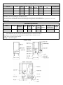
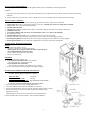
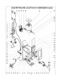
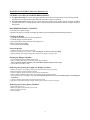
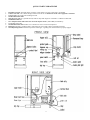
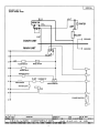
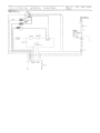
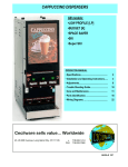
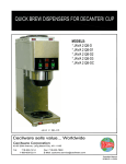
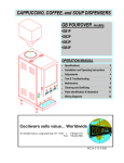
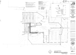
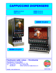
HOT CAPPUCCINO & COFFEE DISPENSER
SERIES
GB1K
OCS-3
OPERATION MANUAL
Specifications
Installation &
Operating instructions
Adjustments
Care & Maintenance
Components Illustration
Parts Identification
Wiring Diagram
Cecilware sells value…Worldwide
th
45-05 20 Avenue, Long Island City, NY 11105
• 718-932-1414
FAX 718-932-7860
NC66A 12W96
Electrical Specifications
60
Kilo
Watts
1.8
Number of
Heaters
1
1
50/60
3.0
1
50/60
3.0
Model No.
Volts
Phase
Hz
GB1K,
120V
1
GB1K
120/240
GB1K
240
15
Receptacle Nema
No.
5-15R
1
15
L14-20R**
20A
1
15
L6-20R*
20A
Amps
Circuit Breaker
15A
120V, 1.8 KW, 15A, Nema 5-15R standard on all models; 3.0 KW, 120/240V units available
** 120/240V, 3 pole, 4 wire grounding type Twist-Plug Receptacle.
For 240V units. Use L6-20R, 2 pole, 3 Wire Twist-Plug Receptacle. For Wiring, refer to Wiring Diagrams.
See Electrical Data Label attached to the back of the unit for proper voltages, breaker sizes and electrical outlet requirements for each model
number listed.
Mechanical Specifications
Model #
# of Hoppers
Hopper Capacity (lb.)
Width
(in.)
Depth
(in.)
Height
(in.)
GB1K-LD
1
8
8.5
20.5
27
Tank
(gal.)
Burst
Capacity
Lit Display Area
(W x H) sq. in
15
(6.75X13.5)91
1.5
Height: Add an additional 4" when installing with 4" legs.
Add an additional 14" min. for water bottle and additional height space to invert bottle over the top.
*Burst Capacities - Max. number of drinks dispensable with available hot water - based on 6 oz. cups.
** Add 2" for line cord and valve fitting clearance.
Plumbing: ¼” water line required.
Ship
Weight
(lb.)
70
INSTALLATION REQUIREMENTS:
This equipment is to be installed to comply with the applicable federal, state, or local plumbing codes having jurisdiction.
In addition:
1. A quick disconnect water connection or enough extra coiled tubing (at least the depth of the unit) so that the machine can be moved for cleaning
underneath.
2. An approved back flow prevention device, such as a double check valve to be installed between the machine and the water supply.
INSTALLATION & PRIMING:
1. Flush inlet water line thoroughly before connecting. If pipe sealant is necessary, Teflon tape is commended.
2. Connect water line to the 1/4" flare fitting located at rear of the unit. A shutoff valve in the water supply line is advisable.
3. Turn on water. Check water line and fittings for leaks.
4. Put HEATER Switch OFF.
5. Plug the power cord into a grounded 120 volt, 60 Hz 15 Amp outlet, Single use. It will take 2 to 4 minutes to fill the tank.
6. Put RINSE Switch ON.
7. Press Dispense Button until water flows out of the dispense nozzle ( 6 to 7 min.). Tank will fill up.
8. PUT RINSE Switch OFF.
9. Put HEATER Switch ON and allow 10 to 15 minutes for water to reach brew temperature.
10. Fill hopper with DRY* powdered product, while waiting for water in tank to heat up. See filling instructions.
11. Push Dispensing Button and check the operation of the hopper. A grinding noise will be heard if not properly engaged.
12. Push Dispensing Button and check drink taste. If adjustments are needed, see "Water Flow Adjustments".
NORMAL DAILY DISPENSER OPERATION
FILLING
1. Open Front Door and lift Top Cover.
2. Fill hopper to desired level with DRY powdered mix.
*Moist product will clog hopper and the unit will not operate properly.
*Never REFRIGERATE powdered product.
Do not overfill or pack product down when filling.
3. Close Top Cover and Door.
DISPENSING
1. Place cup under mixing chamber spout.
2. a) For Manual Units (without Timer): Press and hold
push button until cup is approximately 2/3 full.
b) For Automatic Units (with Timer):
Press and release push button. Cup will fill to size set on Timer.
3. Remove cup when flow from mixing chamber has stopped completely.
WATER FLOW and DRINK STRENGTH ADJUSTMENTS
The unit is factory adjusted to dispense as follows:
Water Flow Rate :
1.2 oz./sec.
Powder/Product Flow Rate:
4 oz./sec.
Corresponding Gram Throw Rate: 4 gr. product per 1.2 oz. of water.
To increase or decrease Drink Strength, proceed as follows:
Remove right hand side Panel of unit. (looking from the front).
Locate Flow Adjustment Key inside unit mounted above water valve.
Engage Flow Adjustment Key into Flow Controller and rotate counterclockwise (CCW) to
decrease and clockwise (CW) to increase drink strength. When making strength
adjustments, do not turn
Adjustment Key more than 1/8" turn at a time without checking drink strength.
4. Return Adjustment Key back into keyholder. If after maximum adjustment.
1.
2.
3.
3
ITEM NO:
DESCRIPTION
1
TANK TOP ASS'Y
2
TANK BAFFLE ASS'Y
3
TANK BAFFLE SEAL
4
TANK CLAMP ASS'Y
5
HEATER ELEMENT 1750W 120V
6
WASHER, FOR HEATER ELEMENT
7
NUT, FOR HEATER ELEMENT
8
TANK WELDMENT ASS'Y
9
ELBOW, MALE 1/8 NPT, WATER INLET FITTING
10
THERMOSTAT
11
HI-LIMIT (TEMPERATURE SAFETY GUARD)
12
DIRECT MOUNTING SEAL / SILICONE FITTING (.461 ID)
13
DRAIN TUBE
14
PLUG, SILICONE , FOR DRAIN HOSE
15
DRAIN HOSE
16
SILICONE HOSE -TANK WATER INLET TO WATER FLOW CONTROL - VALVE
17
SILICONE HOSE -TANK TOP TO DISPENSE GROMMET
18
HOSE BARB FITTING
19
ADJUSTER VALVE ASS'Y #H5107 NPT (ADJUSTMENT KEY INCLUDED)
20
HOSE NUT ASS'Y/ WATER INLET
21
SOLENOID/ WATER INLET VALVE
22
BLOWER DUCT HOSE 16" x (1 " DIA)
23
ELBOW INSERT
24
ELBOW CUP
25
FAN / BLOWER DRYER ASS'Y
26
MOUNTING CLIP (VENT. MOTOR)
27
POWER/ ELECTRICAL CORD
28
TERMINAL BLOCK 120V OR 240V
29
BALLAST
30
RELAY, (NORMALLY OPEN) OR TIMER (OPTIONAL ) 1 20V
31
GB1K FRAME WELDMENT ASS'Y
32
POWER SWITCH (120V) OR (120/240 V)
33
RINSE SWITCH
34
LEGS (SET OF 4)
35
DRIPTRAY PAN metal
36
DRIP TRAY GRILL
37
HEATER INDICATOR LIGHT (amber)
38
HEATER SWITCH, 30A SPST (120V) OR (120/240V)
39
WHIPPER MOTOR short shaft
40
SLINGER DISC
41
CHAMBER MOUNTING GROMMET
42
CHAMBER MOUNT
43
"0" RING # 125 (used w/ grommet)
44
WHIP BLADE
45
EXTENSION TUBE
46
WHIP CHAMBER
47
MIXING CHAMBER
48
DISPENSE CUP
49
"O" RING ((#110) (used w / socket CD67A)
50
MIXING BOWL SOCKET
51
DOOR PLASTIC COVER/PANEL. BLACK
52
DISPENSE BUTTON / SWITCH
53
BRACKET, DOOR SWITCH PANEL
54
STARTER BASE (for lamp inside door)
55
STARTER, TYPE FS - 5, 5-6-8 WATT
56
DOOR HARNESS ASSY
57
BULB, TYPE F8T5/CW
58
LAMP HOLDER
59
300R WELDMENT ASSEMBLY, less components
60
LABEL PANEL, CLEAR
61
PRODUCT GUIDE
62
NYLON AUGER
63
AUGER BUSHING, FRONT
64
HOPPER ASS'Y W/COVER (SQUARE 8 LB)
65
AGITATOR
66
AUGER BUSHING, BACK
67
NUT (FLANGE)
68
SCREW, FOR AUGER MOTOR
69
AUGER MOTOR (90 RPM)
70
SIDE PANELS
* Recommended spare parts
5
PART NUMBERS
QTY
97127
97128
20039
97131
G0140
07059
03051
97293
K330A
59016
59024
M461A
K525A
M391A
M483A
M483A
M550A
K435C
K415A
K178A
L477A
CD 107
CD 108
CD 108
CD56A
RA67A
C035A
B117A OR B116A
CE221
B129A OR 58017
RC85Q
L069A OR L299A
L446A
M172A
RM21Q
RL78A
C002A
L299A
CD75A
CD 126
CD66A
CD65A
M379A
CD64A
M467A
CD63A
CD62A
CD61A
M378A
CD67A
M450A
L455A
RF77A
B128A
L396A
CF19A
CE76A
CE220
RF73Q
M464A
CD70A
CD130
CD102
CD99A
CD141
CD138
CD136
P443A
CD150
R046A
1
1
1
1
1
2
2
1
1
1
1
1
1
1
1
1
1
1
1
1
1
1
1
1
1
1
1
1
1
1
1
1
1
1
1
1
1
1
1
1
1
1
1
1
1
1
1
1
1
1
1
1
1
1
1
1
1
1
2
1
1
1
1
1
1
1
2
1
2
MAINTENANCE INSTRUCTIONS (See Illustration A):
LIT DISPLAY LAMP AND STARTER REPLACEMENT
1. To replace the lamp, first remove the upper inside door panel. Turn the lamp and pull it out of the lamp holder,
then place the new lamp into the lamp holder and turn it until it snaps into position.
2. To replace the starter, remove the upper inside door panel, turn the starter slightly counter-clockwise and take it
out of the starter base. To install the new starter, snap the starter into the starter base and turn it slightly clockwise
into position.
RECOMMENDED DAILY CLEANING
1. Turn the power switch to OFF.
2. Remove the drip tray with grill and empty the contents. Wash with mild dishwasher detergent and dry.
Cleaning the Hopper
1. Open the cabinet door and raise the top cabinet lid.
2. Take the hopper out of the cabinet.
3. Pull off the elbow chute and remove the hopper cover.
4. Rinse each item thoroughly.
5. Dry all items and reassemble.
Filling the Hopper
1. Open the cabinet door, raise the top cabinet lid.
2. Fill the hopper with the correct product. Note: The Hopper can also be removed for filling.
3. Reposition hopper in the hopper compartment, making sure the hopper is properly seated.
Flushing the Whipper Chamber
1. Turn the POWER switch and RINSE switch to ON.
2. Place a container under dispense nozzle and push the Dispense Button.
Note: On manual dispense machines, push and hold the dispense buttons for 10 seconds.
3. Turn the Rinse switch back to OFF.
Removing and Cleaning the Cappuccino Whipper Chamber
1. Remove the dispense cap by pulling it forward and at the same time twisting it clockwise.
2. Pull the mixing bowl out of the mixing bowl socket.
3. Twist the whipping chamber clockwise and pull it off the mounting plate.
4. Pull the Whipper blade off the motor shaft. Notice the flat keyway on the shaft and the
matching keyway inside the Whipper blade shaft. It is important that these two keyways are lined up when re -assembling the
components.
5. Twist the mounting plate clockwise and pull it off the motor shaft.
6. Slip off the o-ring from the Whipper chamber mounting plate and clean o-ring and o-ring seat.
Removing and Cleaning Mixing Chambers
1. Remove the dispense cap.
2. Pull the mixing bowl out of the mixing bowl socket.
3. Take out the extension tubes.
4. Rinse thoroughly.
6
QUICK START-UP PROCEDURE
1.
2.
3.
4.
5.
6.
7.
8.
9.
10.
11.
Flush inlet water line thoroughly before connecting. If pipe sealant is necessary, Teflon tape is commended.
Connect water line to the 1/4" flare fitting located at rear of the unit. A shutoff valve in the water supply line is advisable.
Turn on water. Check water line and fittings for leaks.
Put HEATER Switch OFF.
Plug the power cord into a grounded 120 volt, 60 Hz 15 Amp outlet. Single use. It will take 2 to 4 minutes to fill the tank.
Put RINSE Switch ON.
Pre ss Dispense Button until water flows out of the dispense nozzle ( 6 to 7 min.). Tank will fill up.
PUT RINSE Switch OFF.
Put HEATER Switch ON and allow 10 to 15 minutes for water to reach brew temperature.
Fill hopper with DRY* powdered product, while waiting for water in tank to heat up. See filling instructions.
Push Dispensing Button and check the operation of the hopper. A grinding noise will be heard if not properly engaged.
8