1
ORiNOCO AP-8000
User Guide
AP-8000 User Guide
IMPORTANT!
Proxim recommends you to visit the Proxim Support site at http://
support.proxim.com for Regulatory Information and latest product updates.
Copyright
© 2009 Proxim Wireless Corporation. All rights reserved. Covered by one or more of the following U.S. patents: 5,231,634; 5,875,179;
6,006,090; 5,809,060; 6,075,812; 5,077,753. This User Guide and the software described in it are copyrighted with all rights reserved. No part
of this publication may be reproduced, transmitted, transcribed, stored in a retrieval system, or translated into any language in any form by any
means without the written permission of Proxim Wireless Corporation.
Trademarks
ORiNOCO and Proxim are registered trademarks, and the Proxim logo is a trademark, of Proxim Wireless Corporation.
Acrobat Reader is a registered trademark of Adobe Systems Incorporated.
HyperTerminal is a registered trademark of HilGraeve, Incorporated.
Microsoft and Windows are a registered trademarks of Microsoft Corporation.
Netscape is a registered trademark of Netscape Communications Corporation.
SolarWinds is a registered trademark of SolarWinds.net.
All other trademarks mentioned herein are the property of their respective owners.
GPL License Note
Proxim AP 800/8000 includes software code developed by third parties, including software code subject to the GNU General Public License
("GPL") or GNU Lesser General Public License ("LGPL"). Please see the GPL and LGPL Web sites to view the terms of each license.
To access the GPL Code and LGPL Code used in Proxim AP 800/8000, extract the source version and explore open src directory. The GPL
Code and LGPL Code used in this AP are distributed WITHOUT ANY WARRANTY and are subject to the copyrights of one or more authors.
For details, see the GPL Code and LGPL Code of this AP and the terms of the GPL and LGPL.
OpenSSL License Note
This product contains software developed by the OpenSSL Project for use in the OpenSSL Toolkit (http://www.openssl.org/) and that is subject
to the following copyright and conditions:
Copyright (c) 1998-2002 The OpenSSL Project. All rights reserved.
The names "OpenSSL Toolkit" and "OpenSSL Project" must not be used to refer to, endorse, or promote the products or for any other purpose
related to the products without prior written permission. For written permission, please contact [email protected].
This software is provided by the OpenSSL Project “as is” and any expressed or implied warranties, including, but not limited to, the implied
warranties of merchantability and fitness for a particular purpose are disclaimed. In no event shall the OpenSSL Project or its contributors be
liable for any direct, indirect, incidental, special, exemplary, or consequential damages (including, but not limited to, procurement of substitute
goods or services; loss of use, data, or profits; or business interruption) however caused and on any theory of liability, whether in contract,
strict liability, or tort (including negligence or otherwise) arising in any way out of the use of this software, even if advised of the possibility of
such damage.
ORiNOCO AP-8000 User Guide
Version 1.0.1
P/N 75961, March 2009
2
AP-8000 User Guide
1
Introduction. . . . . . . . . . . . . . . . . . . . . . . . . . . . . . . . . . . . . . . . . . . . . . . . . . . . . . . . . . . . . . . . . . 8
Product Covered in this User Guide . . . . . . . . . . . . . . . . . . . . . . . . . . . . . . . . . . . . . . . . . . . . . . . . . . . . . . . 8
About AP-8000 Dual Radio Wireless Access Point . . . . . . . . . . . . . . . . . . . . . . . . . . . . . . . . . . . . . . . . . . . 8
Core Features of AP-8000 . . . . . . . . . . . . . . . . . . . . . . . . . . . . . . . . . . . . . . . . . . . . . . . . . . . . . . . . . . . . . . 8
Two Independent Multi-Band MIMO Radios . . . . . . . . . . . . . . . . . . . . . . . . . . . . . . . . . . . . . . . . . . . . . . . . . . . . . . 8
802.11n Multiple Input and Multiple Output (MIMO). . . . . . . . . . . . . . . . . . . . . . . . . . . . . . . . . . . . . . . . . . . . . . . . . 9
Security . . . . . . . . . . . . . . . . . . . . . . . . . . . . . . . . . . . . . . . . . . . . . . . . . . . . . . . . . . . . . . . . . . . . . . . . . . . . . . . . . . 9
Quality of Service (QoS) . . . . . . . . . . . . . . . . . . . . . . . . . . . . . . . . . . . . . . . . . . . . . . . . . . . . . . . . . . . . . . . . . . . . . 9
Software Upgrade . . . . . . . . . . . . . . . . . . . . . . . . . . . . . . . . . . . . . . . . . . . . . . . . . . . . . . . . . . . . . . . . . . . . . . . . . . 9
Compliant to Wireless Standards . . . . . . . . . . . . . . . . . . . . . . . . . . . . . . . . . . . . . . . . . . . . . . . . . . . . . . . . . . . . . . . 9
2
Installation and Initialization . . . . . . . . . . . . . . . . . . . . . . . . . . . . . . . . . . . . . . . . . . . . . . . . . . . 10
Hardware Overview . . . . . . . . . . . . . . . . . . . . . . . . . . . . . . . . . . . . . . . . . . . . . . . . . . . . . . . . . . . . . . . . . . 10
LED Indicators . . . . . . . . . . . . . . . . . . . . . . . . . . . . . . . . . . . . . . . . . . . . . . . . . . . . . . . . . . . . . . . . . . . . . . . . . . . . 10
Antennas . . . . . . . . . . . . . . . . . . . . . . . . . . . . . . . . . . . . . . . . . . . . . . . . . . . . . . . . . . . . . . . . . . . . . . . . . . . . . . . . .11
Power Socket . . . . . . . . . . . . . . . . . . . . . . . . . . . . . . . . . . . . . . . . . . . . . . . . . . . . . . . . . . . . . . . . . . . . . . . . . . . . . .11
Reset . . . . . . . . . . . . . . . . . . . . . . . . . . . . . . . . . . . . . . . . . . . . . . . . . . . . . . . . . . . . . . . . . . . . . . . . . . . . . . . . . . . .11
Reload . . . . . . . . . . . . . . . . . . . . . . . . . . . . . . . . . . . . . . . . . . . . . . . . . . . . . . . . . . . . . . . . . . . . . . . . . . . . . . . . . . .11
Ethernet Port . . . . . . . . . . . . . . . . . . . . . . . . . . . . . . . . . . . . . . . . . . . . . . . . . . . . . . . . . . . . . . . . . . . . . . . . . . . . . .11
Serial Port . . . . . . . . . . . . . . . . . . . . . . . . . . . . . . . . . . . . . . . . . . . . . . . . . . . . . . . . . . . . . . . . . . . . . . . . . . . . . . . .11
Description of the AP-8000 Unit. . . . . . . . . . . . . . . . . . . . . . . . . . . . . . . . . . . . . . . . . . . . . . . . . . . . . . . . . . . . . . . 12
Prerequisites . . . . . . . . . . . . . . . . . . . . . . . . . . . . . . . . . . . . . . . . . . . . . . . . . . . . . . . . . . . . . . . . . . . . . . . 12
System Requirements . . . . . . . . . . . . . . . . . . . . . . . . . . . . . . . . . . . . . . . . . . . . . . . . . . . . . . . . . . . . . . . . 13
Product Package . . . . . . . . . . . . . . . . . . . . . . . . . . . . . . . . . . . . . . . . . . . . . . . . . . . . . . . . . . . . . . . . . . . . 13
Optional Accessories . . . . . . . . . . . . . . . . . . . . . . . . . . . . . . . . . . . . . . . . . . . . . . . . . . . . . . . . . . . . . . . . . 14
Hardware Installation . . . . . . . . . . . . . . . . . . . . . . . . . . . . . . . . . . . . . . . . . . . . . . . . . . . . . . . . . . . . . . . . . 14
Attach the Cables. . . . . . . . . . . . . . . . . . . . . . . . . . . . . . . . . . . . . . . . . . . . . . . . . . . . . . . . . . . . . . . . . . . . . . . . . . 14
Using a Console Port . . . . . . . . . . . . . . . . . . . . . . . . . . . . . . . . . . . . . . . . . . . . . . . . . . . . . . . . . . . . . . . . . . . . . . . 15
Install the Cable Security Cover (Optional) . . . . . . . . . . . . . . . . . . . . . . . . . . . . . . . . . . . . . . . . . . . . . . . . . . . . . . 15
Install the Antenna . . . . . . . . . . . . . . . . . . . . . . . . . . . . . . . . . . . . . . . . . . . . . . . . . . . . . . . . . . . . . . . . . . . . . . . . . 15
Mount the Unit . . . . . . . . . . . . . . . . . . . . . . . . . . . . . . . . . . . . . . . . . . . . . . . . . . . . . . . . . . . . . . . . . . . . . . . . . . . . 15
Power on the Unit. . . . . . . . . . . . . . . . . . . . . . . . . . . . . . . . . . . . . . . . . . . . . . . . . . . . . . . . . . . . . . . . . . . . . . . . . . 16
Initialization . . . . . . . . . . . . . . . . . . . . . . . . . . . . . . . . . . . . . . . . . . . . . . . . . . . . . . . . . . . . . . . . . . . . . . . . 18
Using ScanTool . . . . . . . . . . . . . . . . . . . . . . . . . . . . . . . . . . . . . . . . . . . . . . . . . . . . . . . . . . . . . . . . . . . . . . . . . . . 18
Installing the Software . . . . . . . . . . . . . . . . . . . . . . . . . . . . . . . . . . . . . . . . . . . . . . . . . . . . . . . . . . . . . . . . 22
Install Software Using TFTP Server . . . . . . . . . . . . . . . . . . . . . . . . . . . . . . . . . . . . . . . . . . . . . . . . . . . . . . . . . . . . 25
3
Managing the Access Point . . . . . . . . . . . . . . . . . . . . . . . . . . . . . . . . . . . . . . . . . . . . . . . . . . . . 27
HTTP/HTTPS Interface . . . . . . . . . . . . . . . . . . . . . . . . . . . . . . . . . . . . . . . . . . . . . . . . . . . . . . . . . . . . . . . 27
Command Line Interface/Telnet . . . . . . . . . . . . . . . . . . . . . . . . . . . . . . . . . . . . . . . . . . . . . . . . . . . . . . . . . 27
SNMP Management . . . . . . . . . . . . . . . . . . . . . . . . . . . . . . . . . . . . . . . . . . . . . . . . . . . . . . . . . . . . . . . . . . 28
3
AP-8000 User Guide
SSH (Secure Shell) Management . . . . . . . . . . . . . . . . . . . . . . . . . . . . . . . . . . . . . . . . . . . . . . . . . . . . . . . 28
HyperTerminal . . . . . . . . . . . . . . . . . . . . . . . . . . . . . . . . . . . . . . . . . . . . . . . . . . . . . . . . . . . . . . . . . . . . . . 28
ProximVision ES . . . . . . . . . . . . . . . . . . . . . . . . . . . . . . . . . . . . . . . . . . . . . . . . . . . . . . . . . . . . . . . . . . . . 29
4
Basic Configuration for an Enterprise . . . . . . . . . . . . . . . . . . . . . . . . . . . . . . . . . . . . . . . . . . . 30
Configuring Basic Settings for the Access Point . . . . . . . . . . . . . . . . . . . . . . . . . . . . . . . . . . . . . . . . . . . . 30
Finding and Assigning the Access Point’s IP Address . . . . . . . . . . . . . . . . . . . . . . . . . . . . . . . . . . . . . . . . . . . . . . 30
Configuring the System Name and the Country Code . . . . . . . . . . . . . . . . . . . . . . . . . . . . . . . . . . . . . . . . 31
Configuring the Wireless Information . . . . . . . . . . . . . . . . . . . . . . . . . . . . . . . . . . . . . . . . . . . . . . . . . . . . . 31
Configuring the Operational Mode . . . . . . . . . . . . . . . . . . . . . . . . . . . . . . . . . . . . . . . . . . . . . . . . . . . . . . . 31
Password Management . . . . . . . . . . . . . . . . . . . . . . . . . . . . . . . . . . . . . . . . . . . . . . . . . . . . . . . . . . . . . . . 31
Configuring the Security Profile . . . . . . . . . . . . . . . . . . . . . . . . . . . . . . . . . . . . . . . . . . . . . . . . . . . . . . . . . 32
5
Access Point Features . . . . . . . . . . . . . . . . . . . . . . . . . . . . . . . . . . . . . . . . . . . . . . . . . . . . . . . . 34
Configuring the Device . . . . . . . . . . . . . . . . . . . . . . . . . . . . . . . . . . . . . . . . . . . . . . . . . . . . . . . . . . . . . . . . 34
Wireless 11n Properties . . . . . . . . . . . . . . . . . . . . . . . . . . . . . . . . . . . . . . . . . . . . . . . . . . . . . . . . . . . . . . . . . . . . . 34
Ethernet . . . . . . . . . . . . . . . . . . . . . . . . . . . . . . . . . . . . . . . . . . . . . . . . . . . . . . . . . . . . . . . . . . . . . . . . . . . . . . . . . 36
Security . . . . . . . . . . . . . . . . . . . . . . . . . . . . . . . . . . . . . . . . . . . . . . . . . . . . . . . . . . . . . . . . . . . . . . . . . . . . . . . . . 36
RADIUS . . . . . . . . . . . . . . . . . . . . . . . . . . . . . . . . . . . . . . . . . . . . . . . . . . . . . . . . . . . . . . . . . . . . . . . . . . . . . . . . . 39
QoS . . . . . . . . . . . . . . . . . . . . . . . . . . . . . . . . . . . . . . . . . . . . . . . . . . . . . . . . . . . . . . . . . . . . . . . . . . . . . . . . . . . . 42
IP Configuration . . . . . . . . . . . . . . . . . . . . . . . . . . . . . . . . . . . . . . . . . . . . . . . . . . . . . . . . . . . . . . . . . . . . . . . . . . . 43
VLAN . . . . . . . . . . . . . . . . . . . . . . . . . . . . . . . . . . . . . . . . . . . . . . . . . . . . . . . . . . . . . . . . . . . . . . . . . . . . . . . . . . . 44
Filtering . . . . . . . . . . . . . . . . . . . . . . . . . . . . . . . . . . . . . . . . . . . . . . . . . . . . . . . . . . . . . . . . . . . . . . . . . . . . . . . . . 45
Managing the Device . . . . . . . . . . . . . . . . . . . . . . . . . . . . . . . . . . . . . . . . . . . . . . . . . . . . . . . . . . . . . . . . . 48
System Information . . . . . . . . . . . . . . . . . . . . . . . . . . . . . . . . . . . . . . . . . . . . . . . . . . . . . . . . . . . . . . . . . . . . . . . . 48
Upgrading the Firmware. . . . . . . . . . . . . . . . . . . . . . . . . . . . . . . . . . . . . . . . . . . . . . . . . . . . . . . . . . . . . . . . . . . . . 49
Password Management . . . . . . . . . . . . . . . . . . . . . . . . . . . . . . . . . . . . . . . . . . . . . . . . . . . . . . . . . . . . . . . . . . . . . 50
Management Access Control . . . . . . . . . . . . . . . . . . . . . . . . . . . . . . . . . . . . . . . . . . . . . . . . . . . . . . . . . . . . . . . . . 51
Monitoring the Device . . . . . . . . . . . . . . . . . . . . . . . . . . . . . . . . . . . . . . . . . . . . . . . . . . . . . . . . . . . . . . . . 51
System Log . . . . . . . . . . . . . . . . . . . . . . . . . . . . . . . . . . . . . . . . . . . . . . . . . . . . . . . . . . . . . . . . . . . . . . . . . . . . . . 51
Event Log . . . . . . . . . . . . . . . . . . . . . . . . . . . . . . . . . . . . . . . . . . . . . . . . . . . . . . . . . . . . . . . . . . . . . . . . . . . . . . . . 51
SNTP . . . . . . . . . . . . . . . . . . . . . . . . . . . . . . . . . . . . . . . . . . . . . . . . . . . . . . . . . . . . . . . . . . . . . . . . . . . . . . . . . . . 52
Interface Statistics . . . . . . . . . . . . . . . . . . . . . . . . . . . . . . . . . . . . . . . . . . . . . . . . . . . . . . . . . . . . . . . . . . . . . . . . . 52
Bridge. . . . . . . . . . . . . . . . . . . . . . . . . . . . . . . . . . . . . . . . . . . . . . . . . . . . . . . . . . . . . . . . . . . . . . . . . . . . . . . . . . . 53
Network Layer . . . . . . . . . . . . . . . . . . . . . . . . . . . . . . . . . . . . . . . . . . . . . . . . . . . . . . . . . . . . . . . . . . . . . . . . . . . . 54
RADIUS . . . . . . . . . . . . . . . . . . . . . . . . . . . . . . . . . . . . . . . . . . . . . . . . . . . . . . . . . . . . . . . . . . . . . . . . . . . . . . . . . 54
6
Using Web Interface to Manage the Access Point . . . . . . . . . . . . . . . . . . . . . . . . . . . . . . . . . 56
Web Interface Overview . . . . . . . . . . . . . . . . . . . . . . . . . . . . . . . . . . . . . . . . . . . . . . . . . . . . . . . . . . . . . . . 56
Error Message . . . . . . . . . . . . . . . . . . . . . . . . . . . . . . . . . . . . . . . . . . . . . . . . . . . . . . . . . . . . . . . . . . . . . . 56
Configuring the Device . . . . . . . . . . . . . . . . . . . . . . . . . . . . . . . . . . . . . . . . . . . . . . . . . . . . . . . . . . . . . . . . 57
4
AP-8000 User Guide
Wireless . . . . . . . . . . . . . . . . . . . . . . . . . . . . . . . . . . . . . . . . . . . . . . . . . . . . . . . . . . . . . . . . . . . . . . . . . . . . . . . . . 58
Ethernet . . . . . . . . . . . . . . . . . . . . . . . . . . . . . . . . . . . . . . . . . . . . . . . . . . . . . . . . . . . . . . . . . . . . . . . . . . . . . . . . . 63
Security . . . . . . . . . . . . . . . . . . . . . . . . . . . . . . . . . . . . . . . . . . . . . . . . . . . . . . . . . . . . . . . . . . . . . . . . . . . . . . . . . 63
QoS . . . . . . . . . . . . . . . . . . . . . . . . . . . . . . . . . . . . . . . . . . . . . . . . . . . . . . . . . . . . . . . . . . . . . . . . . . . . . . . . . . . . 68
IP Configuration . . . . . . . . . . . . . . . . . . . . . . . . . . . . . . . . . . . . . . . . . . . . . . . . . . . . . . . . . . . . . . . . . . . . . . . . . . . 72
VLAN . . . . . . . . . . . . . . . . . . . . . . . . . . . . . . . . . . . . . . . . . . . . . . . . . . . . . . . . . . . . . . . . . . . . . . . . . . . . . . . . . . . 73
Filtering . . . . . . . . . . . . . . . . . . . . . . . . . . . . . . . . . . . . . . . . . . . . . . . . . . . . . . . . . . . . . . . . . . . . . . . . . . . . . . . . . 73
Managing the Device . . . . . . . . . . . . . . . . . . . . . . . . . . . . . . . . . . . . . . . . . . . . . . . . . . . . . . . . . . . . . . . . . 81
System . . . . . . . . . . . . . . . . . . . . . . . . . . . . . . . . . . . . . . . . . . . . . . . . . . . . . . . . . . . . . . . . . . . . . . . . . . . . . . . . . . 81
System Inventory Management Component . . . . . . . . . . . . . . . . . . . . . . . . . . . . . . . . . . . . . . . . . . . . . . . . . . . . . 82
Upgrading the Firmware. . . . . . . . . . . . . . . . . . . . . . . . . . . . . . . . . . . . . . . . . . . . . . . . . . . . . . . . . . . . . . . . . . . . . 83
Password Management . . . . . . . . . . . . . . . . . . . . . . . . . . . . . . . . . . . . . . . . . . . . . . . . . . . . . . . . . . . . . . . . . . . . . 87
Management Access Control . . . . . . . . . . . . . . . . . . . . . . . . . . . . . . . . . . . . . . . . . . . . . . . . . . . . . . . . . . . . . . . . . 88
Monitoring the Device . . . . . . . . . . . . . . . . . . . . . . . . . . . . . . . . . . . . . . . . . . . . . . . . . . . . . . . . . . . . . . . . 90
System Log . . . . . . . . . . . . . . . . . . . . . . . . . . . . . . . . . . . . . . . . . . . . . . . . . . . . . . . . . . . . . . . . . . . . . . . . . . . . . . 91
Event Log . . . . . . . . . . . . . . . . . . . . . . . . . . . . . . . . . . . . . . . . . . . . . . . . . . . . . . . . . . . . . . . . . . . . . . . . . . . . . . . . 93
SNTP . . . . . . . . . . . . . . . . . . . . . . . . . . . . . . . . . . . . . . . . . . . . . . . . . . . . . . . . . . . . . . . . . . . . . . . . . . . . . . . . . . . 94
Interface Statistics . . . . . . . . . . . . . . . . . . . . . . . . . . . . . . . . . . . . . . . . . . . . . . . . . . . . . . . . . . . . . . . . . . . . . . . . . 95
Bridge. . . . . . . . . . . . . . . . . . . . . . . . . . . . . . . . . . . . . . . . . . . . . . . . . . . . . . . . . . . . . . . . . . . . . . . . . . . . . . . . . . . 98
Network Layer . . . . . . . . . . . . . . . . . . . . . . . . . . . . . . . . . . . . . . . . . . . . . . . . . . . . . . . . . . . . . . . . . . . . . . . . . . . . 99
RADIUS . . . . . . . . . . . . . . . . . . . . . . . . . . . . . . . . . . . . . . . . . . . . . . . . . . . . . . . . . . . . . . . . . . . . . . . . . . . . . . . . 100
7
Using SNMP Interface to Manage the Access Point . . . . . . . . . . . . . . . . . . . . . . . . . . . . . . . 102
Pre-requisites . . . . . . . . . . . . . . . . . . . . . . . . . . . . . . . . . . . . . . . . . . . . . . . . . . . . . . . . . . . . . . . . . . . . . . 102
Viewing the MIB Objects . . . . . . . . . . . . . . . . . . . . . . . . . . . . . . . . . . . . . . . . . . . . . . . . . . . . . . . . . . . . . 102
Configuring the MIB Objects . . . . . . . . . . . . . . . . . . . . . . . . . . . . . . . . . . . . . . . . . . . . . . . . . . . . . . . . . . 103
To Configure the Scalar Objects: . . . . . . . . . . . . . . . . . . . . . . . . . . . . . . . . . . . . . . . . . . . . . . . . . . . . . . . . . . . . . 103
To Configure the Tabular Objects: . . . . . . . . . . . . . . . . . . . . . . . . . . . . . . . . . . . . . . . . . . . . . . . . . . . . . . . . . . . . 103
To apply the changes to the flash memory: . . . . . . . . . . . . . . . . . . . . . . . . . . . . . . . . . . . . . . . . . . . . . . . . . . . . . 103
8
Using CLI to Manage the Access Point . . . . . . . . . . . . . . . . . . . . . . . . . . . . . . . . . . . . . . . . . 104
General Notes on CLI . . . . . . . . . . . . . . . . . . . . . . . . . . . . . . . . . . . . . . . . . . . . . . . . . . . . . . . . . . . . . . . 105
Prerequisite Skills and Knowledge. . . . . . . . . . . . . . . . . . . . . . . . . . . . . . . . . . . . . . . . . . . . . . . . . . . . . . . . . . . . 105
Notation Conventions. . . . . . . . . . . . . . . . . . . . . . . . . . . . . . . . . . . . . . . . . . . . . . . . . . . . . . . . . . . . . . . . . . . . . . 105
Important Terminology . . . . . . . . . . . . . . . . . . . . . . . . . . . . . . . . . . . . . . . . . . . . . . . . . . . . . . . . . . . . . . . . . . . . . 105
Navigation and Special Keys . . . . . . . . . . . . . . . . . . . . . . . . . . . . . . . . . . . . . . . . . . . . . . . . . . . . . . . . . . . . . . . . 106
Messages. . . . . . . . . . . . . . . . . . . . . . . . . . . . . . . . . . . . . . . . . . . . . . . . . . . . . . . . . . . . . . . . . . . . . . . . . . . . . . . 106
Rules for Table Objects . . . . . . . . . . . . . . . . . . . . . . . . . . . . . . . . . . . . . . . . . . . . . . . . . . . . . . . . . . . . . . . . . . . . 107
List Commands . . . . . . . . . . . . . . . . . . . . . . . . . . . . . . . . . . . . . . . . . . . . . . . . . . . . . . . . . . . . . . . . . . . . . . . . . . 107
Command Line Completion . . . . . . . . . . . . . . . . . . . . . . . . . . . . . . . . . . . . . . . . . . . . . . . . . . . . . . . . . . . . . . . . . 107
Command Line Interface Modes Overview . . . . . . . . . . . . . . . . . . . . . . . . . . . . . . . . . . . . . . . . . . . . . . . 108
User Execution Mode. . . . . . . . . . . . . . . . . . . . . . . . . . . . . . . . . . . . . . . . . . . . . . . . . . . . . . . . . . . . . . . . . . . . . . 108
Privileged Mode . . . . . . . . . . . . . . . . . . . . . . . . . . . . . . . . . . . . . . . . . . . . . . . . . . . . . . . . . . . . . . . . . . . . . . . . . . 108
5
AP-8000 User Guide
Accessing the CLI of an Access Point . . . . . . . . . . . . . . . . . . . . . . . . . . . . . . . . . . . . . . . . . . . . . . . . . . . 108
Log into the AP using HyperTerminal. . . . . . . . . . . . . . . . . . . . . . . . . . . . . . . . . . . . . . . . . . . . . . . . . . . . . . . . . . 109
Log into the AP using Telnet . . . . . . . . . . . . . . . . . . . . . . . . . . . . . . . . . . . . . . . . . . . . . . . . . . . . . . . . . . . . . . . . 109
Configuring the Device Using CLI Commands . . . . . . . . . . . . . . . . . . . . . . . . . . . . . . . . . . . . . . . . . . . . . 109
User name and Password Command . . . . . . . . . . . . . . . . . . . . . . . . . . . . . . . . . . . . . . . . . . . . . . . . . . . . . . . . . 109
Show Command Tree Structure Command . . . . . . . . . . . . . . . . . . . . . . . . . . . . . . . . . . . . . . . . . . . . . . . . . . . . . .110
Device Configuration . . . . . . . . . . . . . . . . . . . . . . . . . . . . . . . . . . . . . . . . . . . . . . . . . . . . . . . . . . . . . . . . . . . . . . . 111
Managing the Device Using CLI Commands . . . . . . . . . . . . . . . . . . . . . . . . . . . . . . . . . . . . . . . . . . . . . . 132
Access control and access table configuration . . . . . . . . . . . . . . . . . . . . . . . . . . . . . . . . . . . . . . . . . . . . . . . . . . 132
TFTP Configuration . . . . . . . . . . . . . . . . . . . . . . . . . . . . . . . . . . . . . . . . . . . . . . . . . . . . . . . . . . . . . . . . . . . . . . . 133
Telnet configuration . . . . . . . . . . . . . . . . . . . . . . . . . . . . . . . . . . . . . . . . . . . . . . . . . . . . . . . . . . . . . . . . . . . . . . . 133
HTTP Configuration . . . . . . . . . . . . . . . . . . . . . . . . . . . . . . . . . . . . . . . . . . . . . . . . . . . . . . . . . . . . . . . . . . . . . . . 133
SNMP Read, Read Write Password and Trap Host Table Configuration. . . . . . . . . . . . . . . . . . . . . . . . . . . . . . . 134
System Information Configuration . . . . . . . . . . . . . . . . . . . . . . . . . . . . . . . . . . . . . . . . . . . . . . . . . . . . . . . . . . . . 134
System Management Configuration. . . . . . . . . . . . . . . . . . . . . . . . . . . . . . . . . . . . . . . . . . . . . . . . . . . . . . . . . . . 135
Country Code Configuration. . . . . . . . . . . . . . . . . . . . . . . . . . . . . . . . . . . . . . . . . . . . . . . . . . . . . . . . . . . . . . . . . 136
Inventory management . . . . . . . . . . . . . . . . . . . . . . . . . . . . . . . . . . . . . . . . . . . . . . . . . . . . . . . . . . . . . . . . . . . . 136
Monitoring the Device Using CLI Commands . . . . . . . . . . . . . . . . . . . . . . . . . . . . . . . . . . . . . . . . . . . . . 137
Event Log Configuration. . . . . . . . . . . . . . . . . . . . . . . . . . . . . . . . . . . . . . . . . . . . . . . . . . . . . . . . . . . . . . . . . . . . 137
SNTP Configuration . . . . . . . . . . . . . . . . . . . . . . . . . . . . . . . . . . . . . . . . . . . . . . . . . . . . . . . . . . . . . . . . . . . . . . . 138
Syslog and Hosttable configuration . . . . . . . . . . . . . . . . . . . . . . . . . . . . . . . . . . . . . . . . . . . . . . . . . . . . . . . . . . . 138
Display the INTERFACE Statistics . . . . . . . . . . . . . . . . . . . . . . . . . . . . . . . . . . . . . . . . . . . . . . . . . . . . . . . . . . . . 139
Display the ICMP Statistics . . . . . . . . . . . . . . . . . . . . . . . . . . . . . . . . . . . . . . . . . . . . . . . . . . . . . . . . . . . . . . . . . 141
Display the IPARP Statistics. . . . . . . . . . . . . . . . . . . . . . . . . . . . . . . . . . . . . . . . . . . . . . . . . . . . . . . . . . . . . . . . . 141
Display the WIRELESS Station Statistics. . . . . . . . . . . . . . . . . . . . . . . . . . . . . . . . . . . . . . . . . . . . . . . . . . . . . . . 142
Display the RADIUS Client Authentication Statistics . . . . . . . . . . . . . . . . . . . . . . . . . . . . . . . . . . . . . . . . . . . . . . 143
Display the RADIUS Client Access Statistics. . . . . . . . . . . . . . . . . . . . . . . . . . . . . . . . . . . . . . . . . . . . . . . . . . . . 143
9
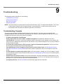
Troubleshooting . . . . . . . . . . . . . . . . . . . . . . . . . . . . . . . . . . . . . . . . . . . . . . . . . . . . . . . . . . . . 144
Troubleshooting Concepts . . . . . . . . . . . . . . . . . . . . . . . . . . . . . . . . . . . . . . . . . . . . . . . . . . . . . . . . . . . . 144
Symptoms and Solutions . . . . . . . . . . . . . . . . . . . . . . . . . . . . . . . . . . . . . . . . . . . . . . . . . . . . . . . . . . . . . 145
Connectivity Issues . . . . . . . . . . . . . . . . . . . . . . . . . . . . . . . . . . . . . . . . . . . . . . . . . . . . . . . . . . . . . . . . . . . . . . . 145
Basic Software Setup and Configuration Problems . . . . . . . . . . . . . . . . . . . . . . . . . . . . . . . . . . . . . . . . . . . . . . . 145
Client Connection Problems. . . . . . . . . . . . . . . . . . . . . . . . . . . . . . . . . . . . . . . . . . . . . . . . . . . . . . . . . . . . . . . . . 147
VLAN Operation Issues . . . . . . . . . . . . . . . . . . . . . . . . . . . . . . . . . . . . . . . . . . . . . . . . . . . . . . . . . . . . . . . . . . . . 147
Gigabit Ethernet PoE . . . . . . . . . . . . . . . . . . . . . . . . . . . . . . . . . . . . . . . . . . . . . . . . . . . . . . . . . . . . . . . . . . . . . . 148
Recovery Procedures . . . . . . . . . . . . . . . . . . . . . . . . . . . . . . . . . . . . . . . . . . . . . . . . . . . . . . . . . . . . . . . . 149
Soft Reset to Factory Defaults . . . . . . . . . . . . . . . . . . . . . . . . . . . . . . . . . . . . . . . . . . . . . . . . . . . . . . . . . . . . . . . 149
Hard Reset to Factory Defaults . . . . . . . . . . . . . . . . . . . . . . . . . . . . . . . . . . . . . . . . . . . . . . . . . . . . . . . . . . . . . . 149
Forced Reload . . . . . . . . . . . . . . . . . . . . . . . . . . . . . . . . . . . . . . . . . . . . . . . . . . . . . . . . . . . . . . . . . . . . . . . . . . . 149
Setting IP Address using Serial Port . . . . . . . . . . . . . . . . . . . . . . . . . . . . . . . . . . . . . . . . . . . . . . . . . . . . . . . . . . 152
Related Applications . . . . . . . . . . . . . . . . . . . . . . . . . . . . . . . . . . . . . . . . . . . . . . . . . . . . . . . . . . . . . . . . 153
6
AP-8000 User Guide
RADIUS Authentication Server . . . . . . . . . . . . . . . . . . . . . . . . . . . . . . . . . . . . . . . . . . . . . . . . . . . . . . . . . . . . . . 153
TFTP Server. . . . . . . . . . . . . . . . . . . . . . . . . . . . . . . . . . . . . . . . . . . . . . . . . . . . . . . . . . . . . . . . . . . . . . . . . . . . . 153
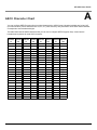
A ASCII Character Chart . . . . . . . . . . . . . . . . . . . . . . . . . . . . . . . . . . . . . . . . . . . . . . . . . . . . . . . 154
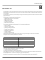
B Bootloader CLI . . . . . . . . . . . . . . . . . . . . . . . . . . . . . . . . . . . . . . . . . . . . . . . . . . . . . . . . . . . . . 155
C Specifications . . . . . . . . . . . . . . . . . . . . . . . . . . . . . . . . . . . . . . . . . . . . . . . . . . . . . . . . . . . . . . 157
Software Specifications . . . . . . . . . . . . . . . . . . . . . . . . . . . . . . . . . . . . . . . . . . . . . . . . . . . . . . . . . . . . . . 157
Number of Stations per BSS . . . . . . . . . . . . . . . . . . . . . . . . . . . . . . . . . . . . . . . . . . . . . . . . . . . . . . . . . . . . . . . . 157
Management Functions . . . . . . . . . . . . . . . . . . . . . . . . . . . . . . . . . . . . . . . . . . . . . . . . . . . . . . . . . . . . . . . . . . . . 157
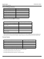
Advanced Bridging Functions . . . . . . . . . . . . . . . . . . . . . . . . . . . . . . . . . . . . . . . . . . . . . . . . . . . . . . . . . . . . . . . 158
Medium Access Control (MAC) Functions . . . . . . . . . . . . . . . . . . . . . . . . . . . . . . . . . . . . . . . . . . . . . . . . . . . . . . 158
Security Features . . . . . . . . . . . . . . . . . . . . . . . . . . . . . . . . . . . . . . . . . . . . . . . . . . . . . . . . . . . . . . . . . . . . . . . . . 158
Network Features. . . . . . . . . . . . . . . . . . . . . . . . . . . . . . . . . . . . . . . . . . . . . . . . . . . . . . . . . . . . . . . . . . . . . . . . . 159
Hardware Specifications . . . . . . . . . . . . . . . . . . . . . . . . . . . . . . . . . . . . . . . . . . . . . . . . . . . . . . . . . . . . . 159
Available Channels . . . . . . . . . . . . . . . . . . . . . . . . . . . . . . . . . . . . . . . . . . . . . . . . . . . . . . . . . . . . . . . . . 160
D Technical Services and Support . . . . . . . . . . . . . . . . . . . . . . . . . . . . . . . . . . . . . . . . . . . . . . . 165
Obtaining Technical Service and Support . . . . . . . . . . . . . . . . . . . . . . . . . . . . . . . . . . . . . . . . . . . . . . . . 165
Support Options . . . . . . . . . . . . . . . . . . . . . . . . . . . . . . . . . . . . . . . . . . . . . . . . . . . . . . . . . . . . . . . . . . . . 166
Proxim eService Web Site Support . . . . . . . . . . . . . . . . . . . . . . . . . . . . . . . . . . . . . . . . . . . . . . . . . . . . . . . . . . . 166
Telephone Support . . . . . . . . . . . . . . . . . . . . . . . . . . . . . . . . . . . . . . . . . . . . . . . . . . . . . . . . . . . . . . . . . . . . . . . . 166
ServPak Support . . . . . . . . . . . . . . . . . . . . . . . . . . . . . . . . . . . . . . . . . . . . . . . . . . . . . . . . . . . . . . . . . . . . . . . . . 166
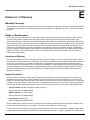
E Statement of Warranty . . . . . . . . . . . . . . . . . . . . . . . . . . . . . . . . . . . . . . . . . . . . . . . . . . . . . . . 168
Warranty Coverage . . . . . . . . . . . . . . . . . . . . . . . . . . . . . . . . . . . . . . . . . . . . . . . . . . . . . . . . . . . . . . . . . 168
Repair or Replacement . . . . . . . . . . . . . . . . . . . . . . . . . . . . . . . . . . . . . . . . . . . . . . . . . . . . . . . . . . . . . . 168
Limitations of Warranty. . . . . . . . . . . . . . . . . . . . . . . . . . . . . . . . . . . . . . . . . . . . . . . . . . . . . . . . . . . . . . . . . . . . . 168
Support Procedures . . . . . . . . . . . . . . . . . . . . . . . . . . . . . . . . . . . . . . . . . . . . . . . . . . . . . . . . . . . . . . . . . . . . . . . 168
Other Information . . . . . . . . . . . . . . . . . . . . . . . . . . . . . . . . . . . . . . . . . . . . . . . . . . . . . . . . . . . . . . . . . . . 169
Search Knowledgebase . . . . . . . . . . . . . . . . . . . . . . . . . . . . . . . . . . . . . . . . . . . . . . . . . . . . . . . . . . . . . . . . . . . . 169
Ask a Question or Open an Issue . . . . . . . . . . . . . . . . . . . . . . . . . . . . . . . . . . . . . . . . . . . . . . . . . . . . . . . . . . . . 169
Other Adapter Cards . . . . . . . . . . . . . . . . . . . . . . . . . . . . . . . . . . . . . . . . . . . . . . . . . . . . . . . . . . . . . . . . . . . . . . 169
7
AP-8000 User Guide
1
Introduction
This chapter contains information on the following:
•
Product Covered in this User Guide
•
About AP-8000 Dual Radio Wireless Access Point
•
Core Features of AP-8000
–
Two Independent Multi-Band MIMO Radios
–
802.11n Multiple Input and Multiple Output (MIMO)
–
Security
–
Quality of Service (QoS)
–
Software Upgrade
–
Compliant to Wireless Standards
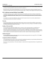
Product Covered in this User Guide
This User Guide details functionality of the following products:
Product
AP-8000
Description
An Access Point with:
•
Two radios that support 2.4GHz/5.0GHz
•
Gigabit Ethernet with PoE support
About AP-8000 Dual Radio Wireless Access Point
The AP-8000 is 802.11n dual radio wireless Access Point that provides connectivity between wired network and wireless
systems and other devices. The AP-8000 wireless Access Point is a Wi-Fi a/b/g/n certified that supports dual radio
modes in 2.4 GHz and 5 GHz frequency band.
With AP-8000, you can achieve higher throughput by increasing the channel width from 20 MHz to 40 MHz thereby
doubling the data rate and by using the MIMO feature. The 802.11n products have incorporated multiple antennas. This
Multiple-Input, Multiple-Output (MIMO) antenna technology provides various features, such as spatial multiplexing, short
Guard Interval (GI) for increased range and throughput.
In AP-8000, using the Channel Bonding technique, you can achieve higher throughput by increasing the channel width
from 20 MHz to 40 MHz thereby doubling the data rate.
NOTE: Wherever “11n” is mentioned, it refers to the Draft 802.11n Version 2.0.
Core Features of AP-8000
Two Independent Multi-Band MIMO Radios
Proxim’s Access Points have two independent multi-band MIMO radios (802.11a/b/g/n) that offer significant increase in
capacity and performance within a given bandwidth and power.
8
Introduction
Core Features of AP-8000
AP-8000 User Guide
The 802.11n Access Points operates on both 2.4 GHz and 5 GHz radio bands. Proxim’s Access Points provides you with
the facility of selecting the band on which you would like to operate on.
Both these radios can be planned independently as per your network requirements. Using the single MAC protocol, it
operates with multiple frequency layers and this improves the range, coverage, and throughput in both frequency bands.
802.11n Multiple Input and Multiple Output (MIMO)
The MIMO technology is used for multiple antennas at both the transmitter and receiver to improve communication
performance. Using the MIMO technology, the Access Points can offer significant increase in data throughput and link
range without additional band width or transmit power. This is achieved by high spectral efficiency and link reliability or
diversity.
For the 802.11n Access Points, MIMO is the heart for the entire system because it uses a third, spatial dimension beyond frequency and time as a carrier of information.
Security
Proxim’s Access Points utilize robust industry-leading security protocols such as WPA and WPA2 to protect sensitive
data that is transmitted over the wireless LAN. You can configure unique security settings for each BSSID according to
your network requirements making it more secure.
Quality of Service (QoS)
The AP supports Wi-Fi Multimedia (WMM), which is a solution for QoS functionality based on the IEEE 802.11e
specification. WMM defines enhancements to the MAC for wireless LAN applications with Quality of Service
requirements, which includes transport of voice and video traffic over IEEE 802.11 wireless LANs. Using this parameter
you can configure the feature that affects the flow of traffic from AP to client station and vice-versa. And also prioritize the
traffic according to your network requirements so that flow of traffic is eased out without loosing any information.
Software Upgrade
You can upgrade the firmware easily as and when you want either through web-GUI, CLI using HTTP or TFTP, SNMP
and ProximVision Element System (PVES).
Compliant to Wireless Standards
The AP-8000 adheres to the 802.11a, 802.11b/g/n draft 2.0 standards that enable you to get the best performance from
your wireless network and support a wide range of compliant devices.
The device can be powered by a 5 VDC power adapter or standard 802.3af compliant fast Ethernet or Gigabit Ethernet
PoE device.
9
AP- 8000 User Guide
Installation and Initialization
2
In this chapter:
•
Hardware Overview
–
LED Indicators
–
Antennas
–
Power Socket
–
Reset
–
Reload
–
Description of the AP-8000 Unit
•
Prerequisites
•
System Requirements
•
Product Package
•
Optional Accessories
•
Hardware Installation
•
–
Attach the Cables
–
Power on the Unit
–
Install the Antenna
–
Initialization
Initialization
–
•
Using ScanTool
Installing the Software
–
Install Software Using TFTP Server
Hardware Overview
The Access Point supports dual radio operations using the 2.4 GHz and 5 GHz, and has six antenna connectors. The
Access Point support dual radio operation using 2.4 GHz and 5 GHz. It contains two 802.11a/b/g/n radios that can
operate independently on 2.4 GHz and 5 GHz. It contains 6 antennas, 3 for each radio.
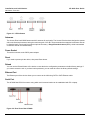
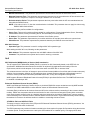
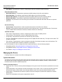
LED Indicators
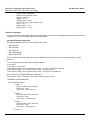
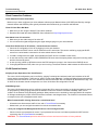
The top panel of the AP-8000 has the following LED indicators:
•
The Power LED provides whether the device is switched on/off.
•
The Ethernet LED signals Ethernet traffic on the wired Ethernet LAN
•
The Wireless Interface (Radio)1 LED provides the status and the speed on the wired Ethernet LAN.
•
The Wireless Interface (Radio)2 LED provides the status of the wireless radio.
10
Installation and Initialization
Hardware Overview
AP-8000 User Guide
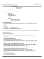
Figure 2-1 LED Indicators
Antennas
The Access Point has 6 MIMO antennas with 3 antennas for each radio. The Access Point has been designed to operate
with omni-directional antennas, having the maximum gain of 2.5 dBi. These antennas have standard connectors and can
be installed easily. Proxim also provides an optional accessory - Range Extender Antenna (REA), which has standard
connectors and can be installed easily.
Power Socket
This socket connects to the 5VDC power adapter.
Reset
If you need to powercycle the device, then press Reset button.
Reload
You can use the Reload feature of the device to reset the device configuration parameters to default factory settings. If
you cannot access the unit or you have lost its password, you can reset the unit to the factory default settings.
Ethernet Port
The Ethernet port of the device allows you to connect to the LAN using CAT5 or CAT6 Ethernet cable.
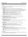
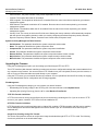
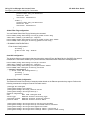
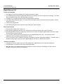
Serial Port
The AP-8000 has RS-232 connector using which serial communication can be established with PC or laptop.
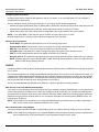
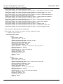
Figure 2-2 Rear View of the AP-8000
11
Installation and Initialization
Prerequisites
AP-8000 User Guide
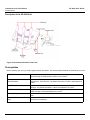
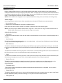
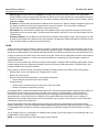
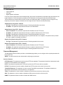
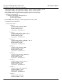
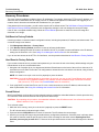
Description of the AP-8000 Unit
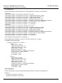
Figure 2-3 Schematic Illustration of the Unit
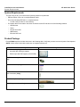
Prerequisites
Before installing your unit, you need to gather certain information. The following table identifies the information you need:
AP’s IP Address
If you do not have a DHCP server on your network, then you need to assign the
Access Point an IP address that is valid on your network.
Web Interface/Telnet/CLI User
Name/Password
Each Access Point requires a read/write username and password to access the
web interface, Telnet and CLI. The default username is “admin” and password is
“public”.
SNMP Read Password
Each Access Point requires a password to allow get requests from an SNMP
manager. The default username is “admin” and password is “public”.
SNMP Read-Write Password
Each Access Point requires a password to allow get and set requests from an
SNMP manager. The default password is “public”.
Security Settings
You need to determine what security features you will enable on the Access
Point.
Gateway IP Address and Subnet
Mask
The gateway IP address and subnet mask of the network environment where the
Access Point is deployed.
12
Installation and Initialization
System Requirements
AP-8000 User Guide
System Requirements
To begin using an AP, you must have the following minimum requirements:
•
Ethernet switch, cross-over or straight Ethernet cable.
•
One of the following IEEE 802.11- compliant devices:
–
•
An 802.11a/b/g or 802.11n client devices
A computer that is connected to the same IP network as the AP and has one of the following installed:
–
Web Browser
–
Telnet
–
RS-232 Serial Port
–
MIB Browser
–
Ethernet NIC Card
Product Package
Each AP-8000 shipment includes the items in the following table. Verify that you have received all parts of the shipment.
NOTE: Unless noted in this table, cables are not supplied with the unit.
AP-8000 Product Package Description
Images
AP-8000 unit with (1 Qty):
– two radio (802.11a/b/g/n) support
– Ethernet port with PoE support (10/100/1000)
CD-ROM containing software and documentation (1
Qty)
Quick Install Guide (1 Qty)
2.4 GHz/ 5GHz omni-directional antennas with reverse
SMA connectors (6 Qty)
Cable Security Cover (1 Qty)
Wall/Ceiling mount plate (1 Qty)
13
Installation and Initialization
Optional Accessories
AP-8000 User Guide
Optional Accessories
You can also use these optional accessories that Proxim recommends.
110-220V worldwide power adapter (1 Qty)
Range Extender Antenna (REA)
Gigabit Ethernet PoE
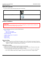
Hardware Installation
IMPORTANT:
Before installing and using this product, see Safety and Regulatory Compliance Guide available with
AP-8000 Answer ID 2814 at http://support.proxim.com.
Perform the following procedures to install the AP-8000 hardware:
•
Attach the Cables
–
Cabling with Power Adapter
–
Cabling with Gigabit Ethernet PoE
•
Using a Console Port
•
Install the Cable Security Cover (Optional)
•
Install the Antenna
•
Mount the Unit
•
Power on the Unit
Attach the Cables
NOTE: Proxim recommends to use CAT6 cable for the length of 100 m or CAT5e cable for lower length. Though the
AP-8000 can work with CAT5 cable, there is a possibility that you may experience a drop in Ethernet speed from
1000BaseT to 100BaseT or Ethernet interface may show errors.
Cabling with Power Adapter
1. Plug the barrel of the power cable from the power supply into the power jack.
2. Connect one end of an CAT 6 Ethernet cable (not supplied) to the unit’s Ethernet port. The other end of the cable
should not be connected to another device until installation is complete:
•
Use a straight-through CAT 6 Ethernet cable if you intend to connect the unit to a switch, hub, or patch panel.
•
Use a cross-over Ethernet cable CAT6) or adapter if you intend to connect the unit to a single computer.
14
Installation and Initialization
Hardware Installation
AP-8000 User Guide
Cabling with Gigabit Ethernet PoE
1. To power the device using Gigabit Ethernet PoE, you must use Gigabit PoE injector (ordered separately). Connect
one end of a CAT6 Ethernet cable (not supplied) to the unit’s Ethernet port. Connect the other end to the Data and
Power Out port of the PoE Injector.
2. Connect one end of the second CAT6 Ethernet cable to the Data In port of the DC Injector. The other end of the cable
should not be connected to another device until installation is complete:
•
Use a straight-through cable if you intend to connect the unit to a switch, hub or patch panel.
•
Use a cross-over Ethernet cable (CAT6) or adapter if you intend to connect the unit to a single computer.
Using a Console Port
You may connect your Access Point with a console port. Follow the steps provided below if you are using the Console
port:
1. Connect a nine-pin, male-to-female serial cable to the COM port on a computer or laptop and to the DB9 connector of
the Access Point.
2. Open the Microsoft’s HyperTerminal to set up the AP-8000. For more information refer Initialization.
Install the Cable Security Cover (Optional)
When the RS-232 cable is not connected, you may install a security cover to deter unauthorized access to the unit. The
security cover is a plastic enclosure that prevents access to the power and LAN ports, and the Reset and Reload
buttons.
1. Open the split end of the security cover just enough to slide the power cable (if you are not using Gigabit Ethernet
PoE) and the CAT 6 Ethernet cable through the opening until they fit inside the straight clamping portion of the cover.
Exercise care as you slide the cable (s) so you do not accidentally break the cover.
2. Slide the hinging end of the security cover into the hole on the rear panel of the unit to the left of connectors. Once in
place, pivot the cover to bring it close to the rear panel of the unit.
3. Use two screws to fasten the security cover on to the rear panel of the unit.
Install the Antenna
The omni-directional antennas supplied with the product do not require any professional installation as they have
non-standard connectors.
NOTE: Optionally, you can use the Range extended Antenna (REA). This accessory also has non-standard connectors,
and can install them easily.
If the regular outdoor antennas are used, connected via a pigtail conversion cable that offers a standard connector type
for antenna connection, then professional installation is required.
Follow these steps to assemble the antennas to AP-8000:
1. Hand-tighten the antennas clockwise, onto the outer connectors of AP-8000 until they are firmly attached.
2. Position the antennas as close to the horizontal surface (ceiling or wall), so as to get the maximum signal coverage of
the omni-directional antenna.
NOTE: Proxim recommends to aim the antenna horizontal, as the wireless coverage angle is wider with the antenna
pointing up or down.
Mount the Unit
Proxim recommends that you have site survey professionally conducted to determine the best location for the AP.
The following considerations must be kept in mind when the AP-8000 is mounted.
15
Installation and Initialization
Hardware Installation
AP-8000 User Guide
•
The AP must be protected from exposure, and the environmental conditions must be within those specified in the
product datasheet that can be found at http://www.proxim.com/products/
•
The AP-8000 uses +5V/3.5A power adapter.
•
Note that the AP-8000 has been certified under UL Standard 2043 and can be installed in the plenum. In an office
building, plenum is the space between the structural ceiling and the tile ceiling that is provided to help air circulate.
Many companies also use the plenum to house communication equipment and cables. These products and cables
must comply with certain safety requirements, such as Underwriter Labs (UL) and Standard 2043: “Standards for Fire
Test for Heat and Visible Smoke Release for Direct Products and Their Accessories installed in Air-Handling Spaces”.
NOTE: When installed in a plenum, the AP must use PoE.
Once you have chosen a final location for your unit, the following are the mounting options are available:
•
Wall Mounting
•
Ceiling Mounting
Wall Mounting
Follow these steps to mount the unit on a wall:
1. If the unit’s power supply is plugged in, unplug it.
2. Put the mounting plate up to the wall so that the embossed letter “L” is on the top. If the plate is correctly oriented, the
circular tab that is vertically aligned with the square hole should be on top.
3. Fasten the mounting plate with two screws through the circular holes of the plate. Depending on the type of wall, you
may need to use the fasteners.
4. Holding the unit so that the connectors on the rear, align the holes on the bottom of the unit with the two tabs on the
mounting plate. Press the unit down so it is flush with the plate.
5. Carefully slide the unit to the up until the tabs snap securely on to the narrow holes of the unit. if the unit is mounted
correctly, no portion of the mounting plate should protrude from any of the sides of the unit.
Ceiling Mounting
Follow these steps to mount the unit to a ceiling:
1. If the unit’s power supply is plugged in, unplug it.
2. Snap the rectangular tabs on the back of the mounting plate onto a ceiling T-bar. You may need to slightly rotate the
plate until it securely snaps onto the T-bar.
3. Fasten the mounting plate to the ceiling tile with two screws through the circular holes of the plate.
4. Position so that the embossed letter “L” on the mounting plate is facing up. Hold the unit so that the connectors on the
rear, align the two holes on the bottom of the unit with the two tabs on the mounting plate. Press the unit up so it is
flush with the plate.
5. Carefully slide the unit to the “L” direction until the tabs snap securely onto the narrow holes of the unit. If the unit is
mounted correctly, no portion of the mounting plate should protrude from any of the sides of the unit.
Power on the Unit
The AP can be powered by a power supply (just plug the power cord of the power supply into an AC power outlet), or by
Gigabit Ethernet PoE.
When power is applied to the Access Point, you will observe that Power LED lights up Green.
Connect the AP-8000 Ethernet port to a stand-alone PC using Ethernet cable, or to a network hub or switch. You can
monitor the Ethernet LEDs on the top of the Access Point. The color of the Ethernet LEDs will inform about the speed of
the Ethernet traffic:
•
GREEN: 1000 Mbps
16
Installation and Initialization
Hardware Installation
•
RED: 100 Mbps
•
BLANK: No link available or Ethernet is not connected
AP-8000 User Guide
NOTE: When in operational status, the wireless LEDs will be steady Green. The wireless LEDs would blink Green when
the wireless traffic is being transmitted or received.
17
Installation and Initialization
Initialization
AP-8000 User Guide
Initialization
The following sections detail how to initialize the AP using the ScanTool, log in to the HTTP interface, perform an initial
configuration if required (the Access Points are configured to a default settings) and download the required AP software.
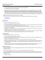
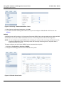
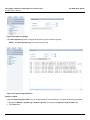
Using ScanTool
ScanTool is a software utility that is included in the installation CD-ROM. It is an initial configuration tool that allows you to
find the IP address of an Access Point by referencing the MAC address in a Scan List, or to assign an IP address if one
has not been assigned.
The tool automatically detects the Access Points installed in your network, regardless of IP address, and lets you
configure each unit’s IP settings. In addition, you can use set initial device parameters that will allows the AP to retrieve
new software to an AP that does not have a valid software image installed.
To access the HTTP interface and configure the AP, the AP must be assigned an IP address that is valid on its Ethernet
network. By default, the AP is configured to obtain an IP address automatically from the network Dynamic Host
Configuration Protocol (DHCP) server during the boot-up.
If your network contains a DHCP server, you can run the ScanTool to find out what IP address the AP has been
assigned.
If your network does not contain a DHCP server, the Access Point’s IP address defaults to 169.254.128.132 and the
device starts with a dynamic IP address. By default, the IP address is Static.
ScanTool Instructions
Follow these steps to install ScanTool and initialize the AP:
1. Power up, reboot, or reset the AP.
2. Double-click the ScanTool icon on the Windows desktop to launch the program (if the program is not already running).
If the icon is not on your desktop, click Start > All Programs > ORiNOCO > AP-8000 > Xtras > ScanTool.
NOTE: If your computer has more than one network adapter installed, you will be prompted to select the adapter that
you want ScanTool to use before the Scan List appears. You can use either an Ethernet or wireless adaptor. If
prompted, select an adapter and click OK. You can change your adapter setting at any time by clicking the Select
Adapter button on the Scan List screen.
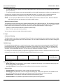
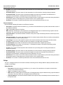
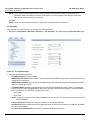
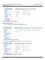
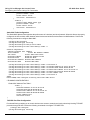
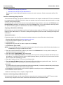
ScanTool scans the subnet and displays all detected Access Points. The ScanTool’s Scan List screen appears, as
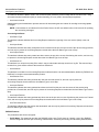
shown
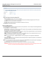
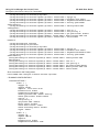
Figure 2-4 ScanTool
3. Locate the MAC address of the AP you want to initialize within the Scan List.
18
Installation and Initialization
Initialization
AP-8000 User Guide
NOTE: If your Access Point does not appear in the Scan List, click the Rescan button to update the display. If the unit still
does not appear in the list, see Troubleshooting for suggestions. Note that after rebooting an Access Point, it
may take up to five minutes for the unit to appear in the Scan List.
4. Do one of the following:
•
If the AP has been assigned an IP address by a DHCP server on the network:
a. Highlight the entry for the AP you want to configure.
b. Click the Change button. The Change screen appears.
c. Click on the Web Configuration button at the bottom of the change screen.
d. Proceed to the Logging In section for information on how to access the HTTP interface using the IP address.
•
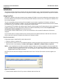
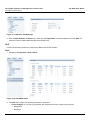
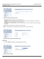
If the AP has not been assigned an IP address (in other words, the unit is using its default IP address,
169.254.128.132), follow these steps to assign it a static IP address that is valid on your network:
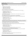
a. Highlighting the entry for the AP you want to configure.
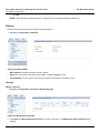
b. Click the Change button. The Change screen appears.
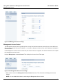
Figure 2-5 Change Screen
c. Set IP Address Type to Static.
d. Enter a static IP Address for the AP in the field provided. You must assign the unit a unique address that is
valid on your IP subnet. Contact your network administrator if you need assistance selecting an IP address for
the unit.
e. Enter your network’s Subnet Mask.
f.
Enter your network’s Gateway IP Address.
g. Enter the SNMP Read/Write password in the Read/Write Password field (for new units, the default SNMP
Read/Write password is public).
NOTE: The TFTP Server IP Address and Image File Name fields are only available if ScanTool detects that the AP does
not have a valid software image installed.
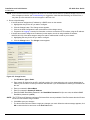
h. Click OK to save your changes.
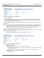
i.
The Access Point will need reboot to apply any changes you made. When the reboot message appears, click
OK to reboot the device and return to the Scan List screen.
19
Installation and Initialization
Initialization
AP-8000 User Guide
Figure 2-6 Change Screen - Reboot
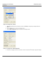
j.
After allowing sufficient time for the device to reboot, click Rescan to verify that your changes have been
applied.
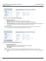
k. Click the Change button to return to the Change screen.
l.
Click the Web Configuration button at the bottom of the Change screen.
Figure 2-7 Change Screen - Web Configuration
m. Proceed to the Logging In section for information on how to access the HTTP interface using this IP address.
20
Installation and Initialization
Initialization
AP-8000 User Guide
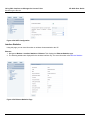
Logging In
Once the AP has a valid IP Address and an Ethernet connection, you may use your web browser to monitor and
configure the AP. (To configure and monitor using the command line interface, see Using CLI to Manage the Access
Point and To configure and monitor using the SNMP interface, see Using SNMP Interface to Manage the Access Point.)
1. Open a Web browser on a network computer.
2. If necessary, disable the browser’s Internet proxy settings. For Internet Explorer users, follow these steps:
–
Select Tools > Internet Options.
–
Click the Connections tab.
–
Click LAN Settings.
–
If necessary, remove the check mark from the Use a proxy server box.
–
Click OK twice to save your changes and return to Internet Explorer.
3. Enter the Access Point’s IP address in the browser’s Address field and press Enter or Go.
This is either the dynamic IP address assigned by a network DHCP server or the static IP address you manually
configured. See Using ScanTool for information on how to determine the unit’s IP address and manually configure a
new IP address, if necessary.
The Access Point Login screen appears.
Figure 2-8 Login
4. Enter the HTTP User Name and Password. The default username and password are “admin” and “public”. The user
name and password are case-sensitive fields.
NOTE: The Home Page is automatically launched. By default, the Access Point is configured to the default settings
and with those settings you can manage your access point. You can make changes/modify the default
settings according to your network requirements.
The links on the left of the screen provide access to the configuration, management and monitoring options for the AP.
The Command Line Interface (CLI) also provides a method for monitoring and configuring the AP using Telnet or a serial
connection. For more information about monitoring and configuring the AP with the CLI, see Using CLI to Manage the
Access Point.
Using SNMP Interface you can configure and monitor the AP, see Using SNMP Interface to Manage the Access Point
21
Installation and Initialization
Installing the Software
AP-8000 User Guide
Installing the Software
Proxim periodically releases updated software for the AP on its Web site, Check the Web site for the latest updates after
you have installed and initialized the unit.
1. In your web browser, go to http://support.proxim.com
2. If prompted, create an account to gain access.
NOTE: The Knowledge base is available to all website visitors. First -time users will be asked to create an account to
gain access.
3. Click Search Knowledgebase.
4. In the Search Knowledgebase field, enter 2814 for AP-8000.
5. Click Search.
6. Click on the appropriate link to access the download page.
7. Use the instructions in the following sections to install the new software.
Use the File Management to upload or download the latest AP software files (images, config etc) from host device to the
device or device to host device.
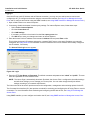
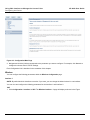
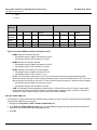
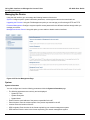
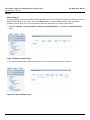
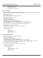
Update Device Using HTTP
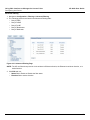
Use the HTTP Download page to download config, image files to the device. In the HTTP Download page, perform the
following procedure to download the specific file:
Figure 2-9 Update Device using the HTTP Download Page
1. Select the File Type that needs to be updated from the drop-down box. Choices include:
–
Image for the AP Image (executable program).
–
Config for configuration, such as System Name, Contact Name and so on.
2. Use the Browse button or manually type in the name of the file to be downloaded (including the file extension in the
File Name field. If typing the file name, you must include the full path and the file extension in the file name text box.
3. To initiate the HTTP Update operation, click Update button.
NOTE: An HTTP file transfer using SSL may take extra time.
•
If the operation is completed successfully the device would provide the information about the successful update.
Figure 2-10 Update Device Using HTTP- Success Message
22
Installation and Initialization
Installing the Software
•
AP-8000 User Guide
If the operation is not completed successfully the following screen appears, and the reason for the failure is
displayed.
Figure 2-11 Update Device Using HTTP- Failure Message
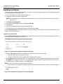
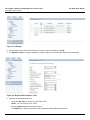
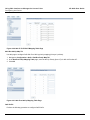
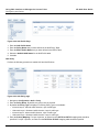
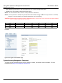
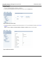
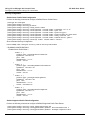
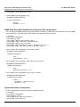
Update Device Using TFTP
Use the TFTP Download page to download config, image file to the device. A TFTP server must be running and
configured to pint to the directory containing the file.
If you do not have a TFTP server installed on your system, install the TFTP server from the installation CD. You can
either install the TFTP server from the CD Wizard or run OEM-TFTP-Server.exe found in the CD’s Xtras/SolarWinds
sub-directory.
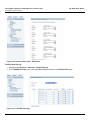
Using the TFTP Download page to enter the following information as described below:
Figure 2-12 Update Device Using TFTP Server
•
Server IP Address: Enter the TFTP server IP Address.
–
Double-click the TFTP server icon on your desktop and locate the IP address assigned to the TFTP server.
NOTE: This is the IP address that will be used to point the Access Point to the AP Image file.
•
File Name: Enter the name of the file to be downloaded (including the file extension).
–
•
•
Copy the file to the TFTP server’s root folder.
File Type: Select the proper file type. Choices include:
–
Config: Configuration information, such as System name, contact name, and so on.
–
Image: AP image (executable program)
Operation: Select either Download or Download & Reboot. You should reboot the AP after downloading files.
NOTE: If you select None as Operation, then no operation will be performed.
Click OK to initiate the process.
•
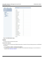
If the operation is completed successfully the device would provide the information about the successful update.
23
Installation and Initialization
Installing the Software
AP-8000 User Guide
Figure 2-13 Update Device Using TFTP- Success Message
•
If the operation is not completed successfully the following screen appears, and the reason for the failure is
displayed.
Figure 2-14 Update Device Using TFTP- Failure Message
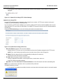
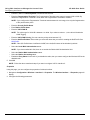
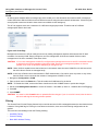
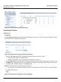
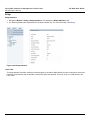
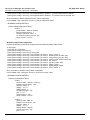
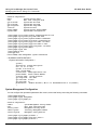
Retrieve From Device Using HTTP
Use the HTTP Upload page to retrieve config files from device.
1. Select the type of file (config, event log) from the File Type drop-down box.
2. Click Retrieve button to initiate the process.
Figure 2-15 Retrieve File using HTTP
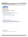
3. The Download page is displayed. Click Download to download the file.
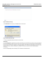
Figure 2-16 Download Page
4. File Download window pops up. Click Save button to save the file.
24
Installation and Initialization
Installing the Software
AP-8000 User Guide
Figure 2-17 File Download Page
5. Select an appropriate filename and location and click Save.
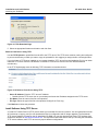
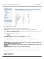
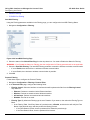
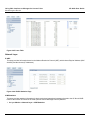
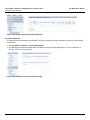
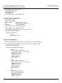
Retrieve From Device Using TFTP
Use the TFTP Upload to upload files from the AP to the TFTP server. The TFTP server must be running and configured
to point to the directory to which you want to copy the uploaded file. We suggest you assign the file a meaningful name.
If you don’t have a TFTP server installed on your system, install the TFTP server from the installation CD. You can either
install the TFTP server from the CD Wizard or run OEM-TFTP-Server.exe found in the CD’s Xtras/SolarWinds
sub-directory.
In the TFTP Upload page enter the following TFTP information as described below:
Figure 2-18 Retrieve From Device Using TFTP
•
Server IP Address: Enter the TFTP server IP Address.
–
Double-click the TFTP server icon on your desktop and locate the IP address assigned to the TFTP server.
•
File Name: Enter the name of the file to be uploaded.
•
File Type: Select the type of the file to be uploaded: Config file or Event Log.
Click Retrieve to initiate the procedure.
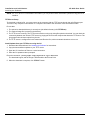
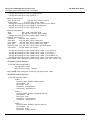
Install Software Using TFTP Server
A Trivial File Transfer Protocol (TFTP) server allows you to transfer files across a network. You can upload files from the
AP for backup or copying, and you can download the files for configuration and AP Image upgrades. The Solarwinds
TFTP server software is located on the AP Installation CD-ROM. You can also download the latest TFTP software from
Solarwind’s Web site at http://www.solarwinds.net. The instructions that follow assume that you are using the Solarwinds
TFTP server software; other TFTP servers may require different configurations.
25
Installation and Initialization
Installing the Software
AP-8000 User Guide
NOTE: If a TFTP server is not available in the network, you can perform similar file transfer operations using the HTTP
interface.
TFTP Server Setup
To download or upload a file, you must connect to the computer with the TFTP server through the unit’s Ethernet port.
This can be any computer in the network or a computer connected to the unit with a cross-over Ethernet cable.
Ensure that:
1. The upload or download directory is correctly set (the default directory is C:\TFTP-Root).
2. The required image file is present in the directory.
3. The TFTP server is running. The TFTP server must be running only during file upload or download. You can check the
connectivity between the unit and TFTP server by pinging the unit from the computer that hosts the TFTP server. The
ping program should show replies from the unit.
4. The TFTP server is configured to both Transmit and Receive files, with no automatic shutdown or time-out.
Install Updates from your TFTP Server using the CLI
1. Download the latest software. See Installing the Software for instructions.
2. Copy the latest software updates to your TFTP server.
3. Open the CLI interface via Telnet or a serial connection.
4. Enter the CLI password when prompted.
Enter the command: (config-mgmt-tftp)#operation-type download
The download begins, and the image is downloaded to the Access Point.
5. When the download is complete, click REBOOT button.
26
AP-8000 User Guide
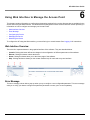
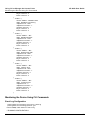
Managing the Access Point
3
There are several management and monitoring interfaces available to the network administrator to configure and
manage an AP on the network:
•
HTTP/HTTPS Interface
•
Command Line Interface/Telnet
•
SNMP Management
•
SSH (Secure Shell) Management
•
ProximVision ES
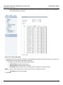
HTTP/HTTPS Interface
The HTTP Interface (Web browser Interface) provides easy access to configuration settings and network statistics from
any computer on the network. You can access the HTTP Interface over your LAN (switch, hub, etc.), over the Internet, or
with a “crossover” Ethernet cable connected directly to your computer’s Ethernet Port.
HTTPS provides an HTTP connection over a Secure Socket Layer. HTTPS is one of the three available secure
management options on the AP; the other secure management option is SSH. HTTPS allows the user to access the AP
in a secure fashion using Secure Socket Layer (SSL) over port 443. The AP supports SSLv3 with a 128-bit encryption
certificate maintained by the AP for secure communications between the AP and the HTTP client. All communications
are encrypted using the server and the client-side certificate.
NOTE: When the AP is powered on, it always comes up with the default IP Address 169.254.128.132 for the first time,
unless otherwise it is configured to use a different IP, or send request to a dynamic server. In other words, the
default ip address type is "static".
•
If the DHCP server is available, then AP-800 unit will be assigned an IP address automatically. You can find the IP
address of the device either from the DHCP server or the ScanTool.
•
If the DHCP server is not available, then you can use the default IP address (169.254.128.132) or change the IP
address of your subnet using the ScanTool. You can log in to the device using the default UserName (admin) and
Password (public).
NOTE: The UserName and Password are case-sensitive.
The AP comes pre-installed with all required SSL files: default certificate, private key and SSL Certificate Pass-phrase
installed.
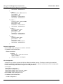
Command Line Interface/Telnet
The Command Line Interface (CLI) is a text-based configuration utility that supports a set of keyboard commands and
parameters to configure and manage an AP. To login to the CLI Interface, follow the procedure:
1. Confirm that your computer’s IP address is same as that of the IP subnet of the AP.
2. Go to the DOS Command prompt on your computer.
3. Type telnet <IP address of the unit>.
4. Enter the User Name and Password. The default username is “admin” and the default password is “public”. The
username and password are case-sensitive.
5. From here proceed further to configure the device interface.
You can enter Command Statements, composed of CLI Commands and their associated parameters. Statements may
be issued from the keyboard for real time control, or from scripts that automate configuration.
27
Managing the Access Point
SNMP Management
AP-8000 User Guide
For example, when downloading a file, administrators enter the download CLI Command along with IP Address, file
name, and file type parameters.
You can access the CLI over a HyperTerminal serial connection or via Telnet. During initial configuration, you can use the
CLI over a serial port connection to configure an Access Point’s IP address. When accessing the CLI via Telnet, you can
communicate with the Access Point from over your LAN (switch, hub, etc.), from over the Internet, or with a “crossover”
Ethernet cable connected directly to your computer’s Ethernet Port. See Using CLI to Manage the Access Point for more
information on the CLI and for a list of CLI commands and parameters.
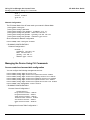
SNMP Management
In addition to the HTTP and the CLI interfaces, you can also manage and configure an AP using the Simple Network
Management Protocol (SNMP). Note that this requires an SNMP manager program. The AP supports following
Management Information Base (MIB) files that describe the parameters that can be viewed and/or configured over
SNMP:
•
MIB-II (RFC 1213)
•
Proxim Enterprise MIB
Proxim provides these MIB files on its support site http://support.proxim.com. You need to logon to the support site and
use the Answer ID: 2814 to locate the MIB. You need to compile one or more of the above MIBs into your SNMP
program’s database before you can manage an Access Point using SNMP.
The Enterprise MIB defines the read and read-write objects that can be viewed or configured using SNMP. These objects
correspond to most of the settings and statistics that are available with the other management interfaces. See the
Enterprise MIB for more information; the MIB can be opened with any text editor, such as Microsoft Word, Notepad, or
WordPad.
SSH (Secure Shell) Management
You may securely also manage the AP using SSH (Secure Shell). The AP supports SSH version 2, for secure remote CLI
(Telnet) sessions. SSH provides strong authentication and encryption of session data.
The SSH server (AP) has host keys - a pair of asymmetric keys - a private key that resides on the AP and a public key
that is distributed to clients that need to connect to the AP. As the client has knowledge of the server host keys, the client
can verify that it is communicating with the correct SSH server.
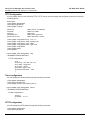
HyperTerminal
HyperTerminal is a program that you can use to connect to other computers, Telnet sites, and bulletin board systems
(BBSs), online services, and host computers, using either your modem or a null modem cable.
•
If you are using RS-232 cable, verify the following information in the Hyper Terminal Serial Port Setup:
Port
COM1 (default)
Baud Rate
115200
Data
8-bit
Parity
None
Stop
1-bit
Flow Content
NONE
28
Managing the Access Point
ProximVision ES
•
AP-8000 User Guide
Log in to the device using the default User Name as “admin” and Password as “public”. The username and
password are case sensitive. The Home page displays.
NOTE: The User Name and Password are case-sensitive
ProximVision ES
Using ProximVision ES you can discover and manage your AP-800 device. For more information, refer to the PVES User
Guide.
29
AP-8000 User Guide
Basic Configuration for an Enterprise
4
This chapter describes the initial configuration of the Access Point using the web-browser. By default, the pre-configured
Access Point can be accessed, but as an enterprise user, you can modify the default settings of the Access Point to
provide a secure access for your enterprise.
In this chapter, following sections are included:
•
Configuring Basic Settings for the Access Point
–
Finding and Assigning the Access Point’s IP Address
•
Configuring the System Name and the Country Code
•
Configuring the Wireless Information
•
Configuring the Operational Mode
•
Password Management
•
Configuring the Security Profile
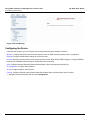
Configuring Basic Settings for the Access Point
Follow these steps to access the Access Point’s default settings:
1. Connect the Access Point as described in the Quick Install Guide (QIG) which is available along with the product
package.
2. You will follow these steps to enter the access point’s basic settings.
3. Once you have updated all the required information, ensure that you click COMMIT and then click REBOOT to
update the changes.
NOTE: Proxim recommends to create the Security profiles and Radius profiles before assigning it to VAP.
Finding and Assigning the Access Point’s IP Address
1. If your Access Point receives an IP address from the DHCP server on the network, then use the ScanTool to find its
IP address.
2. Navigate Configuration > Network IP Config page to set IP address.
•
Select the Address Type either Static or Dynamic.
•
You must assign unique IP Address for your device that is valid on your IP subnet, this would be based on the
Address Type that you have selected.
NOTE: Contact your network administrator if you need assistance in selecting an IP address for the unit.
•
You can also provide your network’s Subnet Mask, and Gateway IP address.
NOTE: If you enter the Gateway IP Address, then it mandatory that you must enter the Subnet Mask.
•
Click OK to save your changes.
30
Basic Configuration for an Enterprise
Configuring the System Name and the Country Code
AP-8000 User Guide
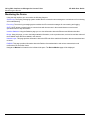
Configuring the System Name and the Country Code
1. Navigate Management > System > Information to configure the System information.
2. Enter the following parameters:
•
System Name
•
System Location
•
Select the Country Code using the drop-down list. This field displays the country in which the AP will be used.
Setting the country makes the AP automatically compliant with the rules of the regulatory domain in which it is
used by configuring the allowed frequency bands, channels, Dynamic Frequency Selection Status, Transmit
Power Control status, and power levels.
•
Click Ok.
Configuring the Wireless Information
1. Navigate to Configuration page to configure the Wireless information. Navigate to Configuration > Wireless >
Interface 1 > VAP.
NOTE: By default both the interfaces are active. If you want, you can change the default values for a single interface.
2. Click on the radio button of the index for which you want to make the changes, click Edit.
3. Configure the following parameters:
•
Enter the VAP SSID Name (wireless network name).
•
Enter the Security Profile Name.
•
Enter Radius Profile Name.
4. Click OK.
Configuring the Operational Mode
1. Click Configuration > Wireless > Interface 1 > Properties. Configure the following parameters:
•
Status: Check the Status checkbox to enable the wireless interface properties.
•
Operational Mode: Select the Operational Mode. This field indicates the operational mode of the unit.
NOTE: You can select the legacy Dot11g/a modes only after changing the current channel bandwidth to 20 MHz,
otherwise these options would not be available in the drop-down list box.
•
Current Channel Bandwidth: Select the channel bandwidth. By default it is set to 40 MHz.
•
Auto Channel selection: Enable or disable the auto channel selection for wireless interface.
•
Current Operating Channel: This will display the current operating channel on which wireless interface is
operating. If you have enabled the auto channel selection option, then this field will select the channel
automatically and also list out the other channels that are available.
•
Click OK.
Password Management
As soon as you login, ensure that you change the default passwords of the device. To change the password, navigate to
Management > Services.
•
HTTP/HTTPS: The password for the Web browser HTTP interface. Enter a password in the Password field. The
default password is “public”.
•
Telnet/SSH: The password for the CLI interface (via serial or Telnet). Enter a password between 6 and 32 characters
in the Password field. The default password is “public”.
31
Basic Configuration for an Enterprise
Configuring the Security Profile
•
AP-8000 User Guide
SNMP: The password for Read/Write access to the AP using SNMP interface. Enter a password between 6 and 32
characters in the Password field. The default password is “public”.
NOTE: This password “public” is SNMP Read/Write Community string and is also applicable to SNMP Read
Community.
•
Trap Host IP Address: Enter the IP Address for which the traps needs to be delivered. By default, an IP Address will
be available, that you can change.
NOTE: For security purposes Proxim recommends changing ALL PASSWORDS from the default “public” immediately, to
restrict access to your network devices to authorized personnel.
Configuring the Security Profile
1. Click Configuration > Security > Wireless Security.
2. Click Add in the Wireless Security CFG table to create a new entry. The Wireless Security Create Row page
displays.
3. Enter the Profile Name.
4. Authentication Mode:
•
Authentication Mode: None, then the AP allows access to stations without authentication. In other words, the
security will be disabled for that VAP.
•
Authentication Mode: WEP
— Wep Key: Enter the Wep Key. The Key Length can be 64 or 128 Bits.
• For 64-bit encryption, an encryption key is 10 hexadecimal characters (0-9 and A-F) or 5 Alpha numeric
characters.
• For 128-bit encryption, an encryption key is 26 hexadecimal characters or 13 Alpha numeric characters.
— Encryption Type: Select the Encryption type as WEP.
— Enter the Status.
•
Authentication Mode: Psk
— Encryption Type: WPA-TKIP, WPA2-AES, WPA-TKIP + WPA2-AES
— PSK: Enter the password. The limit for the passphrase is between 8 and 63 Alpha numeric characters
— Re-keying Interval: The value should be between 900 to 65535 seconds.
— Enter Status.
NOTE: When you select the encryption type as WPA-TKIP+WPA2-EAS, then the AP is considered to be in
Auto-Encryption mode, and the client will support both encryption type.
•
Authentication Mode: 802.1x
— Encryption Type: WEP, WPA-TKIP, WPA2-AES, WPA-TKIP + WPA2-AES
— Re-Keying Interval: The value should be between 900 to 65535 seconds.
— Enter Status.
NOTE: When you select the encryption type as WPA-TKIP+WPA2-EAS, then the AP is considered to be in
Auto-Encryption mode, and the client will support both encryption type. This type of security is called Dynamic
WEP.
NOTE: If you select WEP or TKIP, then the device will work on legacy rates not on 11n rates.
5. When finished configuring all parameters, click Add.
6. If you have selected a security profile of 802.1x, then you must configure a RADIUS 802.1x/EAP server. See. RADIUS
profile.
NOTE: Ensure that you assign the newly configured Security profiles to VAP.
32
Basic Configuration for an Enterprise
Configuring the Security Profile
AP-8000 User Guide
7. Click COMMIT.
33
AP-8000 User Guide
Access Point Features
5
This chapter provides you information about the features of the Access Point:
•
Configuring the Device
•
Managing the Device
•
Monitoring the Device
Configuring the Device
Following features are available under Device Configuration:
Wireless 11n Properties
The section provides information about the configuration of the VAP features defining the wireless radio parameters and
11n parameters.
This feature provides information about the configuration of the VAP features defining the wireless radio parameters and
11n parameters. The wireless feature of the Access Point enables you to use the new technology called Multiple Input
Multiple Output (MIMO), that uses several antennas to transfer multiple data streams. In this way more data can be
transferred in the same period of time. The wireless architecture is based on the cellular architecture where the systems
are divided into cells, and each cell is called the BSS.
The Wireless LAN (WLAN) can be formed of a single cell or of many cells. Each of the WLAN has an entry point which is
called Virtual Access Point (VAP). The VAP has a unique BSSID and other relevant protocols that make these VAP as
independent entity. Each of the BSSID can be configured independently so that the user can provide unique
authentication and security feature.
VAP Features
•
VAP (Virtual Access Point): This is a logical entity that exists within the physical WLAN access device. The VAP
enables a single device to be divided into layers and each layer gets assigned to different users with their usage
rights.
•
VAP SSID (Service Set Identifier): The VAP SSID is referred as a network name which is unique and this is used
for identifying a wireless network. In other words, SSID is the network name that an Access Point broadcasts,
which a device identifies for the communication between users and the Access Point.
•
VAP BSSID: This parameter represents the MAC address for the VAP BSSID.
•
VAP Broadcast SSID: The continuous announcement of the SSID in the beacons by an AP stating that is
available is called broadcast SSID. The SSID is also broadcasted in probe response frames. Broadcasting the
SSID also depends on the type of network that the AP is running on. You can disable the SSID broadcast in the
AP. Disabling of this feature will change the SSID field in the beacon and probe response of the AP an obscure
one.
•
Fragmentation Threshold: The process of dividing a MAC Service Data Unit (MSDU) into smaller MAC level
frames for transmission over the wireless network is called fragmentation. This technique reduces both the
probability and adverse effects of wireless packet corruption, and thereby improving the overall wireless network
performance. You can fragment the Unicast receiver address, whereas Broadcast/Multicast frames cannot be
fragmented, even though they exceed a fragmentation threshold. You can configure fragmentation threshold up
to 2346 bytes.
•
Security Profile Name: This parameter allows you to configure the Security profile name for Wireless VAP. It has
to be a valid security profile configured under Wireless Security.
34
Access Point Features
Configuring the Device
AP-8000 User Guide
•
RADIUS Profile Name: This parameter allows you to configure the RADIUS profile name for Wireless VAP. It has
to be a valid Radius profile configured under Security.
•
VLAN ID: This parameter is used to represent the VLAN ID for the wireless VAP. Select any value between 1 4094 to tag the VLAN ids and -1 to untag the VLAN ids. From VLAN perspective the wireless port acts as an
Access Point.
•
VLAN Priority: This parameter is used to configure the VLAN priority for Wireless VAP. By default the value is set
to 0.
•
QoS Profile Name: This parameter is used to configure the profile name for the Wireless VAP QoS.
•
Local MAC Authentication: This parameter is used to enable or disable the local MAC Access Control list.
•
RADIUS MAC Authentication: This parameter is used to enable or disable the MAC ACL for RADIUS Profiles.
•
RADIUS Accounting: This parameter is used to enable or disable the RADIUS Accounting Status.
•
Entry Status: This parameter is used to enable or disable the status of the wireless VAP.
Wireless Radio Properties
•
Operational Mode: This parameter is used to set the wireless NIC Operational mode.
•
Current Bandwidth: This parameter represents the current bandwidth that Wireless is currently operating on. It is
represented in “MHz"
•
Auto Channel Selection: This parameter indicates the AP Tx data rate that is automatically selected based on
the RF conditions.
•
Current Operating Channel: This will display the operating channel on which wireless interface is operating.
•
Auto Rate Selection: This parameter is used to configure the value for data rate for the wireless interface. For an
Access Point this value is always "Auto".
•
RTS Threshold (Request to Send Threshold): When this parameter is set to a value between 0 and 2346, the
Access Point uses the RTS mechanism for packets that are the specified size or greater. When set to 2346 (the
default setting), RTS is disabled. This parameter affects message flow control and should not be changed under
normal circumstances. The range for this field is between 0 to 2346.
•
Beacon Interval: The Beacon interval specifies the interval time between two successive beacons transmission.
You can set the value for Beacon interval between 100 ms and 1000ms for each beacon transmission.
•
TPC: The unit transmits the maximum output power for the country or regulatory domain and operational mode
selected. However, with Transmit Power Control (TPC), you can adjust the output power of the unit to a lower level
in order to reduce interference to neighboring devices or to use a higher gain antenna without violating the
maximum radiated output power allowed for your regulatory domain.
•
Cell Size: The cell size is a parameter that needs to be configured to control the range of the AP in different type
of deployment scenario. For instance, for dense AP deployment the usage of small cell size minimizes the
interference caused by one AP on another.
•
•
If the cell size is set to large, then transmit power and receive sensitivity are high.
•
If the cell is set to small, then transmit power and receive sensitivity are reduced.
DTIM (Delivery Traffic Indicator Map): DTIM determines how frequently the station must leave power save mode
and determine if the traffic is lining up for it. You can set the DTIM interval based on the applications that are being
used on the network.
11n Properties Features
•
11n AMPDU (Aggregated MAC Protocol Data Unit) Status: AMPDU (Aggregated MAC Protocol Data Unit)
specifies the aggregation of several MAC frames into a single large frame to achieve higher throughput.
•
AMPDU Max Num Frames: This field represents the AMPDU frames that are transmitted as a single PSDU by
the PHY. It can be configured up to 64 frames.
•
AMPDU Max FrameSize: This parameter is used to configure the maximum AMPDU frame size (in bytes) that
can be transmitted.
35
Access Point Features
Configuring the Device
AP-8000 User Guide
•
11n AMSDU (Aggregated MAC Service Data Unit) Status: This parameter is used define the AMSDU status for
wireless 11n interface.
•
Frequency Extension: This parameter is used to configure the frequency extension for the wireless interface.
•
Guard Interval: Guard Interval ensures that distinct transmissions do not interfere with one another. This feature
provides immunity to users. Each user is allotted a time slot to transmit their data and this time slot ends with the
guard interval. This parameter is used to configure the guard interval for the wireless interface.
•
Tx Antennas: This parameter enables the transmission antennas. This is configured as bit-mask. E.g.: 3 - 011
(binary value) - first and second antennas are enabled. 7 - 111 (binary value) - all three are enabled.
•
Rx Antennas: This parameter enables the receiving antennas. This is configured as bit-mask. E.g.: 3 - 011
(binary value) - first and second antennas are enabled. 7 - 111 (binary value) - all three are enabled.
The bottom enclosure of the device will display R and A with specific numbers, where R stands for Radio and A stands
for Antenna.
Decimal
Binary
Active Antennas
Marking of the Enclosure
1
001
First Antenna
A1
2
010
Second Antenna
A2
3
011
First and Second Antenna
A1 and A2
4
100
Third Antenna
A3
5
101
Third and First Antenna
A3 and A1
6
110
Third and Second Antenna
A3 and A2
7
111
First, Second and Third Antenna
A1, A2,a nd A3
Ethernet
The Ethernet feature provide the feasibility to view MAC address of the Ethernet Interface, speed and the mode of
transmission.
Ethernet Features
•
MAC Address: This parameter represents the MAC address of the Ethernet interface.
•
Speed: This parameter is used to view the speed of the Ethernet interface.
•
Transmit: This parameter is used for configuring the transmit mode of the Ethernet interface.
Security
The AP supports the following security features:
•
WEP Encryptions
The IEEE 802.11 standards specify an optional encryption feature, known as Wired Equivalent Privacy or WEP, that is
designed to provide a wireless LAN with a security level equal to what is found on a wired Ethernet network. WEP
encrypts the data portion of each packet exchanged on an 802.11 network using an Encryption Key (also known as a
WEP Key).
When Encryption is enabled, two 802.11 devices must have the same Encryption Keys and both devices must be
configured to use Encryption in order to communicate. If one device is configured to use Encryption but a second device
is not, then the two devices will not communicate, even if both devices have the same Encryption Keys.
•
802.1x Authentication
IEEE 802.1x is a standard that provides a means to authenticate and authorize network devices attached to a Ethernet
port. A port in the context of IEEE 802.1x is a point of attachment to the LAN, either a physical Ethernet connection or a
36
Access Point Features
Configuring the Device
AP-8000 User Guide
wireless link to an Access Point. 802.1x requires a RADIUS server and uses the Extensible Authentication Protocol
(EAP) as a standards-based authentication framework, and supports automatic key distribution for enhanced security.
The EAP-based authentication framework can easily be upgraded to keep pace with future EAP types.
Popular EAP types include:
•
EAP-Message Digest 5 (MD5): Username/Password-based authentication; does not support automatic key
distribution
•
EAP-Transport Layer Security (TLS): Certificate-based authentication (a certificate is required on the server and each
client); supports automatic key distribution
•
EAP-Tunneled Transport Layer Security (TTLS): Certificate-based authentication (a certificate is required on the
server; a client’s username/password is tunneled to the server over a secure connection); supports automatic key
distribution
•
PEAP - Protected EAP with MS-CHAP: Secure username/password-based authentication; supports automatic key
distribution
Different servers support different EAP types and each EAP type provides different features. See the documentation that
came with your RADIUS server to determine which EAP types it supports.
NOTE: The AP supports the following EAP types when Security Mode is set to 802.1x, WPA, or 802.11i (WPA2):
EAP-TLS, PEAP, and EAP-TTLS.
Authentication Process
When the Auth mode is set to 802.1x station, you need to configure your RADIUS server for authentication purposes.
There are three main components in the authentication process. The standard refers to them as:
1. Supplicant (client PC)
2. Authenticator (Access Point)
3. Authentication server (RADIUS server)
When the Security Mode is set to 802.1x Station, WPA Station, or 802.11i Station you need to configure your RADIUS
server for authentication purposes.
Prior to successful authentication, an unauthenticated client PC cannot send any data traffic through the AP device to
other systems on the LAN. The AP inhibits all data traffic from a particular client PC until the client PC is authenticated.
Regardless of its authentication status, a client PC can always exchange 802.1x messages in the clear with the AP (the
client begins encrypting data after it has been authenticated).
The AP acts as a pass-through device to facilitate communications between the client PC and the RADIUS server. The
AP (2) and the client (1) exchange 802.1x messages using an EAPOL (EAP Over LAN) protocol). Messages sent from
the client station are encapsulated by the AP and transmitted to the RADIUS (3) server using EAP extensions.
Upon receiving a reply EAP packet from the RADIUS, the message is typically forwarded to the client, after translating it
back to the EAPOL format. Negotiations take place between the client and the RADIUS server. After the client has been
successfully authenticated, the client receives an Encryption Key from the AP (if the EAP type supports automatic key
distribution). The client uses this key to encrypt data after it has been authenticated.
For 802.11a/b/g/n clients that communicate with an AP, each client receives its own unique encryption key; this is known
as Per User Per Session Encryption Keys.
•
Wi-Fi Protected Access (WPA/802.11i [WPA2])
Wi-Fi Protected Access (WPA) is a security standard designed by the Wi-Fi Alliance in conjunction with the Institute of
Electrical and Electronics Engineers (IEEE). The AP supports 802.11i (WPA2), based on the IEEE 802.11i security
standard.
WPA is a replacement for Wired Equivalent Privacy (WEP), the encryption technique specified by the original 802.11
standard. WEP has several vulnerabilities that have been widely publicized. WPA addresses these weaknesses and
provides a stronger security system to protect wireless networks.
37
Access Point Features
Configuring the Device
AP-8000 User Guide
WPA provides the following new security measures not available with WEP:
•
Improved packet encryption using the Temporal Key Integrity Protocol (TKIP) and the Michael Message Integrity
Check (MIC).
•
Per-user, per-session dynamic encryption keys:
•
•
–
Each client uses a different key to encrypt and decrypt unicast packets exchanged with the AP
–
A client's key is different for every session; it changes each time the client associates with an AP
–
The AP uses a single global key to encrypt broadcast packets that are sent to all clients simultaneously
–
Encryption keys change periodically based on the Re-keying Interval parameter
–
WPA uses 128-bit encryption keys
Dynamic Key distribution
–
The AP generates and maintains the keys for its clients
–
The AP securely delivers the appropriate keys to its clients
Client/server mutual authentication
–
802.1x
–
Pre-shared key (for networks that do not have an 802.1x solution implemented)
The AP supports the following WPA security modes:
•
WPA: The AP uses 802.1x to authenticate clients and TKIP for encryption. You should only use an EAP that supports
mutual authentication and session key generation, such as EAP-TLS, EAP-TTLS, and PEAP. See 802.1x
Authentication for details.
•
WPA-PSK (Pre-Shared Key): For networks that do not have 802.1x implemented, you can configure the AP to
authenticate clients based on a Pre-Shared Key. This is a shared secret that is manually configured on the AP and
each of its clients. The Pre-Shared Key must be 256 bits long, which is either 64 hexadecimal digits or 32
alphanumeric characters. The AP also supports a PSK Pass Phrase option to facilitate the creation of the TKIP
Pre-Shared Key (so a user can enter an easy-to-remember phrase rather than a string of characters).
•
802.11i (also known as WPA2): The AP provides security to clients according to the 802.11i standard, using 802.1x
authentication, a CCMP cipher based on AES, and re-keying.
•
802.11i-PSK (also known as WPA2 PSK): The AP uses a CCMP cipher based on AES, and encrypts frames to
clients based on a Pre-Shared Key. The Pre-Shared Key must be 256 bits long, which is either 64 hexadecimal digits
or 32 alphanumeric characters. The AP also supports a PSK Pass Phrase option to facilitate the creation of the
Pre-Shared Key (so a user can enter an easy-to-remember phrase rather than a string of characters).
NOTE: For more information on WPA, see the Wi-Fi Alliance Web site at http://www.wi-fi.org.
Recommended Security Profiles
Proxim recommends to configure following combination of the security profiles:
•
MAC-ACL + WEP/WPA-PSK
If you have enabled the MAC-ACL as Local MAC Authentication, then you need to ensure that you have the combination
of WEP/WPA-PSK security profile. Once you enable the MAC-ACL authentication then based on the MAC-ACL policy the
client will get connected.
•
Radius-MAC + WEP/WPA-PSK
If you have enabled RADIUS-MAC as RADIUS-MAC Authentication, then you need to ensure that you have the
combination of WEP/WPA-PSK security profile. If you enable RADIUS-MAC, then ensure that RADIUS Authentication
server is configured.
•
WPA2/WPA
CAUTION: Proxim recommends not to enable both Local MAC Authentication and RADIUS-MAC Authentication. You
also need to ensure that RADIUS MAC Authentication and Access Control is not enabled together.
38
Access Point Features
Configuring the Device
AP-8000 User Guide
Configuring Security Profiles
Security policies can be configured and applied on the AP as a whole, or on a per SSID basis. You can configure a
security profile for each VLAN.
The user defines a security policy by specifying one or more values for the following parameters:
•
Wireless STA types (WPA station, 802.11i (WPA2) station, WPA-PSK, and 802.11i-PSK) that can associate to the AP.
•
Authentication mechanisms (802.1x) that are used to authenticate clients for each type of station.
•
Cipher Suites (AES, TKIP, WEP, None) used for encapsulating the wireless data for each type of station.
NOTE: If you select WEP or TKIP, then the device will work on legacy rates not on 11n rates.
AP-8000 supports up to 8 security profiles and can be mapped to any of the VAPs.
Wireless Security Features
•
Profile Name: This parameter represents the name of the security profile name.
•
Authentication Mode: This parameter is used to configure the security authentication mode for wireless.
•
WEP Key: This parameter is used to configure the Wep key for wireless security.
•
Encryption Type: This parameter is used to configure the type of encryption for the wireless security.
•
PSK: This is the read parameter and used to display the security key in asterisk.
•
Rekeying Interval: This parameter represents the time interval within which the number of times the key is changed.
NOTE: Rekeying Interval in case of Dynamic WEP is WEP Rekeying Interval, whereas in the case of WPA Security
Modes is WPA Group Rekeying Interval.
RADIUS
Configuring Radius Profiles on the AP allows the administrator to define a profile for RADIUS Servers used by the system
or by a VLAN.
The network administrator can configure default RADIUS authentication servers to be used on a system-wide basis, or in
networks with VLANs enabled the administrator can also configure separate authentication servers to be used for MAC
authentication, 802.1x authentication, or RADIUS based accounting. If the back-up server are configured, then the AP
will communicate with the back-up server till the primary server is offline.
The AP communicates with the RADIUS server defined in a profile to provide the following features:
MAC Access Control Via RADIUS Authentication
If you want to control wireless access to the network and if your network includes a RADIUS Server, you can store the list
of MAC addresses on the RADIUS server rather than configure each AP individually. you can define a RADIUS profile
that specifies the IP Address of the server that contains a central list of MAC Address values identifying the authorized
stations that may access the wireless network. You must specify information for the least primary RADIUS server. The
back-up server is optional.
NOTE: Each VLAN can be configured to use a separate RADIUS server (and backup server) for MAC authentication.
MAC access control can be separately enabled for each VLAN.
802.1x Authentication using RADIUS
You must configure a primary EAP/802.1x Authentication server to use 802.1x security. A back-up server is optional.
NOTE: Each VLAN can be configured to use a separate RADIUS server (and back-up server) for 802.1x authentication.
802.1x authentication (“EAP authentication”) can be separately enabled for each VLAN.
39
Access Point Features
Configuring the Device
AP-8000 User Guide
RADIUS Accounting
Using an external RADIUS server, the AP can track and record the length of client sessions on the access point by
sending the RADIUS accounting messages per RFC2866. When a wireless client is successfully authenticated, RADIUS
accounting is initiated by sending an “Accounting Start” request to the RADIUS server. When the wireless client session
ends, an “Accounting Stop” request is sent to the RADIUS server.
NOTE: Each VLAN can be configured to use a separate RADIUS accounting server (and backup accounting server).
Session Length
Accounting sessions continue when a client reauthenticates to the same AP. Sessions are terminated when:
1. A client disassociates
2. Session-Time-out attributes are configured in the Radius server.
If the client roams from one AP to another, one session is terminated and a new session begins.
NOTE: This feature requires RADIUS authentication using 802.1x. If the clients are using Local MAC Authentication or
RADIUS MAC Authentication, then the session length is not tracked.
Authentication Attributes
•
User-Name
This Attribute indicates the name of the user that needs to be authenticated. It must be sent in Access-Request packets if
available.
•
User-Password
This Attribute indicates the password of the user to be authenticated, or the user's input following an Access-Challenge.
It is only used in Access-Request packets.
•
NAS-IP-Address
This Attribute indicates the identifying IP Address of the NAS which is requesting authentication of the user, and should
be unique to the NAS within the scope of the RADIUS server. NAS-IP-Address is only used in Access-Request packets.
•
State
This Attribute is available to be sent by the server to the client in an Access-Challenge and must be sent unmodified from
the client to the server in the new Access-Request reply to that challenge, if any.
•
Class
This Attribute is available to be sent by the server to the client in an Access-Accept and should be sent unmodified by the
client to the accounting server as part of the Accounting-Request packet if accounting is supported.
•
Session-Time-out
This Attribute sets the maximum number of seconds of service to be provided to the user before termination of the
session or prompt. This Attribute is available to be sent by the server to the client in an Access-Accept or
Access-Challenge.
•
Termination-Action
This Attribute indicates what action the NAS should take when the specified service is completed. It is only used in
Access-Accept packets.
•
Called-Station-Id
This Attribute allows the NAS to send in the Access-Request packet the phone number that the user called, using Dialed
Number Identification (DNIS) or similar technology. It is only used in Access- Request packets.
•
Calling-Station-Id
40
Access Point Features
Configuring the Device
AP-8000 User Guide
This Attribute allows the NAS to send in the Access-Request packet the phone number that the call came from, using
Automatic Number Identification (ANI) or similar technology. It is only used in Access-Request packets.
•
Acct-Interim-Interval
Obtained during the Authentication process and used for determining the time interval for sending Accounting Update
messages.
NOTE: If this attribute is not obtained from the Radius Server, the AP uses default value of 300 seconds for updating
the accounting messages.
Accounting Attributes
•
Acct-Status-Type
This attribute indicates whether this Accounting-Request marks the beginning of the user service (Start) or the end
(Stop).
•
Acct-Input-Octets
This attribute indicates how many octets have been received from the port over the course of this service being provided,
and can only be present in Accounting-Request records where the Acct-Status-Type is set to Stop.
•
Acct-Output-Octets
This attribute indicates how many octets have been sent to the port in the course of delivering this service, and can only
be present in Accounting-Request records where the Acct-Status-Type is set to Stop.
•
Acct-Session-Id
This attribute is a unique Accounting ID to make it easy to match start and stop records in a log file. The start and stop
records for a given session will have the same Acct-Session-Id.
•
Acct-Authentic
This attribute is included in an Accounting-Request to indicate how the user was authenticated, whether by RADIUS, the
NAS itself, or another remote authentication protocol.
•
Acct-Session-Time
This attribute indicates how many seconds the user has received service for, and can only be present in
Accounting-Request records where the Acct-Status-Type is set to Stop.
•
Acct-Input-Packets
This attribute indicates how many packets have been received from the port over the course of this service being
provided to a Framed User, and can only be present in Accounting-Request records where the Acct-Status-Type is set to
Stop.
•
Acct-Output-Packets
This attribute indicates how many packets have been sent to the port in the course of delivering this service to a Framed
User, and can only be present in Accounting-Request records where the Acct-Status-Type is set to Stop
•
Acct-Terminate-Cause
This attribute indicates how the session was terminated, and can only be present in Accounting- Request records where
the Acct-Status-Type is set to Stop.
RADIUS Features
The parameters that can be configured:
•
Profile Name: This parameter provides the RADIUS profile name. Profile name is o identify a set of four RADIUS
servers configured one each per Accounting, Authentication, Secondary Accounting and Secondary Authentication.
41
Access Point Features
Configuring the Device
AP-8000 User Guide
•
Max ReTransmissions: This parameter represents the communication between the AP and the server.
•
Message Response Time: This parameter represents the response time in seconds that the AP should wait for the
RADIUS server to respond to a request. The range is between 3 to 12 seconds.
•
Re Authentication Period: This parameter represents the time period after which the AP must reauthenticate the
client with the RADIUS server.
NOTE: If the value is set to “0”, then the re-authentication is disabled. This parameter does not apply for clients using
RADIUS MAC Authentication.
You have four radius profiles available for configurations:
•
Server Type: There are four radius profiles available for configurations: Primary Authentication Server, Secondary
Authentication Server, Primary Accounting Server, and Secondary Accounting Server.
•
IP Address: The parameter represents the IP address of the Radius servers.
•
Server Port: This parameter represents the port number which the AP and the server will use to communicate.
•
Shared Secret: This parameter represents the password shared by the RADIUS server and the AP.
MAC ACL Features
•
Operation Type: This parameter is used for configure MAC ACL operation type.
While adding the MAC ACL row, following are the parameters:
•
MAC Address: This parameter represents the valid MAC address of the MAC ACL.
•
Comment: This parameter is an optional and is used for entering a comment.
QoS
Wi-Fi Multimedia (WMM)/Quality of Service (QoS) Introduction
The AP supports Wi-Fi Multimedia (WMM), which is a solution for QoS functionality based on the IEEE 802.11e
specification. WMM defines enhancements to the MAC for wireless LAN applications with Quality of Service
requirements, which include transport of voice and video traffic over IEEE 802.11 wireless LANs.
The enhancement are in the form of changes in protocol frame formats (addition of new fields and information elements)
addition of new messages, definition of new protocol actions, channel access mechanisms (differentiated control of
access to medium) and network elements (QoS/WME aware APs, STAs), and configuration management.
WME supports Enhanced Distributed Channel Access (EDCA) for prioritized QoS services. The WME/QoS feature can
be enabled or disabled per VAP.
Enhanced Distributed Channel Access (EDCA)
WME uses Enhanced Distributed Channel Access, a prioritized CSMA/CA access mechanism used by WME-enabled
clients/AP in a WME enabled BSS to realize different classes of differentiated Channel Access.
A wireless Entity is defined as all wireless clients and APs in the wireless medium contending for the common wireless
medium. EDCA uses a separate channel access function for each of the Access Categories (Index) within a wireless
entity. Each channel access function in a wireless entity that contends for the wireless medium as if it were a separate
client contending for the wireless medium. Different channel access functions in a given Wireless Entity contend among
themselves for access to the wireless medium in addition to contending with other clients.
STA EDCA Table and AP EDCA Table
This page is used to configure the client (STA) and AP Enhanced Distributed Channel Access (EDCA) parameters. You
can modify the EDCA values for Wireless.
The EDCA parameter set provides information needed by the client stations for proper QoS operation during the wireless
contention period. These parameters are used by the QoS enabled AP to establish policy, to change policies when
42
Access Point Features
Configuring the Device
AP-8000 User Guide
accepting new stations or new traffic, or to adapt to changes in the offered load. The EDCA parameters assign priorities
to traffic types where higher priority packets gain access to the wireless medium more frequently than lower priority
packets.
NOTE: Default recommended values for EDCA parameters have been defined; Proxim recommends not to modify
EDCA parameters unless strictly necessary.
QoS EDCA Features
•
Profile Name: This parameter is used to displays the name for the Wireless QoS EDCA profile.
•
STA CW Min: This parameter is used to configure the minimum value for CW for the wireless QoS EDCA profile.
•
STA CW Max: This parameter is used to configure the maximum value for CW for the wireless QoS EDCA profile.
•
STA AI FSN: This parameter is used for configure the AIFSN value for the wireless QoS EDCA profile.
•
STA TXOP: The parameter is used to configure TXOP value for wireless QoS EDCA profile.
•
STA ACM: This parameter is used to configure the status for ACM.
•
AP CW Min: This parameter is used to configure the minimum value for CW for the AP.
•
AP CW Max: This parameter is used to configure the maximum value for CW for the AP.
•
AP TXOP: This parameter is used to configure the TXOP value for the AP.
•
AP ACM: This parameter is used to configure the status of the APACM for the QoS EDCA profile.
802.1D to IP DSCP Mapping Table Features
•
801.1D to IPDSCP index: This parameter indicates IP DSCP index corresponding to 802.1D priority.
•
Lower Limit: This parameter is used to specify IP DSCP lower limit.
•
Upper Limit: This parameter is used to specify IP DSCP upper limit.
802.1D to 802.1p Mapping Table Features
•
801.1D Priority: This parameter is used to specify the 802.1d priority and is used as the secondary index to the
802.1D to 802.1p mapping table.
•
802.1p Priority: The parameter is used to specify the 802.1D to be mapped to a 802.1p priority.
QoS Profile Features
•
QoS Profile Name: This parameter displays the name of the QoS profile name that been assigned.
•
Policy Name: This parameter displays the QoS Policy profile name.
•
EDCA Profile Name: This parameter displays the name of the QoS EDCA profile name.
•
QoS NACK Status: This parameter is used to configure the status of the QoS profile ACK status.
QoS Policy Features
•
Policy Name: This parameter displays the policy name.
•
Policy Type: This parameter is used to configure the QoS type. Policy type can be configured for the following;
Inbound Layer2, Inbound Layer3, Outbound Layer2, and Outbound Layer3.
•
Priority Mapping: This parameter is used for configuring the primary index to the QoS 802.1D to 802.1p mapping
table.
•
Marking Status: This parameter is used to enable or disable the QoS marking.
IP Configuration
The network (internet (TCP/IP)) settings for the Access Point can be either entered manually (static IP address, subnet
mask, and gateway IP address) or obtained automatically (dynamic).
43
Access Point Features
Configuring the Device
AP-8000 User Guide
•
Address Type: Set this parameter to Dynamic to configure the Access Point as a Dynamic Host Configuration
Protocol (DHCP) client; the Access Point will obtain IP settings from a network DHCP server automatically during the
boot-up. If you do not have a DHCP server or if you want to manually configure the Access Point’s IP settings, set this
parameter to Static.
•
IP Address: This parameter represents the IP Address of the Access Point. When IP Address Assignment Type is set
to Dynamic, this field is read-only and reports the unit’s current IP address. The Access Point will default to
169.254.128.132, if it cannot obtain an address from a DHCP server.
•
Subnet Mask: The Access Point’s subnet mask. When Address Type is set to Dynamic, this field is read-only and
reports the unit’s current subnet mask. The subnet mask will default to 255.255.0.0 if the unit cannot obtain one from
a DHCP server.
•
Gateway IP Address: The IP address of the Access Point’s gateway. When Address Type is set to Dynamic, this field
is read-only and reports the IP address of the unit’s gateway. The gateway IP address will default to 169.254.128.133
if the unit cannot obtain an address from a DHCP server.
VLAN
Virtual Local Area Networks (VLANs) are logical groupings of network hosts. Defined by software settings, other VLAN
members or resources appear (to clients) to be on the same physical segment, no matter where they are attached on the
logical LAN or WAN segment. They simplify traffic flow between clients and their frequently-used or restricted resources.
VLANs now extend as far as the reach of the Access Point signal. Clients can be segmented into wireless sub-networks
via SSID and VLAN assignment. A Client can access the network by connecting to an AP configured to support its
assigned SSID/VLAN.
AP devices are fully VLAN-ready; however, by default VLAN support is disabled. Before enabling VLAN support, certain
network settings should be configured, and network resources such as a VLAN-aware switch, a RADIUS server, and
possibly a DHCP server should be available.
Once enabled, VLANs are used to conveniently, efficiently, and easily manage your network in the following ways:
•
Manage adds, moves, and changes from a single point of contact
•
Define and monitor groups
•
Reduce broadcast and multicast traffic to unnecessary destinations
–
•
Improve network performance and reduce latency
Increase security
–
Secure network restricts members to resources on their own VLAN
–
Clients roam without compromising security
VLAN tagged data is collected and distributed through an AP's wireless interface(s) based on Network Name (SSID). An
Ethernet port on the Access Point connects a wireless cell or network to a wired backbone. The Access Points
communicate across a VLAN-capable switch that analyzes VLAN-tagged packet headers and directs traffic to the
appropriate ports. On the wired network, a RADIUS server authenticates traffic and a DHCP server manages IP
addresses for the VLAN(s). Resources like servers and printers may be present, and a hub may include multiple APs,
extending the network over a larger area.
Access Points that are not VLAN-capable typically transmit broadcast and multicast traffic to all wireless Network
Interface Cards (NICs). This process wastes wireless bandwidth and degrades throughput performance. In comparison,
a VLAN-capable AP is designed to efficiently manage delivery of broadcast, multicast, and unicast traffic to wireless
clients.
The AP assigns clients to a VLAN based on a Network Name (SSID). The AP can support up to 4 SSIDs per radio, and
multiple SSIDs can have same VLAN Id.
NOTE: It is not required that each VAP should have unique VLAN ID.
44
Access Point Features
Configuring the Device
AP-8000 User Guide
The AP matches packets transmitted or received to a network name with the associated VLAN. Traffic received by a
VLAN is only sent on the wireless interface associated with that same VLAN. This eliminates unnecessary traffic on the
wireless LAN, conserving bandwidth and maximizing throughput.
Typical User VLAN Configurations
VLANs segment network traffic into workgroups, which enable you to limit broadcast and multicast traffic. Workgroups
enable clients from different VLANs to access different resources using the same network infrastructure. Clients using the
same physical network are limited to those resources available to their workgroup.
The AP can segment users into a maximum of 4 different workgroups per radio, based on an SSID/VLAN grouping.
The VLANs are very useful to segment the LAN into different broadcast domains. This helps in reducing the broadcast
domain by separating the logical segments of a LAN. VLANs can operate in different modes based on the incoming
traffic.
VLAN on Ethernet port of AP is configured in the Transparent mode. When the VLAN status is disabled, then the bridge
will forward the frames received on wireless interface as it is.
Once the VLAN status is enabled, all the VAP ports are configured with a valid VLAN ID (1 to 4094) and all the ports will
act as an access port. All untagged packets received from clients will be tagged by VAP port with VAP VLAN ID and then
forwarded to its destination port.
The VLAN has a 32-bit VLAN Header format as mentioned below:
TPID
Priority
16
•
TPID - Tag Protocol Identifier
•
CFI - Canonical Format Identifier
•
Priority - 0 to 7 (value)
•
VID - VLAN ID (1 to 4094)
3
CFI
VID
1
12
VLAN Features
•
VLAN Status: This parameter is used to configure the VLAN status of the device.
•
Management VLAN ID: This parameter is used to configure the Management VLAN ID. The management stations
must tag the management frames they send to the device with the management VLAN ID.
Filtering
The Access Point’s Packet Filtering features help control the amount of traffic exchanged between the wired and wireless
networks.
Intra BSS Filtering
The wireless clients that associate with a certain AP form the Basic Service Set (BSS) of a network infrastructure. By
default, wireless subscribers in the same BSS can communicate with each other. However, some administrators may
wish to block traffic between wireless subscribers that are associated with the same AP to prevent unauthorized
communication and to conserve bandwidth. This feature enables you to prevent wireless subscribers within a BSS from
exchanging traffic.
Although this feature is generally enabled in public access environments, Enterprise LAN administrators use it conserve
wireless bandwidth by limiting communication between wireless clients. For example, this feature prevents peer-to-peer
file sharing or gaming over the wireless network.
•
If you select to block the traffic, then the wireless traffic between the clients associated with the same or different BSS
(Basic Service Set) will not be able to communicate with each other.
45
Access Point Features
Configuring the Device
•
AP-8000 User Guide
If you select to passthru, then the wireless traffic between the clients associated with the same or different BSS will be
able to communicate with each other.
The Filtering feature supports the filtering for following protocol layers:
Ethernet Layer Filtering
Static MAC Filtering
The Static MAC Address filter optimizes the performance of a wireless (and wired) network. When this feature is properly
configured, the AP can block traffic between wired devices and wireless devices based on MAC address.
For example, you can set up a Static MAC filter to prevent wireless clients from communicating with a specific server on
the Ethernet network. You can also use this filter to block unnecessary multicast packets from being forwarded to the
wireless network.
NOTE: The Static MAC Filter is an advanced feature. You may find it easier to control wireless traffic via other filtering
options, such as Ethernet Protocol Filtering.
Each static MAC entry contains the following fields:
•
Wired MAC Address
•
Wired MAC Mask
•
Wireless MAC Address
•
Wireless MAC mask
•
Comment
•
Status
Each MAC Address or Mask is comprised of 12 hexadecimal digits (0-9, A-F) that correspond to a 48-bit identifier. (Each
hexadecimal digit represents 4 bits (0 or 1)).
Taken together, a MAC Address/Mask pair specifies an address or a range of MAC addresses that the AP will look for
when examining packets. The AP uses Boolean logic to perform an “AND” operation between the MAC Address and the
Mask at the bit level. However, for most users, you do not need to think in terms of bits. It should be sufficient to create a
filter using only the hexadecimal digits 0 and F in the Mask (where 0 is any value and F is the value specified in the MAC
address). A Mask of 00:00:00:00:00:00 corresponds to all MAC addresses, and a Mask of FF:FF:FF:FF:FF:FF applies
only to the specified MAC Address.
For example, if the MAC Address is 00:20:A6:12:54:C3 and the Mask is FF:FF:FF:00:00:00, the AP will examine the
source and destination addresses of each packet looking for any MAC address starting with 00:20:A6. If the Mask is
FF:FF:FF:FF:FF:FF, the AP will only look for the specific MAC address (in this case, 00:20:A6:12:54:C3).
When creating a filter, you can configure the Wired parameters only, the Wireless parameters only, or both sets of
parameters. Which parameters to configure depends upon the traffic that you want to block:
•
To prevent all traffic from a specific wired MAC address from being forwarded to the wireless network, configure only
the Wired MAC Address and Wired Mask (leave the Wireless MAC Address and Wireless Mask set to all zeros).
•
To prevent all traffic from a specific wireless MAC address from being forwarded to the wired network, configure only
the Wireless MAC address and Wireless Mask (leave the Wired MAC Address and Wired Mask set to all zeros).
•
To block traffic between a specific wired MAC address and a specific wireless MAC address, configure all four
parameters. Configure the wired and wireless MAC address and set the wired and wireless mask to all Fs.
•
To prevent all traffic from a specific wired Group MAC address from being forwarded to the wireless network,
configure only the Wired MAC Address and Wired Mask (leave the Wireless MAC Address and Wireless Mask set to
all zeros).
•
To prevent all traffic from a specific wireless Group MAC address from being forwarded to the wired network,
configure only the Wireless MAC address and Wireless Mask (leave the Wired MAC Address and Wired Mask set to
all zeros).
46
Access Point Features
Configuring the Device
AP-8000 User Guide
•
To block traffic between a specific wired Group MAC address and a specific wireless Group MAC address, configure
all four parameters.
•
To prevent the traffic between wired and wireless MAC and Group MAC address pair, configure any combination four.
A maximum of 64 entries can be created in the Static MAC filter table. To create an entry, click Add and enter the
appropriate MAC addresses and Masks to setup a filter. The entry is enabled automatically when saved.
NOTE: You can specify the MAC addresses and their Masks and also add or delete the entries. Wired and Wireless
MAC Address cannot have broadcast and multicast MAC address.
Ethernet Protocol Filtering
The Ethernet Protocol Filtering blocks or forwards packets based on the Ethernet protocols. The default table along with
the list of Ethernet protocols is made available. You can add, modify or delete the entries that you have created, but the
default values cannot be deleted. You have two options to set the filter status based on the protocol type:
•
Passthru: This filter status will allow the packets to pass through.
•
Block: This filter status will block the packets.
You can enter a maximum number of 64 entries for a table.
IP Layer
IP Protocol Filtering
This filtering type is also known as Advanced Filtering. The device is provided with some known protocol entries. Using
this filter type you can block the specific IP Protocol traffic. You can enable or disable the entries as well the change the
direction of the traffic.
TCP/UDP Layer
Port-based filtering enables you to control wireless user access to network services by selectively blocking TCP/UDP
protocols through the AP. A user specifies a Protocol Name, Port Number, Port Type (TCP, UDP, or TCP/UDP), and
filtering interfaces (only Wireless, only Ethernet or Both) in order to block access to services, such as Telnet and FTP,
and traffic, such as NETBIOS and HTTP. You can enter up to maximum 64 entries for a table.
For example, an AP with the following configuration would discard frames received on its Ethernet interface with a UDP
destination port number of 137, effectively blocking NETBIOS Name Service packets.
Protocol Name
Port Number
Port Type
Filter Interface
Entry Status
(Enable/Disable)
NETBIOS Name Service
137
UDP
Ethernet
Enable
Filtering Features
•
Global Filter Flag: This parameter is used to enable or disable the filtering tag. If you disable this filtering tag, then
the no filtering feature will be applicable.
•
Intra BSS Filtering: This parameter is used configure wireless to wireless communication.
Protocol Filter
•
Filtering Control: This parameter is used to enable or disable this feature.
•
Filtering Type: This parameter is used to configure the filtering type. If the specific protocol is not available on the
protocol filter table, then the filtering type would be performed on the packet that is being transmitted.
•
Protocol Name: This parameter represents the Ethernet protocol filtering name.
•
Protocol Number: This parameter represents the Ethernet protocol filtering number.
47
Access Point Features
Managing the Device
•
AP-8000 User Guide
Filter Status: This parameter is used for configuring the status of the Ethernet protocol filtering.
Static MAC Address Filter
•
Wired MAC Address: This parameter represents the MAC address for the filter wired address.
•
Wired MAC Mask: This parameter represents the MAC address for the filter wired Mask.
•
Wireless MAC Address: This parameter represents the MAC address for the filter wireless address.
•
Wireless MAC Mask: This parameter represents the MAC address for the filter wireless Mask.
•
Comment: This parameter is used for entering the comment for the Static MAC filter table and this ia an optional
parameter.
Advanced Filtering
•
Protocol Name: This parameter is used to represent the protocol name that is to be filtered.
•
Direction: This parameter represents the direction of the individual entry in the advanced filter table. The direction
can be enabled either for Ethernet to Wireless, Wireless to Ethernet or both ways.
TCP/UDP Port Filter
•
Filter Control: This parameter is used for configuring the status for the TCP/UDP port filter.
•
Protocol Name: This parameter is used to configure the protocol name.
•
Port Number: This parameter represents the TCP/UDP port filter number.
•
Port Type: This parameter represents the port type for this TcpUdp Port filter table entry. The object can be either TCP
or UDP or TCP/UDP.
•
Filter Interface: This parameter is used to configure the interface. By default, the object is set to All Interfaces. The
filter can be enabled either for Ethernet, Wireless or All Interface.
For more information on how to configure the above mentioned features, refer the following chapters:
•
Using Web Interface: Using Web Interface to Manage the Access Point
•
Using SNMP Interface: Using SNMP Interface to Manage the Access Point
•
CLI Interface: Using CLI to Manage the Access Point
Managing the Device
Following features are available under Device Management:
System Information
This feature of the Access Point provides system specific information such as system name and contact information. It
also provides the inventory management information such as Access Point’s hardware, software, version and other
information about the AP’s installed components.
System Information Features
•
System Up-Time: This is a read-only field that displays how long the Access Point has been operational since its last
reboot.
•
System Description: This parameter provides the description of the system. This is a read-only field that reports the
Access Point’s name, serial number, current image software version, and current bootloader software version.
•
System Name: This parameter provides the system name that is assigned. By default this displays the complete
domain name.
•
Email: The email address of the person responsible for the AP.
48
Access Point Features
Managing the Device
AP-8000 User Guide
•
Phone Number: The phone number of the person responsible for the AP.
•
Location: The location where the AP is installed.
•
GPS Longitude: The longitude at which the AP is installed. Enter the value in the format required by your network
management system.
•
GPS Latitude: The latitude at which the AP is installed. Enter the value in the format required by your network
management system.
•
GPS Altitude: The altitude at which the AP is installed. Enter the value in the format required by your network
management system.
•
Country Code: The country in which the AP will be used. Setting the country makes the AP automatically compliant
with the rules of the regulatory domain in which it is used by configuring the allowed frequency bands, channels,
Dynamic Frequency Selection Status, Transmit Power Control status, and power levels.
System Inventory Management Table Features
•
Serial Number: This parameter identifies the system component serial number
•
Name: This parameter identifies the system component name.
•
Component ID: This parameter identifies the system component identification.
•
Variant: This parameter identifies the system component variant number.
•
Release Version: This parameter identifies the system component release version number.
•
Major Version: This parameter identifies the system component major version number.
•
Minor Version: This parameters identifies the system component minor version number.
Upgrading the Firmware
Using the File Management option you can manage your files through HTTP and TFTP.
The HTTP Interface (Web browser Interface) provides easy access to configuration settings and network statistics from
any computer on the network. You can access the HTTP Interface over your LAN (switch, hub etc) over the Internet, or
with a “cross-over” Ethernet cable connected directly to your computer.
Using the TFTP server you can transfer files across a network. You can upload files from the AP for backup or copying,
you can download the files for configuration and AP image upgrades.
File Management
Using the File Management category you can upgrade your device firmware:
•
Downloading files (Config, image) to the AP using one of the two methods is called Update Device.
•
Uploading files (Config, Event Log) from the AP is called Retrieve From Device.
TFTP File Transfer Guidelines
A TFTP server must be running and configured to point to the directory containing the file. If you do not have a TFTP
server on your system, install the TFTP server from the installation CD.
HTTP File Transfer Guidelines
HTTP file transfer can be performed either with or without SSL enabled. HTTP file transfers with SSL require enabling
Secure Management and Secure Management and Secure Socket Layer. HTTP transfers that use SSL may take
additional time.
Image Error Checking during File Transfer
The Access Point performs checks to verify that an image downloaded through HTTP or TFTP is valid. The following
checks are performed on the downloaded image:
49
Access Point Features
Managing the Device
•
Zero image size
•
Large image size
•
AP image
•
Digital signature verification
AP-8000 User Guide
If any of the above checks fails on the download image, the Access Point deletes the download image and retains the old
image. Otherwise, if all checks pass successfully, the AP detects the old image and retains the download image.
These checks are to ensure that the AP does not enter an invalid image state. The storage of the two images is only
temporary to ensure the proper verification; the two images will not be stored in the AP permanently.
Update Device Using HTTP - Features
•
File Type: This parameter represents the type of file being downloaded to the device.
•
File Name: This parameter represents the filename to be downloaded.
Update Device Using TFTP - Features
•
Server IP Address: This parameter represents the IP address for the TFTP server.
•
File Name: This parameter represents the filename to upload or download to the TFTP server.
•
File Type: This parameter represents the type of file being downloaded to the device.
•
Operation: This parameter represents the type of operation that has to be completed. The option that are provided
are: None, Update, and Update and Reboot.
Retrieve From Device Using HTTP - Features
•
File Type: This parameter represents the type of file being uploaded to the device.
Retrieve From Device Using TFTP - Features
•
Server IP Address: This parameter represents the IP address for the TFTP server.
•
File Name: This parameter represents the filename to upload or download to the TFTP server.
•
File Type: This parameter represents the type of file being uploaded to the device.
Password Management
The Management Services feature provides a consolidated page where you can configure all the required passwords for
the Access Point.
NOTE: No special characters are allowed while configuring the passwords.
Services Features
HTTP Password: This parameter is used to set the HTTP login password. This password should be in alphanumeric with
minimum of 8 and maximum of 32 characters.
HTTP: This parameter represents the TCP/IP port by which the HTTP server will be accessible.
HTTPS: This parameter is used to enable or disable the HTTPS access to the device from any host.
Telnet/SSH Password: This parameter is used to set the Telnet/SSH login password. This password should be in
alphanumeric with minimum of 6 and maximum of 32 characters.
Telnet: This parameter is used to enable or disable the Telnet access to the device from any host.
SSH: This parameter is used to enable or disable the SSH access to the device from any host.
SNMP: This parameter allows to enable or disable the SNMP access.
50
Access Point Features
Monitoring the Device
AP-8000 User Guide
SNMP Password: This parameter represents the read-only community name used in the SNMP protocol. It is sent along
with each SNMP Get-Request to allow or deny access to device. This password should be same as read password set at
the NMS or mib browser). This password should be in alphanumeric with minimum of 6 and maximum of 32 characters.
Trap Host IP Address: This parameter represents the IP address of the management station that will receive SNMP
traps from the device.
Management Access Control
The Management Access Control feature provides you an option of controlling the interface.
Management Access Control Feature Table Features:
•
Access Table Status: This parameter is used to enable or disable the Access Control Table. By default it is disabled.
Please check to enable and uncheck to disable. If this parameter is enabled the device can be managed only with
configured IP Address list.
•
IP Address: This parameter represents the IPv4 IP Address for which the traffic need to be passed.
For more information on how to configure the above mentioned features, refer the following chapters:
•
Using Web Interface: Using Web Interface to Manage the Access Point
•
Using SNMP Interface: Using SNMP Interface to Manage the Access Point
•
CLI Interface: Using CLI to Manage the Access Point
Monitoring the Device
Following features are available under Device Monitor:
System Log
The Syslog messaging system enables the AP to transmit event messages to a central server for monitoring and
troubleshooting. Syslog Events are logged according to the level of detail specified by the administrator. Logging only
urgent system messages will create a far smaller, more easily read log than a log of every event the system encounters.
If the SysLog server is configured, then System Log messages can be sent to other hosts.
System Log Features
•
Log Status: This parameter is used to configure the status for the SysLog. Select enable to enable the Syslog status
or disable to disable the syslog status.
•
Log Priority: This parameter is used to configure the priority for the syslog. Select 1 for emergency, 2 for alert, 3 for
critical, 4 for error, 5 for warning, 6 for notice, info for 7 and 8 for debug.
System Log Host Table Features
•
IP Address: This parameter is used to represent the IP address of the Sys Log table.
•
Port: This parameter is used to represents the host port for the Sys Log table.
•
Host Comment: This parameter is used to configure the status of the Syslog host entry table.
Event Log
The Event Log keeps track of events that occur during the operation of the device. The Event Log displays messages
that may not be captured by System Traps, such as the Transmit Power for the Frequency Channel selected.
Event Log Features
•
Log Priority: This parameter is used to configure the priority for the event log table. The options are: Emergency,
Alert, Critical, Error, Warning, Notice, Info, and Debug.
51
Access Point Features
Monitoring the Device
AP-8000 User Guide
SNTP
SNTP allows a network entity to communicate with time servers in the network/internet to retrieve and synchronize time
of day information. When this feature is enabled, the AP will attempt to retrieve the time of day information from the
configured time servers (primary or secondary), and, if successful, will update the relevant time objects in the AP. If the
AP fails to retrieve the information after three attempts, the AP will use the system uptime and update the relevant time
objects. If this feature is disabled, the user cannot configure the date and time parameters.
SNTP Features
•
SNTP Status: This parameter is used to enable or disable the SNTP functionality.
•
Primary Server Name Or IP Address: This parameter is used for the primary SNTP server IP address name.
•
Secondary Server Name Or IP Address: This parameter is used for the secondary SNTP server IP address name.
•
Time Zone: This parameter is used to specify the appropriate time zone.
Day Light Saving Time: This parameter is used to indicate the number of hours to adjust for Daylight Saving Time.
Interface Statistics
Statistics feature provides you the information about the various interfaces that are available for the Access Points. The
sub-features that are available are described below:
Station Statistics
Station Statistics display information on wireless clients attached to the AP.
•
VAP Number: The VAP number on which the client is connected with the AP.
•
MAC Address: The MAC address of the wireless client for which the statistics are gathered.
•
Rx Data Frames: The number of data frames that are received.
•
Tx Data Frames: The number of data frames that are transmitted.
•
RSSI: This represents the Received Signal Strength of the Station.
•
Tx Rate: This parameter represents the transmission rate of the station.
•
State: This parameter represents the present status of the station.
Wireless Statistics
Wireless Statistics display information on the wireless interface.
•
Description: Information about the interface (e.g., the name of the manufacturer, the product name and the version of
the hardware interface).
•
Type: This displays the type of interface.
•
MTU: Maximum Transfer Unit is the largest size of IP datagram which may be transferred using a specific data link
connection. The size of MTU may vary greatly between different links.
•
Physical Address: The wireless interface’s address at the protocol layer immediately below the network layer in the
protocol stack.
•
Operational Status: The current state of the interface: Up (ready to pass packets), Down (not ready to pass packets,
or Testing (testing and unable to pass packets).
•
Last Change: The value of the sysUpTime object at the time the interface entered its current operational state.
•
In Octets: The total number of octets received on the interface, including framing characters.
•
In Ucast Packets: The number of subnetwork unicast packets delivered to a higher-layer protocol.
•
In Nucast Packets: The number of non-unicast (i.e., subnetwork-broadcast or subnetwork-multicast) packets
delivered to a higher-layer protocol.
52
Access Point Features
Monitoring the Device
AP-8000 User Guide
•
In Errors: The number of inbound packets that contained errors preventing them from being deliverable to a
higher-layer protocol.
•
Out Octets (bytes): The total number of octets transmitted out of the interface, including framing characters.
•
Out Ucast Packets: The total number of packets that higher-level protocols requested to be transmitted to a
subnetwork-unicast address, including those that were discarded or not sent.
•
Out Discards: The number of error-free outbound packets chosen to be discarded to prevent their being transmitted.
One possible reason for discarding such a packet could be to free up buffer space.
•
Out Errors: The number of outbound packets that could not be transmitted because of errors.
Ethernet Statistics
Ethernet Statistics display information on the Ethernet interface.
•
Description: Information about the interface (e.g., the name of the manufacturer, the product name and the version of
the hardware interface).
•
Type: This displays the type of interface.
•
MTU: Maximum Transfer Unit is the largest size of IP datagram which may be transferred using a specific data link
connection. The size of MTU may vary greatly between different links.
•
Physical Address: The wireless interface’s address at the protocol layer immediately below the network layer in the
protocol stack.
•
Operational Status: The current state of the interface: Up (ready to pass packets), Down (not ready to pass packets,
or Testing (testing and unable to pass packets).
•
Last Change: The value of the sysUpTime object at the time the interface entered its current operational state.
•
In Octets: The total number of octets received on the interface, including framing characters.
•
In Ucast Packets: The number of subnetwork unicast packets delivered to a higher-layer protocol.
•
In Nucast Packets: The number of non-unicast (i.e., subnetwork-broadcast or subnetwork-multicast) packets
delivered to a higher-layer protocol.
•
In Errors: The number of inbound packets that contained errors preventing them from being deliverable to a
higher-layer protocol.
•
Out Octets (bytes): The total number of octets transmitted out of the interface, including framing characters.
•
Out Ucast Packets: The total number of packets that higher-level protocols requested be transmitted to a
subnetwork-unicast address, including those that were discarded or not sent.
•
Out Discards: The number of error-free outbound packets chosen to be discarded to prevent their being transmitted.
One possible reason for discarding such a packet could be to free up buffer space.
•
Out Errors: The number of outbound packets that could not be transmitted because of errors.
Bridge
The AP is a bridge between the wired and the wireless networking devices. Bridge Statistics display information that is
available on the Bridge.
Bridge Statistics
•
Description: Information about the interface (e.g., the name of the manufacturer, the product name and the
version of the hardware interface).
•
Type: This displays the type of interface.
•
MTU: Maximum Transfer Unit is the largest size of IP datagram which may be transferred using a specific data link
connection. The size of MTU may vary greatly between different links
•
Physical Address: The wireless interface’s address at the protocol layer immediately below the network layer in
the protocol stack.
53
Access Point Features
Monitoring the Device
AP-8000 User Guide
•
Operational Status: The current state of the interface: Up (ready to pass packets), Down (not ready to pass
packets, or Testing (testing and unable to pass packets).
•
Last Change: The value of the sysUpTime object at the time the interface entered its current operational state.
•
In Octets: The total number of octets received on the interface, including framing characters.
•
In Ucast Packets: The number of subnetwork unicast packets delivered to a higher-layer protocol.
•
In Nucast Packets: The number of non-unicast (i.e., subnetwork-broadcast or subnetwork-multicast) packets
delivered to a higher-layer protocol.
•
In Errors: The number of inbound packets that contained errors preventing them from being deliverable to a
higher-layer protocol.
•
Out Octets (bytes): The total number of octets transmitted out of the interface, including framing characters.
•
Out Ucast Packets: The total number of packets that higher-level protocols requested be transmitted to a
subnetwork-unicast address, including those that were discarded or not sent.
•
Out Discards: The number of error-free outbound packets chosen to be discarded to prevent their being transmitted.
One possible reason for discarding such a packet could be to free up buffer space.
•
Out Errors: The number of outbound packets that could not be transmitted because of errors.
Network Layer
This page provides information of the IP ARP and for the received and transmitted messages.
RADIUS
Authentication Statistics
The feature description are:
•
Round Trip Time: This parameter represents the round trip time for messages exchanged between radius client
and authentication server since client startup.
•
Stats Requests: This parameter represents the number of RADIUS Access Requests messages transmitted from
the client to the server since client startup.
•
Retransmissions: This parameter represents the number of time the RADIUS Access Requests is being
transmitted to the server from the AP since the AP’s startup.
•
Access Accepts: This parameter indicates the number of RADIUS Access Accept messages received since
system startup.
•
Access Rejects: This parameter represents the number of RADIUS Access Rejects messages received since the
system startup.
•
Access Challenges: This parameter represents the number of RADIUS Access Challenges messages received
since the system startup.
•
Stats Responses: This parameter represents the number of RADIUS response packets received by the AP since
startup.
•
Malformed Responses: This parameter represents the number of malformed RADIUS Access Response
messages received since system startup.
•
Bad Authenticators: This parameter represents the number of malformed RADIUS Access response messages
containing invalid authenticators received since system startup.
•
Time-outs: This parameter represents the total number of time-outs for RADIUS Access Request messages
since system startup.
•
Unknown Types: This parameter represents the number of messages with unknown Radius Message Code
since system startup.
•
Packets Dropped: This parameter represents the number of Radius message which do not contain any EAP
payloads or EAP State machine do not have any valid EAP state data since system startup.
54
Access Point Features
Monitoring the Device
AP-8000 User Guide
Accounting Statistics
The feature description are:
•
Round Trip Time: This parameter represents the round trip time for messages exchanged between radius client
and accounting server since client startup.
•
Stats Requests: This parameter represents the number of RADIUS Access Requests messages transmitted from
the client to the server since client startup.
•
Retransmissions: This parameter represents the number of RADIUS Access Requests messages retransmitted
from the client to the server since client startup.
•
Stats Responses: This parameter represents the total number of RADIUS Access messages received from the
accounting server since system startup.
•
Malformed Responses: This parameter represents the number of malformed RADIUS Access Response
messages received since system startup.
•
Stats Time-outs: This parameter represents the total number of time-outs for RADIUS Access Request
messages since system startup.
•
Unknown Types: This parameter represents the number of messages with unknown Radius Message Code
since system startup.
•
Packets Dropped: This parameter represents the number of Radius message which do not contain any EAP
payloads or EAP State machine do not have any valid EAP state data since system startup.
For more information on how to configure the above mentioned features, refer to the following chapters:
•
Using Web Interface: Using Web Interface to Manage the Access Point
•
Using SNMP Interface: Using SNMP Interface to Manage the Access Point
•
CLI Interface: Using CLI to Manage the Access Point
55
AP-8000 User Guide
Using Web Interface to Manage the Access Point
6
This chapter contains information on configuring and managing settings for the various features that are available for the
Access Point using the Web Interface. The Web Interface is categorized in three sections and each section provides you
information on how to configure and manage your Access Points:
•
Web Interface Overview
•
Error Message
•
Configuring the Device
•
Managing the Device
•
Monitoring the Device
To configure the AP using the Web interface, you must first log in to a web browser. See Logging In for instructions.
Web Interface Overview
There are four important buttons in the graphical interface of the software. They are described below.
•
Commit: Clicking this button affects the changes in the configuration of different parameters of the software.
•
Reboot: Clicking this button reboots the device.
•
Home: Clicking this button takes you to the Home page of the software.
•
Help: Clicking this button shows you the context sensitive help for each and every new interface.
Figure 6-1 Commit (1), Reboot (2), Home (3) and Help (4) Buttons
Error Message
This error message, shown below, pops up when you try to configure a non-configurable parameter. This error message
asks you to verify your data to configure that particular parameter or warns you to a correct pathway.
56
Using Web Interface to Manage the Access Point
Configuring the Device
AP-8000 User Guide
Figure 6-2 Error Message
Configuring the Device
Using the web interface, you can configure the following features that are available for device:
Wireless: Configure the Access point’s wireless features, such as SSID, wireless properties and 11n properties.
Ethernet: Configure the Ethernet’s settings of the Access Point.
Security: Configure security features such as MAC Access Control, WPA, WPA2, WEP Encryption. Configure RADIUS
features such as RADIUS Access Control, Authorization and Accounting.
QoS: Configure Wireless Multimedia Enhancement/Quality of Service parameters QoS policies.
IP Configuration: Configure the IP address.
VLAN: Configure VLAN for each interface.
Filtering: Configure Ethernet protocol filters, Static MAC address filters, advanced filters and Port filters.
1. Navigate in the left-hand side pane and click Configuration.
57
Using Web Interface to Manage the Access Point
Configuring the Device
AP-8000 User Guide
Figure 6-3 Configuration Main Page
2. Navigate and click the link that corresponds to the parameter you want to configure. For example, click Network to
configure the Access Point’s TCP/IP settings.
Each Configuration link is described in the remainder of this chapter.
Wireless
You can configure the following parameters within the Wireless Configuration page:
Interface 1
NOTE: By default both the Interfaces are active. If you want, you can change the default values for one Interface.
You can view and configure the following parameters for the Interface 1 and Interface 2:
VAP
1. Click Configuration > Interface 1> VAP. The Wireless Interface - 1 page will display as shown in the Figure
58
Using Web Interface to Manage the Access Point
Configuring the Device
AP-8000 User Guide
Figure 6-4 VAP Page
2. Click the radio button of the Index for which you want to make the changes, click Edit.
3. The Wireless Interface - 1 page is displayed. Using this page you can modify the Wireless VAP parameters.
Figure 6-5 Wireless VAP Parameters - Edit
4. Configure the following parameters:
•
Select the VAP Type. By default, the VAP Type is AP.
NOTE: You can configure up to 4 VAP.
•
Enter the SSID name (wireless network name).
•
The BSSID field is read-only parameter and it displays the MAC address of the device.
59
Using Web Interface to Manage the Access Point
Configuring the Device
AP-8000 User Guide
•
Enable the status of Closed Systems to broadcast the beacons.
•
Enter the Fragmentation Threshold. The Fragmentation Threshold value range is between 256 to 2346. By
default the Fragmentation Threshold is 2346, when the Fragmentation Threshold is disabled.
NOTE: If you configure the Fragmentation Threshold value between the said range, then only the fragmentation
of the packets takes place.
•
Enter the Security Profile Name.
•
Enter Radius Profile Name.
•
Enter the VAP VLAN ID.
NOTE: The valid range for VLAN ID is between 1 to 4094. If you select a value as -1, then this will disable the
VLAN Tagging.
•
Enter the VAP VLAN Priority. (You can enter the priority value between 0-7).
•
Enter the QoS Profile Name. Ensure that you select the name that you used for creating the QoS Profile. See
QoS Profile.
NOTE: If the QoS Profile Name is defined as NONE, then the QoS feature will be disabled by default.
•
Select the Local MAC Authentication status.
NOTE: If you have enabled this field, then do not enable the Radius MAC Authentication field.
•
Select the Radius MAC Authentication status.
•
Select the Radius Accounting status.
•
Enable the Entry Status for the radio. If you disable the radio, then you cannot configure the Wireless VAP for the
disabled radio.
5. Click OK.
NOTE: Follow the above mentioned steps if you want to configure VAP for Interface 2.
Properties
Using this page, you can configure the properties of wireless interface.
1. Navigate to Configuration > Wireless > Interface 1 > Properties. The Wireless Interface - 1 Properties page will
display.
2. Configure the following parameters:
60
Using Web Interface to Manage the Access Point
Configuring the Device
AP-8000 User Guide
Figure 6-6 Wireless Properties Page
•
Status: Check the Status checkbox to enable the wireless interface properties.
•
Operational Mode: Select the Operational Mode. This field indicates the operational mode of the unit.
NOTE: If the Access Point’s model number ends with -JP, then you can configure the Radio1 only in 11a\11na and
Radio2 can be configured for 11b\g\ng.
NOTE: Russia does not support the following:
— 11n modes
— 40 MHz
•
Current Bandwidth: Select the channel bandwidth. By default it is set to 40 MHz.
•
Auto Channel selection: Enable or disable the auto channel selection for wireless interface.
•
Current Operating Channel: If auto channel selection option is enabled, then this field will show the current
operating channel of the device and also lists out the other channels that are available.
NOTE: Proxim recommends professional installation and configuration of channels.
•
Auto Rate Selection: Enable or disable the auto rate selection. If you set it to enable, then it will automatically select
the rate at which the wireless interface will transmit.
•
RTS Threshold: RTS Value Range is 1 to 2346. By default, 2346 is set to disable RTS. If set to less than 2346, RTS
is enabled.
•
Beacon Interval: By default the value is set to 100ms. You can modify this value.
NOTE: If you increase the beacon interval value, then this will reduce the number of beacons transmitted. Due to this
the roaming and the associated clients may experience a delay in rate of beacons transmitted. Whereas if you
decrease the beacon interval value, then this will increase the rate of beacons transmitted.
•
TPC: By default, the unit lets you transmit at the maximum output power for the country or regulatory domain and
frequency selected.
•
Cell Size: Select the Cell Size.
•
DTIM: Set the DTIM value.
61
Using Web Interface to Manage the Access Point
Configuring the Device
AP-8000 User Guide
NOTE: If you set the DTIM for longer intervals, then this allows mobile station to sleep for longer hours thus
maximizing battery life. Whereas if shorter DTIM interval is set then frequent frame delivery takes place
reducing the power save efficiency of battery.
•
Click OK.
NOTE: Follow the above mentioned steps to configure the Properties feature for Interface 2.
11n Properties
Using this page, you can configure 11n properties for wireless interface.
1. Navigate to Configuration > Wireless > Interface 1 > 11n Properties. This will display 11n Properties Table page.
Figure 6-7 11n Properties Page
2. Configure the following parameters:
•
11n AMPDU Status: Set this to Enable.
•
AMPDU Max Num Frames: Enter a value. This field represents the AMPDU frames that are transmitted. It can be
configured up to 64 frames.
•
AMPDU Max FrameSize: Enter a value for the AMPDU frame size that can be transmitted. It is defined in bytes. It
can be configured up to 65535.
•
11n AMSDU Status: AMSDU (Aggregated MAC Service Data Unit) Enable this feature. When you enable this
feature, the device does aggregation at link layer which will help to increase the throughput. The entire AMSDU
frame is considered as one MPDU. It supports two values:
— 4K or 4096
— 8K or 8192
NOTE: Currently, our devices do not support AMSDU on the transmit side. The Access Point can receive only 4K
length of AMSDU.
•
Frequency Extension: Select the frequency extension for the wireless interface.
•
Guard Interval: Set the Guard Interval. The supported values for this field are: 400nsec and 800nsec. By default
the value set to 400nsec.
•
Tx Antennas and Rx Antennas: Select the Tx Antennas and Rx Antennas’ value.
62
Using Web Interface to Manage the Access Point
Configuring the Device
•
AP-8000 User Guide
Click Ok.
NOTE: Follow the above mentioned steps to configure the 11n Properties feature for Interface 2.
Ethernet
Perform the following procedure to configure the Ethernet Port:
1. Navigate to Configuration > Ethernet.
Figure 6-8 Ethernet Page
•
MAC Address: Defaults to the MAC ID of the device.
•
Speed: You can set the speed either One Gigabit, 10 Mbps, 100Mbps or Auto.
•
Transmit Mode: You can set the Transmit mode either to half Duplex, Full Duplex or Auto.
Security
Wireless Security
1. Navigate to Configuration > Security > Wireless Security.
Figure 6-9 Wireless Security Page
2. Click Add in the Wireless Security CFG table to create a new entry. The Wireless Security Create Row page
displays.
63
Using Web Interface to Manage the Access Point
Configuring the Device
AP-8000 User Guide
Figure 6-10 Wireless Security Create Row Page
3. Enter the Profile Name.
•
Authentication Mode: The WEP/PSK parameters are separately configurable for each authentication mode. To
enable a security mode in the profile (Non Secure Station, WEP Station, 802.1x Station, WPA Station, WPA-PSK
Station, 802.11i (WPA2) Station, 802.11i-PSK Station).
If the authentication mode selected in a profile is WEP, WPA-PSK, or 802.11i-PSK, then you must configure the WEP or
Pre-Shared Keys.
NOTE: If an 802.1x client that has already been authenticated attempts to switch to WEP, or if a WEP client that has
already been connected attempts to switch to 802.1x, the AP will not allow the client to switch immediately. If this
happens, either reboot the AP or disable the client/roam to a new AP for five minutes, and then attempt to
reconnect to the AP. If the client is still unable to connect after waiting five minutes, reboot the AP.
If you select WEP or TKIP, then the device will work on legacy rates not on 11n rates.
Configure one or more types of security modes that are allowed to access to the AP under the security profile. Select the
option from the Entry status drop-down box.
•
Authentication Mode: None, then the security will be disabled for that VAP.
Figure 6-11 Security - Authentication Mode - None
•
Authentication Mode: WEP
— WEP Key: Enter the Wep Key. The Key Length can be 64 or 128 Bits.
• For 64-bit encryption, an encryption key is 10 hexadecimal characters (0-9 and A-F) or 5 ASCII characters
see ASCII Character Chart).
• For 128-bit encryption, an encryption key is 26 hexadecimal characters or 13 ASCII characters.
— Encryption Type: Select the Encryption type as WEP.
— Enter the Status.
64
Using Web Interface to Manage the Access Point
Configuring the Device
AP-8000 User Guide
Figure 6-12 Security - Authentication Mode - WEP
•
Authentication Mode: Psk
— Encryption Type: WPA-TKIP, WPA2-AES, WPA-TKIP + WPA2-AES
— PSK: Enter the password. The limit for the passphrase is between 8 and 63 characters.
— Rekeying Interval: Enter the rekeying interval value. Re-key value is the interval at which AP will send Group
keys for all associated clients. by default the Rekeying Interval value is set to 900.
— Enter Status.
NOTE: When you select the encryption type as WPA-TKIP+WPA2-EAS, then the AP is considered to be in
Auto-Encryption mode, and the client will support both encryption type.
Figure 6-13 Security - Authentication Mode - Psk
•
Authentication Mode: 802.1x
— Encryption Type: WEP, WPA-TKIP, WPA2-AES, WPA-TKIP + WPA2-AES
— Rekeying Interval: Enter the rekeying interval value.
— Enter Status.
NOTE: When you select the encryption type as WPA-TKIP+WPA2-EAS, then the AP is considered to be in
Auto-Encryption mode, and the client will support both encryption type. This type of security is called Dynamic
WEP.
65
Using Web Interface to Manage the Access Point
Configuring the Device
AP-8000 User Guide
Figure 6-14 Security - Authentication Mode - Dot1x
4. When finished configuring all parameters, click Add.
5. If you have selected a security profile of 802.1x, then you must configure a RADIUS 802.1x/EAP server. See.
RADIUS.
RADIUS
A RADIUS server profile consists of a Primary and a Secondary RADIUS server that get assigned to act either as MAC
Authentication servers, 802.1x/EAP Authentication servers, or Accounting Servers in the VLAN configuration.
NOTE: You can configure only single RADIUS profile containing four server profiles viz. primary authentication server,
secondary authentication server, accounting server and secondary accounting server. The profile name is
common for all the four entries.
This page configures only the Primary RADIUS server associated with the profile.
1. Navigate to Configuration > Security > RADIUS.
2. Configure the following parameters for the RADIUS Server profile:
Figure 6-15 Radius Server Profile
66
Using Web Interface to Manage the Access Point
Configuring the Device
•
Profile Name: Enter the profile name. This profile name is mapped to a VAP.
•
Max ReTransmissions: Enter the Retransmission value.
•
Message Response Time: Enter the Message Response time.
•
Re Authentication Period: Enter the Re Authentication Period.
•
Entry Status: Select the entry status for the profile.
AP-8000 User Guide
Configure the following parameters for the radius servers:
•
Server Type: This is read only parameter and it displays the server type.
•
IP Address: Enter the server’s IP address.
•
Server Port: Enter the port number which the AP and the server will use to communicate. By default, RADIUS
Authentication/Accounting servers communicate on ports 1812/1813.
•
Shared Secret: Enter the password shared by the RADIUS server and the AP. The default password is “public.”
•
Status: Select Enable from the drop-down box to enable RADIUS server, if required.
3. Click OK.
MAC Access Control
MAC Access Control page allows you to build a list of authorized wireless stations that can register at the unit and access
the network. MAC Authentication is supported on the wireless interface and only wireless MAC addresses should be
entered in the list.
1. Click Configuration > Security > MAC Access Control.
2. Select the Operation Type.
NOTE: Based on the Operation type, you can allow/deny the association of the MAC ACL profile to an SSID.
3. Click OK.
Figure 6-16 MAC Access Control Page
4. To add entries, click Add, the MAC ACL Add Row page is displayed.
67
Using Web Interface to Manage the Access Point
Configuring the Device
AP-8000 User Guide
Figure 6-17 MAC ACL Add Row Page
5. Enter the MAC Address, Comment if you have any, and Entry Status of the MAC Address, then click Add. The
maximum number of MAC addresses that can be added is 64.
QoS
Perform the following procedure to configure the Station and AP EDCA tables:
EDCA
1. Navigate to Configuration > QoS > EDCA.
Figure 6-18 QoS EDCA Tables
2. Click Edit and configure the following parameters in each table:
•
Access Category: It is a read-only parameter and indicates the Access Category being defined:
— Background
— Best Effort
68
Using Web Interface to Manage the Access Point
Configuring the Device
AP-8000 User Guide
— Video
— Voice
Class of
Service
Back
Ground
Best
Effort
Video
Voice
Default EDCA Parameters for Station
CWMin
CWmax
AIFS
15
1023
15
7
3
Default EDCA Parameters for AP
CWMin
CWmax
AIFS
7
TXOP(unsigned
integer)
0
15
1023
7
TXOP(unsigned
integer)
0
1023
3
0
15
63
3
0
15
7
2
2
3.008 ms
1.504 ms
7
3
15
7
1
1
3.008 ms
1.504 ms
Figure 6-19 Default EDCA Parameters for Station and AP
•
CWMin: Minimum Contention Window.
— Configurable range for Station is between 0 to 32767
— Configurable range for AP is between 0 to 32767
•
CWMax: Maximum Contention Window.
— Configurable range for Station is between 0 to 32767
— Configurable range for AP is between 0 to 32767
•
AIFSN: Arbitration IFS number per access category.
— Configurable range for Station is between 2 to 15
— Configurable range for AP is between 1 to 15
•
Tx OP: The Transmission Opportunity Limit (Tx OP) is an interval of the time during which particular QoS
enhanced client has the right to initiate a frame exchange sequence onto the wireless medium. The Tx OP Limit
defines the upper limit placed on the value of Tx OP a wireless entity can obtain for a particular access category.
— Configurable range for Station is between 0 to 8160
— Configurable range for AP is between 0 to 8160
•
ACM: The Admission Control Mandatory (ACM) defines if an Access Point accepts or rejects a request traffic
stream with certain QOS specifications, based on available channel capacity and link conditions. ACM can be
configured for each Access Category. Possible values are Enable or Disable.
802.1D to IPDSCP Map Tbl
Use this page to configure QoS 802.1D to IPDSCP priority mapping (for layer 3 policies). Custom entries can be added to
each table with different priority mapping:
1. Navigate to Configuration > QoS > Dot1D to IPDSCP Map Tbl
2. In the Dot1D To IPDSCP Mapping Table page, enter the IPDSCP Range (lower and Upper limit) for each 802.1D
priority row. Specify the DSCP value range between 0-63.
3. Click OK.
69
Using Web Interface to Manage the Access Point
Configuring the Device
AP-8000 User Guide
Figure 6-20 802.1D To IP DSCP Mapping Table Page
802.1D to 802.1p Map Tbl
Use this page to configure QoS 802.1D to 802.1p priority mapping (for layer 2 policies).
1. Navigate to Configuration > QoS > Dot1D to Dot1p Map Tbl
2. In the Dot1D to Dot1p Mapping Table page, enter the 802.1p Priority (from 0-7) for 802.1d Priorities 0-7.
3. Click OK.
Figure 6-21 802.1D to 802.1p Mapping Table Page
QoS Profile
Perform the following procedure to configure QoS Profile.
70
Using Web Interface to Manage the Access Point
Configuring the Device
AP-8000 User Guide
Figure 6-22 QoS Profile Page
1. Enter the QoS Profile Name.
2. Enter the Policy Name that you have defined in the QoS Policy Table.
3. Enter the EDCA Profile Name that you have defined in the EDCA Table.
4. Select the QoS NO ACK Status for the QoS Profile table.
5. Click Ok.
QoS Policy
Perform the following procedure to enable QoS and QoS Policies:
Figure 6-23 QoS Policy page
1. Navigate to Configuration > QoS > Policy
2. Enter the Policy Name. By default, the policy name is provided.
3. By default the Policy Type is displayed. Following Policy Types are available:
•
Inbound Layer 2: inbound traffic direction, Layer 2 traffic type
•
Outbound Layer 2: Outbound traffic direction, Layer 2 traffic type
•
Inbound Layer 3: Inbound traffic direction, Layer 3 traffic type
•
Outbound Layer 3: Outbound traffic direction, Layer 3 traffic type
4. Enter the Priority Mapping. For layer 2 policies, an index from the DOT1D to DOT1P mapping table should be
specified. For layer 3 policies, an index from the DOT1D to IP DSCP mapping table should be specified.
71
Using Web Interface to Manage the Access Point
Configuring the Device
AP-8000 User Guide
5. Select the QoS Marking Status.
6. Select the Entry Status for QoS table. This represents the entry status for the corresponding row in the table.
NOTE: If you want to customize a particular Policy Type, then the Entry Status for that Policy Type should be
Enabled.
7. Click OK.
IP Configuration
The Network IP Config is used to configure the internet (TCP/IP) settings for the Access Point.
These settings can be either entered manually static IP address, subnet mask, and gateway IP address or obtained
automatically (dynamic).
Network IP Config
You can configure and view the following parameters within the Network IP Config page:
NOTE: You must reboot AP in order for any changes to the IP parameters to take effect.
1. Navigate to Configuration > Network > Network IP Config. The Network IP Configuration page displays.
Configure the following parameters:
Figure 6-24 Network IP Config
•
Address Type: Select the Address Type Static or Dynamic from the drop-down list.
–
If you select the Address Type as Static, then you need to configure the following parameters and click OK:
— IP Address
— Subnet Mask
— Gateway IP Address
–
If you select the Address Type as Dynamic, then the following parameters will remain as read only:
— IP Address
— Subnet Mask
— Gateway IP Address
72
Using Web Interface to Manage the Access Point
Configuring the Device
AP-8000 User Guide
VLAN
VLANs segment network traffic into workgroups, which enable you to limit broadcast and multicast traffic. Workgroups
enable clients from different VLANs to access different resources using the same network infrastructure. Clients using the
same physical network are limited to those resources available to their workgroup.
The AP can segment users into a maximum of 4 different workgroups per radio. Therefore total of 8 different
workgroups/VLANs for dual radio.
Figure 6-25 VLAN Page
Management access to the AP can easily be secured by making management stations and hosts and the AP itself
members of a common VLAN. Simply configure a non-zero management VLAN ID and enable VLAN to restrict
management of the AP to members of the same VLAN.
CAUTION: If a non-zero management VLAN ID is configured then management access to the AP is restricted to wired
or wireless hosts that are members of the same VLAN. Ensure your management platform or host is a
member of the same VLAN before attempting to manage the AP.
NOTE: When VLAN is enabled ensure that all devices in the network share the same VLAN ID as this will ensure that
the all the Access Points are managed easily.
NOTE: In the case of Radius server authentication or EAP authentication, if the radius server is present on any VLAN,
then the Radius server should be the member of management VLAN ID of an AP.
1. Navigate to Configuration > VLAN.
2. Place a check mark in the Status box. This will enable the VLAN feature for the device.
NOTE: To Disable the VLAN, uncheck the Status checkbox and click COMMIT button to update the changes.
3. Set the VLAN Management Identifier to a value of between 1 and 4094. (A Value of -1 disables the VLAN Tagging).
4. Click OK.
5. Click COMMIT.
CAUTION: You need to click Commit button to update/reflect the changes. If you do not click Commit, then the device
will not be able tag the incoming wireless packets.
Filtering
The Access Point’s Packet Filtering features help control the amount of traffic exchanged between the wired and wireless
networks. If the global flag for Filtering is not enabled on the device, then none of the filtering configuration can be
applied.
There are four sub-headings under the Filtering heading:
•
Intra BSS Filtering
•
Protocol Filtering
•
Static MAC Address Filtering
73
Using Web Interface to Manage the Access Point
Configuring the Device
•
Advanced Filtering
•
TCP/UDP Port Filtering
AP-8000 User Guide
Intra BSS Filtering
Using the Filtering parameters available in the Filtering page, you can configure the Intra BSS Filtering Status:
1. Navigate to Configuration > Filtering.
Figure 6-26 Intra BSS Filtering Page
2. Select the status of the Global Filter Flag from the drop-down box. You need to Enable the Status for Filtering.
WARNING: If you Disable the Status for Filtering, then the configuration for Filtering parameter will not be applicable.
3. Select the Intra BSS Filtering. The Intra BSS Filtering parameter controls the wireless to wireless communication.
•
If set to Enable, then there will be no wireless to wireless communication.
•
If set to Disable, then wireless to wireless communication is possible.
4. Click OK.
Protocol Filtering
Follow these steps to configure the Protocol Filtering.
1. Navigate to Configuration > Filtering > Protocol Filter.
2. In the Protocol Filter page, configure the following fields:
•
Filtering Control: Select the interface or interfaces that will implement the filter from the Filtering Control
drop-down list:
— Ethernet: Packets are examined at the Ethernet interface.
— Wireless: Packets are examined at the Wireless interface.
— All interfaces: Packets are examined at both interfaces.
— Disabled: The filter is not used.
•
Filtering Type: By default the Filtering type is set to Passthru. If you want to, then select the Filtering Type as
Block.
— In the Filtering Table, if the Entry Status of a particular entry is Enable, and the device will verify the Filter
Status of the particular entry and then perform the filtering process.
–
If the Filter Status is Enable, then the packets will be allowed to pass through.
–
If the Filter Status is Block, then the packets will be blocked.
74
Using Web Interface to Manage the Access Point
Configuring the Device
AP-8000 User Guide
— In the Filtering table, if the Entry Status of a particular entry is Disable or non-existing, then it will depend on
the Filtering Type that is selected.
Figure 6-27 Protocol Filter Page
3. Configure the Protocol Filter table. This table is pre-populated with existing Protocol Filters, however, you may enter
additional filters by specifying the appropriate parameters.
•
To add an entry, click Add, and then specify the following:
— Protocol Name: Enter the protocol name.
— Protocol Number: Enter the protocol number.
— Filter Status: Select the filter status, select either Block or Passthru from drop-down box.
NOTE: An entry’s status must be block in order for the protocol to be subject to the filter.
— Table Status: Select the Table Status
4. Click Add.
75
Using Web Interface to Manage the Access Point
Configuring the Device
AP-8000 User Guide
Figure 6-28 Protocol Filter - Add Entries
Static MAC Address Filtering
1. Navigate to Configuration > Filtering > Static MAC Address Filter.
Figure 6-29 Static MAC Address Filter Page
2. To add an entry, click Add. Enter the information as mentioned below as examples.
Figure 6-30 Static MAC Address Filter - Add Entries
76
Using Web Interface to Manage the Access Point
Configuring the Device
AP-8000 User Guide
Static MAC Filter Examples
Consider a network that contains a wired interface and three wireless clients. The MAC address for each unit is as
follows:
•
Wired Interface: 00:40:F4:1C:DB:6A
•
Wireless Client 1: 00:02:2D:51:94:E4
•
Wireless Client 2: 00:02:2D:51:32:12
•
Wireless Client 3: 00:20:A6:12:4E:38
Prevent Two Specific Devices from Communicating
Configure the following settings to prevent the Wired Interface and Wireless Client 1 from communicating:
•
Wired MAC Address: 00:40:F4:1C:DB:6A
•
Wired Mask: FF:FF:FF:FF:FF:FF
•
Wireless MAC Address: 00:02:2D:51:94:E4
•
Wireless Mask: FF:FF:FF:FF:FF:FF
Result: Traffic between the Wired Interface and Wireless Client 1 is blocked. Wireless Clients 2 and 3 can still
communicate with the Wired Interface.
Prevent Multiple Wireless Devices from Communicating with a Single Wired Device
Configure the following settings to prevent Wireless Clients 1 and 2 from communicating with the Wired Interface:
•
Wired MAC Address: 00:40:F4:1C:DB:6A
•
Wired Mask: FF:FF:FF:FF:FF:FF
•
Wireless MAC Address: 00:02:2D:51:94:E4
•
Wireless Mask: FF:FF:FF:00:00:00
Result: When a bitwise “AND” is performed on the Wireless MAC Address and Wireless Mask, the result corresponds to
any MAC address beginning with the 00:20:2D prefix. Since Wireless Client 1 and Wireless Client 2 share the same
prefix (00:02:2D), traffic between the Wired Interface and Wireless Clients 1 and 2 is blocked. Wireless Client 3 can still
communicate with the Wired Interface since it has a different prefix (00:20:A6).
Prevent All Wireless Devices from Communicating with a Single Wired Device
Configure the following settings to prevent all three Wireless Clients from communicating with Wired Interface 1:
•
Wired MAC Address: 00:40:F4:1C:DB:6A
•
Wired Mask: FF:FF:FF:FF:FF:FF
•
Wireless MAC Address: 00:00:00:00:00:00
•
Wireless Mask: 00:00:00:00:00:00
Result: The Access Point blocks all traffic between Wired Interface 1 and all wireless clients.
Prevent a Wireless Device from Communicating with the Wired Network
Configure the following settings to prevent Wireless Client 3 from communicating with any device on the Ethernet:
•
Wired MAC Address: 00:00:00:00:00:00
•
Wired Mask: 00:00:00:00:00:00
•
Wireless MAC Address: 00:20:A6:12:4E:38
•
Wireless Mask: FF:FF:FF:FF:FF:FF
Result: The Access Point blocks all traffic between Wireless Client 3 and the Ethernet network.
3. Select the Status of Static MAC Address Filter row.
77
Using Web Interface to Manage the Access Point
Configuring the Device
AP-8000 User Guide
Advanced Filtering
1. Navigate to Configuration > Filtering > Advanced Filtering.
2. The following protocols are listed in the Advanced Filtering table:
•
Deny IPX RIP
•
Deny IPX SAP
•
Deny IPX LSP
•
Deny IP Broadcasts
•
Deny IP Multicasts
Figure 6-31 Advanced Filtering Page
NOTE: The AP can filter these protocols in the wireless-to-Ethernet direction, the Ethernet-to-wireless direction, or in
both directions.
3. Click Edit and use:
•
Status field to Enable or Disable the filter status
•
Direction field to set the direction
78
Using Web Interface to Manage the Access Point
Configuring the Device
AP-8000 User Guide
Figure 6-32 Advanced Filter Table - Edit Entries
TCP/UDP Port Filtering
1. Navigate to Configuration > Filtering > TCPUDP Filtering.
2. In the TCPUDP Port Filter page, select the Filter Control as Enable in the TCP/UDP Filter page.
Figure 6-33 TCP/UDP Filter Page
79
Using Web Interface to Manage the Access Point
Configuring the Device
AP-8000 User Guide
3. Click Add under the TCP/UDP Filter table.
4. In the TCP/UDP Port Filter Add Row page, enter the Protocol Name to filter.
5. Set the destination Port Number (a value between 0 and 65535) to filter. See the IANA web site at
http://www.iana.org/assignments/port-numbers for a list of assigned port numbers and their descriptions.
6. Set the Port Type for the protocol: TCP, UDP, or both (TCP/UDP).
7. Set the Interface to filter:
•
Only Ethernet
•
Only Wireless
•
Both
8. Set the Table Status:
•
Enable
•
Disable
9. Click Add
.
Figure 6-34 TCP/UDP Port Filter Table - Add Entries
80
Using Web Interface to Manage the Access Point
Managing the Device
AP-8000 User Guide
Managing the Device
Using the web interface you can manage the following features of the device:
System: Configure specific system information parameters, such as system name and contact details etc.
Upgrading the Firmware: Using the File Management option you can manage your files through HTTP and TFTP.
Password Management: Configure a system specific access password for the different interface through which you
manage your device.
Management Access Control: Using this option you can enable or disable various interfaces.
Figure 6-35 Device Management Page
System
System Information
You can configure and view the following parameters within the System Information page:
•
The following parameters are read-only and are displayed:
–
System Up-Time
–
System description
–
System Name
•
Email: Enter the email address of the person responsible for the AP.
•
Phone Number: Enter the contact number of the person responsible for the AP.
•
Location: Enter the location of the AP.
•
GPS Longitude: Enter the value in the format required by your network management system.
•
GPS Latitude: Enter the value in the format required by your network management system.
81
Using Web Interface to Manage the Access Point
Managing the Device
AP-8000 User Guide
•
GPS Altitude: Enter the value in the format required by your network management system.
•
Country Code: The country in which the AP will be used.
NOTE: You must reboot the AP in order for country selection to take effect.
NOTE: Country selection is available only on APs with model numbers ending in -WD. If country selection is available,
however, it must be set before any interface parameters can be configured.
CAUTION: Romania does not support in the 20 and 40 MHz band in 11na mode. For UK 11na does not support 40 MHz
band. The table below specifies the details:
Country allow 11g
allow11a turbo
allow11gturbo allow11ng20 allow11ng40 allow11na20 allowna40
Romania
Yes
No
Yes
Yes
Yes
No
No
UK
Yes
No
Yes
Yes
Yes
Yes
No
Click OK.
Figure 6-36 System Information Page
System Inventory Management Component
This page provides information about the device hardware, firmware, and software version information. For more
information, See Using CLI to Manage the Access Point.
82
Using Web Interface to Manage the Access Point
Managing the Device
AP-8000 User Guide
Figure 6-37 System Inventory Management Page
Upgrading the Firmware
Update Device
Using HTTP
Use the HTTP Download page to download config, image files to the device. In the HTTP Download page, perform the
following procedure to download the specific file:
Figure 6-38 Update Device using the HTTP Download Page
1. Select the File Type that needs to be updated from the drop-down box. Choices include:
–
Image for the AP Image (executable program).
–
Config for configuration, such as System Name, Contact Name and so on.
2. Use the Browse button or manually type in the name of the file to be downloaded (including the file extension in the
File Name field. If typing the file name, you must include the full path and the file extension in the file name text box.
3. To initiate the HTTP Update operation, click Update button.
NOTE: An HTTP file transfer using SSL may take extra time.
•
If the operation is completed successfully the device would provide the information about the successful update.
Figure 6-39 Update Device Using HTTP- Success Message
83
Using Web Interface to Manage the Access Point
Managing the Device
•
AP-8000 User Guide
If the operation is not completed successfully the following screen appears, and the reason for the failure is
displayed.
Figure 6-40 Update Device Using HTTP- Failure Message
Using TFTP
Use the TFTP Download page to download config, image file to the device. A TFTP server must be running and
configured to pint to the directory containing the file.
If you do not have a TFTP server installed on your system, install the TFTP server from the installation CD. You can
either install the TFTP server from the CD Wizard or run OEM-TFTP-Server.exe found in the CD’s Xtras/SolarWinds
sub-directory.
Using the TFTP Download page to enter the following information as described below:
Figure 6-41 Update Device Using TFTP Server
•
Server IP Address: Enter the TFTP server IP Address.
–
Double-click the TFTP server icon on your desktop and locate the IP address assigned to the TFTP server.
NOTE: This is the IP address that will be used to point the Access Point to the AP Image file.
•
File Name: Enter the name of the file to be downloaded (including the file extension).
–
•
•
Copy the file to the TFTP server’s root folder.
File Type: Select the proper file type. Choices include:
–
Config: Configuration information, such as System name, contact name, and so on.
–
Image: AP image (executable program)
Operation: Select either Download or Download & Reboot. You should reboot the AP after downloading files.
NOTE: If you select None as Operation, then no operation will be performed.
Click OK to initiate the process.
•
If the operation is completed successfully the device would provide the information about the successful update.
84
Using Web Interface to Manage the Access Point
Managing the Device
AP-8000 User Guide
Figure 6-42 Update Device Using TFTP- Success Message
•
If the operation is not completed successfully the following screen appears, and the reason for the failure is
displayed.
Figure 6-43 Update Device Using TFTP- Failure Message
Retrieve From Device
Using HTTP
Use the HTTP Upload page to retrieve config files from device.
1. Select the type of file (config, event log) from the File Type drop-down box.
2. Click Retrieve button to initiate the process.
Figure 6-44 Retrieve File using HTTP
3. The Download page is displayed. Click Download to download the file.
85
Using Web Interface to Manage the Access Point
Managing the Device
AP-8000 User Guide
Figure 6-45 Download Page
4. File Download window pops up. Click Save button to save the file.
Figure 6-46 File Download Page
5. Select an appropriate filename and location and click Save.
Using TFTP
Use the TFTP Upload to upload files from the AP to the TFTP server. The TFTP server must be running and configured
to point to the directory to which you want to copy the uploaded file. We suggest you assign the file a meaningful name.
If you don’t have a TFTP server installed on your system, install the TFTP server from the installation CD. You can either
install the TFTP server from the CD Wizard or run OEM-TFTP-Server.exe found in the CD’s Xtras/SolarWinds
sub-directory.
In the TFTP Upload page enter the following TFTP information as described below:
86
Using Web Interface to Manage the Access Point
Managing the Device
AP-8000 User Guide
Figure 6-47 Retrieve From Device Using TFTP
•
Server IP Address: Enter the TFTP server IP Address.
–
Double-click the TFTP server icon on your desktop and locate the IP address assigned to the TFTP server.
•
File Name: Enter the name of the file to be uploaded.
•
File Type: Select the type of the file to be uploaded: Config file or Event Log.
Click Retrieve to initiate the procedure.
Password Management
Use the Services link to configure passwords and other service parameters. You can configure the following parameters
and click REBOOT to update the changes:
•
HTTP/HTTPS: The password for the Web browser HTTP interface. Enter a password in the Password field and enter
the Port number. The default password is “public”.
•
Telnet/SSH: The password for the CLI interface (via serial or Telnet). Enter a password between 6 and 32 characters
in the Password field. The default password is “public”.
•
SNMP: The password for Read/Write access to the AP using SNMP interface. Enter a password between 6 and 32
characters in the Password field. The default password is “public”.
NOTE: This password “public” is SNMP Read/Write Community string and is also applicable to SNMP Read
Community.
•
Trap Host IP Address: Enter the IP Address for which the traps needs to be delivered. By default, an IP Address will
be available, that you can change.
NOTE: For security purposes Proxim recommends changing ALL PASSWORDS from the default “public” immediately, to
restrict access to your network devices to authorized personnel.
•
Reset To Factory: Click on the Reset To Factory button to reset the unit to the factory settings.
CAUTION: Resetting the AP to its factory default configuration will permanently overwrite all changes that have made
to the unit. The AP will reboot automatically after this selection has been issued.
87
Using Web Interface to Manage the Access Point
Managing the Device
AP-8000 User Guide
Figure 6-48 Management Services Page
Management Access Control
The Management Access Control provides option to control the interfaces as well as users who can access the device.
The users are controlled using the IP address, i.e., the traffic is allowed to the device from the IP addresses configured in
the access table.
If the Management Access Control is unchecked, the access control is not applied. You need to reboot the unit to update
the changes that you have made.
Navigate Management > Access Control. This displays the Access Control Table page.
Figure 6-49 Management Access Control Page
1. Place a check mark in the Management Access Control check-box. This will enable the Management Access
Control.
NOTE: You can disable this feature by unchecking the Management Access Control.
88
Using Web Interface to Manage the Access Point
Managing the Device
AP-8000 User Guide
2. Click Add. This will display Management Access Table Add Row page.
3. Enter the IP Address of the device.
4. Select the Entry Status.
5. Click Add.
Figure 6-50 Management Access Control - Add Row Page
89
Using Web Interface to Manage the Access Point
Monitoring the Device
AP-8000 User Guide
Monitoring the Device
Using the web interface you can monitor the following features:
System Log: The Syslog messaging system enables the AP to transmit event messages to a central server for monitoring
and troubleshooting.
Event Log: The event log messaging system enables the AP to transmit messages for event tracing and logging.
SNTP: SNTP allows a network entity to communicate with time servers in the network/internet to retrieve and
synchronize time of day information.
Interface Statistics: Using the Statistics page you can view information about the Ethernet and Wireless interface.
Bridge: Using this page, you can view bridge statistics information, such as packets sent, received etc and also about all
the available nodes that are available in the network.
Network Layer: This page provides information about the ARP and all the statistical information that are transmitted and
received.
RADIUS: This page provides information about the Radius client authentication and various retransmission and
malfunctions for the radius clients.
Navigate to Monitor link located on the left-hand side pane. The Device Monitor page will be displayed.
90
Using Web Interface to Manage the Access Point
Monitoring the Device
AP-8000 User Guide
Figure 6-51 Monitor Page
System Log
You can configure the following System Log settings from the web interface:
•
Log Status: Enable the Status from the drop-down box, this will enable the system logging.
•
Log Priority: The AP will send event messages to the System Log server that correspond to the selected priority.
91
Using Web Interface to Manage the Access Point
Monitoring the Device
AP-8000 User Guide
Figure 6-52 System Log Page
Click Show System Log button to display the System Log for a selected log priority.
NOTE: Click Clear System Log if you want to clear the log.
Figure 6-53 System Log Information
System Log Host
Using the System Log Host Table you can configure Syslog event Notifications. Configure the following information:
1. Navigate to Monitor > System Log > System Log Host. This displays the System Log Host Table page.
2. Click Add button.
92
Using Web Interface to Manage the Access Point
Monitoring the Device
AP-8000 User Guide
Figure 6-54 System Log Host Table Page
•
IP Address: Enter the IP Address for the management host.
•
Host Port: This field is for host port number and it displays the port number (514) assigned for system logging.
•
Comment: Enter an optional comment such as the host name.
•
Entry Status: Select Create and Go to enable the system log table. You can also disable entries by changing this
field’s value.
Click Add. This will add the table to the System Log Host Table page.
NOTE: Click COMMIT button after deleting the table entries, before you add any new entries.
Figure 6-55 System Log Host Table Add Row Page
Event Log
1. Navigate to Monitor > Event Log. The Event Log page is displayed.
Figure 6-56 Event Log Page
93
Using Web Interface to Manage the Access Point
Monitoring the Device
AP-8000 User Guide
2. Select the Log Priority from the drop-down box and click on Show Event Log button.
NOTE: Select Clear Event Log, if you want to clear the event log table.
Figure 6-57 Event Log Details
SNTP
You can configure and view the following parameters within the SNTP page:
•
Enable SNTP Status: Check the Enable SNTP status check-box. The selected status will determine which of the
parameters on the SNTP page are configurable.
•
Primary Server IP Address/Domain Name: If SNTP is enabled, enter the host name or IP address of the primary
SNTP server.
•
Secondary Server IP Address/Domain Name: If SNTP is enabled, enter the host name or IP address of the
secondary SNTP server.
•
Time Zone: Select the appropriate time zone from the drop-down box.
•
Day Light Saving Time: When SNTP is disabled, the following time-relevant objects are manually configurable.
When SNTP is enables, these objects are grayed out.
Click Ok.
94
Using Web Interface to Manage the Access Point
Monitoring the Device
AP-8000 User Guide
Figure 6-58 SNTP Configuration
Interface Statistics
Using this page you can view information on wireless clients attached to the AP.
Ethernet
1. Navigate to Monitor > Interface Statistics > Ethernet. This displays the Ethernet Statistics page.
2. The following statistics are displayed for the wireless interface only. For more information refer Ethernet Statistics
Figure 6-59 Ethernet Statistics Page
95
Using Web Interface to Manage the Access Point
Monitoring the Device
AP-8000 User Guide
Wireless
Station Statistics
This page displays information on wireless clients attached to the AP. If the clients are connected to the device, then the
statistics will be shown on the screen. Click on the Refresh button to view the latest statistics. If any new clients
associate to the AP, then you can see the statistics of the new clients after you click the refresh button.
1. Navigate to Monitor > Interface Statistics > Wireless > Station Statistics. This displays the Station Statistics
page.
Figure 6-60 Station Statistics Page
2. The following statistics are displayed for the Station. For more information refer Station Statistics
.
Figure 6-61 Station Statistics Page
96
Using Web Interface to Manage the Access Point
Monitoring the Device
AP-8000 User Guide
Interface Statistics
1. Navigate to Interface Statistics > Wireless > Interface 1.
2. Click the radio button against the index number that you want to view. Click Show button.
Figure 6-62 Wireless Interface Page
3. The following statistics are displayed for the wireless interface 1 or 2. For more information on features, refer Wireless
Statistics
NOTE: Navigate to Monitor > Interface Statistics > Wireless > Interface 1 page to view the details.
Figure 6-63 Wireless Statistics
97
Using Web Interface to Manage the Access Point
Monitoring the Device
AP-8000 User Guide
Bridge
Bridge Statistics
1. Navigate to Monitor > Bridge > Bridge Statistics. This displays the Bridge Statistics page.
2. The following statistics are displayed for the wireless interface only. For more information, refer Bridge
Figure 6-64 Bridge Statistics
Learn Table
This page displays information relating to network bridging. It reports the MAC address for each node that the device has
learned is on the network and the interface on which the node was detected. There can be up to 10,000 entries in the
Learn Table.
98
Using Web Interface to Manage the Access Point
Monitoring the Device
AP-8000 User Guide
Figure 6-65 Learn Table
Network Layer
IP ARP
This page provides information based on the Address Resolution Protocol (ARP), which relates Physical Address (MAC
Address) and Net Access (IP Addresses).
Figure 6-66 IP ARP Statistics Page
ICMP Statistics
This page provides statistical information for both received and transmitted messages directed to the AP. Not all ICMP
traffic on the network is counted in the ICMP (Internet Control Message Protocol) statistics.
1. Navigate Monitor > Network Layer > ICMP Statistics.
99
Using Web Interface to Manage the Access Point
Monitoring the Device
AP-8000 User Guide
Figure 6-67 ICMP Statistics Page
RADIUS
This page provides information about Radius.
Authentication Statistics
This page provides information about RADIUS Authentication for both the Primary and backup servers for each RADIUS
server profile.
1. Navigate Monitor > Radius > Authentication Statistics.
2. The following descriptions are displayed for the Radius Client Authentication Status page. For more information on
features, refer Authentication Statistics
100
Using Web Interface to Manage the Access Point
Monitoring the Device
AP-8000 User Guide
Figure 6-68 Radius Client Authentication Statistics
Accounting Statistics
This page provides information about RADIUS Accounting for both the Primary and backup servers for each RADIUS
server profile.
1. Navigate Monitor > Radius > Accounting Statistics.
2. The following descriptions are displayed for the Radius Client Accounting Status page. For more information on
features, refer Accounting Statistics
Figure 6-69 RADIUS Client Accounting Stats Page
101
AP-8000 User Guide
Using SNMP Interface to Manage the Access Point
7
The Simple Network Management Protocol (SNMP) is an application-layer protocol designed to facilitate the exchange
of management information between network devices. It is a part of TCP/IP protocol and most of the network
administrators use it.
SNMP MIB (Management Information Base) is a collection of information that is organized hierarchically and it
comprises of managed objects which have one or more object instances which are variable. MIBs can be accessed
using a network-management protocol such as SNMP.
There are two types of managed objects:
•
Scalar Object: These are single object instance.
•
Tabular Object: These are multiple related objects that are grouped in MIB table.
SNMP is a client-server network management architecture. A server requests information from a client’s MIB. A
particular MIB defines some number of Object Identifiers (OIDs). These OIDs are what is used to request information
from a client.
NOTE: Refer to the supplemental document for MIB description to configure the AP-8000.
Pre-requisites
Before you proceed with configuration, you need to confirm following information:
•
Proxim provides the MIB along with the CD. You need to ensure that you have configured the IP address in the MIB
browser.
NOTE: Proxim recommends using PVES to make configuration changes, If you want to browse the MIB, then
Proxim recommends to use NuDesign.
•
IP address
•
Version of SNMP: Select the V2c version of SNMP.
•
Port Number: By default the port number is set to 161.
•
Read Community Password
•
Read/Write Community Password
NOTE: To receive traps, MgmtSnmpTrapHostTablePassword should be same as MgmtSNMPTeadPassword.
Viewing the MIB Objects
1. Once you have configured the required information, open the MIB in the MIB browser. To open the MIB, you need to
provide a specific path and click Enter.
2. Navigate to the Proxim in private node.
•
To view all the objects that are available, right-click and select Walk. This will display all the default and
configured objects.
•
To view a particular object, select the object, right-click and click Get. This will display the selected configured
object.
102
Using SNMP Interface to Manage the Access Point
Configuring the MIB Objects
AP-8000 User Guide
Configuring the MIB Objects
To Configure the Scalar Objects:
1. Select the object, right-click and click Set. This will display the existing value that is configured.
2. If you want to make modifications for the existing value, double-click the object.
3. This displays the list of values that can be used for configuration, select the required value and click Ok.
4. Click Execute, this will store the changes in the temporary buffer. Proceed to SysMgmtCfgCommit table to Commit
the changes.
To Configure the Tabular Objects:
1. Select the object, right-click and click Get Table. This displays the Table List.
2. From the menu, click Set and drag the table entry for which you want to make the changes to the Set window.
NOTE: You can configure table by configuring each entry that is available for the table or update the entire table as a
single entry.
3. Select the table, right-click, and click Set.
4. In the Set window, to add a row for a table, enter “0” and this will automatically create a row for a particular table.
5. Add the required parameters and configure those parameters.
6. Click Execute and proceed to SysMgmtCfgCommit table to Commit the changes.
To apply the changes to the flash memory:
1. Navigate to deviceMgmt > SysMgmtCfgCommit, right-click and click Set.
2. Set the value as 1 and click OK.
3. Click Execute, this would configure the new value to the flash memory.
103
AP-8000 User Guide
Using CLI to Manage the Access Point
8
The Command Line Interface (CLI) is a primary interface that allows you to configure, manage and monitor the Access
Points. You can directly execute the CLI commands to manage the device.
•
CLI commands may be entered in real time through a keyboard or submitted with CLI scripts.
•
The CLI is available through both the Serial Port interface and over the Ethernet interface using Telnet.
NOTE: All CLI commands and parameters are case-sensitive.
This chapter describes the basic features of CLI and how to use them.
•
•
•
•
General Notes on CLI
–
Prerequisite Skills and Knowledge
–
Notation Conventions
–
Important Terminology
–
Navigation and Special Keys
–
Messages
–
Rules for Table Objects
–
List Commands
–
Command Line Completion
Command Line Interface Modes Overview
–
User Execution Mode
–
Privileged Mode
–
Example:
Accessing the CLI of an Access Point
–
Log into the AP using HyperTerminal
–
Log into the AP using Telnet
Configuring the Device Using CLI Commands
–
User name and Password Command
–
Show Command Tree Structure Command
–
Device Configuration
— Wireless Configuration
— QoS Configuration
— MAC ACL Configuration
— Security Configuration
— Filtering Configuration
— Ethernet Configuration
— Vlan Configuration
— Network Configuration
•
Managing the Device Using CLI Commands
–
Access control and access table configuration
–
TFTP Configuration
–
Telnet configuration
104
Using CLI to Manage the Access Point
General Notes on CLI
•
–
HTTP Configuration
–
SNMP Read, Read Write Password and Trap Host Table Configuration
–
System Information Configuration
–
System Management Configuration
–
Country Code Configuration
–
Inventory management
AP-8000 User Guide
Monitoring the Device Using CLI Commands
–
Event Log Configuration
–
SNTP Configuration
–
Syslog and Hosttable configuration
–
Display the INTERFACE Statistics
–
Display the ICMP Statistics
–
Display the IPARP Statistics
–
Display the WIRELESS Station Statistics
–
Display the RADIUS Client Authentication Statistics
–
Display the RADIUS Client Access Statistics
General Notes on CLI
Prerequisite Skills and Knowledge
To use this document effectively, you should have a working knowledge of Local Area Networking (LAN) concepts,
network access infrastructures, and client-server relationships. In addition, you should be familiar with software setup
procedures for typical network operating systems and servers.
Notation Conventions
•
Computer prompts are displayed in bold constant width type. For example: [Device-Name]>
•
Information that you input is displayed in bold constant width type.
•
The names of keyboard keys, software buttons, and field names are displayed in bold type. For example: Click the
Configure button.
•
Screen names are displayed in bold italics.
Important Terminology
•
Configuration Files - Database files containing the current Access Point configuration. Configuration items include
the IP Address and other network-specific values. Config files may be downloaded to the Access Point or uploaded for
backup or troubleshooting.
•
Download vs. Upload - Downloads transfer files to the Access Point. Uploads transfer files from the Access Point.
The TFTP client performs file transfers in both directions.
•
Group - A logical collection of network parameter information. For example, the System Group is composed of
several related parameters. Groups can also contain Tables. All items for a given Group can be displayed with a show
<Group> CLI Command.
•
Image File - The Access Point software executed from RAM. To update an Access Point you typically download a
new Image File. This file is often referred to as the “AP Image”.
•
Parameter - A fundamental network value that can be displayed and may be changeable. For example, the Access
Point must have a unique IP Address and the Wireless interface must be assigned an SSID. Change parameters with
the CLI Command Name and Parameter, and view them with the CLI show Command.
105
Using CLI to Manage the Access Point
General Notes on CLI
AP-8000 User Guide
•
Table - Tables hold parameters for several related items. For example, you can add several potential managers to the
SNMP Table. All items for a given Table can be displayed with a show <Table> CLI Command.
•
TFTP - Refers to the both TFTP Server and clients, used for file transfers.
Navigation and Special Keys
The CLI supports the following navigation and special key functions to move the cursor along the prompt line.
Key Combination Operation
DEL, Backspace (BS): Delete previous character
Ctrl-B: Moves back along the command line
Ctrl-F: Moves forward along the command line
Ctrl-A: Moves to the beginning of the command line
Ctrl-E: moves to the end of the command line
TAB: will attempt command completion
?: will provide command listing
#: used at the beginning of lines for comments
exit: Terminates the CLI session
Messages
Error Messages
The following table describes the error messages associated with improper inputs:
Error Messages
Description
Unknown Command
A non-existent command has been entered at the command
prompt.
Invalid Value
An invalid value has been entered at the command prompt
Error in configuration parameters, please
verify your configuration
An invalid configuration entered at the command prompt,
Help Message
When you type the command at the CLI and then press Enter, this will list the inputs that can use.
Example:
Device-Name (Config-dev<config>-vlan)# status
Identifier <enable(1)/disable(2)>required
NOTE: Here status is the command, input ranges are enable and disable. You can give 1 and 2.
Device-Name
Or
Device-Name
Device-Name
Or
Device-Name
(config-dev<config>-vlan)# status enable
(config-dev<config>-vlan)# status 1
(config-dev<config>-vlan)# status disable
(config-dev<config>-vlan)# status 2
106
Using CLI to Manage the Access Point
General Notes on CLI
AP-8000 User Guide
Rules for Table Objects
Creating a Table Entry
To create a table, a table index and entry status is required
Example:
(config-mon-hosttbl)#index
(config-mon-hosttbl)#index
(config-mon-hosttbl)#index
(config-mon-hosttbl)#index
(config-mon-hosttbl)#index
0
0
0
0
0
row-status 4
ipaddress 10.0.0.1
port 123
comment string
row-status 4
NOTE: For Dynamic row creation you have to set the entry status first and last of your command and then other
elements.
NOTE: Always set the index value to 0 for creating a new Dynamic row.
Modification of a Table Entry
To modify a table entry, you need to mention the index number.
(config-mon-hosttbl)#index 1 ipaddress 10.0.0.10
Deletion of a Table Entry
To delete a table entry, you have to mention the Index number and entry status is required.
(config-mon-hosttbl)#index 5 entry-status destroy
List Commands
Using this feature, you can view a list of commands or arguments when you type Question Mark (?) at the command
prompt.
When you enter a particular character followed by?, then the command prompt will display all the related commands or
arguments that match the character that you have typed.
Example:
Device-Name>?
Possible completions:
disable: Turn off privileged commands
enable: Turn on privileged commands
exit: Exit from EXEC
show: Show
Example
Explanation
Device-Name>?
Displays all the commands that are available
Device-Name>s?
Displays all the commands that start with “s”
Device-Name>show fil?
Displays all the commands that start with “show fil”
Command Line Completion
When you enter a command and then press TAB, it will prompt the complete command name that you are typing.
Example:
#con<TAB>
NOTE: Press the TAB key, to complete the command.
107
Using CLI to Manage the Access Point
Command Line Interface Modes Overview
AP-8000 User Guide
#configure
Command Line Interface Modes Overview
The Command Line Interface (CLI) is divided into different command modes. Each command mode has its own set of
commands that manage the network operations. The commands that are available depends on the mode that you are in.
CLI operates in two main modes:
•
User Execution Mode
•
Privileged Mode
User Execution Mode
The moment you log into device, with Username and Password, you are presented with the User EXEC mode. In this
mode, you can only view the configuration. For configuring the device one has to be in the privileged mode which can be
entered by executing the “enable” command from the USER Exec Mode.
Example:
Device-Name>
To find more commands in this mode, type question mark (?).
Device-Name>?
Possible completions:
disable:
enable:
exit:
show:
Turn off privileged commands
Turn on privileged commands
Exit from EXEC
Show
To use the privileged mode, you need to type “enable” command from User Exec mode.
Device-Name>enable
Privileged Mode
In this mode, you can view all the configured parameters of the device. This mode is identified by a pound sign (#) at the
command prompt.
Example:
Device-Name#
To configure any parameter in this mode, you need to enter global configuration mode by using “configure” command.
Example:
Device-Name#configure
Device-Name(config)#
This brings the CLI into a special mode called “Global Configuration Mode” where full access permissions are allowed for
the user to configure any available configuration of the device through CLI. The Command prompt of this mode uses an
interactive hierarchical format which shows the configuration level the user is in and with its name.
Accessing the CLI of an Access Point
You can use the following methods to access the CLI of an Access Point:
108
Using CLI to Manage the Access Point
Configuring the Device Using CLI Commands
AP-8000 User Guide
Log into the AP using HyperTerminal
1. Open your terminal emulation program (like HyperTerminal) and set the following connection properties:
•
Com Port: <COM1, COM2, etc., depending on your computer>
•
Baud rate: 115200
•
Data Bits: 8
•
Stop bits: 1
•
Flow Control: None
•
Parity: None
2. Under File > Properties > Settings > ASCII Setup, enable the Send line ends with line feeds option.
HyperTerminal sends a line return at the end of each line of code.
3. Enter the CLI password (default username is admin and password is public).
Log into the AP using Telnet
The CLI commands can be used to access, configure, and manage the AP using Telnet. Follow these steps:
1. Confirm that your computer’s IP address is in the same IP subnet as the AP.
NOTE: If you have not previously configured the Access Point’s IP address and do not have a DHCP server on
the network, the Access Point will default to an IP address of 169.254.128.132.
2. Go to the DOS command prompt on your computer.
3. Type telnet <IP Address of the unit>.
4. Enter the CLI’s default username and password, (default username is admin and password is public).
Proxim recommends changing your default passwords immediately. To perform this operation using CLI commands.
Configuring the Device Using CLI Commands
The Command Line Interface (CLI) is divided into different command modes. Each command mode has its own set of
commands that manage the network operations. The commands that you use also depends on the mode that you are in.
User name and Password Command
You are in User Exec Mode mode when you start a session and you have limited access to commands that can be
executed. Provide your Username and Password and then to get into privileged mode, you need to provide “enable”
command get.
Username: admin
Password: public
Device-Name>?
Possible completions:
disable Turn off privileged commands
enable
Turn on privileged commands
exit
Exit from EXEC
show
Show
Device-Name>enable
Device-Name#?
Possible completions:
configure Enter configuration mode
disable
Turn off privileged commands
enable
Turn on privileged commands
exit
Exit from EXEC
109
Using CLI to Manage the Access Point
Configuring the Device Using CLI Commands
AP-8000 User Guide
show
Show
Device-Name#
NOTE: The username and password are case-sensitive. If you enter incorrect Password, then a message is displayed
stating that the password is incorrect.
When you enter “Show” command at the CLI Command prompt, this will list the following features that you can configure
or view:
Show Command Tree Structure Command
Show Command Tree Structure for Device Configuration
# Show ?
---configure ?
---filtering ?
---advanced-filter-table
---control
---intra-bss
---protocol-filter ?
---filter-control
---filter-type
---table
---static-mac-addr-filter ?
---port-filter-ctrl
---table
--interface
---ethernet
---wireless ?
---properties-table
---properties-11n-table
---vap-table
---network
---security ?
--mac-acl
--wireless-config-table
--radius-server-profile-table
---qos ?
--l2l3qos ?
--dot1d-to-dot1p-mapping-table
--dot1d-to-ipdscp-mapping-table
--policy-table
--profile-table
---vlan
Show Command Tree Structure for Device Management
#Show ?
---management ?
--access-control
--http
--snmp ?
--read-password
--read-write-password
--trap-host-table
--system ?
--country-code
--feature
--information
110
Using CLI to Manage the Access Point
Configuring the Device Using CLI Commands
AP-8000 User Guide
--inventory-mgmt ?
--component-table
--security-id
--management
Show Command Tree Structure for Device Monitor
#Show ?
---monitor ?
--event-log
--icmp-statistics
--interface-statistics
--ip-arp-statistics
--sntp
--syslog
--radius ?
--client-access-statistics
--client-auth-statistics
Device Configuration
To configure the device parameters in Global configuration mode, type “?” to list the available commands.
>enable
#configure
(config)#?
dev-configure
dev-management
dev-monitor
Device Configuration
Device Management Configuration
Device Monitor Configuration
To proceed with configuration, select each interface and enter the required parameters and their configurations.
Wireless Configuration
Properties Table Configuration
Perform the following to configure wireless properties table parameters in Interface 1 and Interface 2.
Interface 1
(config)#dev-configure
(config-dev<config>)#interface
(config-dev<config>-if)#wireless
(config-dev<config>-if-wireless)#properties-tbl
(config-dev<config>-if-wireless-properties<tbl>)# radio 1 auto-channel-selection enable
(config-dev<config>-if-wireless-properties<tbl>)#radio 1 auto-rate-selection enable
(config-dev<config>-if-wireless-properties<tbl>)#radio 1 cellsize large
(config-dev<config>-if-wireless-properties<tbl>)#radio 1 current- channel-bandwidth 40
changes in current channel bandwidth reboot requires….
(config-dev<config>-if-wireless-properties<tbl>)# radio 1 current-operating-channel 5
(config-dev<config>-if-wireless-properties<tbl>)# radio 1 dtim 1
(config-dev<config>-if-wireless-properties<tbl>)# radio 1 operational-mode DOT11NG
changes in operational mode reboot requires….
(config-dev<config>-if-wireless-properties<tbl>)# radio 1 radio-status enable
(config-dev<config>-if-wireless-properties<tbl>)#radio 1 tpc 1
(config-dev<config>-if-wireless-properties<tbl>)# radio 1 transmit-rate 0
(config-dev<config>-if-wireless-properties<tbl>)# radio 1 vap-beacon-interval 100
(config-dev<config>-if-wireless-properties<tbl>)# radio 1 vap-rts-threshold 2346
Interface 2
(config)#dev-configure
(config-dev<config>)#interface
(config-dev<config>-if)#wireless
111
Using CLI to Manage the Access Point
Configuring the Device Using CLI Commands
AP-8000 User Guide
(config-dev<config>-if-wireless)#properties-tbl
(config-dev<config>-if-wireless-properties<tbl>)# radio 2 auto-channel-selection enable
(config-dev<config>-if-wireless-properties<tbl>)#radio 2 auto-rate-selection enable
(config-dev<config>-if-wireless-properties<tbl>)#radio 2 cellsize large
(config-dev<config>-if-wireless-properties<tbl>)#radio 2 current- channel-bandwidth 40
changes in current channel bandwidth reboot requires….
(config-dev<config>-if-wireless-properties<tbl>)# radio 2 current-operating-channel 5
(config-dev<config>-if-wireless-properties<tbl>)# radio 2 dtim 1
(config-dev<config>-if-wireless-properties<tbl>)# radio 2 operational-mode DOT11NG
changes in operational mode reboot requires….
(config-dev<config>-if-wireless-properties<tbl>)# radio 2 radio-status enable
(config-dev<config>-if-wireless-properties<tbl>)#radio 2 tpc 1
(config-dev<config>-if-wireless-properties<tbl>)# radio 2 transmit-rate 0
(config-dev<config>-if-wireless-properties<tbl>)# radio 2 vap-beacon-interval 100
(config-dev<config>-if-wireless-properties<tbl>)# radio 2 vap-rts-threshold 2346
Show command for the properties table Configuration
Device-Name# show configure interface wireless properties-table
// RUNNING-CONFIGURATION //
// Wireless Properties Table //
radio 1 {
radio-status: enable
operational-mode: DOT11NA
supported-operational-mode: DOT11NG,DOT11NA
current-channel-bandwidth: 40
supported-channel-bandwidth: 20,40
auto-channel-selection: disable
current-operating-channel: 157
supportedchannel: 36,44,52,60,100,108,116,124,132,149,157
auto-rate-selection: enable
transmit-rate: 0
supported-rate: 6,9,12,18,24,36,48,54
vap-rts-threshold: 2346
vap-beacon-interval: 100
transmit-power-control: 6
cellsize: small
dtim: 3
}
radio 2 {
radio-status: enable
operational-mode: DOT11NG
supported-operational-mode: DOT11G,DOT11NG,DOT11A,DOT11NA
current-channel-bandwidth: 20
supported-channel-bandwidth: 20,40
auto-channel-selection: disable
current-operating-channel: 3
supportedchannel: 1,2,3,4,5,6,7,8,9,10,11
auto-rate-selection: enable
transmit-rate: 0
supported-rate: 1,2,5,6,9,11,12,18,24,36,48,54
vap-rts-threshold: 2346
vap-beacon-interval: 100
transmit-power-control: 9
cellsize: small
dtim: 3
}
112
Using CLI to Manage the Access Point
Configuring the Device Using CLI Commands
AP-8000 User Guide
11n Configuration
Perform the following to configure Wireless 11n Table parameters in Interface 1 and Interface 2.
Interface 1
(config-dev<config>-if-wireless)# properties-11n-tble
(config-dev<config>-if-wireless-11n)# radio 1 ampdu-max-frame-size 65535
(config-dev<config>-if-wireless-11n)# radio 1 ampdu-max-numberframes 64
(config-dev<config>-if-wireless-11n)# radio 1 ampdu-status enable
(config-dev<config>-if-wireless-11n)#radio 1 amsdu-max-frame-size 4096
(config-dev<config>-if-wireless-11n)#radio 1 frequency-extension upperExtensionChannel
(config-dev<config>-if-wireless-11n)#radio 1 guard-interval enable-400nSec
(config-dev<config>-if-wireless-11n)#radio 1 rx-antennas 7
(config-dev<config>-if-wireless-11n)#radio 1 rx-antennas 7
Interface 2
(config-dev<config>-if-wireless)# properties-11n-tble
(config-dev<config>-if-wireless-11n)# radio 2 ampdu-max-frame-size 65535
(config-dev<config>-if-wireless-11n)# radio 2 ampdu-max-numberframes 64
(config-dev<config>-if-wireless-11n)# radio 2 ampdu-status enable
(config-dev<config>-if-wireless-11n)#radio 2 amsdu-max-frame-size 4096
(config-dev<config>-if-wireless-11n)#radio 2 frequency-extension upperExtensionChannel
(config-dev<config>-if-wireless-11n)#radio 2 guard-interval enable-400nSec
(config-dev<config>-if-wireless-11n)#radio 2 rx-antennas 7
(config-dev<config>-if-wireless-11n)#radio 2 rx-antennas 7
Show command for the properties 11n configuration
Device-Name# show configure interface wireless properties-11n-table
// RUNNING-CONFIGURATION //
// Wireless Properties 11n Table //
radio 1 {
ampdu-status: enable
ampdu-max-numberframes: 64
ampdu-max-frame-size: 65535
amsdu-status: disable
amsdu-max-frame-size: 4096
frequency-extension: upperExtensionChannel
guard-interval: enable-400nSec
tx-antennas: seven
rx-antennas: seven
}
radio 2 {
ampdu-status: enable
ampdu-max-numberframes: 64
ampdu-max-frame-size: 65535
amsdu-status: disable
amsdu-max-frame-size: 4096
frequency-extension: upperExtensionChannel
guard-interval: enable-400nSec
tx-antennas: seven
rx-antennas: seven
VAP Configuration
Perform the following to configure Wireless VAP Table parameters in Interface 1 and Interface 2.
Interface 1
(config-dev<config>)# interface
(config-dev<config>-if)# wireless
113
Using CLI to Manage the Access Point
Configuring the Device Using CLI Commands
AP-8000 User Guide
(config-dev<config>-if-wireless)# vap-table
(config-dev<config>-if-wireless-vap<tbl>)# index 1 second-index 1 vaptype ap
(config-dev<config>-if-wireless-vap<tbl>)# index 1 second-index 1 broadcast-ssid enable
(config-dev<config>-if-wireless-vap<tbl>)# index 1 second-index 1 fragmentationthreshold 2346
(config-dev<config>-if-wireless-vap<tbl>)# index 1 second-index 1 security-profilename
defaultsecurity
(config-dev<config>-if-wireless-vap<tbl>)# index 1 second-index 1 radius-profile-name
radiusprofile
(config-dev<config>-if-wireless-vap<tbl>)# index 1 second-index 1 vlan-id -1
(config-dev<config>-if-wireless-vap<tbl>)# index 1 second-index 1 vlan-priority 0
(config-dev<config>-if-wireless-vap<tbl>)# index 1 second-index 1 qos-profile-name default
(config-dev<config>-if-wireless-vap<tbl>)#index 1 second-index 1 macacl-profile-name none
(config-dev<config>-if-wireless-vap<tbl>)# index 1 second-index 1 status enable
Interface 2
(config-dev<config>)# interface
(config-dev<config>-if)# wireless
(config-dev<config>-if-wireless)# vap-table
(config-dev<config>-if-wireless-vap<tbl>)# index 2 second-index 1 vaptype ap
(config-dev<config>-if-wireless-vap<tbl>)# index 2 second-index 1 broadcast-ssid enable
(config-dev<config>-if-wireless-vap<tbl>)# index 2 second-index 1 fragmentationthreshold 2346
(config-dev<config>-if-wireless-vap<tbl>)# index 2 second-index 1 security-profilename
defaultsecurity
(config-dev<config>-if-wireless-vap<tbl>)# index 2 second-index 1 radius-profile-name
radiusprofile
(config-dev<config>-if-wireless-vap<tbl>)# index 2 second-index 1 vlan-id -1
(config-dev<config>-if-wireless-vap<tbl>)# index 2 second-index 1 vlan-priority 0
(config-dev<config>-if-wireless-vap<tbl>)# index 2 second-index 1 qos-profile-name default
(config-dev<config>-if-wireless-vap<tbl>)# index 2 second-index 1 macacl-profile-name none
(config-dev<config>-if-wireless-vap<tbl>)# index 2 second-index 1 status enable
Show command for VAP Configuration
Device-Name# show configure interface wireless vap-table
// RUNNING-CONFIGURATION //
// Wireless VAP Table //
index 1.1 {
vaptype: ap
vapssid: RushA
vapbssid: 00:21:86:51:ea:20
broadcast-ssid: enable
fragmentation-threshold: 2346
security-profile-name: Default Security
radius-profile-name: Default Radius
vlan-id: -1
vlan-priority: 0
qos-profile-name: Default
macacl-status: disable
radius-macacl-status: enable
radius-accounting-status: disable
status: enable
}
index 1.2 {
vaptype: ap
vapssid: WEP-64
vapbssid:
broadcast-ssid: enable
fragmentation-threshold: 2346
114
Using CLI to Manage the Access Point
Configuring the Device Using CLI Commands
AP-8000 User Guide
security-profile-name: WEP-64
radius-profile-name: Default Radius
vlan-id: -1
vlan-priority: 0
qos-profile-name: Default
macacl-status: disable
radius-macacl-status: disable
radius-accounting-status: disable
status: disable
}
index 1.3 {
vaptype: ap
vapssid: WPA-PSK-8
vapbssid:
broadcast-ssid: enable
fragmentation-threshold: 2346
security-profile-name: WPA-PSK-8
radius-profile-name: Default Radius
vlan-id: -1
vlan-priority: 0
qos-profile-name: Default
macacl-status: disable
radius-macacl-status: disable
radius-accounting-status: disable
status: disable
}
index 1.4 {
vaptype: ap
vapssid: WPA2-PSK-8
vapbssid:
broadcast-ssid: enable
fragmentation-threshold: 2346
security-profile-name: WPA2-PSK-8
radius-profile-name: Default Radius
vlan-id: -1
vlan-priority: 0
qos-profile-name: Default
macacl-status: disable
radius-macacl-status: disable
radius-accounting-status: disable
status: disable
}
index 2.1 {
vaptype: ap
vapssid: Auto-PSK-8
vapbssid: 00:21:86:51:ea:23
broadcast-ssid: enable
fragmentation-threshold: 2346
security-profile-name: Auto-PSK-8
radius-profile-name: Default Radius
vlan-id: -1
vlan-priority: 0
qos-profile-name: Default
macacl-status: disable
radius-macacl-status: disable
radius-accounting-status: disable
status: enable
}
index 2.2 {
115
Using CLI to Manage the Access Point
Configuring the Device Using CLI Commands
AP-8000 User Guide
vaptype: ap
vapssid: WPA
vapbssid:
broadcast-ssid: enable
fragmentation-threshold: 2346
security-profile-name: WPA
radius-profile-name: Default Radius
vlan-id: -1
vlan-priority: 0
qos-profile-name: Default
macacl-status: disable
radius-macacl-status: disable
radius-accounting-status: disable
status: disable
}
index 2.3 {
vaptype: ap
vapssid: WPA2
vapbssid: 06:21:86:51:ea:23
broadcast-ssid: enable
fragmentation-threshold: 2346
security-profile-name: WPA2
radius-profile-name: Default Radius
vlan-id: -1
vlan-priority: 0
qos-profile-name: Default
macacl-status: disable
radius-macacl-status: disable
radius-accounting-status: enable
status: enable
}
index 2.4 {
vaptype: ap
vapssid: WPA-WPA2
vapbssid:
broadcast-ssid: enable
fragmentation-threshold: 2346
security-profile-name: WPA-WPA2
radius-profile-name: Default Radius
vlan-id: -1
vlan-priority: 0
qos-profile-name: Default
macacl-status: disable
radius-macacl-status: disable
radius-accounting-status: disable
status: disable
}
QoS Configuration
Dot1p Configuration
Perform the following to configure Dot1p Table parameters in QoS.
(config)# dev-configure
(config-dev<config>)# qos
(config-dev<config>-qos)# l2l3qos
(config-dev<config>-qos-l2l3qos)# dot1p-table
(config-dev<config>-qos-l2l3qos-dot1dtodot1p)# index 1 dot1d-priority 1 dot1d-priority 0
116
Using CLI to Manage the Access Point
Configuring the Device Using CLI Commands
AP-8000 User Guide
(config-dev<config>-qos-l2l3qos-dot1dtodot1p)# index 1 dot1d-priority 1 dot1p-priority 0
Show command for dot1d-to-dot1p configuration
Device-Name# show configure qos l2l3qos dot1d-to-dot1p-mapping-table
// RUNNING-CONFIGURATION //
// L2 & L3 QoS - Dot1d to Dot1p Mapping Table //
index 1 {
dot1d-priority:
dot1p-priority:
}
index 1 {
dot1d-priority:
dot1p-priority:
}
index 1 {
dot1d-priority:
dot1p-priority:
}
index 1 {
dot1d-priority:
dot1p-priority:
}
index 1 {
dot1d-priority:
dot1p-priority:
}
index 1 {
dot1d-priority:
dot1p-priority:
}
index 1 {
dot1d-priority:
dot1p-priority:
}
index 1 {
dot1d-priority:
dot1p-priority:
}
0
0
1
1
2
2
3
3
4
4
5
5
6
6
7
7
Ipdscp Configuration
Perform the following to configure Ipdscp table parameters in QoS.
(config-dev<config>-qos-l2l3qos)# ipdscp-tble
(config-dev<config>-qos-l2l3qos-ipdscp<tbl>)# index 1 ipdscp 0 lowerlimit 23
(config-dev<config>-qos-l2l3qos-ipdscp<tbl>)# index 1 ipdscp 0 upperlimit 23
Show Command for Ipdscp Configuration
Device-Name # show configure qos l2l3qos dot1d-to-ipdscp-mapping-table
// RUNNING-CONFIGURATION //
// L2 & L3 QoS - Dot1d to IP dscp Mapping Table //
index 1 {
ipdscp: 0
dscp-lower-limit: 0
dscp-upper-limit: 7
}
117
Using CLI to Manage the Access Point
Configuring the Device Using CLI Commands
AP-8000 User Guide
index 1 {
ipdscp: 1
dscp-lower-limit: 8
dscp-upper-limit: 15
}
index 1 {
ipdscp: 2
dscp-lower-limit: 16
dscp-upper-limit: 23
}
index 1 {
ipdscp: 3
dscp-lower-limit: 24
dscp-upper-limit: 31
}
index 1 {
ipdscp: 4
dscp-lower-limit: 32
dscp-upper-limit: 39
}
index 1 {
ipdscp: 5
dscp-lower-limit: 40
dscp-upper-limit: 47
}
index 1 {
ipdscp: 6
dscp-lower-limit: 48
dscp-upper-limit: 55
}
index 1 {
ipdscp: 7
dscp-lower-limit: 56
dscp-upper-limit: 63
}
EDCA Table Configuration
The following commands configure the client (STA) and AP Enhanced Distributed Channel Access (EDCA) parameters.
(config)# dev-configure
(config-dev<config>)# qos
(config-dev<config>-qos)# edca-table
(config-dev<config>-qos-edca<tbl>)# index
(config-dev<config>-qos-edca<tbl>)# index
(config-dev<config>-qos-edca<tbl>)# index
(config-dev<config>-qos-edca<tbl>)# index
(config-dev<config>-qos-edca<tbl>)# index
(config-dev<config>-qos-edca<tbl>)# index
(config-dev<config>-qos-edca<tbl>)# index
(config-dev<config>-qos-edca<tbl>)# index
(config-dev<config>-qos-edca<tbl>)# index
(config-dev<config>-qos-edca<tbl>)# index
(config-dev<config>-qos-edca<tbl>)# index
1
1
1
1
1
1
1
1
1
1
1
secondary-index
secondary-index
secondary-index
secondary-index
secondary-index
secondary-index
secondary-index
secondary-index
secondary-index
secondary-index
secondary-index
1
1
1
1
1
1
1
1
1
1
1
ap-acm enable
ap-aifsn 7
ap-cwmin 4
ap-cwmax 234
ap-txop 0.0000
profile-name default
sta-cwmin 123
sta-cwmax 123
sta-aifsn 7
sta-txop 0.0000
sta-acm disable
Show Command for EDCA Configuration
Device-Name# show configure qos wireless-qos-edca
// RUNNING-CONFIGURATION //
118
Using CLI to Manage the Access Point
Configuring the Device Using CLI Commands
AP-8000 User Guide
// QoS EDCA Table //
index 1.1 {
profile-name: Default
sta-cwmin: 15
sta-cwmax: 1023
sta-aifsn: 7
sta-txop: 0.0000
sta-acm: disable
ap-cwmin: 15
ap-cwmax: 1023
ap-aifsn: 7
aptxop: 0.0000
ap-acm: disable
}
index 1.2 {
profile-name: Default
sta-cwmin: 15
sta-cwmax: 1023
sta-aifsn: 3
sta-txop: 0.0000
sta-acm: disable
ap-cwmin: 15
ap-cwmax: 63
ap-aifsn: 3
aptxop: 0.0000
ap-acm: disable
}
index 1.3 {
profile-name: Default
sta-cwmin: 7
sta-cwmax: 15
sta-aifsn: 2
sta-txop: 3.0080
sta-acm: disable
ap-cwmin: 7
ap-cwmax: 15
ap-aifsn: 1
aptxop: 3.0080
ap-acm: disable
}
index 1.4 {
profile-name: Default
sta-cwmin: 3
sta-cwmax: 7
sta-aifsn: 2
sta-txop: 1.5040
sta-acm: disable
ap-cwmin: 3
ap-cwmax: 7
ap-aifsn: 1
aptxop: 1.5040
ap-acm: disable
}
Profile Table Configuration
Perform the following to configure Profile table parameters in QoS.
(config-dev<config>)# qos
119
Using CLI to Manage the Access Point
Configuring the Device Using CLI Commands
(config-dev<config>-qos)# profile-table
(config-dev<config>-qos-profile<tbl>)# index
(config-dev<config>-qos-profile<tbl>)# index
(config-dev<config>-qos-profile<tbl>)# index
(config-dev<config>-qos-profile<tbl>)# index
(config-dev<config>-qos-profile<tbl>)# index
AP-8000 User Guide
1
1
1
1
1
edca-profile-name default
policy-name default
profile-name default
profile-name default
nack-status disable
Show Command for Profile Table Configuration
Device-Name# show configure qos profile-table
// RUNNING-CONFIGURATION //
// Qos Profile Table //
index 1 {
profile-name: Default
policy-name: Default
edca-profile-name: Default
nack-status: disable
}
Policy Table Configuration
Perform the following to configure Policy table parameters in QoS.
(config-dev<config>)# qos
(config-dev<config>-qos)# policy-table
(config-dev<config>-qos-policy<tbl>)# index 1 sec-index 1 entry-status active
(config-dev<config>-qos-policy<tbl>)# index 1 sec-index 1 marking-status enable
(config-dev<config>-qos-policy<tbl>)# index 1 sec-index 1 priority-mapping 2
Show Policy Table Configuration
Device-Name# show configure qos policy-table
// RUNNING-CONFIGURATION //
// QoS Policy Table //
index 1.1 {
policy-name: Default
policy-type: inboundLayer2
priority-mapping: 1
marking-status: enable
entry-status: notInService
}
index 1.2 {
policy-name: Default
policy-type: inboundLayer3
priority-mapping: 1
marking-status: enable
entry-status: notInService
}
index 1.3 {
policy-name: Default
policy-type: outboundLayer2
priority-mapping: 1
marking-status: enable
entry-status: notInService
}
index 1.4 {
policy-name: Default
policy-type: outboundLayer3
120
Using CLI to Manage the Access Point
Configuring the Device Using CLI Commands
AP-8000 User Guide
priority-mapping: 1
marking-status: enable
entry-status: notInService
}
MAC ACL Configuration
MAC ACL is to build a list of authorized wireless clients that can register at the unit and access the network. MAC ACL is
supported on the wireless interface and should be entered in the list
Profile Table Configuration
Perform the following to configure the Profile table entries.
NOTE: AP-8000 supports only one profile.
(config)# dev-configure
(config-dev<config>)# security
(config-dev<config>-security)# mac-acl
(config-dev<config>-security-mac)# profile-tbl
(config-dev<config>-security-mac-profile<tbl>)# index 1 status active
(config-dev<config>-security-mac-profile<tbl>)# index 1 operation-type allow
(config-dev<config>-security-mac-profile<tbl>)# index 1 name default
Show command for Profile Table Configuration
Device-Name# show configure security mac-acl profiletable
// RUNNING-CONFIGURATION //
// MAC ACL Profile Table //
index 1 {
name: Default
operation-type: deny
status: active
}
Address Table Configuration
Perform the following to create a Address table in MAC ACL.
(config)# dev-configure
(config-dev<config>)# security
(config-dev<config>-security-mac)# address-tbl
(config-dev<config>-security-mac-addr<tbl>)#index 1 second 0 status 4
(config-dev<config>-security-mac-addr<tbl>)#index 1 second 0 mac-address 00:11:22:33:44:55
(config-dev<config>-security-mac-addr<tbl>)#index 1 second 0 comment firstrow
Show command for Address Table Configuration
Device-Name# show configure security mac-acl address-table
// RUNNING-CONFIGURATION //
// MAC ACL Address Table //
index 1 {
mac-address:00:11:22:33:44:55
comment: firstrow
status: active
121
Using CLI to Manage the Access Point
Configuring the Device Using CLI Commands
AP-8000 User Guide
Security Configuration
Radius Server Profile Table Configuration
Perform the following command to configure a RADIUS Server Profile Entries.
(config)# dev-configure
(config-dev<config>)# security
(config-dev<config>-security)# radius
(config-dev<config>-security-rad)# profile-table
(config-dev<config>-security-rad-tbl)#index 1 second-index 2 ipaddress 10.0.0.10
(config-dev<config>-security-rad-tbl)#index 1 second-index 2 port 345
(config-dev<config>-security-rad-tbl)#index 1 second-index 2 profile-type 2
(config-dev<config>-security-rad-tbl)#index 1 second-index 2 profile-name sec-auth-sever
(config-dev<config>-security-rad-tbl)#index 1 second-index 2 rekey-interval 100
(config-dev<config>-security-rad-tbl)#index 1 second-index 2 shared-secret 'public'
(config-dev<config>-security-rad-tbl)# index 1 second-index 2 status 1
Show command Security Configuration
Device-Name# show configure security radius-server-profiletable
// RUNNING-CONFIGURATION //
// Radius Server Profile Table //
index 1.1 {
profile-type: primaryAuthticationServer
ipaddress: 192.168.9.2
port: 1812
sharedsecret: ******
status: active
}
index 1.2 {
profile-type: secondaryAuthenticationServer
ipaddress: 192.168.9.21
port: 1812
sharedsecret: ******
status: active
}
index 1.3 {
profile-type: primaryAccountingServer
ipaddress: 192.168.9.48
port: 1813
sharedsecret: ******
status: notInService
}
index 1.4 {
profile-type: secondaryAccountingServer
ipaddress: 192.168.9.1
port: 1813
sharedsecret: ******
status: active
}
Radius Supported Profile Table Configuration
Perform the following command to configure a RADIUS Supported Profile Table Entries.
(config-dev<config>-security-rad)# supported-profile-tbl
(config-dev<config>-security-rad-supported<tbl>)#index 1 max-retransmissions 3
(config-dev<config>-security-rad-supported<tbl>)#index 1 messages-response-time 3
122
Using CLI to Manage the Access Point
Configuring the Device Using CLI Commands
AP-8000 User Guide
(config-dev<config>-security-rad-supported<tbl>)#index 1 profile-name Default Radius
(config-dev<config>-security-rad-supported<tbl>)#index 1 re-authentication-period 900
Show command for Radius Supported Profile Table Configuration
Device-Name# show configure security radius-supported-table
// RUNNING-CONFIGURATION //
// Security Radius Supported Table //
index 1 {
profilename: Default Radius
max-retransmissions: 3
message-response-time: 3
re-authentication-period: 900
entry-status: active
}
Wireless config Table configuration
Perform the following command to configure a Security-Wireless Config Table Entries.
# configure
(config)# dev-configure
(config-dev<config>)# security
(config-dev<config>-security)# config-tbl
(config-dev<config>-security-wireless<tbl>)#
(config-dev<config>-security-wireless<tbl>)#
(config-dev<config>-security-wireless<tbl>)#
(config-dev<config>-security-wireless<tbl>)#
(config-dev<config>-security-wireless<tbl>)#
(config-dev<config>-security-wireless<tbl>)#
(config-dev<config>-security-wireless<tbl>)#
(config-dev<config>-security-wireless<tbl>)#
(config-dev<config>-security-wireless<tbl>)#
index
index
index
index
index
index
index
index
index
0
0
0
0
0
0
0
0
0
entry-status 4
authentication-mode none
encryption-type wpa-tkip
profile-name defaultsecurity
psk public
wep-key-index zero
wepkey public
wepkeylength wep64
entry-status 4
Show command for Wireless Config Table configuration
Device-Name# show configure security wireless-config-table
// RUNNING-CONFIGURATION //
// Security Configuration Table //
index 1 {
profile-name: Default Security
authentication-mode: none
wep-key-index: 0
wepkey: ******
wepkeylength: 0
encryption-type: wep
psk: ******
rekeyinterval: 900
entry-status: active
}
index 2 {
profile-name: WEP-64
authentication-mode: wep
wep-key-index: 0
wepkey: ******
wepkeylength: wep128
encryption-type: wep
psk: ******
123
Using CLI to Manage the Access Point
Configuring the Device Using CLI Commands
AP-8000 User Guide
rekeyinterval: 900
entry-status: active
}
index 3 {
profile-name: WPA-PSK-8
authentication-mode: psk
wep-key-index: 0
wepkey: ******
wepkeylength: wep64
encryption-type: wpa-tkip
psk: ******
rekeyinterval: 900
entry-status: active
}
index 4 {
profile-name: WPA2-PSK-8
authentication-mode: psk
wep-key-index: 0
wepkey: ******
wepkeylength: wep64
encryption-type: wpa2-aes
psk: ******
rekeyinterval: 900
entry-status: active
}
index 5 {
profile-name: Auto-PSK-8
authentication-mode: psk
wep-key-index: 0
wepkey: ******
wepkeylength: wep64
encryption-type: wpa-wpa2aes-tkip
psk: ******
rekeyinterval: 900
entry-status: active
}
index 6 {
profile-name: WPA
authentication-mode: dot1x
wep-key-index: 0
wepkey: ******
wepkeylength: wep64
encryption-type: wpa-tkip
psk: ******
rekeyinterval: 900
entry-status: active
}
index 7 {
profile-name: WPA2
authentication-mode: dot1x
wep-key-index: 0
wepkey: ******
wepkeylength: wep64
encryption-type: wpa2-aes
psk: ******
rekeyinterval: 900
entry-status: active
}
index 8 {
124
Using CLI to Manage the Access Point
Configuring the Device Using CLI Commands
AP-8000 User Guide
profile-name: WPA-WPA2
authentication-mode: dot1x
wep-key-index: 0
wepkey: ******
wepkeylength: wep64
encryption-type: wpa-wpa2aes-tkip
psk: ******
rekeyinterval: 900
entry-status: active
}
Filtering Configuration
The Access Point’s Packet Filtering features help control the amount of traffic exchanged between the wired and wireless
networks. There are four sub-tabs under the Filtering heading.
Advanced Filtering Configuration
The following protocols are listed in the Advanced Filter Table
•
Deny IPX RIP
•
Deny IPX SAP
•
Deny IPX LSP
•
Deny IP Broadcasts
•
Deny IP Multicasts
The AP can filter these protocols in the wireless-to-Ethernet direction, the Ethernet-to-wireless direction, or in both
directions.
You can configure the following advanced filtering options:
# configure
(config)# dev-configure
(config-dev<config>-filter-advanced)# index 1 protocol-name Deny IPX RIP
(config-dev<config>-filter-advanced)# index 1 direction both
(config-dev<config>-filter-advanced)# index 1 row-status notInSevice
Show command for Advanced Filtering Configuration
Device-Name # show configure filtering advanced-filter-table
// RUNNING-CONFIGURATION //
// Advanced Filter Table //
index 1 {
protocol-name: Deny IPX RIP
direction: both
row-status: notInService
}
index 2 {
protocol-name: Deny IPX SAP
direction: both
row-status: notInService
}
index 3 {
protocol-name: Deny IPX LSP
direction: both
row-status: notInService
}
index 4 {
125
Using CLI to Manage the Access Point
Configuring the Device Using CLI Commands
AP-8000 User Guide
protocol-name: Deny IP Broadcasts
direction: both
row-status: notInService
}
index 5 {
protocol-name: Deny IP Multicasts
direction: both
row-status: notInService
}
Global Filter Flag configuration
You can Enable Global filter Flag by following the command.
Device-Name(config-dev<config>-filter)# global-filter-flag
Identifier <enable(1)/disable(2)> required
Device-Name(config-dev<config>-filter)# global-filter-flag enable
Device-Name# show configure filtering global-filter-flag
// RUNNING-CONFIGURATION //
// Filter Control Configuration //
filtering {
global filter flag: disable
}
Intra BSS configuration
The wireless clients (or subscribers) that associate with a certain AP form the Basic Service Set (BSS) of a network
infrastructure. This feature enables you to prevent wireless subscribers within a BSS from exchanging traffic.
Device-Name(config-dev<config>-filter)# intra-bss
Identifier <enable(1)/disable(2)> required
Device-Name(config-dev<config>-filter)#intra-bss enable
Device-Name# show configure filtering intra-bss
// RUNNING-CONFIGURATION //
// Filter Intra BSS Configuration //
filtering {
intra-bss: disable
}
Protocol Filter Table Configuration
The Ethernet Protocol Filter blocks or forwards packets based on the Ethernet protocols they support. Perform the
following commands to configure Protocol Filter table entries.
(config)# dev-configure
(config-dev<config>)# filtering
(config-dev<config>-filter)# protocol-filter
(config-dev<config>-filter-protocol)# ?
Possible completions:
exit
Exit from configure mode
filter-type
Ethernet Protocol Filtering Type
interface-control Ethernet Protocol Filtering Control
protocol-table
Ethernet Protocol Filter Table
(config-dev<config>-filter-protocol)# filter-type passthru
(config-dev<config>-filter-protocol)# interface-control ethernet
(config-dev<config>-filter-protocol)#protocol-table
(config-dev<config>-filter-protocol-table)# index 0 row-status 4
(config-dev<config>-filter-protocol-table)# index 0 protocol-name string
126
Using CLI to Manage the Access Point
Configuring the Device Using CLI Commands
AP-8000 User Guide
(config-dev<config>-filter-protocol-table)# index 0 protocol-number aa:bb
(config-dev<config>-filter-protocol-table)# index 0 filter-status 1
(config-dev<config>-filter-protocol-table)# index 0 row-status 4
Device-Name# show configure filtering protocol-filter filter-type
// RUNNING-CONFIGURATION //
// Protocol Filtering Configuration //
protocol-filter {
filter-type passthru
}
Device-Name# show configure filtering protocol-filter table
// RUNNING-CONFIGURATION //
// Protocol Filter Table //
index 1 {
protocol-name: Apollo Domain
protocol-number: 80:19
filter-status: block
row-status: notInService
}
index 2 {
protocol-name: Apple Talk 1 and 2
protocol-number: 80:9b
filter-status: block
row-status: notInService
}
index 3 {
protocol-name: Apple Talk ARP 1 and 2
protocol-number: 80:f3
filter-status: block
row-status: notInService
}
index 4 {
protocol-name: Banyan VINES
protocol-number: 0b:ad
filter-status: block
row-status: notInService
}
index 5 {
protocol-name: Banyan VINES Echo
protocol-number: 0b:af
filter-status: block
row-status: notInService
}
index 6 {
protocol-name: Decnet Phase IV
protocol-number: 60:03
filter-status: block
row-status: notInService
}
index 7 {
protocol-name: DEC Diagnostic
protocol-number: 60:05
filter-status: block
row-status: notInService
}
index 8 {
protocol-name: DEC LAT
protocol-number: 60:04
127
Using CLI to Manage the Access Point
Configuring the Device Using CLI Commands
AP-8000 User Guide
filter-status: block
row-status: notInService
}
index 9 {
protocol-name: DEC MOP Dump/Load
protocol-number: 60:01
filter-status: block
row-status: notInService
}
index 10 {
protocol-name: DEC MOP Rem Cons
protocol-number: 60:02
filter-status: block
row-status: notInService
}
index 11 {
protocol-name: DEC NetBIOS
protocol-number: 80:40
filter-status: block
row-status: notInService
}
index 12 {
protocol-name: HP Probe Control
protocol-number: 80:05
filter-status: block
row-status: notInService
}
index 13 {
protocol-name: IBM SNA Services
protocol-number: 80:d5
filter-status: block
row-status: notInService
}
index 14 {
protocol-name: IP-ARP
protocol-number: 08:06
filter-status: block
row-status: notInService
}
index 15 {
protocol-name: Novell(ECONFIG E)
protocol-number: 81:37
filter-status: block
row-status: notInService
}
index 16 {
protocol-name: RARP Reverse ARP
protocol-number: 80:35
filter-status: block
row-status: notInService
}
index 17 {
protocol-name: SNMP Over Ethernet
protocol-number: 81:4c
filter-status: block
row-status: notInService
}
index 18 {
protocol-name: Xyplex
128
Using CLI to Manage the Access Point
Configuring the Device Using CLI Commands
AP-8000 User Guide
protocol-number: 08:88
filter-status: block
row-status: notInService
}
index 19 {
protocol-name: EAPOL ether type
protocol-number: 88:8e
filter-status: block
row-status: notInService
}
Static MAC Table Configuration
The Static MAC Address filter optimizes the performance of a wireless (and wired) network. When this feature is properly
configured, the AP can block traffic between wired devices and wireless devices based on MAC address. Perform the
following commands to configure Static MAC .
(config)# dev-configure
(config-dev<config>)# filtering
(config-dev<config>-filter)# static-table
(config-dev<config>-filter-static<mac>)# index 1 ?
Possible completions:
<[Enter]> Execute this command
filter-comment
Static Mac Address Comment
row-status
Filter Table Row Status
wired-mac-address
Wired Mac Address Filter
wired-mac-mask
Wired Mac Mask
wireless-mac-address Wireless Mac Address
wireless-mac-mask
Wireless Mac Mask
(config-dev<config>-filter-static<mac>)# index 0 row-status 4
(config-dev<config>-filter-static<mac>)# index 0 wired-mac-address 00:a6:33:44:23:34
(config-dev<config>-filter-static<mac>)# index 0 wired-mac-mask FF:FF:FF:FF:FF:FF
(config-dev<config>-filter-static<mac>)# index 0 wireless-mac-address 00:c3:d3:23:44:23
(config-dev<config>-filter-static<mac>)# index 0 wireless-mac-mask FF:FF:FF:FF:FF:FF
(config-dev<config>-filter-static<mac>)# index 0 filter-comment test
(config-dev<config>-filter-static<mac>)# index 0 row-status 4
#show
Device-Name# show configure filtering static-mac-addr-filter
// RUNNING-CONFIGURATION //
// Static MAC Address Filter Table //
index 1 {
wired-mac-address 00:a6:33:44:23:34
wired-mac-mask FF:FF:FF:FF:FF:FF
wireless-mac-address 00:c3:d3:23:44:23
wireless-mac-mask:FF:FF:FF:FF:FF:FF
filter-comment:test
row-status:active
}
TCP/UDP Port Filter Configuration
Port-based filtering enables you to control wireless user access to network services by selectively blocking TCP/UDP
protocols through the AP. Perform the following commands to configure TCP/UDP Filter
(config)# dev-configure
(config-dev<config>)# filtering
129
Using CLI to Manage the Access Point
Configuring the Device Using CLI Commands
AP-8000 User Guide
(config-dev<config>-filter)# tcpudp-filter
(config-dev<config>-filter-tcpudp)# ?
Possible completions:
port-filter-ctrl
Tcp Udp Port Filter Control
tcpudp-table
Tcp Udp Port Filter Table
(config-dev<config>-filter-tcpudp)# port-filter-ctrl enable
(config-dev<config>-filter-tcpudp)# tcpudp-table
(config-dev<config>-filter-tcpudp-tbl)# ?
Possible completions:
Exit
Exit from configure mode
index
Tcp Udp Port Filter Table Index
(config-dev<config>-filter-tcpudp-tbl)# index 8 ?
Possible completions:
<[Enter]>
Execute this command
interface
Tcp Udp Port Filter Interface
port-number
Tcp Udp Port Filter Table Port Number
port-type
Tcp Udp Port Filter Table Port Type
protocol-name Tcp Udp Port Filter Table Protocol Name
row-status
Filter Table Row Status
(config-dev<config>-filter-tcpudp-tbl)# index 0 row-status 4
(config-dev<config>-filter-tcpudp-tbl)# index 0 interface 3
(config-dev<config>-filter-tcpudp-tbl)# index 0 port-type 3
(config-dev<config>-filter-tcpudp-tbl)# index 0 port-number 33
(config-dev<config>-filter-tcpudp-tbl)# index 0 protocol-name Test
Device-Name# show configure filtering tcp-udp-filter port-filter-ctrl
// RUNNING-CONFIGURATION //
// TCP UDP Filter Configuration //
tcp-udp-port-filter {
port-filter-control: disable;
}
Device-Name# show configure filtering tcp-udp-filter table
// RUNNING-CONFIGURATION //
// TCP UDP Port Filter Table //
index 1 {
protocol-name: NetBios Name Service
port-number: 137
port-type: both
interface: allInterfaces
row-status: notInService
}
index 2 {
protocol-name: NetBios Datagram Service
port-number: 138
port-type: both
interface: allInterfaces
row-status: notInService
}
index 3 {
protocol-name: NetBios Session Service
port-number: 139
port-type: both
interface: allInterfaces
130
Using CLI to Manage the Access Point
Configuring the Device Using CLI Commands
AP-8000 User Guide
row-status: notInService
}
index 4 {
protocol-name: SNMP service
port-number: 161
port-type: both
interface: allInterfaces
row-status: notInService
}
index 5 {
protocol-name: IPSEC/ISAKMP
port-number: 500
port-type: both
interface: allInterfaces
row-status: notInService
}
index 6 {
protocol-name: L2TP
port-number: 1701
port-type: both
interface: allInterfaces
row-status: notInService
}
index 7 {
protocol-name: PPTP
port-number: 1723
port-type: both
interface: allInterfaces
row-status: notInService
}
Ethernet Configuration
Device-Name# show configure interface ethernet
// RUNNING-CONFIGURATION //
// Ethernet Interface //
ethernet {
mac-address: 00:20:a6:b0:aa:a1
speed: oneGBit
transmit-mode: fullDuplex
}
Vlan Configuration
VLANs are very useful to segment the LAN into different broadcast domains. This helps in reducing the broadcast
domain by separating logical segments of a LAN. VLANs can operate in different modes based on the incoming traffic.
Perform the following commands to configure the VLAN parameters.
# configure
(config)# dev-configure
(config-dev<config>)# vlan
(config-dev<config>-vlan)# status enable
(config-dev<config>-vlan)# vlan-id -1
Device-Name# show configure vlan
// RUNNING-CONFIGURATION //
// VLAN Configuration //
131
Using CLI to Manage the Access Point
Managing the Device Using CLI Commands
AP-8000 User Guide
vlan {
status: disable
vlan-id: -1
}
Network Configuration
The IP Subnet Mask of the AP must match your network’s Subnet Mask.
(config)#dev-configure
(config-dev<config>)#network
(config-dev<config>-net)#index 1 ipaddress 10.0.0.1
(config-dev<config>net)#index 1 mask 255.255.255.0
(config-dev<config>net)#index 1 gateway 169.254.128.133
(config-dev<config>net)#index 1 address-type static
Show command for Network configuration
Device-Name# show configure network
// RUNNING-CONFIGURATION //
// Network Configuration //
network {
ipaddress: 192.168.9.41
mask: 255.255.255.0
gateway: 192.168.9.1
address-type: static
}
Managing the Device Using CLI Commands
Access control and access table configuration
You can configure the following management services:
Device-Name(config-mgmt)# access-ctrl
Device-Name(config-mgmt-access<ctrl>)#access-status enable
Device-Name(config-mgmt-access<ctrl>)#http-access-ctrl enable
Device-Name(config-mgmt-access<ctrl>)#https-access-ctrl enable
Device-Name(config-mgmt-access<ctrl>)#ssh-access-ctrl enable
Device-Name(config-mgmt-access<ctrl>)#telnet-access-ctrl enable
Device-Name# show management access-control
// RUNNING-CONFIGURATION //
// Access Control Configuration //
accesscontrol {
http-access-control: enable
httpsaccesscontrol: enable
snmp-access-control: enable
telnet-access-control: enable
ssh-access-control: enable
mgmt-access-status: disable
}
// Management Access Table Configuration //
132
Using CLI to Manage the Access Point
Managing the Device Using CLI Commands
AP-8000 User Guide
TFTP Configuration
You can transfer file to or from AP using TFTP. A TFTP server must be running and configured to point to the directory
containing the file.
#configure
(config)#dev-management
(configure-mgmt)#tftp
(config-mgmt-tftp)#?
server-ip
filename
filetype
fileoperation
operation-status
TFTP
TFTP
TFTP
TFTP
TFTP
Server IP Address
File Name
Type
File Operation
Operation Status
(config-mgmt-tftp)#server-ip 10.0.0.1
(config-mgmt-tftp)#file-name apimage.sei
(config-mgmt-tftp)#file-type image
(config-mgmt-tftp)#operation-type none
(config-mgmt-tftp)#exit
(config-mgmt)#exit
(config)#exit
Device-Name# show management tftp
// RUNNING-CONFIGURATION //
// TFTP Configuration //
tftp {
server-ip: 169.254.128.133
file-name: image.bin
file-type: image
operation-type: none
operational-status: idle
}
Telnet configuration
You can change the Telnet password using the following command.
(config)#dev-management
(configure-mgmt)#telnet
(config-mgmt-telnet)# password public
Device-Name# show management telnet
// RUNNING-CONFIGURATION //
// Telnet Configuration //
telnet {
password: ******
}
HTTP Configuration
You can change the HTTP password using the following command.
(config)#dev-management
(configure-mgmt)#http
133
Using CLI to Manage the Access Point
Managing the Device Using CLI Commands
AP-8000 User Guide
(config-mgmt-telnet)#password public
Device-Name# show management http
// RUNNING-CONFIGURATION //
// Telnet Configuration //
telnet {
password: ******
}
SNMP Read, Read Write Password and Trap Host Table Configuration
You can change the SNMP passwords using the following commands. To add an entry and enable the AP to send SNMP
trap messages to a Trap Host, specify the IP Address and Password for the Trap Host.
# configure
(config)# dev-management
(config-mgmt)# snmp
(config-mgmt-snmp)# read-password public
(config-mgmt-snmp)# read-write-password public
(config-mgmt-snmp)# trap-host-table
(config-mgmt-snmp-trap<tble>)# index 1 ipaddress 192.168.1.1
(config-mgmt-snmp-trap<tble>)# index 1 password public
Device-Name# show management snmp read-password
// RUNNING-CONFIGURATION //
// SNMP Configuration //
snmp {
read-password: ******
}
Device-Name# show management snmp read-write-password
// RUNNING-CONFIGURATION //
// SNMP Configuration //
snmp {
read-write-password: ******
}
Device-Name# show management snmp trap-host-table
// RUNNING-CONFIGURATION //
// SNMP Trap Host Table //
index 1 {
ip-address: 169.254.128.133
password: ******
}
System Information Configuration
Perform the following to configure the System Information entries.
# configure
(config)# dev-management
(config-mgmt)# system
(config-mgmt-sys)# system-information
(config-mgmt-sys-sysinfo)# ?
134
Using CLI to Manage the Access Point
Managing the Device Using CLI Commands
AP-8000 User Guide
Possible completions:
Email
System Contact Email
exit
Exit from configure mode
gps-altitude
System GPS Altitude
gps-latitude
System GPS Latitude
gps-longitude
System GPS Longitude
location
System Location
phone-number
System Contact Phone Number
system-name
System Name Configuration
(config-mgmt-sys-sysinfo)# email [email protected]
(config-mgmt-sys-sysinfo)# system-name name
(config-mgmt-sys-sysinfo)# phone-number 1234567890
(config-mgmt-sys-sysinfo)# location systemlocation
(config-mgmt-sys-sysinfo)# gps-altitude -121.8893;
(config-mgmt-sys-sysinfo)# gps-latitude 37.3321;
(config-mgmt-sys-sysinfo)# gps-longitude -121.8893;
(config-mgmt-sys-sysinfo)#exit
(config-mgmt-sys)# exit
(config-mgmt)# exit
(config)# exit
Device-Name# show management system information
// RUNNING-CONFIGURATION //
// System Information Configuration //
system {
description: System Description
OID: 1.3.6.1.4.1.841
uptime: 0-00:23:54.67
name: System Name
contact-mail: [email protected]
phone-number: Contact Phone Number
location-name: System Location
gps-longitude: -121.8893
gps-latitude: 37.3321
gps-altitude: 10
productdescr: ORiNOCO AP-8000 @ WD v1.0.0 SN-08IN39111235 v1.0.2(202181)
}
System Management Configuration
You can configure the operational parameters like commit, reboot and factory-reset using the following commands.
(config-mgmt)#system
(config-mgmt-sys)# management
(config-mgmt-sys-sysmgmt)# ?
Possible completions:
commit
System Management Config Commit
exit
Exit from configure mode
factory-reset
Management Factory Reset
reboot System
Inventory Management Reboot
restore System
Managment Config Restore
(config-mgmt-sys-sysmgmt)# commit 1
(config-mgmt-sys-sysmgmt)# factory-reset 0
(config-mgmt-sys-sysmgmt)# reboot 1
135
Using CLI to Manage the Access Point
Managing the Device Using CLI Commands
AP-8000 User Guide
(config-mgmt-sys-sysmgmt)#exit
(config-mgmt-sys)#exit
(config-mgmt)#exit
(config)#exit
# show management system management
Country Code Configuration
(config-mgmt-sys)# ?
Possible completions:
country-code
System Country Code
exit
Exit from configure mode
management
System Management
system-information System Information
(config-mgmt-sys)# country-code BE
Device-Name# show management system country-code
// RUNNING-CONFIGURATION //
// System Configuration //
system {
country-code: BE
}
Inventory management
All are read-only commands. So there is no configuration for inventory commands.
Device-Name# show management system inventory-mgmt component-table
// RUNNING-CONFIGURATION //
// System Inventory Management Table //
index 1 {
serial-number: BUILD-360
name: Wireless Card 1 -NIC (0x60)
component-id: 2300
component-variant: 1
release-version: 7
major-version: 0
minor-version: 0
}
index 2 {
serial-number: BUILD-360
name: Wireless Card 2 -NIC (0x60)
component-id: 2300
component-variant: 1
release-version: 7
major-version: 0
minor-version: 0
}
index 3 {
serial-number: 202181
name: AP Software Image
component-id: 2100
component-variant: 1
release-version: 1
136
Using CLI to Manage the Access Point
Monitoring the Device Using CLI Commands
AP-8000 User Guide
major-version: 0
minor-version: 2
}
index 4 {
serial-number: 08IN39111235
name: Hardware Inventory
component-id: 2000
component-variant: 1
release-version: 1
major-version: 0
minor-version: 0
}
index 5 {
serial-number: -NAname: BSP-Bootloader
component-id: 2102
component-variant: 1
release-version: 0
major-version: 0
minor-version: 0
}
index 6 {
serial-number: -NAname: Enterprise MIB
component-id: 2200
component-variant: 1
release-version: 1
major-version: 0
minor-version: 0
}
index 7 {
serial-number: -NAname: Config File
component-id: 2201
component-variant: 1
release-version: 0
major-version: 0
minor-version: 0
}
index 8 {
serial-number: -NAname: License File
component-id: 0
component-variant: 0
release-version: 0
major-version: 0
minor-version: 0
}
Monitoring the Device Using CLI Commands
Event Log Configuration
(config-monitor-eventlog)# priority warning
(config-monitor-eventlog)# reset yes
Device-Name# show monitor event-log
// RUNNING-CONFIGURATION //
137
Using CLI to Manage the Access Point
Monitoring the Device Using CLI Commands
AP-8000 User Guide
// EventLog Configuration //
eventlog {
priority: critical
log-reset: 0
}
SNTP Configuration
SNTP allows a network entity to communicate with time servers in the network/internet to retrieve and synchronize time
of day information. When this feature is enabled, the AP will attempt to retrieve the time of day information from the
configured time servers (primary or secondary), and, if successful, will update the relevant time objects in the AP. Perform
the following commands to configure the Simple Network Time Protocol.
(config-monitor)# sntp
(config-monitor-sntp)# day-light-savingtime unchanged
(config-monitor-sntp)# primary-server-name time.nist.gov
(config-monitor-sntp)# secondary-server-name string
(config-monitor-sntp)# sntp-status disable
(config-monitor-sntp)# time-zone dateline
Device-Name# show monitor sntp
// RUNNING-CONFIGURATION //
// SNTP Configuration //
sntp {
status: disable
primary-server: time.nist.gov
secondary-server:
time-zone: dateline
daylight-saving-time: unchanged
current-time: 01-01-1970 0:29:05
}
Syslog and Hosttable configuration
(config-monitor)# syslog
(config-monitor-syslog)# priority emergency
(config-monitor-syslog)# status enable
(config-monitor-syslog)# host-table
(config-monitor-syslog-host<tbl>)# index 0 ipaddress 10.0.0.1
(config-monitor-syslog-host<tbl>)# index 0 port 80
(config-monitor-syslog-host<tbl>)# index 0 row-status createAndGo
Device-Name# show monitor syslog
// RUNNING-CONFIGURATION //
// SysLog Configuration //
syslog {
status: enable
priority: critical
reset: 0
}
// Host Table Configuration //
Using the show command with the following table parameters will display operating statistics for the AP.
138
Using CLI to Manage the Access Point
Monitoring the Device Using CLI Commands
AP-8000 User Guide
Display the INTERFACE Statistics
Device-Name# show statistics interface
// INTERFACE STATISTICS //
Interface Number : 7
INDEX 1
Description : eth0
Type : ethernet-csmacd
Mtu : 1500
Speed : 100000000
Physical Address : 11:20:a6:00:00:ff
Admin Status : up
Operational Status : up
Last Change : 0-02:18:38.00
In Octets : 274298
In Unicast : 2039
In Non Unicast : 0
In Discards : 0
In Errors : 0
In Unknown Protos : 675466
Out Octets : 675466
Out Unicast Packets: 1853
Out Non Unicast Packets : 0
Out Discards : 0
Out Errors : 0
Outqlen : 0
Specific : 0.0
INDEX 2
Descripton : lo
Type : softwareLoopback
Mtu : 16436
Speed : 0
Physical Address :
Admin Status : up
Operational Status : up
Last Change : 0-00:00:06.00
In Octets : 7260
In Unicast: 69
In Non Unicast : 0
In Discards: 0
In Errors : 0
In Unknown Protos : 7260
Out Octets : 7260
Out Unicast Packets : 69
Out Non Unicast Packets : 0
Out Discards : 0
Out Errors : 0
Outqlen : 0
Specific : 0.0
INDEX 3
Descripton : br0
Type : ethernet-csmacd
Mtu : 1500
Speed : 100000000
Physical Address : 11:20:a6:00:00:ff
Admin Status : up
Operational Status : up
Last Change : 0-02:19:44.00
139
Using CLI to Manage the Access Point
Monitoring the Device Using CLI Commands
AP-8000 User Guide
In Octets : 244368
In Unicast : 0
In Non Unicast : 2028
In Discards : 0
In Errors : 0
In Unknown Protos : 675564
Out Octets : 675564
Out Unicast Packets: 1854
Out Non Unicast Packets : 0
Out Discards : 0
Out Errors : 0
Outqlen : 0
Specific : 0.0
INDEX 4
Descripton : wifi0
Type : ethernet-csmacd
Mtu : 1500
Speed : 100000000
Physical Address :
Admin Status : down
Operational Status: up
Last Change : 0-00:00:10.00
In Octets : 0
In Unicast : 0
In Non Unicast : 0
In Discards : 0
In Errors : 0
In Unknown Protos : 0
Out Octets : 0
Out Unicast Packets : 0
Out Non Unicast Packets : 0
Out Discards : 0
Out Errors : 0
Outqlen : 0
Specific : 0.0
INDEX 5
Descripton : wifi1
Type : ethernet-csmacd
Mtu: 1500
Speed : 100000000
Physical Address :
Admin Status : down
Operational Status : down
Last Change : 0-00:00:06.00
In Octets : 0
In Unicast : 0
In Non Unicast : 0
In Discards : 0
In Errors : 0
In Unknown Protos : 0
Out Octets : 0
Out Unicast Packets: 0
Out Non Unicast Packets : 0
Out Discards : 0
Out Errors : 0
Outqlen : 0
Specific : 0.0
INDEX 8
Descripton : ath0
140
Using CLI to Manage the Access Point
Monitoring the Device Using CLI Commands
AP-8000 User Guide
Type : ethernet-csmacd
Mtu : 1500
Speed : 100000000
Physical Address : 00:21:86:51:e4:c5
Admin Status : up
Operational Status : up
Last Change : 0-00:00:21.00
In Octets : 0
In Unicast : 0
In Non Unicast : 0
In Discards : 0
In Errors : 0
In Unknown Protos : 0
Out Octets : 0
Out Unicast Packets : 0
Out Non Unicast Packets : 0
Out Discards : 0
Out Errors : 0
Outqlen : 0
Specific : 0.0
Display the ICMP Statistics
This command provides statistical information for both received and transmitted messages directed to the AP.
Device-Name# show statistics icmp
// ICMP Configuration //
In Messages : 12
In Errors : 0
In Destinationunreachs
In TimeExcds : 0
In ParmProbs : 0
In SrcQuenchs : 0
In ReDirects : 0
In Echos : 2
In Echo Reps : 8
In TimeStamps : 0
In TimestamReps : 0
In AddrMasks : 0
In AddrMaskReps : 0
Out Msgs : 4
Out Errors : 0
Out DestUnreachs : 2
Out TimeExcds : 0
Out ParmProbs : 0
Out SrcQuenchs : 0
Out Redirects : 0
Out Echos : 0
Out EchoReps : 2
Out TimeStamps : 0
Out TimestampReps : 0
Out AddrMasks : 0
Out AddrMaskReps : 0
: 2
Display the IPARP Statistics
This command provides information based on the Address Resolution Protocol (ARP), which relates MAC Address and
IP Addresses.
141
Using CLI to Manage the Access Point
Monitoring the Device Using CLI Commands
AP-8000 User Guide
Device-Name# show statistics iparp
// IP ARP STATISTICS //
INDEX 3
Physical address : 00:11:11:e0:98:17
Net Address
: 192.168.2.201
Media Type
: dynamic
Display the WIRELESS Station Statistics
This command displays statistics for the Ethernet and wireless interfaces.
Device-Name# show statistics wireless
// WIRELESS STATION STATISTICS //
INDEX 1.1
Interface Number: 1
vap Number : 0
mac Address : 00:21:86:51:e4:c5
rx MgmtMaxFrames : 23132
rx Control Frames : 0
rx Unicast Frames : 0
rx Muliticast Frames : 0
rx Bytes : 0
rx Beacons : 0
rx Prob Response : 0
rx DupFrames : 19
rx No Privacy : 0
rx Web Fail : 0
rx Demicfail : 0
rx Decap Failed : 0
rx Defrag Failed : 0
rx Disassociation Frames : 0
rx DeAuthentication Frames : 0
rx DecryptFailedonCRC : 0
rx UnauthPort : 0
rx UnEncrypted : 0
tx Data Frames : 0
tx Management Frames : 0
tx Unicast Frames : 0
tx Multicast Frames : 0
tx Bytes : 0
tx Probe Request : 0
tx Eosp Lost : 0
tx PS Discard : 0
tx Associationframes: 0
tx Associationfailedframes : 0
tx Authenticationframes : 0
tx Authenticationfailed : 0
tx Deauthframes: 0
tx Deauthcode : 0
tx Disassociation : 0
tx Disassociation Code: 0
frequency : 5180
state : 1
rssi : 255
txrate : 12
association Id : 0
vlan Tag : 0
142
Using CLI to Manage the Access Point
Monitoring the Device Using CLI Commands
AP-8000 User Guide
association Time: 0
tx Power : 0
inactivity Timer : 0
station Operating Mode : 0
ht Capability : 0
Display the RADIUS Client Authentication Statistics
This command displays statistics for Radius Client Authentication statistics.
Device-Name# show statistics wireless
// radius client authentication statistics //
Index 0.1{
roundtriptime:0-00:00:00.00
requests:0
retransmissions:0
accessrejects:0
accesschanllenges:0
responses:0
malformedresponses:0
badauthenticators:0
timeouts:0
nknowntypes:0
packetdropped:0
}
Display the RADIUS Client Access Statistics
This command displays statistics for Radius Access Statistics.
Device-Name#show monitor radius client-access-statistics
//radius client access statistics//
index 0.1{
roundtriptime:0-00:00:00.00
requests:1
re-transmissions:4
responses:0
timeouts:4
unknowntypes:0
packetdropped:0
}
index 0.1{
roundtriptime:0-00:00:00.00
requests:1
re-transmissions:4
responses:0
timeouts:4
unknowntypes:0
packetdropped:0
}
143
AP-8000 User Guide
Troubleshooting
9
This chapter provides information on the following:
•
Troubleshooting Concepts
•
Symptoms and Solutions
•
Recovery Procedures
•
Related Applications
NOTE: This section helps you locate problems related to the AP device setup. For details about RADIUS, TFTP, serial
communication programs (such as HyperTerminal), Telnet applications, or web browsers, please see the
documentation that came with the respective application for assistance.
Troubleshooting Concepts
The following list identifies important troubleshooting concepts and topics. The most common initialization and
installation problems relate to IP addressing. For example, you must have valid IP addresses for both the AP and the
management computer to access the unit’s HTTP interface.
•
IP Address management is fundamental.
•
Factory default units are set for “Static” IP Address assignment. The default IP address for the AP is
169.254.128.132. If you want to receive the IP address from an active DHCP server available in your network, then
set the device’s IP address type to Dynamic from the ScanTool. The IP address assigned to the unit can be identified
from the ScanTool window.
•
The Trivial File Transfer Protocol (TFTP) provides a means to download and upload files. These files include
the AP Image (executable program) and configuration files.
•
If the AP password is lost or forgotten, you will need to reset to default values. The Soft Reset to Factory
Defaults or Hard Reset to Factory Defaults procedures reset the configuration, but do not change the current AP
Image.
•
The AP Supports a Command Line Interface (CLI). If you have trouble in locating your AP in the network, connect
to the unit directly using the serial interface and see Using CLI to Manage the Access Point for CLI command syntax
and parameter names.
•
ScanTool does not work over routers. You must be connected to the same subnet/physical LAN segment to use
ScanTool. Note that ScanTool also works over the wireless interface; you can run it on a wireless client connected to
the target AP or an AP connected to the same LAN segment/subnet.
•
If everything else fails. Use Forced Reload to load the image again from the bootloader.
144
Troubleshooting
Symptoms and Solutions
AP-8000 User Guide
Symptoms and Solutions
Connectivity Issues
Connectivity issues include any problem that prevents you from powering up or connecting to the AP.
AP Unit Will Not Boot - No LED Activity
1. Make sure your power source is operating.
2. Make sure all cables are connected to the AP correctly.
3. If you are using Gigabit Ethernet PoE, make sure you are using a Category 5/Category 6, foiled, twisted pair cable to
power the AP.
Serial Link Does Not Work
1. Make sure you are using a standard, straight-through, 9-pin serial cable.
2. Double-check the physical network connections.
3. Make sure your PC terminal program (such as HyperTerminal) is active and configured to the following values:
–
Com Port: (COM1, COM2, etc. depending on your computer);
–
Baud rate: 115200; Data bits: 8; Stop bits: 1; Flow Control: None; Parity: None;
–
Line Feeds with Carriage Returns
(In HyperTerminal select: File > Properties > Settings > ASCII Setup > Send Line Ends with Line Feeds)
Ethernet Link Does Not Work
1. Double-check the physical network connections. Use a known-good unit to make sure the network connection is
present. Once you have the AP IP address, you can use the “Ping” command over Ethernet to test the IP Address. If
the AP responds to the Ping, then the Ethernet Interface is working properly.
2. By default, the Access Point will attempt to automatically detect the Ethernet settings. However, if you are having
problems with the Ethernet link, manually configure the Access Point’s Ethernet settings. For example, if your switch
operates at 100 Mbits/sec/Full Duplex, manually configure the Access Point to use these settings. If you cannot
access the unit over Ethernet, then use the CLI interface over the serial port to configure the Ethernet port (see Using
CLI to Manage the Access Point.
Basic Software Setup and Configuration Problems
Lost AP, Telnet, or SNMP Password
1. Perform the Soft Reset to Factory Defaults in this guide. This procedure resets system and network parameters, but
does not affect the AP Image. The default AP HTTP, Telnet, and SNMP usernames are “admin” and passwords are
“public”.
Client Computer Cannot Connect
1. Client computers should have the same Network Name (VAP SSID) and security settings as the AP.
2. Network Names (VAP SSID) should be allocated and maintained by the Network Administrator.
3. See the documentation that came with your client card for additional troubleshooting suggestions.
AP Has Incorrect IP Address
1. Default IP Address Assignment mode is static. If you do not have a DHCP server on your network, the default IP
Address is 169.254.128.132. If you have more than one unintialized AP connected to the network, they will all have
the same default IP address and you will not be able to communicate with them (due to an IP address conflict). In this
case, assign each AP a static IP address via the serial cable or turn off all units but one and change the IP address
using ScanTool one at a time.
145
Troubleshooting
Symptoms and Solutions
AP-8000 User Guide
2. The AP only contacts a DHCP server during boot-up. If your network’s DHCP server is not available while the AP is
booting, the device will use the default IP address (169.254.128.132). Reboot the AP once your DHCP server is
on-line again or use the ScanTool to find the Access Point’s current IP address.
3. To find the unit’s current IP address if using DHCP, open the IP Client Table in the DHCP Server and match the
Access Point’s IP address to its MAC address (found on the product label). Alternatively, use ScanTool to identify an
Access Point’s current IP address.
4. Once you have the current IP address, use the HTTP or CLI Interface to change the unit’s IP settings, if necessary.
5. If you use static IP Address assignments, and cannot access the unit over Ethernet, use the Initializing the IP Address
using CLI procedure. Once the IP Address is set, you can use the Ethernet Interface to complete configuration. If the
AP contains the default or known IP and is not accessible, then you need to check the Management VLAN
configuration.
6. Perform the Soft Reset to Factory Defaults in this guide. This will reset the unit to “DHCP” mode. If there is a DHCP
Server on the network, the DHCP Server will assign an IP Address to the AP.
HTTP Interface or Telnet Interface Does Not Work
1. Make sure you are using a compatible browser:
–
Microsoft Internet Explorer 6 with Service Pack 1 or later
–
Netscape 7.1 or later
2. Make sure you have the proper IP address. Enter your Access Point’s IP Address in the browser address bar, similar
to this example:
http://192.168.1.100
When the Enter Network Password window appears, enter the User Name and enter the HTTP password in the
Password field. The default HTTP username is admin and password is public.
3. Use the CLI over the serial port to check the IP Access Table, which can be restricting access to Telnet and HTTP.
HTML Help Files Do Not Appear
1. Verify that the HTML Help files are installed in the default directory:
C:/Program Files/Proxim Wireless/AP-800/HTML.
If the Help files are not located in this folder, contact your network administrator to find out where the Help files are
located on your server.
2. Copy the entire folder to your Web server.
Telnet CLI Does Not Work
1. Make sure you have the proper IP Address. Enter your AP IP address in the Telnet connection dialog, from a DOS
prompt, type:
C:\> telnet <AP IP Address>
2. Use the CLI over the serial port to check the IP Access Table, which can be restricting access to Telnet and HTTP.
TFTP Server Does Not Work
1. Make sure the TFTP Server has been started.
2. Verify the IP address of the TFTP Server. The server may be local or remote, provided you can reach the device from
that.
3. Configure the TFTP Server to “point” to the folder containing the file to be downloaded (or to the folder in which the file
is to be uploaded).
4. Verify that you have entered the proper AP Image file name (including the file extension) and directory path (if
needed).
5. If you have a problem uploading a file, verify that the TFTP server is configured to allow uploads (typically the default
setting is to allow only downloads).
146
Troubleshooting
Symptoms and Solutions
AP-8000 User Guide
Client Connection Problems
Client Software Finds No Connection
Make sure you have configured your client software with the proper Network Name (VAP SSID) and Security settings.
Network Names and WEP Keys are typically allocated and maintained by your network administrator.
Client PC Card Does Not Work
1. Make sure you are using the latest PC Card driver software.
2. Download and install the latest ORiNOCO client software from http://support.proxim.com.
Intermittent Loss of Connection
1. Make sure you are within range of an active AP.
2. You can check the signal strength using the signal strength gauge on your client software.
Client Does Not Receive an IP Address - Cannot Connect to Internet
1. Check the IP configuration of the AP by logging in to the web interface.
2. Check whether the DHCP server can be reached from AP's wired side. This can be verified by pinging the DHCP
server from a wired station connected to the same switch as that of the AP.
3. If VLAN is configured for the SSID, check whether the DHCP server is available in that VLAN.
4. In case the security used is WEP or WPA-PSK/WPA2-PSK then ensure that pass-phrase configured in security profile
and the client are the same.
5. In case security is WPA or WPA2 then ensure the EAP settings are proper in the client and the RADIUS server.
6. If using Gigabit Ethernet PoE, make sure you are not using a crossover Ethernet cable between the AP and the hub.
VLAN Operation Issues
Verifying Proper Operation of the VLAN Feature
The correct VLAN configuration can be verified by “pinging” both wired and wireless hosts from both sides of the AP
device and the network switch. Traffic can be “sniffed” on the wired (Ethernet), if configured. Bridge frames generated by
wireless clients and viewed on one of the backbones should contain IEEE 802.1Q compliant VLAN headers or tags. The
VLAN ID in the headers should correspond to one of the VLAN User IDs configured for the AP.
VLAN Workgroups
The correct VLAN assignment can be verified by pinging the AP to ensure connectivity, by pinging the switch to ensure
VLAN properties, and by pinging hosts past the switch to confirm the switch is functional. Ultimately, traffic can be
“sniffed” on the Ethernet using third-party packages. Most problems can be avoided by ensuring that 802.1Q compliant
VLAN tags containing the proper VLAN ID have been inserted in the bridged frames. The VLAN ID in the header should
correspond to the user’s assigned network name.
What if network traffic is being directed to a nonexistent host?
•
All sessions are disconnected, traffic is lost, and a Forced Reload is necessary.
•
Workaround: you can configure the switch to mimic the nonexistent host.
I have just configured the Management ID and now I can't manage the AP?
•
Check to ensure your password is correct. If your password is incorrect or all inbound packets do NOT have the
correct tag, then a Forced Reload is necessary.
CAUTION: The Forced Reload procedure disconnects all users and resets all values to factory defaults.
147
Troubleshooting
Symptoms and Solutions
AP-8000 User Guide
Gigabit Ethernet PoE
The AP Does Not Work
1. Verify that you are using a standard UTP Category 5/Category 6 cable.
2. Try a different port on the same Gigabit Ethernet PoE hub (remember to move the input port accordingly) – if it works,
there is probably a faulty port or bad RJ-45 port connection.
3. If possible, try to connect the AP to a different Gigabit Ethernet PoE hub.
4. Try using a different Ethernet cable – if it works, there is probably a faulty connection over the long cable, or a bad
RJ-45 connection.
5. Check power plug and hub.
6. If the Ethernet link goes down, check the cable, cable type, switch, and hub.
There Is No Data Link
1. Verify that the indicator for the port is “on.”
2. Verify that the Gigabit Ethernet PoE hub is connected to the Ethernet network with a good connection.
3. Verify that the Ethernet cable is Category 5 or better and is less than 100 meters (approximately 325 feet) in length
from the Ethernet source to the AP.
4. Try to connect a different device to the same port on the Gigabit Ethernet PoE hub – if it works and a link is
established, there is probably a faulty data link in the AP.
5. Try to re-connect the AP to a different output port (remember to move the input port accordingly) – if it works, there is
probably a faulty output or input port in the Gigabit Ethernet PoE hub or a bad RJ-45 connection.
“Overload” Indications
1. Verify that you are not using a cross-over cable between the Gigabit Ethernet PoE output port and the AP.
2. Verify that there is no short over any of the twisted pair cables.
3. Move the device into a different output port (remember to move the input port accordingly); if it works, there is
probably a faulty port or bad RJ-45 connection.
148
Troubleshooting
Recovery Procedures
AP-8000 User Guide
Recovery Procedures
The most common installation problems relate to IP addressing. For example, without the TFTP server IP Address, you
will not be able to download a new AP Image to the AP. IP Address management is fundamental. We suggest you to
create a chart to document and validate the IP addresses for your system.
If the password is lost or forgotten, you will need to reset the AP to default values. The Soft Reset to Factory Defaults and
Hard Reset to Factory Defaults procedures reset configuration settings, but do not change the current AP Image.
If the AP has a corrupted software image, follow the Forced Reload procedure to erase the current AP Image and
download a new image.
Soft Reset to Factory Defaults
Use this procedure to reset the network configuration values, including the password, IP address, and subnet mask. The
current AP Image is not deleted.
1. Click Management Services > Factory Reset.
2. Click Reset to Factory Default; the device is reset to its factory default state.
3. The default IP address that the AP resets to is 169.254.128.132. If you want to make modification to the IP address
setting use the ScanTool or CLI. See Using CLI to Manage the Access Point for CLI information.
If you do not have access to the HTTP or CLI interfaces, use the procedure described in Hard Reset to Factory Defaults.
Hard Reset to Factory Defaults
If you cannot access the unit or you have lost its password, you can reset the unit to the factory default settings using the
Reload button on the unit, as described below.
1. Using the end of a paper clip or pin, depress and hold the Reload button on the back of the unit for a minimum of 10
seconds but no more than 15 seconds. The configuration is deleted from the unit and the unit reboots, using a factory
default configuration.
NOTE: You need to use a pin or the end of a paperclip to press the button.
CAUTION: If you hold the Reload button for longer than 20 seconds, you may go into Forced Reload mode, which
erases the unit’s embedded software. This software must be reloaded through an Ethernet connection
with access to a TFTP server. See Forced Reload below for instructions.
2. If not using DHCP, use the ScanTool or use CLI over a serial connection to set the IP address, subnet mask, and
other IP parameters. See Using CLI to Manage the Access Point for CLI information.
Forced Reload
With Forced Reload, you bring the unit into bootloader mode by erasing the embedded software. Use this procedure only
as a last resort if the unit does not boot and the procedure did not help.
CAUTION: By completing this procedure, the embedded software in the AP will be erased. You will need to reload the
software before the unit is operational.
To do a forced reload:
1. While the unit is running, use a pin or the end of a paperclip to press the RESET button.
The AP reboots and the indicators begin to flash.
2. Press and hold the RELOAD button for about 10 seconds. The AP deletes the current Image.
3. AP will try to load the AP image using the default factory configuration parameters. If this fails, then it will enter either
CLI mode or ScanTool mode as per the user’s choice, with a message on the serial console “Starting ScanTool
interface, press any key to enter CLI 5”. Follow one of the procedures below to load a new AP Image to the Access
Point:
149
Troubleshooting
Recovery Procedures
–
Download a New Image Using ScanTool
–
Download a New Image Using the Bootloader CLI
AP-8000 User Guide
Because the CLI option requires a physical connection to the unit’s serial port, Proxim recommends the ScanTool
option.
Download a New Image Using ScanTool
To download the AP Image, you will need an Ethernet connection to the computer on which the TFTP server resides and
to a computer that is running ScanTool (this is either two separate computers connected to the same network or a single
computer running both programs).
ScanTool detects if an Access Point does not have a valid software image installed. In this case, the TFTP Server and
Image File Name parameters are enabled in the ScanTool’s Change screen so you can download a new image to the
unit. (These fields are grayed out if ScanTool does not detect a software image problem.)
Preparing to Download the AP Image
Before starting, you need to know the Access Point’s IP address, subnet mask, the TFTP Server IP Address, and the AP
Image file name. Make sure the TFTP server is running and configured to point to the folder containing the image to be
downloaded.
Download Procedure
Follow these steps to use ScanTool to download a software image to an Access Point with a missing image:
1. Download the latest software from http://support.proxim.com.
1. Copy the latest software updates to your TFTP server.
2. Launch ScanTool.
3. Highlight the entry for the AP you want to update and click Change.
4. Set IP Address Type to Static.
NOTE: You need to assign static IP information temporarily to the Access Point since its DHCP client functionality is not
available when no image is installed on the device.
5. Enter an unused IP address that is valid on your network in the IP Address field. You may need to contact your
network administrator to get this address.
6. Enter the network’s Subnet Mask in the field provided.
7. Enter the network’s Gateway IP Address, if necessary. You may need to contact your network administrator to get
this address. You should only need to enter the default gateway address (169.254.128.133) if the Access Point and
the TFTP server are separated by a router.
8. Enter the IP address of your TFTP server in the field provided.
9. Enter the Image File Name (including the file extension). Enter the full directory path and file name. If the file is
located in the default TFTP directory, you need to enter only the file name.
10.Click OK.
The Access Point will reboot and the download will begin automatically. You should see downloading activity begins
after a few seconds within the TFTP server’s status screen.
11. Click OK when prompted that the device has been updated successfully to return to the Scan List screen.
12.Click Cancel to close the ScanTool.
13.When the download process is complete, configure the AP.
Download a New Image Using the Bootloader CLI
To download the AP Image, you will need an Ethernet connection to the computer on which the TFTP server resides.
This can be any computer on the LAN or connected to the AP with a cross-over Ethernet cable.
150
Troubleshooting
Recovery Procedures
AP-8000 User Guide
You must also connect the AP to a computer with a standard serial cable and use a terminal client, such as
HyperTerminal. From the terminal, enter CLI Commands to set the IP address and download an AP Image.
Preparing to Download the AP Image
Before starting, you need to know the Access Point’s IP address, subnet mask, the TFTP Server IP Address, and the AP
Image file name. Make sure the TFTP server is running and configured to point to the folder containing the image to be
downloaded.
Download Procedure
1. Download the latest software from http://support.proxim.com.
2. Copy the latest software updates to your TFTP server’s default directory.
3. Use a cross-over serial cable to connect the Access Point’s serial port to your computer’s serial port.
4. Open your terminal emulation program (like HyperTerminal) and set the following connection properties:
•
Com Port: <COM1, COM2, etc., depending on your computer>
•
Baud rate: 115200
•
Data Bits: 8
•
Stop bits: 1
•
Flow Control: None
•
Parity: None
5. Under File > Properties > Settings > ASCII Setup, enable the Send line ends with line feeds option.
HyperTerminal sends a line return at the end of each line of code.
6. Press the RESET button on the AP.
The terminal display shows Power On Self Tests (POST) activity. After approximately 30 seconds, a message
indicates: Starting ScanTool interface, press any key to enter CLI 5”. After this message appears, press the any
key. Now a prompt appears as below:
Bootloader=>
7. Enter only the following statements:
Bootloader=>
Bootloader=>
Bootloader=>
Bootloader=>
Bootloader=>
Bootloader=>
Bootloader=>
Bootloader=>
Bootloader=>
Example:
Bootloader=>
Bootloader=>
Bootloader=>
Bootloader=>
Bootloader=>
Bootloader=>
Bootloader=>
Bootloader=>
Bootloader=>
show (to view configuration parameters and values)
set ipaddr <Access Point IP Address>
set serverip <TFTP Server IP Address>
set filename <AP Image File Name, including file extension>
set gatewayip <Gateway Ip Address>
set netmask <Network Mask>
set ipaddrtype static
show (to confirm your new settings)
reboot
show
set ipaddr 169.254.128.132
set serverip 169.254.128.133
set filename apimage_proxim.sei
set gatewayip 169.254.128.133
set netmask 255.255.255.0
set ipaddrtype static
show
reboot
The AP will reboot and then download the image file. You should see downloading activity begins after a few seconds
within the TFTP server’s status screen.
8. When the download process is complete, configure the AP.
151
Troubleshooting
Recovery Procedures
AP-8000 User Guide
Setting IP Address using Serial Port
Use the following procedure to set an IP address over the serial port using the CLI. The network administrator typically
provides the AP IP address.
Hardware and Software Requirements
•
Standard cross-over serial data (RS-232) cable (not included with shipment).
•
ASCII Terminal software, such as HyperTerminal.
Attaching the Serial Port Cable
1. Connect one end of the serial cable to the AP and the other end to a serial port on your computer.
2. Power on the computer and AP, if necessary.
Initializing the IP Address using CLI
After installing the serial port cable, you may use the CLI to communicate with the AP. CLI supports most generic terminal
emulation programs, such as HyperTerminal (which is included with the Windows operating systems). In addition, many
web sites offer shareware or commercial terminal programs you can download. Once the IP address has been assigned,
you can use the HTTP interface or the CLI over Telnet to complete configuration.
Follow these steps to assign the AP an IP address:
1. Open your terminal emulation program (like HyperTerminal) and set the following connection properties:
•
Com Port: <COM1, COM2, etc., depending on your computer>
•
Baud rate: 115200
•
Data Bits: 8
•
Stop bits: 1
•
Flow Control: None
•
Parity: None
2. Press the RESET button on the AP.
The terminal display shows Power On Self Tests (POST) activity, and then displays the software version and prompts to
enter the CLI username and password similar to the example below. This process may take up to 90 seconds.
#################################################|
# +-++-++-++-++-++-+
# |p||r||o||x||i||m|
# +-++-++-++-++-++-+
# Version: 1.0.2(203180)
# Architecture: PPC 8347
# Creation: 18-Mar-2009 (IST) 08:07:12 PM
#################################################|
Username: admin
Password:
3. Enter the CLI Username and password (default username is admin and password is public).
The terminal displays a welcome message and then the CLI Prompt:
System Name>
4. Enter show configure network to find the current IP address of the device.
5. Change the IP address and other network values using the following CLI commands, similar to the example below
(use your own IP address and subnet mask).
System
System
System
System
Name> enable
Name# configure
Name(config)# dev-configure
Name(config-dev<config>)# network
152
Troubleshooting
Related Applications
AP-8000 User Guide
System Name(config-dev<config>-net)# index 1 ipaddress <ipaddress>
Changes in IP Configuration Requires Reboot...
System Name(config-dev<config>-net)# index 1 mask <Subnet mask>
System Name(config-dev<config>-net)# index 1 gateway <IP Gateway>
System Name(config-dev<config>-net)# exit
System Name(config-dev<config>)# exit
System Name(config)# dev-management
System Name(config-mgmt)# system
System Name(config-mgmt-sys)# management
System Name(config-mgmt-sys-sysmgmt)# commit 1
System Name(config-mgmt-sys-sysmgmt)# reboot 1
6. After the AP reboots, verify the new IP address by reconnecting to the CLI and enter a show configure network
command. Alternatively, you can ping the AP from a network computer to confirm that the new IP address has taken
effect.
7. When the proper IP address is set, use the HTTP interface or CLI over Telnet to configure the rest of the unit’s
operating parameters.
Related Applications
RADIUS Authentication Server
If you enabled RADIUS Authentication on the AP, make sure that your network’s RADIUS servers are operational.
Otherwise, clients will not be able to log in. There are several reasons the authentication server services might be
unavailable, here are two typical things to check:
•
Make sure you have the proper RADIUS authentication server information setup configured in the AP. Check the
RADIUS Authentication Server’s Shared Secret and Destination Port number (default is 1812; for RADIUS
Accounting, the default is 1813).
•
Make sure the RADIUS authentication server RAS setup matches the AP.
TFTP Server
The “Trivial File Transfer Protocol” (TFTP) server allows you to transfer files across a network. You can upload
configuration files from the AP for backup or copying, and you can download configuration files or new software images.
The TFTP software is located on the installation CD.
If a TFTP server is not configured and running, you will not be able to download and upload images and configuration
files to/from the AP. Remember that the TFTP server does not have to be local, so long as you have a valid TFTP IP
address. Note that you do not need a TFTP server running unless you want to transfer files to or from the AP.
After the TFTP server is installed:
•
Check to see that TFTP is configured to point to the directory containing the AP Image.
•
Make sure you have the proper TFTP server IP Address, the proper AP Image file name, and that the TFTP server is
connected.
•
Make sure the TFTP server is configured to both Transmit and Receive files (on the TFTP server’s Security tab), with
no automatic shutdown or time-out (on the Auto Close tab).
153
AP-8000 User Guide
A
ASCII Character Chart
You can configure WEP Encryption Keys in either Hexadecimal or ASCII format. Hexadecimal digits are 0-9 and A-F
(not case sensitive). ASCII characters are 0-9, A-F, a-f (case sensitive), and punctuation marks. Each ASCII character
corresponds to two hexadecimal digits.
The table below lists the ASCII characters that you can use to configure WEP Encryption Keys. It also lists the
Hexadecimal equivalent for each ASCII character.
ASCII
Hex
Charact Equival
er
ent
!
21
"
22
#
23
$
24
%
25
&
26
'
27
(
28
)
29
*
2A
+
2B
,
2C
2D
.
2E
/
2F
0
30
1
31
2
32
3
33
4
34
5
35
6
36
7
37
8
38
ASCII
Hex
Charact Equival
er
ent
9
39
:
3A
;
3B
<
3C
=
3D
>
3E
?
3F
@
40
A
41
B
42
C
43
D
44
E
45
F
46
G
47
H
48
I
49
J
4A
K
4B
L
4C
M
4D
N
4E
O
4F
P
50
ASCII
Hex
Charact Equival
er
ent
Q
51
R
52
S
53
T
54
U
55
V
56
W
57
X
58
Y
59
Z
5A
[
5B
\
5C
]
5D
^
5E
_
5F
`
60
a
61
b
62
c
63
d
64
e
65
f
66
g
67
h
68
ASCII
Hex
Charact Equival
er
ent
i
69
j
6A
k
6B
l
6C
m
6D
n
6E
o
6F
p
70
q
71
r
72
s
73
t
74
u
75
v
76
w
77
x
78
y
79
z
7A
{
7B
|
7C
}
7D
~
7E
154
AP-8000 User Guide
B
Bootloader CLI
The Bootloader CLI is a minimal subset of the normal CLI used to perform initial configuration of the AP. This interface is
only accessible via the serial interface if the AP does not contain a software image or a download image command over
TFTP has failed.
The Bootloader CLI provides you with the ability to configure the initial setup parameters as well as download a software
image to the device.
The Bootloader CLI supports the following functions:
•
factory_reset: Restore the factory settings
•
help: Print Online Help
•
reboot: Reboot the device
•
set: Set the parameters
•
show: Show the parameters
The parameters supported by the Bootloader CLI (for viewing and modifying) are:
•
ipaddr: IP Address
•
systemname: System Name
•
gatewayip: Gateway IP Address
•
serverip: Server IP Address
•
ipaddrtype: IP Address Type
•
netmask: Net Mask
•
filename: AP Image file name
If the Bootloader fails to load the image from flash, then it tries to get the image from the network. The default
configuration of the bootloader parameters are as follows:
Parameter
Value
ipaddr
169.254.128.132
netmask
255.255.255.0
gatewayip
169.254.128.133
systemname
systemname
serverip
169.254.128.133
filename
imagename
ipaddrtype
dynamic
If you want to load the image from the network, you can either:
1. Configure the device with the Scantool or
2. Entering into bootloader CLI with the serial interface
If the ipaddrtype is set to dynamic, run the BOOTP Server also. The device will get the IP address and Boot filename
from the BOOTP server. You need not to change any of the above parameters.
After BOOTP is succeeded, the device will initiate a TFTP request with the filename it gets from BOOTP.
155
Bootloader CLI
AP-8000 User Guide
If the ipaddrtype is set to static then you need to run the TFTP Server. In this case the TFTP request will be initiated with
the value taken from the parameter "filename". The TFTP request is sent to the IP address set to the parameter
"serverip". In this case the TFTP Server should be reachable to the device.
NOTE: If device fails in any of the above cases, it will bring up the Scantool Interface and wait for scan and change
requests forever.
If we want to access the device with Scantool, then the host running the scantool should also be in the same network as
the device.
Because the scantool broadcast requests will be discarded by the routers if the device and the host running the scantool
are in different network. This reveals that we can not reach the device with the scantool.
A device in bootloader can be recognized by looking at the system description. If the system description does not contain
any build no in braces, conclude that the device is in bootloader mode.
For example:
ORiNOCO AP-8000
is the name of the board.
WD
is the Regulatory Domain
V1.0.0
is the Bootloader Version
SN-08UC39110110
is the Serial number of the device
Figure B-1 ScanTool View of a Device in Bootloader Mode
156
AP-8000 User Guide
C
Specifications
This chapter provides information on the following topics:
•
Software Specifications
•
Hardware Specifications
•
Available Channels
Software Specifications
The table below lists the software features available on the AP-8000.
•
Number of Stations per BSS
•
Management Functions
•
Advanced Bridging Functions
•
Medium Access Control (MAC) Functions
•
Security Features
•
Network Features
Number of Stations per BSS
Number of stations supported per radio is 64.
Management Functions
Features
Supported by AP-8000 (Y/N)
Web User Interface
Y
Telnet/CLI
Y
SNMP Agent
Y
Serial CLI
Y
Secure Management
Y
SSh
Y
157
Specifications
Software Specifications
AP-8000 User Guide
Advanced Bridging Functions
Feature
Supported by AP-8000 (Y/N)
IEEE 802.1d Bridging
Y
Roaming
Y
Protocol Filtering
Y
Multicast/Broadcast Storm Filtering
Y
TCP/UDP Port Filtering
Y
Blocking Intra BSS Clients
Y
Packet Forwarding
Y
Medium Access Control (MAC) Functions
Feature
Supported by AP-8000 (Y/N)
Automatic Channel Selection (ACS)
Y
Dynamic Frequency Selection (DFS)/Radar
Detection (RD)*
Y
Wireless Service Shutdown
Y
802.11d Support
Y
Tx Power Control
Y
Wireless Multimedia Enchancements/Quality
of Service (QoS)
Y
Broadcast Unique Beacon
Y
* DFS is required for 802.11a APs certified in the ETSI, TELEC, FCC, and IC regulatory domains and operating in the
middle frequency band. When ACS is disabled, available channels are limited to those on the lower frequency band.
Security Features
Feature
Supported by AP-8000 (Y/N)
RADIUS Profiles per VLAN
N
IEEE 802.11 WEP*
Y
MAC Access Control
Y
RADIUS MAC-based Access Control
Y
IEEE 802.1x Authentication†
Y
Wi-Fi Protected Access (WPA)/802.11i (WPA2)
Y
* Key lengths supported by 802.11a/4.9 GHz: 64-bit, 128-bit, and 152-bit.
Key lengths supported by 802.11b: 64-bit and 128-bit.
Key lengths supported by 802.11b/g: 64-bit, 128-bit, and 152-bit.
158
Specifications
Hardware Specifications
AP-8000 User Guide
Network Features
Feature
Supported by AP-8000 (Y/N)
System Logging (Syslog)
Y
RADIUS Accounting Support*
Y
DHCP Client
Y
TCP/IP Protocol Support
Y
Hardware Specifications
Category
Radio
Wireless Protocol
Frequency
Specification
•
Dual Radio Access Point with integrated radios: 802.11a/b/g/n + 802.11a/b/g/n
•
3x3 MIMO
•
802.11n draft 2.0
•
802.11a
•
802.11b
•
802.11g
•
5.15 - 6.075GHz*
•
2.4 - 2.483 GHz*
* Subject to Individual Country Regulations
Channel bandwidth
RF Modulation
•
20MHz and 40MHz for 802.11n
•
20MHz for 802.11a/b/g
•
MSC0 - MCS15 for 802.11n (6.5Mbps -300Mbps)
•
BPSK, QPSK, 16-QAM and 64-QAM for 802.11a and 802.11g (6Mbps - 54Mbps)
•
DSSS for 802.11b (1Mbps -11Mbps)
Device Interface
Ethernet: Auto-sensing 10/100/1000BASE-T Ethernet
Antenna Connector: 3RP-SMA connector per radio
Network Architecture
Type
Infrastructure
Transmit Power
For 2.4 GHz: 19dBm*
For 5 GHz: 17dBm*
* Varies with modulation scheme
Receive Sensitivity
For 2.4 GHz and 5 GHz: -75dBm*
* Varies with modulation scheme
Antennas
6Dual-Band reverse SMA connector Omni-Antenna with 3 dBi gain
Local Configuration
Support
RS-232 Serial port, DB9 Female
Message
Authentication
Intrusion detection
•
802.11i AES message authentication with 128 bit keys
•
TKIP with 128 bit Michael Message Integrity Check
Detect MIC intrusion attacks
159
Specifications
Available Channels
Easy Troubleshooting
AP-8000 User Guide
•
Alarms
•
SNMP Traps
•
Bridge Statistics
•
wireless statistics
•
Wi-Fi station statistics per client per SSID
•
Learn table Statistics
•
ICMP statistics
•
IP ARP statistics
•
Radius statistics
•
Interface statistics
LEDs
Four indicators on the top panel indicate power, wireless traffic, Ethernet traffic, and
error conditions
Certifications
Wi-Fi Certification - Enterprise 802.11 a/b/g/n
Dimensions
8.25”x12.00”x1.5”
Weight
1.8 lb
Environmental
Operating
•
0 to 55ºC
•
5 to 95 percent (non-condensing)
Storage
•
Packaging Contents
20º to 75ºC
•
One AP-8000
•
One Wall/Ceiling mount kit
•
One cable security attachment
•
Six 2.4GHz/5GHz omni-directional antennas with reverse SMA connectors
•
One Quick Install Guide
•
One Documentation CD
MTBF
43,800 hrs
Warranty
One year parts/labor
Available Channels
Available channels vary based on radio, country, and frequency band. To verify which channels are available for your
product:
Locate the product model number on the underside of your AP unit or on the unit’s box.
Country
Austria
Allowed Channels for 2.4 GHz
Allowed Channels for 5 GHz
36(5.18), 40(5.2), 44(5.22), 48 (5.24),
1(2.412), 2 (2.417), 3(2.422), 4(2.427),
52(5.26), 56(5.28), 60(5.3), 64(5.32)
5(2.432), 6(2.437), 7(2.442), 8(2.447),
9(2.452), 10(2.457), 11(2.462), 12(2.467);
13 (2.472).
160
Specifications
Available Channels
AP-8000 User Guide
Belgium
1(2.412), 2(2.417), 3(2.422), 4(2.427), 5 36(5.18), 40(5.2), 44(5.22), 48(5.24),
52(5.26), 56(5.28), 60(5.3), 64(5.32)
(2.432), 6(2.437), 7(2.442), 8(2.447),
9(2.452), 10(2.457), 11(2.462), 12(2.467),
13(2.472)
Bulgaria
1(2.412), 2 (2.417), 3(2.422), 4(2.427),
5(2.432), 6(2.437), 7(2.442), 8(2.447),
9(2.452), 10(2.457), 11(2.462), 12(2.467),
13 (2.472)
36(5.18), 40(5.2), 44(5.22), 48(5.24),
52(5.26), 56(5.28), 100(5.5),
104(5.52), 108(5.54), 112 (5.56),
116(5.58), 120(5.6), 124(5.62),
128(5.64), 132(5.66), 136 (5.68),
140(5.7)
Canada
1(2.412), 2(2.417), 3(2.422), 4(2.427),
5(2.432), 6(2.437), 7(2.442), 8(2.447),
9(2.452), 10(2.457), 11(2.462)
36(5.18), 40(5.2), 44(5.22), 48(5.24),
52(5.26), 56(5.28), 60(5.3), 64(5.32),
100(5.5), 104(5.52), 108(5.54),
112(5.56), 116(5.58), 120(5.6),
124(5.62), 128(5.64), 132(5.66),
136(5.68), 140(5.7), 149(5.745),
153(5.765)
Cyprus
36(5.18), 40(5.2), 44(5.22), 48(5.24),
1(2.412), 2(2.417), 3(2.422), 4(2.427),
52(5.26), 56(5.28), 60(5.3), 64(5.32)
5(2.432), 6(2.437), 7(2.442), 8(2.447),
9(2.452), 10(2.457), 11(2.462), 12(2.467),
13(2.472)
Czech
36(5.18), 40(5.2), 44(5.22), 48(5.24),
1(2.412), 2(2.417), 3(2.422), 4(2.427),
52(5.26), 56(5.28), 60(5.3), 64(5.32)
5(2.432), 6(2.437), 7(2.442), 8(2.447),
9(2.452), 10(2.457), 11(2.462), 12(2.467),
13(2.472)
Denmark
36(5.18), 40(5.2), 44(5.22), 48(5.24),
1(2.412), 2(2.417), 3(2.422), 4(2.427),
52(5.26), 56(5.28), 60(5.3), 64(5.32)
5(2.432), 6(2.437), 7(2.442), 8(2.447),
9(2.452), 10(2.457), 11(2.462), 12(2.467),
13(2.472)
Estonia
36(5.18), 40(5.2), 44(5.22), 48(5.24),
1(2.412), 2(2.417), 3(2.422), 4(2.427),
52(5.26), 56(5.28),60(5.3), 64(5.32)
5(2.432), 6(2.437), 7(2.442), 8(2.447),
9(2.452), 10(2.457), 11(2.462), 12(2.467),
13(2.472)
Finland
36(5.18), 40(5.2), 44(5.22), 48(5.24),
1(2.412), 2(2.417), 3(2.422), 4(2.427),
52(5.26), 56(5.28), 60(5.3), 64(5.32)
5(2.432), 6(2.437), 7(2.442), 8(2.447),
9(2.452), 10(2.457), 11(2.462), 12(2.467),
13 (2.472)
France
36(5.18), 40(5.2), 44(5.22), 48(5.24),
1(2.412), 2(2.417), 3(2.422), 4(2.427),
52(5.26), 56(5.28), 60(5.3), 64(5.32)
5(2.432), 6(2.437), 7(2.442), 8(2.447),
9(2.452), 10(2.457), 11(2.462), 12(2.467),
13(2.472)
Germany
36(5.18), 40(5.2), 44(5.22), 48(5.24),
1(2.412), 2(2.417), 3(2.422), 4(2.427),
52(5.26), 56(5.28), 60(5.3), 64(5.32)
5(2.432), 6(2.437), 7(2.442), 8(2.447),
9(2.452), 10(2.457), 11(2.462), 12(2.467),
13(2.472)
Hungary
1(2.412), 2(2.417), 3(2.422), 4(2.427),
5(2.432), 6(2.437), 7(2.442), 8(2.447),
9(2.452), 10 (2.457), 11(2.462),
12(2.467), 13(2.472)
36(5.18), 40(5.2), 44(5.22), 48(5.24),
52(5.26), 56(5.28), 60(5.3), 64(5.32)
161
Specifications
Available Channels
AP-8000 User Guide
Ireland
36(5.18), 40(5.2), 44(5.22), 48(5.24),
1(2.412), 2(2.417), 3(2.422), 4(2.427),
52(5.26), 56(5.28), 60(5.3), 64(5.32)
5(2.432), 6(2.437); 7(2.442), 8(2.447);
9(2.452); 10(2.457); 11(2.462), 12(2.467),
13(2.472)
Italy
36(5.18), 40(5.2), 44(5.22), 48(5.24),
1(2.412), 2(2.417), 3(2.422), 4(2.427),
52(5.26), 56(5.28), 60(5.3), 64(5.32)
5(2.432), 6(2.437); 7(2.442), 8(2.447);
9(2.452); 10(2.457); 11(2.462), 12(2.467),
13(2.472)
Japan
1(2.412), 2(2.417), 3(2.422), 4(2.427),
5(2.432), 6(2.437); 7(2.442), 8(2.447);
9(2.452); 10(2.457); 11(2.462), 12(2.467),
13(2.472)
Latvia
36(5.18), 40(5.2), 44(5.22), 48(5.24),
1(2.412), 2(2.417), 3(2.422), 4(2.427),
52(5.26), 56(5.28), 60(5.3), 64(5.32)
5(2.432), 6(2.437); 7(2.442), 8(2.447);
9(2.452); 10(2.457); 11(2.462), 12(2.467),
13(2.472)
Lithuania
36(5.18), 40(5.2), 44(5.22), 48(5.24),
1(2.412), 2(2.417), 3(2.422), 4(2.427),
52(5.26), 56(5.28), 60(5.3), 64(5.32)
5(2.432), 6(2.437); 7(2.442), 8(2.447);
9(2.452); 10(2.457); 11(2.462), 12(2.467),
13(2.472)
Luxemburg
36(5.18), 40(5.2), 44(5.22), 48(5.24),
1(2.412), 2(2.417), 3(2.422), 4(2.427),
52(5.26), 56(5.28), 60(5.3), 64(5.32)
5(2.432), 6(2.437); 7(2.442), 8(2.447);
9(2.452); 10(2.457); 11(2.462), 12(2.467),
13(2.472)
Malta
36(5.18), 40(5.2), 44(5.22), 48(5.24),
1(2.412), 2(2.417), 3(2.422), 4(2.427),
52(5.26), 56(5.28), 60(5.3), 64(5.32)
5(2.432), 6(2.437); 7(2.442), 8(2.447);
9(2.452); 10(2.457); 11(2.462), 12(2.467),
13(2.472)
Netherlands
36(5.18), 40(5.2), 44(5.22), 48(5.24),
1(2.412), 2(2.417), 3(2.422), 4(2.427),
52(5.26), 56(5.28), 60(5.3), 64(5.32)
5(2.432), 6(2.437); 7(2.442), 8(2.447);
9(2.452); 10(2.457); 11(2.462), 12(2.467),
13(2.472)
Poland
36(5.18), 40(5.2), 44(5.22), 48(5.24),
1(2.412), 2(2.417), 3(2.422), 4(2.427),
52(5.26), 56(5.28), 60(5.3), 64(5.32)
5(2.432), 6(2.437); 7(2.442), 8(2.447);
9(2.452); 10(2.457); 11(2.462), 12(2.467),
13(2.472)
Portugal
36(5.18), 40(5.2), 44(5.22), 48(5.24),
1(2.412), 2(2.417), 3(2.422), 4(2.427),
52(5.26), 56(5.28), 60(5.3), 64(5.32)
5(2.432), 6(2.437); 7(2.442), 8(2.447);
9(2.452); 10(2.457); 11(2.462), 12(2.467),
13(2.472)
36(5.18), 40(5.2), 44(5.22), 48(5.24),
52(5.26), 56(5.28), 60(5.3), 64(5.32),
100(5.5), 104 (5.52), 108(5.54), 112
(5.56), 116 (5.58), 120(5.6),
124(5.62), 128 (5.64), 132(5.66),
136(5.68), 140(5.7)
162
Specifications
Available Channels
Russia
AP-8000 User Guide
1(2.412), 2(2.417), 3(2.422), 4(2.427),
5(2.432), 6(2.437); 7(2.442), 8(2.447);
9(2.452); 10(2.457); 11(2.462), 12(2.467),
13(2.472)
30 (5.15), 31 (5.155), 32 (5.160), 33
(5.165), 34 (5.170), 35 (5.175), 36
(5.180), 37 (5.185), 38 (5.190), 39
(5.195), 40 (5.200), 41 (5.205), 42
(5.210), 43 (5.215), 44 (5.220), 45
(5.225), 46 (5.230), 47 (5.235), 48
(5.240), 49 (5.245), 50 (5.250), 51
(5.255), 52 (5.260), 53 (5.265), 54
(5.270), 55 (5.275), 56 (5.280), 57
(5.285), 58 (5.290), 59 (5.295), 60
(5.300), 61 (5.305), 62 (5.310), 63
(5.315), 64 (5.320), 65 (5.325), 66
(5.330), 67 (5.335), 68 (5.340), 69
(5.345), 70 (5.350), 71 (5.355), 72
(5.360), 73 (5.365), 74 (5.370), 75
(5.375), 76 (5.380), 77 (5.385), 78
(5.390), 79 (5.395), 80 (5.400), 81
(5.405), 82 (5.410), 83 (5.415), 84
(5.420), 85 (5.425), 86 (5.430), 87
(5.435), 88 (5.440), 89 (5.445), 90
(5.450), 91 (5.455), 92 (5.460), 93
(5.465), 94 (5.470), 95 (5.475), 96
(5.480), 97 (5.485), 98 (5.490), 99
(5.495), 100 (5.500), 101 (5.505), 102
(5.510), 103 (5.515), 104 (5.520), 105
(5.525), 106 (5.530), 107 (5.535), 108
(5.540), 109 (5.545), 110 (5.550), 111
(5.555), 112 (5.560), 113 (5.565), 114
(5.570), 115 (5.575), 116 (5.580), 117
(5.585), 118 (5.590), 119 (5.595), 120
(5.600), 121 (5.605), 122 (5.610), 123
(5.615), 124 (5.620), 125 (5.625), 126
(5.630), 127 (5.635), 128 (5.640), 129
(5.645), 130 (5.650), 131 (5.655), 132
(5.660), 133 (5.665), 134 (5.670), 135
(5.675), 136 (5.680), 137 (5.685), 138
(5.690), 139 (5.695), 140 (5.700), 141
(5.705), 142 (5.710), 143 (5.715), 144
(5.720), 145 (5.725), 146 (5.730), 147
(5.735), 148 (5.740), 149 (5.745), 150
(5.750), 151 (5.755), 152 (5.760), 153
(5.765), 154 (5.770), 155 (5.775), 156
(5.780), 157 (5.785), 158 (5.790), 159
(5.795), 160 (5.800), 161 (5.805), 162
(5.810), 163 (5.815), 164 (5.820), 165
(5.825), 166 (5.830), 167 (5.835), 168
(5.840), 169 (5.845), 170 (5.850), 164
(5.820), 165 (5.825), 166 (5.830), 167
(5.835), 168 (5.840), 169 (5.845), 170
(5.850), 171 (5.855), 172 (5.860), 173
(5.865), 174 (5.870), 175 (5.875), 176
(5.880),
163
Specifications
Available Channels
AP-8000 User Guide
177 (5.885), 178 (5.890), 179 (5.895),
180 (5.900), 181 (5.905), 182 (5.910),
183 (5.915), 184 (5.920), 185 (5.925),
186 (5.930), 187 (5.935), 188 (5.940),
189 (5.945), 190 (5.950), 191 (5.955),
192 (5.960), 193 (5.965), 194 (5.970),
195 (5.975), 196 (5.980), 197 (5.855),
198 (5.990), 199(5.995), 200 (6.000),
201 (6.005), 202 (6.010), 203 (6.015),
204 (6.020), 205 (6.025), 206 (6.030),
207 (6.035), 208 (6.040), 209 (6.045),
210 (6.050), 211 (6.055), 212 (6.060),
213 (6.065), 214 (6.070) 215 (6.075)
Slovakia
36(5.18), 40(5.2), 44(5.22), 48(5.24),
1(2.412), 2(2.417), 3(2.422), 4(2.427),
52(5.26), 56(5.28), 60(5.3), 64(5.32)
5(2.432), 6(2.437); 7(2.442), 8(2.447);
9(2.452); 10(2.457); 11(2.462), 12(2.467),
13(2.472)
Slovenia
36(5.18), 40(5.2), 44(5.22), 48(5.24),
1(2.412), 2(2.417), 3(2.422), 4(2.427),
52(5.26), 56(5.28), 60(5.3), 64(5.32)
5(2.432), 6(2.437); 7(2.442), 8(2.447);
9(2.452); 10(2.457); 11(2.462), 12(2.467),
13(2.472)
Spain
36(5.18), 40(5.2), 44(5.22), 48(5.24),
1(2.412), 2(2.417), 3(2.422), 4(2.427),
52(5.26), 56(5.28), 60(5.3), 64(5.32)
5(2.432), 6(2.437); 7(2.442), 8(2.447);
9(2.452); 10(2.457); 11(2.462), 12(2.467),
13(2.472)
Sweden
36(5.18), 40(5.2), 44(5.22), 48(5.24),
1(2.412), 2(2.417), 3(2.422), 4(2.427),
52(5.26), 56(5.28), 60(5.3), 64(5.32)
5(2.432), 6(2.437); 7(2.442), 8(2.447);
9(2.452); 10(2.457); 11(2.462), 12(2.467),
13(2.472)
Taiwan
1(2.412), 2(2.417), 3(2.422), 4(2.427),
5(2.432), 6(2.437), 7(2.442), 8(2.447),
9(2.452), 10 (2.457), 11(2.462)
56(5.28), 60(5.3), 64(5.32),
149(5.745), 153 (5.765), 157(5.785),
161(5.805)
US
1(2.412), 2(2.417), 3(2.422), 4(2.427),
5(2.432), 6(2.437), 7(2.442), 8(2.447),
9(2.452), 10(2.457), 11(2.462)
36(5.18), 40(5.2), 44(5.22), 48(5.24),
52(5.26), 56(5.28), 60(5.3), 64(5.32),
100(5.5), 104 (5.52), 108(5.54), 112
(5.56), 116 (5.58), 120(5.6),
124(5.62), 128 (5.64), 132(5.66),
136(5.68), 140(5.7), 149(5.745), 153
(5.765)
164
AP-8000 User Guide
Technical Services and Support
D
Obtaining Technical Service and Support
If you are having trouble utilizing your Proxim product, please review this manual and the additional documentation
provided with your product. If you require additional support and would like to use Proxim’s free Technical Service to
help resolve your issue, please be ready to provide the following information before you contact Proxim’s Technical
Services:
•
•
•
Product information:
–
Part number of suspected faulty unit
–
Serial number of suspected faulty unit
Trouble/error information:
–
Trouble/symptom being experienced
–
Activities completed to confirm fault
–
Network information (what kind of network are you using?)
–
Circumstances that preceded or led up to the error
–
Message or alarms viewed
–
Steps taken to reproduce the problem
Servpak information (if a Servpak customer):
–
•
Servpak account number
Registration information:
–
If the product is not registered, date when you purchased the product
–
If the product is not registered, location where you purchased the product
NOTE: If you would like to register your product now, visit the Proxim eService Web Site at http://support.proxim.com
and click on New Product Registration.
165
Technical Services and Support
Support Options
AP-8000 User Guide
Support Options
Proxim eService Web Site Support
The Proxim eService Web site is available 7x24x365 at http://support.proxim.com.
On the Proxim eService Web Site, you can access the following services:
•
New Product Registration: Register your product to gain access to technical updates, software downloads, and free
technical support for the first 90 days from receipt of hardware purchase.
•
Open a Ticket or RMA: Open a ticket or RMA
•
Search Knowledgebase: Locate white papers, software upgrades, and technical information.
•
ServPak Support: Learn more about Proxim’s ServPak global support service options.
•
Your Stuff: Track status of your tickets or RMAs and receive product update notifications.
•
Provide Feedback: Submit suggestions or other types of feedback.
•
Customer Survey: Submit an On-Line Customer Survey response.
Telephone Support
Contact technical support via telephone as follows:
•
US and Canada: 408-383-7700, 866-674-6626 (Toll Free)
Hours of Operations: 8.00AM-6.00PM Monday through Friday Pacific Time
•
APAC Countries: +91-40-23115490
Hours of Operations: 9.00AM-6.00PM Monday through Friday IST time (UTC +5:30 hrs)
•
International: 408-383-7700
Hours of Operations: 8.00AM-6.00PM Monday through Friday Pacific Time
ServPak Support
To provide even greater investment protection, Proxim Wireless offers a cost effective support program called ServPak.
ServPak is a program of enhanced service support options that can be purchased as a bundle or individually, tailored to
meet your specific needs. Whether your requirement is around the clock technical support or advance replacement
service, we are confident that the level of support provided in every service in our portfolio will exceed your expectations.
•
Advanced Replacement of Hardware: Can you afford to be down in the event of a hardware failure? Our
guaranteed turnaround time for return to factory repair is 30 days or less. Those customers who purchase this service
are entitled to advance replacement of refurbished or new hardware guaranteed to be shipped out by the Next
Business Day. Hardware is shipped Monday – Friday, 8:00AM – 2:00PM (PST).
•
Extended Warranty: Extend the life of your networking investment by adding 1, 2, or 3 years to your products
standard warranty. This service coverage provides unlimited repair of your Proxim hardware for the life of the service
contract. The cost of an extended warranty is far less than the cost of a repair providing a sensible return on your
investment.
•
7x24x365 Technical Support: This service provides unlimited, direct access to Proxim’s world-class Tier 3 technical
support engineers 24 hours a day, 7 days a week, 365 days a year including Holidays. Customers who purchase this
service can rest assured that their call for technical assistance will be answered and a case opened immediately to
document the problem, trouble shoot, identify the solution and resolve the incident in a timely manner or refer to an
escalation manager for closure.
166
Technical Services and Support
Support Options
AP-8000 User Guide
•
8x5 Technical Support: This service provides unlimited, direct access to Proxim’s world-class technical support 8
hours a day, 5 days a week from 8:00AM - 5:00PM (Local Time). Technical Support is available at no charge for the
first 30 days from the purchase date. Beyond this period, a ServPak support agreement will be required for technical
support. Self-help will be made available by accessing Proxim’s extensive eService knowledgebase.
•
Software Maintenance: It's important to maintain and enhance security and performance of wireless equipment and
Proxim makes this easy by providing a Software Maintenance program that enables customers to access new feature
and functionality rich software upgrades and updates. Customers will also have full access to Proxim's vast
knowledgebase of technical bulletins, white papers and troubleshooting documents.
•
Priority Queuing Phone Support: This service provides customers with a one hour response time for technical
phone support. There is no waiting in line for those urgent calls for technical support.
ServPak Service
24x7Enhanced
8x5 Standard
(Bundled Serv.) (Bundled Serv.)
Extended
Warranty
Advance
Hardware
Replacement
Software
Maintenance
24x7
Technical
Support
Product Coverage
Duration
Renewable
Contracts
Renewable
Contracts
Renewable
Contracts
Renewable Contracts
No
Renewable
Contracts
Software Coverage
Duration
Renewable
Contracts
Renewable
Contracts
No
No
Renewable
Contracts
No
Proxim TAC Support
Yes
Yes
No
No
No
Yes
Software Updates &
Upgrades
Yes
Yes
No
No
Yes
No
Registered Access
to Proxim.com
Yes
Yes
Yes
Yes
Yes
Yes
Registered Access
to Knowledge Tool
Yes
Yes
Yes
Yes
Yes
Yes
Advance
Replacement
Yes
No
No
Yes
No
No
Depot Repair
No
Yes
Yes
No
No
No
To purchase ServPak support services, please contact your authorized Proxim distributor. To receive more information or
for questions on any of the available ServPak support options, please call Proxim Support at 408-383-7700 or send an
email to [email protected].
167
AP-8000 User Guide
Statement of Warranty
E
Warranty Coverage
Proxim Wireless Corporation warrants that its Products are manufactured solely from new parts, conform substantially to
specifications, and will be free of defects in material and workmanship for a Warranty Period of 1 year from the date of
purchase.
Repair or Replacement
In the event a Product fails to perform in accordance with its specification during the Warranty Period, Proxim offers
return-to-factory repair or replacement, with a thirty (30) business-day turnaround from the date of receipt of the
defective Product at a Proxim Wireless Corporation Repair Center. When Proxim Wireless has reasonably determined
that a returned Product is defective and is still under Warranty, Proxim Wireless shall, at its option, either: (a) repair the
defective Product; (b) replace the defective Product with a refurbished Product that is equivalent to the original; or (c)
where repair or replacement cannot be accomplished, refund the price paid for the defective Product. The Warranty
Period for repaired or replacement Products shall be ninety (90) days or the remainder of the original Warranty Period,
whichever is longer. This constitutes Buyer’s sole and exclusive remedy and Proxim Wireless’s sole and exclusive
liability under this Warranty.
Limitations of Warranty
The express warranties set forth in this Agreement will not apply to defects in a Product caused; (i) through no fault of
Proxim Wireless during shipment to or from Buyer, (ii) by the use of software other than that provided with or installed in
the Product, (iii) by the use or operation of the Product in an application or environment other than that intended or
recommended by Proxim Wireless, (iv) by modifications, alterations, or repairs made to the Product by any party other
than Proxim Wireless or Proxim Wireless’s authorized repair partners, (v) by the Product being subjected to unusual
physical or electrical stress, or (vii) by failure of Buyer to comply with any of the return procedures specified in this
Statement of Warranty.
Support Procedures
Buyer should return defective LAN1 Products within the first 30 days to the merchant from which the Products were
purchased. Buyer can contact a Proxim Wireless Customer Service Center either by telephone or via web. Calls for
support for Products that are near the end of their warranty period should be made not longer than seven (7) days after
expiration of warranty. Repair of Products that are out of warranty will be subject to a repair fee. Contact information is
shown below. Additional support information can be found at Proxim Wireless’s web site at http://support.proxim.com.
•
US and Canada: 408-383-7700, 866-674-6626 (Toll Free)
Hours of Operation: 8.00AM-6.00PM
•
APAC Countries: +91 40 23115490
Hours of Operation: 9.00AM-6.00PM
•
International: 408-383-7700
Hours of Operation: 8.00AM-6.00PM
When contacting the Customer Service for support, Buyer should be prepared to provide the Product description and
serial number and a description of the problem. The serial number should be on the product.
In the event the Customer Service Center determines that the problem can be corrected with a software update, Buyer
might be instructed to download the update from Proxim Wireless’s web site or, if that’s not possible, the update will be
168
Statement of Warranty
Other Information
AP-8000 User Guide
sent to Buyer. In the event the Customer Service Center instructs Buyer to return the Product to Proxim Wireless for a
repair or replacement, the Customer Service Center will provide Buyer a Return Material Authorization (“RMA”) number
and shipping instructions. Buyer must return the defective Product to Proxim Wireless, properly packaged to prevent
damage, shipping prepaid, with the RMA number prominently displayed on the outside of the container.
Calls to the Customer Service Center for reasons other than Product failure will not be accepted unless Buyer has
purchased a Proxim Wireless Service Contract or the call is made within the first thirty (30) days of the Product’s invoice
date. Calls that are outside of the 30-day free support time will be charged a fee of $25.00 (US Dollars) per Support Call.
If Proxim Wireless reasonably determines that a returned Product is not defective or is not covered by the terms
of this Warranty, Buyer shall be charged a service charge and return shipping charges.
Other Information
Search Knowledgebase
Proxim Wireless stores all resolved problems in a solution database at the following URL: http://support.proxim.com.
Ask a Question or Open an Issue
Submit a question or open an issue to Proxim Wireless technical support staff at the following URL:
http://support.proxim.com/cgi-bin/proxim.cfg/php/enduser/ask.php.
Other Adapter Cards
Proxim Wireless does not support internal mini-PCI devices that are built into laptop computers, even if identified as
"ORiNOCO" devices. Customers having such devices should contact the laptop vendor's technical support for
assistance.
For support for a PCMCIA card carrying a brand name other than Proxim, ORiNOCO, Lucent, Wavelan, or Skyline,
Customer should contact the brand vendor's technical support for assistance.
169