1
Programming Guide
Agilent Technologies
ESG Family Signal Generators
Serial Number Prefixes
(Affix Label Here)
Part Number E4400-90324
Printed in USA
April 2002
Supersedes June 2001
© Copyright 1999-2002 Agilent Technologies, Inc.
ii
Contents
1. Preparing for Use
Setting up the Equipment for Remote Operation. . . . . . . . . . . . . . . . . . . . . . . . . . . . . . . . . . .1-2
Programming the Signal Generator . . . . . . . . . . . . . . . . . . . . . . . . . . . . . . . . . . . . . . . . . . . . .1-9
Overview of Serial Interface (RS-232) Programming. . . . . . . . . . . . . . . . . . . . . . . . . . . . . . .1-10
Transferring Data . . . . . . . . . . . . . . . . . . . . . . . . . . . . . . . . . . . . . . . . . . . . . . . . . . . . . . . . . .1-14
GPIB Instrument Nomenclature . . . . . . . . . . . . . . . . . . . . . . . . . . . . . . . . . . . . . . . . . . . . . . .1-17
GPIB Command Statements . . . . . . . . . . . . . . . . . . . . . . . . . . . . . . . . . . . . . . . . . . . . . . . . . .1-18
Getting Started with SCPI . . . . . . . . . . . . . . . . . . . . . . . . . . . . . . . . . . . . . . . . . . . . . . . . . . .1-25
Programming the Status Register System . . . . . . . . . . . . . . . . . . . . . . . . . . . . . . . . . . . . . . .1-42
Advanced Programming Information . . . . . . . . . . . . . . . . . . . . . . . . . . . . . . . . . . . . . . . . . . .1-73
2. Programming Commands and Examples
Command Syntax . . . . . . . . . . . . . . . . . . . . . . . . . . . . . . . . . . . . . . . . . . . . . . . . . . . . . . . . . . . .2-2
IEEE 488.2 Common Commands . . . . . . . . . . . . . . . . . . . . . . . . . . . . . . . . . . . . . . . . . . . . . . .2-3
Subsystem Commands . . . . . . . . . . . . . . . . . . . . . . . . . . . . . . . . . . . . . . . . . . . . . . . . . . . . . . . .2-6
:AM Subsystem. . . . . . . . . . . . . . . . . . . . . . . . . . . . . . . . . . . . . . . . . . . . . . . . . . . . . . . . . . . . . .2-7
:CALibration Subsystem . . . . . . . . . . . . . . . . . . . . . . . . . . . . . . . . . . . . . . . . . . . . . . . . . . . . .2-12
:COMMunicate Subsystem . . . . . . . . . . . . . . . . . . . . . . . . . . . . . . . . . . . . . . . . . . . . . . . . . . .2-14
:DIAGnostic Subsystem . . . . . . . . . . . . . . . . . . . . . . . . . . . . . . . . . . . . . . . . . . . . . . . . . . . . . .2-16
:DISPlay Subsystem. . . . . . . . . . . . . . . . . . . . . . . . . . . . . . . . . . . . . . . . . . . . . . . . . . . . . . . . .2-18
:DM and :BURSt Subsystems (ESG-D and ESG-DP Series) . . . . . . . . . . . . . . . . . . . . . . . . .2-19
:FM Subsystem . . . . . . . . . . . . . . . . . . . . . . . . . . . . . . . . . . . . . . . . . . . . . . . . . . . . . . . . . . . . .2-22
:FREQuency Subsystem. . . . . . . . . . . . . . . . . . . . . . . . . . . . . . . . . . . . . . . . . . . . . . . . . . . . . .2-27
:LFOutput Subsystem . . . . . . . . . . . . . . . . . . . . . . . . . . . . . . . . . . . . . . . . . . . . . . . . . . . . . . .2-31
:LIST Subsystem . . . . . . . . . . . . . . . . . . . . . . . . . . . . . . . . . . . . . . . . . . . . . . . . . . . . . . . . . . .2-34
:MEMory and :MMEMory Subsystems . . . . . . . . . . . . . . . . . . . . . . . . . . . . . . . . . . . . . . . . . .2-37
:OUTPut Subsystem. . . . . . . . . . . . . . . . . . . . . . . . . . . . . . . . . . . . . . . . . . . . . . . . . . . . . . . . .2-44
:PM Subsystem . . . . . . . . . . . . . . . . . . . . . . . . . . . . . . . . . . . . . . . . . . . . . . . . . . . . . . . . . . . . .2-46
:POWer Subsystem. . . . . . . . . . . . . . . . . . . . . . . . . . . . . . . . . . . . . . . . . . . . . . . . . . . . . . . . . .2-51
:PULM Subsystem . . . . . . . . . . . . . . . . . . . . . . . . . . . . . . . . . . . . . . . . . . . . . . . . . . . . . . . . . .2-56
:ROUTe Subsystem (Option UN8). . . . . . . . . . . . . . . . . . . . . . . . . . . . . . . . . . . . . . . . . . . . . .2-58
:STATus Subsystem . . . . . . . . . . . . . . . . . . . . . . . . . . . . . . . . . . . . . . . . . . . . . . . . . . . . . . . . .2-61
:SWEep Subsystem. . . . . . . . . . . . . . . . . . . . . . . . . . . . . . . . . . . . . . . . . . . . . . . . . . . . . . . . . .2-69
:SYSTem Subsystem. . . . . . . . . . . . . . . . . . . . . . . . . . . . . . . . . . . . . . . . . . . . . . . . . . . . . . . . .2-70
:TRIGger Subsystem . . . . . . . . . . . . . . . . . . . . . . . . . . . . . . . . . . . . . . . . . . . . . . . . . . . . . . . .2-74
Using the Example Programs . . . . . . . . . . . . . . . . . . . . . . . . . . . . . . . . . . . . . . . . . . . . . . . . .2-76
GPIB Check, Example Program 1 . . . . . . . . . . . . . . . . . . . . . . . . . . . . . . . . . . . . . . . . . . . . . .2-77
Local Lockout Demonstration, Example Program 2 . . . . . . . . . . . . . . . . . . . . . . . . . . . . . . .2-79
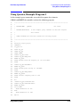
Using Queries, Example Program 3 . . . . . . . . . . . . . . . . . . . . . . . . . . . . . . . . . . . . . . . . . . . .2-81
Generating a CW Signal, Example Program 4 . . . . . . . . . . . . . . . . . . . . . . . . . . . . . . . . . . . .2-84
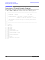
Generating an AC-Coupled External FM Signal, Example Program 5 . . . . . . . . . . . . . . . .2-86
Generating an AC-Coupled Internal FM Signal, Example Program 6 . . . . . . . . . . . . . . . . .2-88
Generating a Step-Swept Signal, Example Program 7 . . . . . . . . . . . . . . . . . . . . . . . . . . . . .2-90
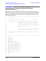
Generating an External DC-Coupled Pulse Modulated Signal, Example Program 8 . . . . .2-92
Saving and Recalling States, Example Program 9 . . . . . . . . . . . . . . . . . . . . . . . . . . . . . . . . .2-94
Reading the Status Byte, Example Program 10 . . . . . . . . . . . . . . . . . . . . . . . . . . . . . . . . . . .2-97
End of Sweep Service Request, Example Program 11 . . . . . . . . . . . . . . . . . . . . . . . . . . . . .2-101
iii
Contents
3. Remote Data Transfer
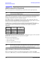
ARB Waveform Data Downloads . . . . . . . . . . . . . . . . . . . . . . . . . . . . . . . . . . . . . . . . . . . . . . . 3-2
User File Data Downloads . . . . . . . . . . . . . . . . . . . . . . . . . . . . . . . . . . . . . . . . . . . . . . . . . . . 3-12
FIR Filter Coefficient Data Downloads . . . . . . . . . . . . . . . . . . . . . . . . . . . . . . . . . . . . . . . . . 3-23
Data Downloads Directly into Pattern RAM . . . . . . . . . . . . . . . . . . . . . . . . . . . . . . . . . . . . . 3-27
Data Transfer Troubleshooting . . . . . . . . . . . . . . . . . . . . . . . . . . . . . . . . . . . . . . . . . . . . . . . 3-33
4. Softkey/Command Cross-Reference
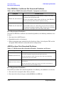
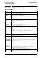
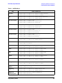
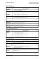
Front Panel Key Versus Command. . . . . . . . . . . . . . . . . . . . . . . . . . . . . . . . . . . . . . . . . . . . . . 4-2
Agilent 8656/57-Compatible Language . . . . . . . . . . . . . . . . . . . . . . . . . . . . . . . . . . . . . . . . . 4-21
iv
ESG Family Signal Generators
1 Preparing for Use
This chapter explains how to set up the equipment for remote programming of the signal
generator, the GPIB and RS-232 capabilities of the signal generator, and provides a
program for an operational check of remote programming functionality. Instruction is also
provided for programming the signal generator using GPIB command statements and the
SCPI language.
Programming Guide
1-1
Preparing for Use
Setting up the Equipment for Remote Operation
ESG Family Signal Generators
Setting up the Equipment for Remote Operation
The signal generator can be remotely controlled using either the general purpose interface
bus (GPIB) or a serial connection to the rear-panel RS-232 auxiliary interface connector.
GPIB Overview
GPIB is a high-performance bus that allows individual instruments and computers to be
combined into integrated test systems. The bus and its associated interface operations are
defined by the IEEE 488.1 standard. The IEEE 488.2 standard defines the interface
capabilities of instruments and controllers in a measurement system, including some
frequently used commands.
NOTE
The functionality provided by GPIB is also available using the rear-panel
RS-232 AUXILIARY INTERFACE. For more information on using this type of
system configuration, see “Serial Interface (RS–232) Overview” on page 1-7.
Commands are sent over the GPIB via a controller’s language system. HP BASIC is the
language used in the programming examples in this book. HP BASIC was selected because
the majority of GPIB computers have BASIC language capability. However, other
languages can also be used. The use of HP BASIC is explained later in this chapter
starting with “Programming the Signal Generator” on page 1-9.
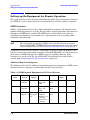
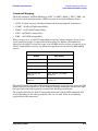
Additional Required Equipment
The following tables list the additional required equipment to implement an GPIB system
interface between a computer or workstation and the signal generator.
Table 1-1 GPIB Required Equipment for PC-Based Systems
Interface
Card
Operating
System
I/O
Library
Languages
HP 82341C
Windows
3.1/95/NT
SICL/VISA
C/C++, Visual
Basic, HP
VEE
ISA/EISA,
16 bit
750
Built-in
HP 82340B
Windows
3.1/95/NT
SICL/VISA
C/C++, Visual
Basic, HP
VEE
ISA/EISA,
16 bit
520
None
HP 82335B
MS-DOS,
Windows 3.1
Command
Library/SI
CL
C/C++,
PASCAL,
BASIC for PC
(including
Visual Basic),
HP VEE
ISA/EISA,
8 bit
355
None
1-2
Backplane
Max I/O
(kB/sec)
Buffering
Programming Guide
ESG Family Signal Generators
Preparing for Use
Setting up the Equipment for Remote Operation
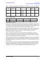
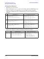
Table 1-2 Required Equipment for HP Series 700 Workstations Running HP-UX
Interface
Card
Operating
System
I/O Library
HP E2071C
HP-UX
SICL/VISA
HP E2070C
HP-UX
SICL/VISA
Languages
Backplane
Max I/O
(kB/sec)
Buffering
ANSI C,
HP VEE,
HP BASIC
EISA
750
Built-in
ANSI C,
HP VEE,
HP BASIC
EISA
230
None
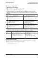
Table 1-3 GPIB Cables
Model
HP 10833A
HP 10833B
HP 10833C
HP 10833D
Length
1 meter
2 meters
4 meters
5 meters
I/O Libraries for GPIB
SCPI (standard commands for programmable instruments) is a popular language used to
communicate with the signal generator. Do not confuse SCPI with SICL and VISA, which
are I/O libraries of functions used by programs that communicate through GPIB. SCPI is
the actual language used to communicate with the signal generator itself.
Agilent Technologies Standard Instrument Control Library (SICL) and Virtual Instrument
Software Architecture (VISA) are I/O libraries used to develop I/O applications for the
GPIB interface. These functions are used in C or BASIC programs to simplify
communication with the signal generator.
SICL is a modular instrument communications library that works with a variety of
computer architectures, I/O interfaces, and operating systems. Applications written in
C/C++ or Visual BASIC using this library can be ported at the source code level from one
system to another without, or with very few, changes.
VISA is an I/O library that can be used to develop I/O applications and instrument drivers
that comply with the VXI “plug & play” standards. Applications and instruments drivers
developed with VISA can execute on VXI “plug & play” system frameworks that have the
VISA I/O layer.
One or both of these libraries are included with the GPIB interface card. SICL/VISA for
Hewlett-Packard Series 700 Controllers (model E2091D) and SICL/VISA for personal
computers (model E2094E) may also be purchased. For additional information on SICL
and VISA, see the user’s guides included with the SICL/VISA software package.
Programming Guide
1-3
Preparing for Use
Setting up the Equipment for Remote Operation
ESG Family Signal Generators
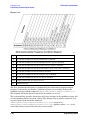
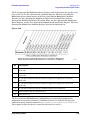
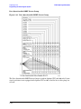
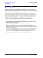
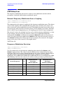
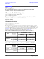
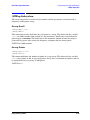
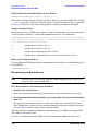
GPIB Interconnecting Cables
The GPIB connector enables you to connect the signal generator to any other instrument
or device on the interface bus. A GPIB connector and cable are shown in Figure 1-1. The
codes next to the connector describe the GPIB electrical capabilities of the signal
generator, using IEEE Std. 488-1978 mnemonics (GPIB, IEEE-488, and IEC-625 are
electrically equivalent, although IEC-625 uses a unique connector).
Figure 1-1 GPIB Connector and Cable
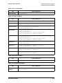
Briefly, the mnemonics translate as follows:
Mnemonic
Capabilities
SH1
Source Handshake
Complete
AH1
Acceptor Handshake
Complete
Talker
Capable of basic talker, serial poll, and unaddressed if
MLA.
Talker, Extended Address
None
Listener
Capable of basic listener, and unaddressed if MTA
LE0
Listener, Extended Address
None
SR1
Service Request
Complete
RL1
Remote Local
Complete
PP0
Parallel Poll
None
DC1
Device Clear
Complete
DT1
Device Trigger
Complete
C0
Controller
None
E2
Identifies electrical tristate drivers
T5
TE0
L3
1-4
Signal Description
Programming Guide
ESG Family Signal Generators
Preparing for Use
Setting up the Equipment for Remote Operation
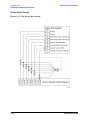
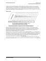
You can connect as many as 14 instruments to the signal generator via GPIB (15 total
instruments in the system). The cables can be interconnected in a star pattern (one central
instrument, with the GPIB cables emanating from that instrument like spokes on a
wheel), or in a linear pattern (like boxcars on a train), or any combination pattern. The
following restrictions apply:
• Each instrument must have a unique GPIB address ranging from 0 through 30
(decimal).
• In a two-instrument system that uses just one GPIB cable, the cable length must not
exceed 4 meters (9.13 ft.) between the two instruments.
• When more than two instruments are connected on the bus, the cable length between
each instrument must not exceed 2 meters (6.5 ft.) per unit.
• The total cable length between all instruments must not exceed 20 meters (65 ft.).
Setting Up the Interface for GPIB Operation
1. Connect a computer and any other peripherals to the signal generator with GPIB
cables.
2. Reset all instruments connected to the bus. If you are not sure how to reset a device,
switch off the line power to the device and then switch the power back on.
3. Check the signal generator’s GPIB address.
Press Utility > GPIB/RS-232 > GPIB Address.
If the address is not 19, press 1 > 9 > Enter.
NOTE
Programming examples in this book assume that the signal generator’s GPIB
address is 19. Modify the examples, if necessary, to correspond to your signal
generator’s address.
4. Check the signal generator’s remote language.
Press Utility > GPIB/RS-232 > Remote Language. The default remote language is SCPI.
If SCPI is not highlighted, press SCPI.
NOTE
Although there are a number of remote languages compatible with other
signal sources, SCPI is the only remote language that can implement all of
the signal generator’s features. Unless you have reason to use one of the other
remote languages (for example, programs previously written for another
signal source that has been replaced by the ESG family signal generator),
choose SCPI to maximize your control of the signal generator’s functionality.
All programming commands in this documentation set are written in SCPI.
Programming Guide
1-5
Preparing for Use
Setting up the Equipment for Remote Operation
ESG Family Signal Generators
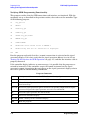
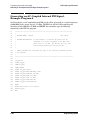
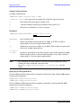
Verifying GPIB Programming Functionality
This program verifies that the GPIB connections and interface are functional. With the
equipment set up as described in the previous section, clear and reset the controller. Type
in the following program:
10
Sig_gen=719
20
ABORT 7
30
LOCAL Sig_gen
40
CLEAR Sig_gen
50
OUTPUT Sig_gen;"*RST"
60
REMOTE Sig_gen
70
CLEAR SCREEN
80
PRINT "The source should now be in REMOTE."
90
PRINT "Verify that the ‘R’ annunciator is displayed"
100
END
Run the program and verify that the R (remote) annunciator is activated on the signal
generator’s display. If it is not, verify that the signal generator address is set to 19 (see
“Setting Up the Interface for GPIB Operation” on page 1-5) and that the interface cable is
properly connected.
If the controller display indicates an error message, it is possible that the program was
entered in incorrectly. If the controller accepts the remote statement but the signal
generator’s remote annunciator does not appear on the signal generator’s display, refer to
the service guide for troubleshooting information.
Program Comments
10:
Sets up a variable to contain the GPIB address of the signal generator.
20:
Aborts any bus activity and return the GPIB interfaces to their reset states.
30:
Places the signal generator into LOCAL mode to cancel any local lockouts that may
have been set up.
40 to 50:
Resets the signal generator’s parser and clears any pending output from the signal
generator. Prepares the signal generator to receive new commands.
60:
Places the signal generator into remote mode.
70:
Clears the controller’s display.
80 to 90:
Prints a message to the controller’s display.
100:
Ends the program.
1-6
Programming Guide
ESG Family Signal Generators
Preparing for Use
Setting up the Equipment for Remote Operation
Serial Interface (RS–232) Overview
You can also control the signal generator using the rear-panel serial RS-232 serial port
(labeled AUXILIARY INTERFACE). All of the functionality provided by GPIB is available
using the rear-panel serial interface, except for indefinite blocks, serial polling, GET,
non-SCPI remote languages, and remote mode.
Commands are sent over the serial interface via a controller’s language system. HP BASIC
is the language used in the programming examples in this book. BASIC was selected
because the majority of GPIB computers have BASIC language capability, but other
languages can also be used. For more detail on using HP Basic, see “Programming the
Signal Generator” on page 1-9. For information regarding RS-232 operating parameters
such as handshake, baud rate, character format, and parity, see “Overview of Serial
Interface (RS-232) Programming” on page 1-10.
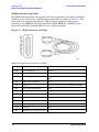
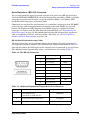
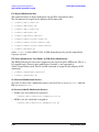
RS-232 Serial Interconnecting Cables
The signal generator’s serial connector enables you to connect the signal generator to a
serial port on a personal computer. The connector’s pin configuration shown in Table 1-4.
Only one instrument per RS-232 port on the computer may be connected at any given time.
The additional items required when using a serial interface are listed in Table 1-5.
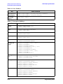
Table 1-4. The RS-232 Connector
Pin Number
Signal Description
Signal Name
1
No Connection
2
Receive Data
RECV
3
Transmit Data
XMIT
4
+5V
5
Ground, 0V
6
No Connection
7
Request to Send
RTS
8
Clear to Send
CTS
9
No Connection
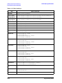
Table 1-5. Additional Equipment Required for Serial Interface
Quantity
Description
Agilent Part Number
1
Serial RS-232 cable
9-pin (male) to 9-pin (female)
8120-6188
1
RS-232 null modem (male-male)1
5158-6639
1
Serial RS-232 adapter (female-female)
1252-7825
1.Ensure proper pin connections between computer and signal generator.
Programming Guide
1-7
Preparing for Use
Setting up the Equipment for Remote Operation
ESG Family Signal Generators
Connecting the Interface
1. Attach the male end of the RS-232 cable to the signal generator’s rear-panel
AUXILIARY INTERFACE connector.
2. Attach the female end of the RS-232 cable to the null modem.
3. Using a 5-mm nut driver, remove both standoffs from the female-to-female adapter.
4. Connect one end of the modified adapter to the null modem and the other end to the
selected port on the computer.
• For personal computers, make the connection to the COM2 RS-232 port. COM1 is
acceptable if available.
• For UNIX workstations, connect to the /dev/tty00 port. Alternatively, /dev/tty01 may
be used if it is available.
Configuring the Interface
1. Set the signal generator’s baud rate.
Press Utility > GPIB/RS-232 > RS-232 Baud Rate. The default RS-232 baud rate is 19200.
Use baud rates 19200 or lower only. Press the appropriate softkey to adjust the signal
generator’s baud rate to the baud rate of your personal computer or UNIX workstation.
2. Set the signal generator’s handshake.
Press Utility > GPIB/RS-232 > RS-232 Pace. To determine the hardware operating
parameters, you need to know whether DSR (data set ready) and CTS (clear to send) are
active during communication with the controller, and the baud rate expected by the
controller. Set the signal generator’s handshake accordingly.
3. Set the signal generator’s RS-232 echo.
Press Utility > GPIB/RS-232 > RS-232 Echo Off On to the desired operating state for your
configuration.
4. Set the signal generator’s remote language.
Press Utility > GPIB/RS-232 > Remote Language. The only remote language supported by
RS-232 is SCPI (standard commands for programmable instruments).
If SCPI is not highlighted, press SCPI to select it.
Verifying the RS-232 System Interface
The following command verifies that the serial interface functions. With the equipment set
up as described in the previous sections, clear and reset the controller. Execute the
following command: OUTPUT "*IDN?"
The signal generator should return a string similar to the following, depending on model:
<instrument model name and number>, US37040098 B.03.00
If not, verify that the RS-232 parameters are set correctly (see “Setting Up the Interface
for GPIB Operation” on page 1-5) and that the interface cable is properly connected.
1-8
Programming Guide
ESG Family Signal Generators
Preparing for Use
Programming the Signal Generator
Programming the Signal Generator
The signal generator can be controlled entirely by a computer (although the line power
switch must be operated manually). Several functions are possible only by remote control.
Computer programming procedures for the signal generator involve selecting a GPIB
command statement and then adding the specific programming codes (SCPI or
8656/67-compatible) to that statement to achieve the desired operating conditions. The
programming codes can be categorized into two groups: those that mimic front panel
keystrokes, and those that are unique and have no front panel equivalent.
In the programming explanations that follow, specific examples are included that are
written in a generic dialect of the HP BASIC language. HP BASIC was selected because
the majority of GPIB computers have HP BASIC language capability. However, other
languages can be used as well.
Data Transfers Between Computer and Peripheral
Five statements are used to transfer information between a desktop computer and the
interface card:
• The OUTPUT statement sends data to the interface which, in turn, sends the
information to the peripheral device.
• The ENTER statement inputs data from the interface card after the interface has
received it from the peripheral device.
• The STATUS statement is used to monitor the interface and obtain information about
interface operation such as buffer status, detected errors, and interrupt enable status.
• The CONTROL statement is used to control interface operation and defines such
parameters as baud rate, character format, or parity.
• The TRANSFER statement is used to input or output data from/to the interface and, in
turn, from/to the peripheral device.
Since the interface has no on-board processor, ENTER and OUTPUT statements cause the
computer to wait until the ENTER or OUTPUT operation is complete before continuing to
the next line. For OUTPUT statements, this means that the computer waits until the last
bit of the last character has been sent over the serial line before continuing with the next
program statement.
Programming Guide
1-9
Preparing for Use
Overview of Serial Interface (RS-232) Programming
ESG Family Signal Generators
Overview of Serial Interface (RS-232) Programming
Serial interface programming techniques are similar to most general I/O applications. The
interface card is initialized by use of CONTROL statements; STATUS statements evaluate
its readiness for use. Data is transferred between the desktop computer and a peripheral
device by OUTPUT and ENTER statements.
Due to the asynchronous nature of serial I/O operations, special care must be exercised to
ensure that data is not lost by sending to another device before the device is ready to
receive. Modem line handshaking can be used to help solve this problem. These and other
topics are discussed in greater detail elsewhere in this chapter.
Determining Operating Parameters
Before you can successfully transfer information to a device, you must match the operating
characteristics of the interface to the corresponding characteristics of the peripheral
device. This includes matching signal lines and their functions as well as matching the
character format for both devices.
Handshake and Baud Rate
To determine hardware operating parameters, you need to know the answer for each of the
following questions about the peripheral device:
• Which of the following signal and control lines are actively used during communication
with the peripheral?
— Data Set Ready (DSR)
— Clear to Send (CTS)
• What baud rate (line speed) is expected by the peripheral?
Character Format Parameters
To define the character format, you must know the requirements of the peripheral device
for the following parameters:
• Character Length: Eight data bits are used for each character, excluding start, stop, and
parity bits.
• Parity Enable: Parity is disabled (absent) for each character.
• Stop Bits: One stop bit is included with each character.
1-10
Programming Guide
ESG Family Signal Generators
Preparing for Use
Overview of Serial Interface (RS-232) Programming
Serial Configuration for BASIC/UX
There is no capability in BASIC/UX for reading the hardware bit settings on either the
HP 98626 or HP 98644 Serial Interface cards. Therefore, BASIC/UX provides two methods
for configuring modem control options:
• The stty command from the HP-UX environment.
• The keyword CONTROL and registers directly related to the modem control options.
Of the two methods mentioned above, the best one to use while in the HP-UX environment
is the stty command. The reason for this is any modem control options set by using the
keyword CONTROL are lost when you leave BASIC/UX. However, if you prefer to change
these options while in the BASIC/UX environment, then read the subsequent section
“Using Program Control to Override Defaults” on page 1-12.
This section deals with the first method mentioned above which is the use of the stty
command from the HP-UX environment.
Defaults for the Serial Interface
When HP-UX is being booted up, the defaults for all serial interfaces are:
Baud Rate
300
Bits per character
8
Parity
Off
Stop bits
1
The above values are used by BASIC/UX as defaults, unless configured as explained in the
next section.
Some common serial interface configuration settings are:
Baud Rate to
9600
Bits per character to
8
Parity to
Odd and disabled
Stop bits to
1
Programming Guide
1-11
Preparing for Use
Overview of Serial Interface (RS-232) Programming
ESG Family Signal Generators
Configuring a Serial Interface for BASIC/UX
To configure your serial interface with the values mentioned in the previous section, you
can execute the following HP-UX command before entering BASIC/UX:
/bin/stty 9600 cs8 -cstopb < /dev/rmb/serialnn
where:
9600 is the baud rate. The following are baud rates you can use with the stty command:
300
1200
2400
4800
9600
19 200
cs8 is the number of bits per character. For this signal generator, the number of bits per
character is 8.
-cstopb causes one stop bit per character to be used.
< /dev/rmb/serialnn assigns the stty options to the serial interface located at select code
number nn.
For more information on stty options, see the HP-UX Language Reference.
Using Program Control to Override Defaults
You can override some of the interface default configuration options by use of CONTROL
statements. This not only enables you to guarantee certain parameters, but also provides a
means for changing selected parameters in the course of a running program.
Interface Reset
Whenever an interface is connected to a modem that may still be connected to a
telecommunications link from a previous session, it is good programming practice to reset
the interface to force the modem to disconnect, unless the status of the link and remote
connection are known. When the interface is connected to a line printer or similar
peripheral, resetting the interface is usually unnecessary unless an error condition
requires it.
100 CONTROL Sc,0;1
! Resets Interface.
When the interface is reset by use of a CONTROL statement to CONTROL Register 0 with
a non-zero value, the interface is restored to the BASIC/UX power-up condition whether or
not it is the same as the current default switch configuration. If you are not sure of the
present settings, or if your application requires changing the configuration during program
operation, you can use CONTROL statements to configure the interface. An example of
where this may be necessary is when several peripherals share a single interface through a
manually operated RS-232 switch such as those used to connect multiple terminals to a
single computer port, or a single terminal to multiple computers.
1-12
Programming Guide
ESG Family Signal Generators
Preparing for Use
Overview of Serial Interface (RS-232) Programming
Selecting the Baud Rate
In order to successfully transfer information between the interface card and a peripheral,
the interface and peripheral must be set to the same baud rate. A CONTROL statement to
register 3 (or 13 with 98644 interfaces) can be used to set the interface baud rate to any
one of the following values:
300
1200
2400
4800
9600
19 200
For example, to select a baud rate of 9600, the following program statement is used:
1190 CONTROL Sc,3;9600
Use of values other than those shown may result in incorrect operation.
To verify the current baud rate setting, use a STATUS statement addressed to register 3.
All rates are in baud (bits/second).
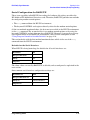
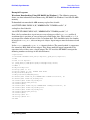
Setting Character Format and Parity
CONTROL Register 4 overrides the Line Control switches that control parity and
character format. All bits in this table correspond to equivalent switch settings on the
HP 98626 and HP 98644 serial interface cards. A 1 is the same as set. To determine the
value sent to the register, add the appropriate values selected from the following table.
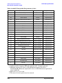
Table 1-6 Character Format and Parity Settings Handshake
Handshake
(Bits 7 & 6)
01 Xon/Xoff
Bidirectional 11
Handshake Disabled
Parity Enable
(Bit 3)
0 Disabled
Stop Bits
(Bit 2)
0 One stop bit
Character Length
(Bits 1 & 0)
11 Eight bits/char
For example, to configure a character format of 8 bits per character, one stop bit, and
disabled parity, with XON/XOFF; use the following CONTROL statement:
1200 CONTROL Sc,4;IVAL(“10011”,2)
-or1200 CONTROL Sc,4;19
Programming Guide
1-13
Preparing for Use
Transferring Data
ESG Family Signal Generators
Transferring Data
The serial interface card is designed for relatively simple serial I/O operations. It is not
intended for sophisticated applications that use ON INTR statements to service the
interface.
Entering and Outputting Data
When the interface is properly configured, either by use of default switches or CONTROL
statements, you are ready to begin data transfers. OUTPUT statements are used to send
information to the peripheral; ENTER statements to input information from the external
device.
• OUTPUT 20;”String data”,Numeric_var,Etc
• ENTER 20;String_var$,Numeric_var,Etc
Any valid OUTPUT or ENTER statement and variables list may be used, but you must be
sure that the data format is compatible with the peripheral device. For example,
non-ASCII data sent to an ASCII line printer may result in unexpected behavior.
Various other I/O statements can be used in addition to OUTPUT and ENTER, depending
on the situation. For example, the LIST statement can be used to list programs to an
RS-232 line printer -- provided the interface is properly configured before the operation
begins.
Outputting Data
To send data to a peripheral, use OUTPUT, OUTPUT USING, or any other similar or
equivalent construct. Suppression of end-of-line delimiters and other formatting
capabilities are identical to normal operation in general I/O applications. The OUTPUT
statement hangs the computer until the last bit of the last character in the statement
variable list is transmitted by the interface. When the output operation is complete, the
computer then continues to the next line in the program.
Entering Data
To input data from a peripheral, use ENTER, ENTER USING, or an equivalent statement.
Inclusion or elimination of end-of-line delimiters and other information is determined by
the formatting specified in the ENTER statement. The ENTER statement hangs the
computer until the input variables list is satisfied. To minimize the risk of waiting for
another variable that isn’t coming, you may prefer to specify only one variable for each
ENTER statement, and analyze the result before starting the next input operation.
Be sure that the peripheral is not transmitting data to the interface while no ENTER is in
progress. Otherwise, data may be lost because the card provides buffering for only one
character. Also, interrupts from other I/O devices, or operator inputs to the computer
keyboard can cause delay in computer service to the interface that result in buffer overrun
at higher baud rates.
1-14
Programming Guide
ESG Family Signal Generators
Preparing for Use
Transferring Data
Modem Line Handshaking
Modem line handshaking, when used, is performed automatically by the computer as part
of the OUTPUT or ENTER operation. If the modem line states have not been latched in a
fixed state by Control Register, the following sequence of events is executed automatically
during each OUTPUT or ENTER operation:
For OUTPUT operations:
1. Set Data Terminal Ready and Request-to-Send modem lines to active state.
2. Check Data Set Ready and Clear-to-Send modem lines to be sure they are active.
3. Send information to the interface and then to the peripheral.
4. After data transfer is complete, clear Data Terminal Ready and Request-to-Send
signals.
For ENTER operations:
1. Set Data Terminal Ready line to active state. Leave Request-to-Send inactive.
2. Check Data Set Ready and Data Carrier Detect modem lines to be sure they are active.
3. Input information from the interface as it is received from the peripheral.
4. After the input operation is complete, clear the Data Terminal Ready signal.
After a given OUTPUT or ENTER operation is completed, the program continues
execution on the next line.
Control Register 5 can be used to force selected modem control lines to their active states.
The Data Rate Select line is set or cleared by bit 2. Request-to-send and Data Terminal
Ready are held in their active states when bits 1 and 0 are true, respectively. If bits 1 or 0
are false, the corresponding modem line is toggled during OUTPUT or ENTER as
explained previously.
Programming Guide
1-15
Preparing for Use
Transferring Data
ESG Family Signal Generators
Incoming Data Error Detection and Handling (BASIC/WS only)
The serial interface card can generate several errors that are caused when certain
conditions are encountered while receiving data from the peripheral device. The UART
detects a given error condition. The card then generates a pending error to BASIC. Errors
can be generated by any of the following conditions:
• Parity error. The parity bit on an incoming character does not match the parity expected
by the receiver. This condition is most commonly caused by line noise.
• Framing error. Start and stop bits do not match the timing expectations of the receiver.
This can occur when line noise causes the receiver to miss the start bit or obscures the
stop bits.
• Overrun error. Incoming data buffer overrun caused a loss of one or more data
characters. This is usually caused when data is received by the interface, but no
ENTER statement has been activated to input the information.
• Break received. A BREAK was sent to the interface by the peripheral device. The
desktop computer program must be able to properly interpret the meaning of a break
and take appropriate action.
All UART status errors are generated by incoming data, never by outbound data. When a
UART error occurs, the corresponding bit of Status Register 10 is set, and a pending error
(ERROR 167: Interface status error) is sent to BASIC. BASIC processes the error according
to the following rules:
• If an ENTER is in progress, the error is handled immediately as part of the ENTER
process. An active ON ERROR causes the error trap to be executed. If no ON ERROR is
active, the error is fatal and causes the program to terminate.
• If an OUTPUT is in progress, or if there is no current activity between the computer
and interface, the error is flagged, but nothing is done by BASIC until an ENTER
statement is encountered. When the computer begins execution of the ENTER
statement, if an ON ERROR is active, the error trap is executed. If there is no active ON
ERROR for that select code, the fatal ERROR 167 causes the BASIC program to
terminate.
• If a STATUS statement is executed to Status Register 10 before an ENTER statement
is encountered for that select code, the pending BASIC error is cleared, and the program
continues as if no error had been generated.
Note that the above UART status errors cannot be detected using BASIC/UX.
1-16
Programming Guide
ESG Family Signal Generators
Preparing for Use
GPIB Instrument Nomenclature
GPIB Instrument Nomenclature
An instrument that is part of an GPIB network is categorized as a listener, talker, or
controller, depending on its current function in the network.
Listener
A listener is a device capable of receiving data or commands from other
instruments. Any number of instruments in the GPIB network can be
listeners simultaneously.
Talker
A talker is a device capable of transmitting data or commands to other
instruments. To avoid confusion, an GPIB system allows only one device at
a time to be an active talker.
Controller
A controller is an instrument, typically a computer, capable of managing
the various GPIB activities. Only one device at a time can be an active
controller.
Programming Guide
1-17
Preparing for Use
GPIB Command Statements
ESG Family Signal Generators
GPIB Command Statements
Command statements form the nucleus of GPIB programming; they are understood by all
instruments in the network. When combined with the programming language codes, they
provide all management and data communication instructions for the system.
An explanation of the fundamental command statements follows. Some computers may use
a slightly different terminology, or support an extended or enhanced version of these
commands. Use the following explanations as a starting point and refer to the HP BASIC
language reference manual, the I/O programming guide, and the GPIB manual for the
computer you are using.
Syntax drawings accompany each statement. All items enclosed by a circle or oval are
computer-specific terms that must be entered exactly as described; items enclosed in a
rectangular box are names of parameters used in the statement; and the arrows indicate a
path that generates a valid combination of statement elements.
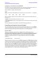
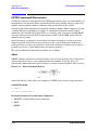
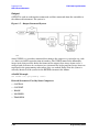
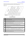
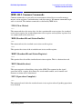
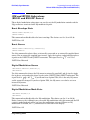
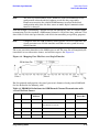
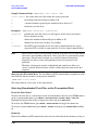
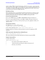
The seven fundamental command statements are as follows:
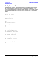
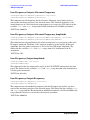
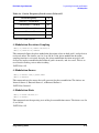
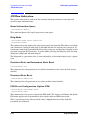
Abort
ABORT abruptly terminates all listener/talker activity on the interface bus, and prepares
all instruments to receive a new command from the controller. Typically, this is an
initialization command used to place the bus in a known starting condition. The syntax is:
Figure 1-2. Abort Command Syntax
where the interface select code is the computer’s GPIB I/O port, which is typically port 7.
A BASIC Example
10 ABORT 7
100 IF V>20 THEN ABORT 7
Related Statements Used by Some Computers
• ABORTIO (used by HP-80 series computers)
• HALT
• RESET
1-18
Programming Guide
ESG Family Signal Generators
Preparing for Use
GPIB Command Statements
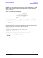
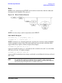
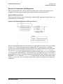
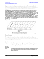
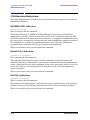
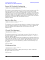
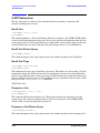
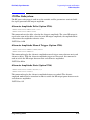
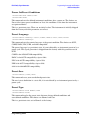
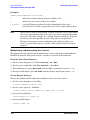
Remote
REMOTE causes an instrument to change from local control to remote control. In remote
control, the front panel keys are disabled except for the Local key and the line power
switch. The syntax is:
Figure 1-3. Remote Command Syntax
where the device selector is the address of the instrument appended to the GPIB port
number. Typically, the GPIB port number is 7 and the default address for the signal
generator is 19, so the device selector is 719.
Some BASIC Examples
10 REMOTE 7
which prepares all GPIB instruments for remote operation (although nothing appears to
happen to the instruments until they are addressed to talk), or
10 REMOTE 719
which affects the GPIB instrument located at address 19, or
10 REMOTE 719, 721, 726, 715
which affects four instruments that have addresses 19, 21, 26, and 15.
Related Statements Used by Some Computers
• RESUME
Programming Guide
1-19
Preparing for Use
GPIB Command Statements
ESG Family Signal Generators
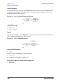
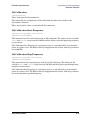
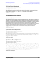
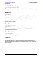
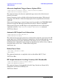
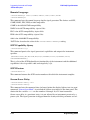
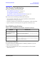
Local Lockout
LOCAL LOCKOUT can be used with REMOTE to disable the front panel Local key. With
the Local key disabled, only the controller (or a hard reset by the line power switch) can
restore local control. The syntax is:
Figure 1-4. Local Lockout Command Syntax
A BASIC Example
10 REMOTE 719
20 LOCAL LOCKOUT 7
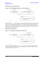
Local
LOCAL is the complement to REMOTE, causing an instrument to return to local control
with a fully enabled front panel. The syntax is:
Figure 1-5. Local Command Syntax
Some BASIC Examples
10 LOCAL 7
which affects all instruments in the network, or
10 LOCAL 719
for an addressed instrument (address 19).
Related Statements Used by Some Computers
• RESUME
1-20
Programming Guide
ESG Family Signal Generators
Preparing for Use
GPIB Command Statements
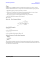
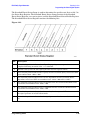
Clear
CLEAR causes all GPIB instruments, or addressed instruments, to assume a cleared
condition. The definition of clear is unique for each instrument. For the signal generator:
1. All pending output-parameter operations are halted.
2. The parser (the software that interprets the programming codes) is reset and now
expects to receive the first character of a programming code.
3. Any sweep in progress is aborted and continuous sweep is turned off.
4. Any I/Q calibration in progress will be aborted.
The syntax is:
Figure 1-6. Clear Command Syntax
Some BASIC Examples
10 CLEAR 7
to clear all GPIB instruments, or
10 CLEAR 719
to clear an addressed instrument (address 19)
Related Statements Used by Some Computers
• RESET
• CONTROL
• SEND
The preceding statements are primarily management commands that do not incorporate
programming codes. The following two statements do incorporate programming codes and
are used for data communication.
Programming Guide
1-21
Preparing for Use
GPIB Command Statements
ESG Family Signal Generators
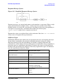
Output
OUTPUT is used to send function commands and data commands from the controller to
the addressed instrument. The syntax is:
Figure 1-7. Output Command Syntax
where USING is a secondary command that formats the output in a particular way, such
as a binary or ASCII representation of numbers. The USING command is followed by
image items that precisely define the format of the output; these image items can be a
string of code characters or a reference to a statement line in the program. Image items are
explained in the programming codes where they are needed. Notice that this syntax is
virtually identical to the syntax for the ENTER statement that follows.
A BASIC Example
100 OUTPUT 719; "programming codes"
Related Statements Used by Some Computers
• CONTROL
• CONVERT
• IMAGE
• IOBUFFER
• TRANSFER
1-22
Programming Guide
ESG Family Signal Generators
Preparing for Use
GPIB Command Statements
Enter
ENTER is the complement of OUTPUT and is used to transfer data from the addressed
instrument to the controller. The syntax is:
Figure 1-8. Enter Command Syntax
ENTER is nearly always used in conjunction with OUTPUT.
Some BASIC Examples
100 OUTPUT 719, "...programming codes..."
110 ENTER 719; "...response data..."
ENTER statements are commonly formatted, requiring the secondary command USING
and the appropriate image items. The most-used image items involve end-of-line (EOI)
suppression, binary inputs, and literal inputs. For example:
100 ENTER 719 USING "#, B"; A, B, C
suppresses the EOI sequence (#), and indicates that variables A, B, and C are to be filled
with binary (B) data. In another example:
100 ENTER 719 USING "#, 123A"; A$
suppresses EOI and indicates that string variable A$ is to be filled with 123 bytes of literal
data (123A).
NOTE
Be careful when using byte-counting image specifiers. If the requested
number of bytes does not match the actual number available, data might be
lost or the program might enter an endless wait state.
Programming Guide
1-23
Preparing for Use
GPIB Command Statements
ESG Family Signal Generators
The suppression of the EOI sequence is frequently necessary to prevent a premature
termination of the data input. When not specified, the typical EOI termination occurs
when an ASCII LF (line feed) is received. However the LF bit pattern could coincidentally
occur randomly in a long string of binary data, where it might cause a false termination.
Also the bit patterns for the ASCII CR (carriage return), comma, or semicolon might cause
a false termination. Suppression of the EOI causes the computer to accept all bit patterns
as data, not commands, and relies on the GPIB EOI (end or identify) line for correct
end-of-data termination.
Related Statements Used by Some Computers
• CONVERT
• IMAGE
• IOBUFFER
• ON TIMEOUT
• SET TIMEOUT
• TRANSFER
1-24
Programming Guide
ESG Family Signal Generators
Preparing for Use
Getting Started with SCPI
Getting Started with SCPI
This section describes the use of the Standard Commands for Programmable Instruments
language (SCPI). This section explains how to use SCPI commands in general. For a list of
the specific SCPI commands available in the signal generator, refer to Chapter 2 and
Chapter 3.
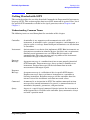
Understanding Common Terms
The following terms are used throughout the remainder of this chapter.
Controller
A controller is any computer used to communicate with a SCPI
instrument. A controller can be a personal computer, a minicomputer, or a
plug-in card in a card cage. Some intelligent instruments can also function
as controllers.
Instrument
An instrument is any device that implements SCPI. Most instruments are
electronic measurement or stimulus devices, but this is not a requirement.
Similarly, most instruments use an GPIB or RS-232 interface for
communication. The same concepts apply regardless of the instrument
function or the type of interface used.
Program
Message
Response
Message
A program message is a combination of one or more properly formatted
SCPI commands. Program messages always go from a controller to an
instrument. Program messages tell the instrument how to make
measurements and output signals.
A response message is a collection of data in specific SCPI formats.
Response messages always go from an instrument to a controller or
listening instrument. Response messages tell the controller about the
internal state of the instrument and about measured values.
Command
A command is an instruction in SCPI. You combine commands to form
messages that control instruments. In general, a command consists of
mnemonics (keywords), parameters, and punctuation.
Query
A query is a special type of command. Queries instruct the instrument to
make response data available to the controller. Query mnemonics always
end with a question mark.
Programming Guide
1-25
Preparing for Use
Getting Started with SCPI
ESG Family Signal Generators
Standard Notation
This section uses several forms of notation that have specific meaning:
Command
Mnemonics
Angle
Brackets
Many commands have both a long and a short form and you must use
either one or the other (SCPI does not accept a combination of the two).
Consider the FREQuency command, for example. The short form is FREQ
and the long form is FREQUENCY. This notation type is a shorthand to
document both the long and short form of commands. SCPI is not case
sensitive, so fREquEnCy is just as valid as FREQUENCY, but FREQ and
FREQUENCY are the only valid forms of the FREQuency command.
Angle brackets indicate that the word or words enclosed represent
something other than themselves. For example, <new line> represents
the ASCII character with the decimal value 10. Similarly, <END> means
that EOI is asserted on the GPIB interface. Words in angle brackets have
much more rigidly defined meaning than words shown in ordinary text.
For example, this section uses the word “message” to talk about messages
generally. But the bracketed words <program message> indicate a
precisely defined element of SCPI. If you need them, you can find the exact
definitions of words such as <program message> in a syntax diagram.
How to Use Examples
Programming with SCPI requires knowledge of two languages. You must know the
programming language of your controller (BASIC, C, Pascal) as well as the language of
your instrument (SCPI). The semantic requirements of your controller’s language
determine how the SCPI commands and responses are handled in your application.
Command Examples
Command examples look like this:
:FREQuency:CW?
This example tells you to put the string :FREQuency:CW? in the output statement
appropriate to your application programming language. If you encounter problems, study
the details of how the output statement handles message terminators such as <new line>.
If you are using simple OUTPUT statements in HP BASIC, this is taken care of for you. In
HP BASIC, you type:
OUTPUT 719":FREQuency:CW?"
Command examples do not show message terminators because they are used at the end of
every program message. See “Details of Commands and Responses” on page 1-35 for more
information about message terminators.
1-26
Programming Guide
ESG Family Signal Generators
Preparing for Use
Getting Started with SCPI
Response Examples
Response examples look like this:
3.000000000000E+009
These are the characters you would read from an instrument after sending a query
command. To actually pull them from the instrument into the controller, use the input
statement appropriate to your application programming language. If you have problems,
study the details of how the input statement operates. In particular, investigate how the
input statement handles punctuation characters such as the comma and the semicolon and
how it handles <new line> and EOI. To enter the previous response in HP BASIC you
type:
ENTER 719;CW_frequency
Response examples do not show response message terminators because they are always
<new line> <END>. These terminators are typically automatically handled by the input
statement. See “Details of Commands and Responses” on page 1-35 for more information
about terminators.
Program and Response Messages
To understand how your instrument and controller communicate using SCPI, you must
understand the concepts of program and response messages. Program messages are the
formatted data sent from the controller to the instrument. Conversely, response messages
are the formatted data sent from the instrument to the controller. Program messages
contain one or more commands, and response messages contain one or more responses.
The controller may send commands at any time, but the instrument sends responses only
when specifically instructed to do so. The special type of command used to instruct the
instrument to send a response message is the query. All query mnemonics end with a
question mark. Queries return either measured values or internal instrument settings.
Any internal setting that can be programmed with SCPI can also be queried.
Forgiving Listening and Precise Talking
SCPI uses the concept of forgiving listening and precise talking outlined in IEEE 488.2.
Forgiving listening means that instruments are very flexible in accepting various
command and parameter formats. For example, the signal generator accepts either
:POWer:ALC[:STATe] ON or :POWer:ALC[:STATe] 1 to turn on the source’s RF output.
Precise talking means that the response format for a particular query is always the same.
For example, if you query the power state when it is on (using :POWer:ALC[:STATe]?), the
response is always 1, regardless of whether you previously sent :POWer:ALC[:STATe] 1 or
:POWer:ALC[:STATe] ON.
Programming Guide
1-27
Preparing for Use
Getting Started with SCPI
ESG Family Signal Generators
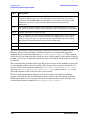
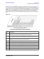
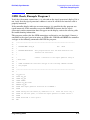
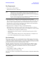
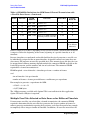
Types of Commands
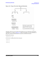
Commands can be separated into two groups, common commands and subsystem
commands.
Common commands are generally not measurement related. They are used to manage
macros, status registers, synchronization, and data storage. Common commands are easy
to recognize because they all begin with an asterisk, such as *IDN?, *OPC, and *RST.
Common commands are defined by IEEE 488.2.
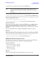
Subsystem commands include all measurement functions and some general purpose
functions. Subsystem commands are distinguished by the colon used between keywords, as
in :FREQuency:CW?. Each command subsystem is a set of commands that roughly
corresponds to a functional block inside the instrument. For example, the :POWer
subsystem contains commands for power generation, while the :STATus subsystem
contains commands for accessing status registers.
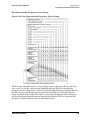
Figure 1-9. SCPI Command Types
The remaining paragraphs in this subsection discuss subsystem commands in more detail.
Remember, some commands are implemented in one instrument and not in another,
depending on its measurement function.
1-28
Programming Guide
ESG Family Signal Generators
Preparing for Use
Getting Started with SCPI
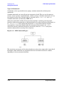
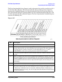
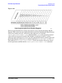
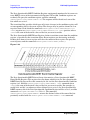
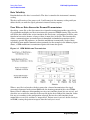
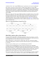
Subsystem Command Trees
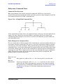
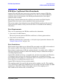
Command Tree Structure
Most programming tasks involve subsystem commands. SCPI uses a hierarchical
structure for subsystem commands similar to the file systems on most computers. In SCPI,
this command structure is called a command tree.
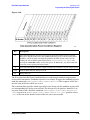
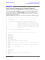
Figure 1-10. A Simplified Command Tree
In the command tree shown above, the command closest to the top is the root command, or
simply “the root.” Notice that you must follow a particular path to reach lower level
subcommands. For example, if you wish to access the GG command, you must follow the
path AA to BB to GG.
Paths Through the Command Tree
To access commands in different paths in the command tree, you must understand how an
instrument interprets commands. The parser, a part of the instrument firmware, decodes
each message sent to the instrument. The parser breaks up the message into component
commands using a set of rules to determine the command tree path used. The parser keeps
track of the current path: the level in the command tree where it expects to find the next
command you send. This is important because the same keyword may appear in different
paths. The particular path you use determines how the keyword is interpreted. The
following rules are used by the parser:
Power On and
Reset
After power is cycled or after *RST, the current path is set to the root.
Message
Terminators
A message terminator, such as a <new line> character, sets the current
path to the root. Many programming languages have output statements
that send message terminators automatically. See “Details of Commands
and Responses” on page 1-35 for more information about message
terminators.
Programming Guide
1-29
Preparing for Use
Getting Started with SCPI
ESG Family Signal Generators
Colon
When a colon is placed between two command mnemonics, it moves the
current path down one level in the command tree. For example, the colon
in MEAS:VOLT specifies that VOLT is one level below MEAS. When the colon is
the first character of a command, it specifies that the next command
mnemonic is a root level command. For example, the colon in :INIT
specifies that INIT is a root level command.
Semicolon
A semicolon separates two commands in the same message without
changing the current path.
White Space
White space characters, such as <tab> and <space>, are generally ignored.
There are two important exceptions. White space inside a keyword, such
as:
:FREQ uency
is not allowed. You must use white space to separate parameters from
commands. For example, the <space> between LEVel and 6.2 in the
command :POWer:LEVel 6.2 is mandatory. White space does not affect
the current path.
Commas
Common
Commands
1-30
If a command requires more than one parameter, you must separate
adjacent parameters using a comma. Commas do not affect the current
path.
Common commands, such as *RST, are not part of any subsystem. An
instrument interprets them in the same way, regardless of the current
path setting.
Programming Guide
ESG Family Signal Generators
Preparing for Use
Getting Started with SCPI
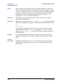
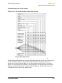
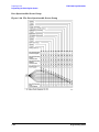
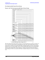
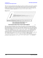
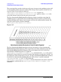
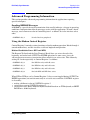
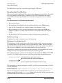
Figure 1-11. Proper Use of the Colon and Semicolon
Examples of how to use the colon and semicolon to navigate efficiently through the
command tree are shown in Figure 1-11. Notice how proper use of the semicolon can
reduce the amount of information that must be sent over the interface.
Sending this message:
:AA:BB:EE; FF; GG
is the same as sending these three messages:
:AA:BB:EE
:AA:BB:FF
:AA:BB:GG
Programming Guide
1-31
Preparing for Use
Getting Started with SCPI
ESG Family Signal Generators
More About Commands
Query and Event Commands
You can query any value that you can set. For example, the presence of the signal
generator FREQuency:OFFSet command implies that a FREQuency:OFFSet? also exists. If
you see a command ending with a question mark, it is a query-only command. Some
commands are events and cannot be queried. An event has no corresponding setting if it
causes something to happen inside the instrument at a particular instant.
Implied Commands
Implied commands appear in square brackets. If you send a subcommand immediately
preceding an implied command, but do not send the implied command, the instrument
assumes you intend to use the implied command and behaves just as if you had sent it.
Notice that this means that the instrument expects you to include any parameters
required by the implied command. The following example illustrates equivalent ways to
program the signal generator using explicit and implied commands.
Example signal generator commands with and without an implied command:
FREQuency[:CW] 500 MHz
using explicit commands
FREQuency 500 MHz
using implied commands
Optional Parameters
Optional parameter names are enclosed in square brackets. If you do not send a value for
an optional parameter, the instrument chooses a default value. The instrument’s command
dictionary documents the values used for optional parameters.
1-32
Programming Guide
ESG Family Signal Generators
Preparing for Use
Getting Started with SCPI
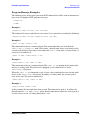
Program Message Examples
The following parts of the signal generator SCPI command set will be used to demonstrate
how to create complete SCPI program messages:
:FREQuency
:POWER
Example 1
“FREQuency:STARt 500 MHz; STOP 1000 MHz”
The command is correct and will not cause errors. It is equivalent to sending the following:
“FREQuency:STARt 500 MHz; FREQuency:STOP 1000 MHz”
Example 2
“POWer 10 DBM; :OFFSet 5 DB”
This command results in a command error. The command makes use of the default
POWer[:LEVel][:IMMediate] node. When using a default node, there is no change to the
current path position. Since there is no command “OFFSet” at the root, an error results. A
correct way to send this is:
“POWer 10 DBM; :POWer:OFFSet 5 DB”
Example 3
“POWer:OFFSet 5 DB; POWer 10 DBM”
This command results in a command error. The POWer 10 DBM portion of the command is
missing a leading colon. The path level is dropped at each colon until it is in the
POWer:OFFSet subsystem.
When the POWer 10 DBM command is sent, it then causes confusion because no such node
occurs in the POWer:OFFSet subsystem. By adding a leading colon, the current path is
reset to the root. The correct command is:
“POWer:OFFSet 5 DB; :POWer 10 DBM”
Example 4
“FREQ 500 MHZ; POWER 4 DBM”
In this example the keyword short form is used. The command is correct. It utilizes the
default nodes of [:CW] and [:LEVEL]. Since default nodes do not affect the current path, it
is not necessary to use a leading colon before POWER.
Programming Guide
1-33
Preparing for Use
Getting Started with SCPI
ESG Family Signal Generators
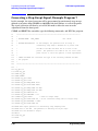
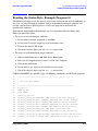
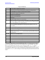
Reading Instrument Errors
When debugging a program, you may want to know if an instrument error has occurred.
The signal generator can display error messages on their front panel displays. If your
system includes an instrument that does not have this capability, you can put the following
code segment in your program to read error messages and print them on the controller’s
display.
10 !
20 ! The rest of your
30 ! variable declarations
40 Assign @box to 719
50 DIM Err_msg$[75]
60 INTEGER Err_num
70 !
80 ! Part of your program
90 ! that generates errors
100 !
110 !
200 REPEAT
210 OUTPUT @Box;":SYST:ERR?"
220 ! Query instrument error
230 ENTER @Box;Err_num,Err_msg$
240 ! Read error #, message
250 PRINT Err_num,Err_msg$
260 ! Print error message
270 UNTIL Err_num = 0
280 ! Repeat until no errors
290 !
300 ! The rest of your program
310 !
1-34
Programming Guide
ESG Family Signal Generators
Preparing for Use
Getting Started with SCPI
Details of Commands and Responses
This section describes the syntax of SCPI commands and responses. It provides many
examples of the data types used for command parameters and response data.
Program Message Syntax
These program messages contain commands combined with appropriate punctuation and
program message terminators.
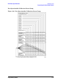
Figure 1-12. Simplified Program Message Syntax
You can send common commands and subsystem commands in the same message as shown
in Figure 1-12. If you send more than one command in the same message, you must
separate them with a semicolon. You must always end a program message with one of the
three program message terminators shown in Figure 1-12. Use <new line>, <END>, or
<new line> <END> as the program message terminator. The word <END> means that EOI
is asserted on the GPIB interface at the same time the preceding data byte is sent. Most
programming languages send these terminators automatically. For example, if you use the
HP BASIC OUTPUT statement, <new line> is automatically sent after your last data byte.
If you are using a PC, you can usually configure the system to send whatever terminator
you specify.
Programming Guide
1-35
Preparing for Use
Getting Started with SCPI
ESG Family Signal Generators
SCPI Subsystem Command Syntax
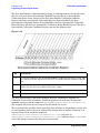
Figure 1-13. SCPI Simplified Subsystem Command Syntax
There must be a <space> between the last command mnemonic and the first parameter in
a subsystem command as shown in Figure 1-13. This is one of the few places in SCPI
where <space> is required. Note that if you send more than one parameter with a single
command, you must separate adjacent parameters with a comma. Parameter types are
explained later in this subsection.
Common Command Syntax
Figure 1-14. Simplified Common Command Syntax
As with subsystem commands, use a <space> to separate a command mnemonic from
subsequent parameters. Separate adjacent parameters with a comma. Parameter types
are explained later in this section.
1-36
Programming Guide
ESG Family Signal Generators
Preparing for Use
Getting Started with SCPI
Response Message Syntax
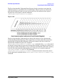
Figure 1-15. Simplified Response Message Syntax
Response messages can contain both commas and semicolons as separators. When a single
query command returns multiple values, a comma separates each data item. When
multiple queries are sent in the same message, the groups of data items corresponding to
each query are separated by a semicolon. For example, the fictitious query
:QUERY1?:QUERY2? might return a response message of:
,;,
Response data types are explained later in this subsection. Note that <new line><END> is
always sent as a response message terminator.
SCPI Data Types
SCPI defines different data formats for use in program messages and response messages.
It does this to accommodate the principle of forgiving listening and precise talking.
Forgiving listening means that instruments are flexible, accepting commands and
parameters in various formats. Precise talking means an instrument always responds to a
particular query in a predefined, rigid format. Parameter data types are designed to be
flexible in the spirit of forgiving listening. Conversely, response data types are defined to
meet the requirements of precise talking.
Parameter Types
Response Data Types
Numeric
Real or Integer
Extended Numeric
Integer
Discrete
Discrete
Boolean
Numeric Boolean
String
String
Block
Definite Length Block (all interfaces)
Indefinite Length Block
(not supported with RS-232)
Non-decimal Numeric
Hexadecimal
Octal
Binary
Programming Guide
1-37
Preparing for Use
Getting Started with SCPI
ESG Family Signal Generators
Each parameter type has one or more corresponding response data types. For example, a
setting that you program using a numeric parameter returns either real or integer
response data when queried. Whether real or integer response data is returned depends on
the instrument used. However, precise talking requires that the response data type be
clearly defined for a particular instrument and query. Chapter 2 contains information
about data types for individual commands.
Parameter Types
Numeric Parameters Numeric parameters are used in both subsystem commands and
common commands. Numeric parameters accept all commonly used decimal
representations of numbers including optional signs, decimal points, and scientific
notation.
If an instrument setting programmed with a numeric parameter can only assume a finite
number of values, the instrument automatically rounds the parameter. For example, if an
instrument has a programmable output impedance of 50 or 75 ohms, and you specified
76.1 for output impedance, the value is rounded to 75. If the instrument setting can only
assume integer values, it automatically rounds the value to an integer. For example
sending *ESE 10.123 is the same as sending *ESE 10.
Examples of numeric parameters:
100
no decimal point required
100.
fractional digits optional
−1.23
leading signs allowed
4.56e<space>3
space allowed after e in exponential
−7.89E−01
use either E or e in exponential
+256
leading + allowed
.5
digits left of decimal point optional
Extended Numeric Parameters Most subsystems use extended numeric parameters to
specify physical quantities. Extended numeric parameters accept all numeric parameter
values and other special values as well. All extended numeric parameters accept MAXimum
and MINimum as values. Other special values, such as UP and DOWN may be available as
documented in Chapter 2. Notice that MINimum and MAXimum can be used to set or query
values. The query forms are useful for determining the range of values allowed for a given
parameter.
In some instruments, extended numeric parameters accept engineering unit suffixes as
part of the parameter value.
Notice that extended numeric parameters are not used for common commands or STATus
subsystem commands.
1-38
Programming Guide
ESG Family Signal Generators
Preparing for Use
Getting Started with SCPI
Examples of extended numeric parameters:
100.
any simple numeric values
−1.23
4.56e<space>3
−7.89E−01
+256
.5
MAX
largest valid setting
MIN
valid setting nearest negative infinity
−100 mV
negative 100 millivolts
Discrete Parameters Use discrete parameters to program settings that have a finite
number of values. Discrete parameters use mnemonics to represent each valid setting.
They have a long and a short form, just like command mnemonics. You can use mixed
upper and lower case letters for discrete parameters.
Examples of discrete parameters used with the TRIG:SOURce subsystem:
BUS
GPIB triggering
IMMediate
immediate trigger
EXTernal
external triggering
Although discrete parameter values look like command keywords, do not confuse the two.
In particular, be sure to use colons and spaces properly. Use a colon to separate command
mnemonics from each other. Use a space to separate parameters from command
mnemonics.
Examples of discrete parameters in commands:
100 OUTPUT @Source;"TRIGger:SOURce BUS"
100 OUTPUT @Source;"TRIGger:SOURce IMMediate"
100 OUTPUT @Source;"TRIGger:SOURce EXTernal"
Programming Guide
1-39
Preparing for Use
Getting Started with SCPI
ESG Family Signal Generators
Boolean Parameters Boolean parameters represent a single binary condition that is
either true or false. There are only four possible representations for a Boolean parameter:
ON
Boolean true, upper/lower case allowed
OFF
Boolean false, upper/lower case allowed
1
Boolean true
0
Boolean false
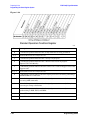
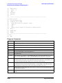
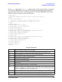
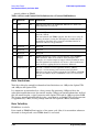
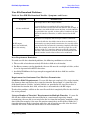
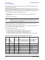
Block Parameters A data block contains the data of primary interest. It may contain
dimensioned data such as DATA(CURVe), or specific sets of data (WAVEform, etc.). At
least one data block is required and multiple data blocks are allowed. The following table
details the data block for a List Pattern data block, used to write pattern lists directly to
the instrument’s baseband generator board:
Bit 0 (1)
data value: 0 or 1 as required for a data bit.
Bit 1 (2)
Always 0
Bit 2 (4)
Burst control: 0 for burst off, 1 for burst on. All data values that require
power out must have this bit on.
Bit 3 (8)
Always 0
Bit 4 (16)
Always 16
Bit 5 (32)
Always 0
Bit 6 (64)
Event 1 control: 0 or 1, as desired on the EVENT1 output.
Bit 7 (128)
Pattern reset: Reset the pattern to start after this entry is processed.
Response Data Types
Real Response Data A large portion of all measurement data are formatted as real
response data. Real response data are decimal numbers in either fixed decimal notation or
scientific notation. Most high-level programming languages that support instrument I/O
handle either decimal or scientific notation transparently.
Examples of real response data:
1.23E+0
−1.0E+2
+1.0E+2
0.5E+0
1.23
−100.0
+100.0
0.5
1-40
Programming Guide
ESG Family Signal Generators
Preparing for Use
Getting Started with SCPI
Integer Response Data Integer response data are decimal representations of integer
values including optional signs. Most status register related queries return integer
response data.
Examples of integer response data:
0
signs are optional
+100
leading + sign allowed
−100
leading sign allowed
256
never any decimal point
Discrete Response Data Discrete response data are similar to discrete parameters. The
main difference is that discrete response data return only the short form of a particular
mnemonic, in all upper case letters.
Examples of discrete response data:
IMM
Immediate
EXT
External
String Response Data String response data are similar to string parameters. The main
difference is that string response data use only double quotes as delimiters, rather than
single quotes. Embedded double quotes may be present in string response data. Embedded
quotes appear as two adjacent double quotes with no characters between them.
Examples of string response data:
“This IS valid”
“SO IS THIS”” “
“I said, ““Hello!”””
Programming Guide
1-41
Preparing for Use
Programming the Status Register System
ESG Family Signal Generators
Programming the Status Register System
The signal generator’s instrument status system provides complete IEEE 488.2 Device
Standard data structures for reporting instrument status using the register model.
The IEEE 488.2 register model of the status system is comprised of multiple registers
which are arranged in a hierarchical order. The lower-priority status registers propagate
their data to the higher-priority registers in the data structures by means of summary bits.
The Status Byte Register is at the top of the hierarchy and contains the general status
information for the instrument’s events and conditions. All other individual registers are
used to determine the specific events or conditions.
You can determine the state of certain instrument hardware and firmware events and
conditions by programming the status register system.
1-42
Programming Guide
ESG Family Signal Generators
Preparing for Use
Programming the Status Register System
Figure 1-16. The Overall Status Byte Register System
Programming Guide
1-43
Preparing for Use
Programming the Status Register System
ESG Family Signal Generators
Status Byte Group
Figure 1-17. The Status Byte Group
1-44
Programming Guide
ESG Family Signal Generators
Preparing for Use
Programming the Status Register System
The Status Byte Group consists of the Status Byte Register and the Service Request
Enable Register. The Status Byte Register contains the following bits:
Figure 1-18.
Bit
Description
0, 1
These bits are always set to 0.
2
A 1 in this bit position indicates that the SCPI error queue is not empty. The SCPI error
queue contains at least one error message.
3
A 1 in this bit position indicates that the Data Questionable summary bit has been set.
The Data Questionable Event Register can then be read to determine the specific
condition that caused this bit to be set.
4
A 1 in this bit position indicates that the signal generator has data ready in the output
queue. There are no lower status groups that provide input to this bit.
5
A 1 in this bit position indicates that the Standard Event summary bit has been set. The
Standard Event Status Register can then be read to determine the specific event that
caused this bit to be set.
6
A 1 in this bit position indicates that the instrument has at least one reason to require
service. This bit is also called the Master Summary Status bit (MSS). The individual bits
in the Status Byte are individually ANDed with their corresponding service request
enable register, then each individual bit value is ORed and input to this bit.
7
A 1 in this bit position indicates that the Standard Operation summary bit has been set.
The Standard Operation Event Register can then be read to determine the specific
condition that caused this bit to be set.
Programming Guide
1-45
Preparing for Use
Programming the Status Register System
ESG Family Signal Generators
To query the Status Byte Register, send the command *STB? The response will be the
decimal sum of the bits which are set to 1. For example, if bit number 7 and bit number 3
are set to 1, the decimal sum of the 2 bits is 128 plus 8. So the decimal value 136 is
returned.
In addition to the Status Byte Register, the Status Byte Group also contains a Service
Request Enable Register. This register lets you choose which bits in the Status Byte
Register will trigger a service request. Send the *SRE <num> command where <num> is the
sum of the decimal values of the bits you want to enable plus the decimal value of bit 6. For
example, to enable bit 7 so that whenever the Standard Operation Status Register
summary bit is set to 1 it will trigger a service request, send the command *SRE 192 (128
+ 64). You must always enable bit 6 when you enable any other bits for a service request.
The command *SRE? returns the decimal value of the sum of the bits previously enabled
with the *SRE <num> command.
Figure 1-19.
Status Groups
The Standard Operation Status Group and the Data Questionable Status Group each
consist of the following registers; the Standard Event Status Group is similar but does not
have negative or positive transition filters.
Condition
Register
Negative
Transition
Filter
1-46
A condition register continuously monitors the hardware and firmware
status of the signal generator. There is no latching or buffering for a
condition register; it is updated in real time.
A negative transition filter specifies the bits in the condition register that
will set corresponding bits in the event register when the condition bit
changes from 1 to 0.
Programming Guide
ESG Family Signal Generators
Positive
Transition
Filter
Event
Register
Event
Enable
Register
Preparing for Use
Programming the Status Register System
A positive transition filter specifies the bits in the condition register that
will set corresponding bits in the event register when the condition bit
changes from 0 to 1.
An event register latches transition events from the condition register as
specified by the positive and negative transition filters. Bits in the event
register are latched, and once set, they remain set until cleared by either
querying the register contents or sending the *CLS command.
An enable register specifies the bits in the event register that can generate
a summary bit. The signal generator logically ANDs corresponding bits in
the event and enable registers and ORs all the resulting bits to produce a
summary bit. Summary bits are, in turn, used by the Status Byte Register.
In general, a status group is a set of related registers whose contents are programmed in
order to produce status summary bits. In each status group, corresponding bits in the
condition register are filtered by the negative and positive transition filters and stored in
the event register. The contents of the event register are logically ANDed with the contents
of the enable register and the result is logically ORed to produce a status summary bit in
the Status Byte Register.
Programming Guide
1-47
Preparing for Use
Programming the Status Register System
ESG Family Signal Generators
Standard Event Status Group
Figure 1-20. The Standard Event Status Group
1-48
Programming Guide
ESG Family Signal Generators
Preparing for Use
Programming the Status Register System
The Standard Event Status Group is used to determine the specific event that set bit 5 in
the Status Byte Register. The Standard Event Status Group consists of the Standard
Event Status Register (an event register) and the Standard Event Status Enable Register.
The Standard Event Status Register contains the following bits:
Figure 1-21.
Bit
Description
0
A 1 in this bit position indicates that all pending signal generator operations were
completed following execution of the *OPC command.
1
This bit is always set to 0. (The signal generator does not request control.)
2
A 1 in this bit position indicates that a query error has occurred. Query errors have SCPI
error numbers from −499 to −400.
3
A 1 in this bit position indicates that a device dependent error has occurred. Device
dependent errors have SCPI error numbers from −399 to −300 and 1 to 32767.
4
A 1 in this bit position indicates that an execution error has occurred. Execution errors
have SCPI error numbers from −299 to −200.
5
A 1 in this bit position indicates that a command error has occurred. Command errors
have SCPI error numbers from −199 to −100.
6
A 1 in this bit position indicates that the Local key has been pressed. This is true even if
the signal generator is in local lockout mode.
7
A 1 in this bit position indicates that the signal generator has been turned off and then
on.
Programming Guide
1-49
Preparing for Use
Programming the Status Register System
ESG Family Signal Generators
To query the Standard Event Status Register, send the command *ESR?. The response will
be the decimal sum of the bits which are set to 1. For example, if bit number 7 and bit
number 3 are set to 1, the decimal sum of the 2 bits is 128 plus 8. So the decimal value 136
is returned.
Figure 1-22.
In addition to the Standard Event Status Register, the Standard Event Status Group also
contains a Standard Event Status Enable Register. This register lets you choose which bits
in the Standard Event Status Register will set the summary bit (bit 5 of the Status Byte
Register) to 1. Send the *ESE <num> command where <num> is the sum of the decimal
values of the bits you want to enable. For example, to enable bit 7 and bit 6 so that
whenever either of those bits is set to 1, the Standard Event Status summary bit of the
Status Byte Register will be set to 1, send the command *ESE 192 (128 + 64). The
command *ESE? returns the decimal value of the sum of the bits previously enabled with
the *ESE <num> command.
1-50
Programming Guide
ESG Family Signal Generators
Preparing for Use
Programming the Status Register System
Standard Operation Status Group
Figure 1-23. The Standard Operation Status Group
The Standard Operation Status Group is used to determine the specific event that set bit 7
in the Status Byte Register. The Standard Operation Status Group consists of the
Standard Operation Condition Register, the Standard Operation Negative Transition
Filter, the Standard Operation Positive Transition Filter, the Standard Operation Event
Register, and the Standard Operation Event Enable Register. The Standard Operation
Condition Register contains the following bits:
Programming Guide
1-51
Preparing for Use
Programming the Status Register System
ESG Family Signal Generators
Figure 1-24.
Bit
0
1, 2
A 1 in this bit position indicates that an I/Q calibration is being performed.
Unused. These bits are always set to 0.
3
A 1 in this bit position indicates that a sweep is in progress.
4
A 1 in this bit position indicates that a bit error rate test is in progress
(Options UN7 and 300 only).
5
A 1 in this bit position indicates that the source is in a “wait for trigger” state of the
trigger model.
6, 7, 8
Unused. These bits are always set to 0.
9
A 1 in this bit position indicates that the signal generator is currently performing a
DCFM/DCΦM zero calibration.
10
A 1 in this bit position indicates that the signal generator is currently busy
processing ARB commands.
11
A 1 in this bit position indicates that the signal generator is currently doing the
necessary pre-sweep calculations.
12
A 1 in this bit position indicates that the signal generator is currently
synchronizing to BCH. TCH, and PRBS.
13, 14
15
1-52
Description
Unused. These bits are always set to zero.
Always Zero (0).
Programming Guide
ESG Family Signal Generators
Preparing for Use
Programming the Status Register System
The Standard Operation Condition Register continuously monitors the hardware and
firmware status of the instrument. Condition registers are read-only. To query the
condition register, send the command STATus:OPERation:CONDition? The response will
be the decimal sum of the bits which are set to 1. For example, if bit number 9 and bit
number 3 are set to 1, the decimal sum of the 2 bits is 512 plus 8. So the decimal value 520
is returned.
The transition filter specifies which types of bit state changes in the condition register will
set corresponding bits in the event register. The changes may be positive (from 0 to 1) or
negative (from 1 to 0). Send the command STATus:OPERation:NTRansition <num>
(negative) or STATus:OPERation:PTRansition <num> (positive) where <num> is the sum of
the decimal values of the bits you want to enable.
The Standard Operation Event Register latches transition events from the condition
register as specified by the transition filters. Event registers are destructive read-only.
Reading data from an event register will clear the content of that register. To query the
event register, send the command STATus:OPERation[:EVENt]?
Figure 1-25.
The Standard Operation Status Group also contains a Standard Operation Event Enable
Register. This register lets you choose which bits in the Standard Operation Event
Register will set the summary bit (bit 7 of the Status Byte Register) to 1. Send the
STATus:OPERation:ENABle <num> command where <num> is the sum of the decimal
values of the bits you want to enable. For example, to enable bit 9 and bit 3 so that
whenever either of those bits is set to 1, the Standard Operation Status summary bit of the
Status Byte Register will be set to 1, send the command STAT:OPER:ENAB 520 (512 + 8).
The command STATus:OPERation:ENABle? returns the decimal value of the sum of the
bits previously enabled with the STATus:OPERation:ENABle <num> command.
Programming Guide
1-53
Preparing for Use
Programming the Status Register System
ESG Family Signal Generators
Data Questionable Status Group
Figure 1-26. The Data Questionable Status Group
1-54
Programming Guide
ESG Family Signal Generators
Preparing for Use
Programming the Status Register System
The Data Questionable Status Group is used to determine the specific event that set bit 3
in the Status Byte Register. The Data Questionable Status Group consists of the Data
Questionable Condition Register, the Data Questionable Negative Transition Filter, the
Data Questionable Positive Transition Filter, the Data Questionable Event Register, and
the Data Questionable Event Enable Register. The Data Questionable Condition Register
contains the following bits:
Figure 1-27.
Bit
0, 1, 2
Description
Unused. These bits are always set to 0.
3
This is a summary bit taken from the QUEStionable:POWer register. A 1 in this bit
position indicates that one of the following may have happened: The ALC (Automatic
Leveling Control) is unable to maintain a leveled RF output power (i.e., ALC is
UNLEVELED), or the reverse power protection circuit has been tripped.
4
A 1 in this bit position indicates that the internal reference oscillator (reference oven)
is cold.
5
This is a summary bit taken from the QUEStionable:FREQuency register. A 1 in this
bit position indicates that one of the following may have happened: synthesizer PPL
unlocked, 10 MHz reference VCO PPL unlocked, heterodyned VCO PPL unlocked, or
baseband PPL unlocked. See the Data Questionable Frequency Status Group for more
information.
6
Unused. This bit is always set to 0.
7
This is a summary bit taken from the QUEStionable:MODulation register. A 1 in this
bit position indicates that one of the following may have happened: modulation source
1 underrange, modulation source 1 overrange, modulation source 2 underrange, or
modulation source 2 overrange. See the Data Questionable Modulation Status Group
for more information.
Programming Guide
1-55
Preparing for Use
Programming the Status Register System
Bit
ESG Family Signal Generators
Description
8
This is a summary bit taken from the QUEStionable:CALibration register. A 1 in this
bit position indicates that one of the following may have happened: an error has
occurred in the DCFM/DCΦM zero calibration or an error has occurred in the I/Q
calibration. See the Data Questionable Calibration Status Group for more
information.
9
A 1 in this bit position indicates that a self-test has failed during power-up. This bit
can only be cleared by cycling the instrument’s line power. *CLS will not clear this bit.
10, 11
12
13, 14
15
Unused. These bits are always set to 0.
This is a summary bit taken from the QUEStionable:BERT register. A 1 in this bit
position indicates that one of the following may have happened: no clock, no data
change, or sync loss state for a bit error rate test (Option UN7 only). See the Data
Questionable Calibration Status Group for more information.
Unused. These bits are always set to 0.
Always Zero (0).
The Data Questionable Condition Register continuously monitors the hardware and
firmware status of the instrument. Condition registers are read-only. To query the
condition register, send the command STATus:QUEStionable:CONDition? The response
will be the decimal sum of the bits which are set to 1. For example, if bit number 9 and bit
number 3 are set to 1, the decimal sum of the 2 bits is 512 plus 8. So the decimal value 520
is returned.
The transition filter specifies which types of bit state changes in the condition register will
set corresponding bits in the event register. The changes may be positive (from 0 to 1) or
negative (from 1 to 0). Send the command STATus:QUEStionable:NTRansition <num>
(negative) or STATus:QUEStionable:PTRansition <num> (positive) where <num> is the
sum of the decimal values of the bits you want to enable.
The Data Questionable Event Register latches transition events from the condition
register as specified by the transition filters. Event registers are destructive read-only.
Reading data from an event register will clear the content of that register. To query the
event register, send the command STATus:QUEStionable[:EVENt]?
1-56
Programming Guide
ESG Family Signal Generators
Preparing for Use
Programming the Status Register System
Figure 1-28.
The Data Questionable Status Group also contains a Data Questionable Event Enable
Register. This register lets you choose which bits in the Data Questionable Event Register
will set the summary bit (bit 3 of the Status Byte Register) to 1. Send the
STATus:QUEStionable:ENABle <num> command where <num> is the sum of the decimal
values of the bits you want to enable. For example, to enable bit 9 and bit 3 so that
whenever either of those bits is set to 1, the Data Questionable Status summary bit of the
Status Byte Register will be set to 1, send the command STAT:QUES:ENAB 520 (512 + 8).
The command STATus:QUEStionable:ENABle? returns the decimal value of the sum of
the bits previously enabled with the STATus:QUEStionable:ENABle <num> command.
Programming Guide
1-57
Preparing for Use
Programming the Status Register System
ESG Family Signal Generators
Data Questionable Power Status Group
Figure 1-29. The Data Questionable Power Status Group
The Data Questionable Power Status Group is used to determine the specific event that set
bit 3 in the Data Questionable Condition Register. The Data Questionable Power Status
Group consists of the Data Questionable Power Condition Register, the Data Questionable
Power Negative Transition Filter, the Data Questionable Power Positive Transition Filter,
the Data Questionable Power Event Register, and the Data Questionable Power Event
Enable Register. The Data Questionable Power Condition Register contains the following
bits:
1-58
Programming Guide
ESG Family Signal Generators
Preparing for Use
Programming the Status Register System
Figure 1-30.
Bit
Description
0
A 1 in this bit indicates that the reverse power protection circuit has been tripped.
There is no output in this state. Any conditions that may have caused reverse power
should be corrected. After correcting the problem, the RPP circuit can be reset by
sending the remote SCPI command statement :OUTput:PROTection:CLEar or by
pressing the Reset RPP softkey on the front panel. In 8648 mode, any SCPI command
resets the reverse power protection circuit.
1
A 1 in this bit indicates that the output leveling loop is unable to set the output power.
2−14
15
Unused. These bits are always set to 0.
Always Zero (0).
The Data Questionable Power Condition Register continuously monitors output power
status of the instrument. Condition registers are read-only. To query the condition register,
send the command STATus:QUEStionable:POWer:CONDition? The response will be the
decimal sum of the bits which are set to 1.
The transition filter specifies which types of bit state changes in the condition register will
set corresponding bits in the event register. The changes may be positive (from 0 to 1) or
negative (from 1 to 0). Send the command STATus:QUEStionable:POWer:NTRansition
<num> (negative) or STATus:QUEStionable:POWer:PTRansition <num> (positive) where
<num> is the sum of the decimal values of the bits you want to enable.
Programming Guide
1-59
Preparing for Use
Programming the Status Register System
ESG Family Signal Generators
The Data Questionable Power Event Register latches transition events from the condition
register as specified by the transition filters. Event registers are destructive read-only.
Reading data from an event register will clear the content of that register. To query the
event register, send the command STATus:QUEStionable:POWer[:EVENt]?
Figure 1-31.
The Data Questionable Power Status Group also contains a Data Questionable Power
Event Enable Register. This register lets you choose which bits in the Data Questionable
Power Event Register will set the summary bit (bit 3 of the Data Questionable Condition
Register) to 1. Send the STATus:QUEStionable:POWer:ENABle <num> command where
<num> is the sum of the decimal values of the bits you want to enable. For example, to
enable bit 9 and bit 3 so that whenever either of those bits is set to 1, the Data
Questionable Power summary bit of the Data Questionable Condition Register will be set
to 1, send the command STAT:QUES:POW:ENAB 520 (512 + 8). The command
STATus:QUEStionable:POWer:ENABle? returns the decimal value of the sum of the bits
previously enabled with the STATus:QUEStionable:POWer:ENABle <num> command.
1-60
Programming Guide
ESG Family Signal Generators
Preparing for Use
Programming the Status Register System
Data Questionable Frequency Status Group
Figure 1-32. Data Questionable Frequency Status Group
The Data Questionable Frequency Status Group is used to determine the specific event
that set bit 5 in the Data Questionable Condition Register. The Data Questionable
Frequency Status Group consists of the Data Questionable Frequency Condition Register,
the Data Questionable Frequency Negative Transition Filter, the Data Questionable
Frequency Positive Transition Filter, the Data Questionable Frequency Event Register,
and the Data Questionable Frequency Event Enable Register. The Data Questionable
Frequency Condition Register contains the following bits:
Programming Guide
1-61
Preparing for Use
Programming the Status Register System
ESG Family Signal Generators
Figure 1-33.
Bit
Description
0
A 1 in this bit indicates that the synthesizer is unlocked.
1
A 1 in this bit indicates that the 10 MHz reference signal is unlocked.
2
A 1 in this bit indicates that the 1 GHz reference signal is unlocked.
3
A 1 in this bit indicates that the baseband data clock synthesizer is unlocked.
4
A 1 in this bit indicates that the ARB is unlocked.
5
A 1 in this bit indicates that the sampler loop is unlocked.
6
A 1 in this bit indicates that the YO loop is unlocked.
7−14
15
Unused. These bits are always set to 0.
Always Zero (0).
The Data Questionable Frequency Condition Register continuously monitors output
frequency status of the instrument. Condition registers are read-only. To query the
condition register, send the command STATus:QUEStionable:FREQuency:CONDition?
The response will be the decimal sum of the bits which are set to 1.
The transition filter specifies which types of bit state changes in the condition register will
set corresponding bits in the event register. The changes may be positive (from 0 to 1) or
negative (from 1 to 0). Send the command
STATus:QUEStionable:FREQuency:NTRansition <num> (negative) or
STATus:QUEStionable:FREQuency:PTRansition <num> (positive) where <num> is the
sum of the decimal values of the bits you want to enable.
1-62
Programming Guide
ESG Family Signal Generators
Preparing for Use
Programming the Status Register System
The Data Questionable Frequency Event Register latches transition events from the
condition register as specified by the transition filters. Event registers are destructive
read-only. Reading data from an event register will clear the content of that register. To
query the event register, send the command STATus:QUEStionable:FREQuency[:EVENt]?
Figure 1-34.
The Data Questionable Frequency Status Group also contains a Data Questionable
Frequency Event Enable Register. This register lets you choose which bits in the Data
Questionable Frequency Event Register will set the summary bit (bit 5 of the Data
Questionable Condition Register) to 1. Send the
STATus:QUEStionable:FREQuency:ENABle <num> command where <num> is the sum of
the decimal values of the bits you want to enable. For example, to enable bit 9 and bit 3 so
that whenever either of those bits is set to 1, the Data Questionable Frequency summary
bit of the Data Questionable Condition Register will be set to 1, send the command
STAT:QUES:FREQ:ENAB 520 (512 + 8). The command
STATus:QUEStionable:FREQ:ENABle? returns the decimal value of the sum of the bits
previously enabled with the STATus:QUEStionable:FREQuency:ENABle <num> command.
Programming Guide
1-63
Preparing for Use
Programming the Status Register System
ESG Family Signal Generators
Data Questionable Modulation Status Group
Figure 1-35. Data Questionable Modulation Status Group
1-64
Programming Guide
ESG Family Signal Generators
Preparing for Use
Programming the Status Register System
The Data Questionable Modulation Status Group is used to determine the specific event
that set bit 7 in the Data Questionable Condition Register. The Data Questionable
Modulation Status Group consists of the Data Questionable Modulation Condition
Register, the Data Questionable Modulation Negative Transition Filter, the Data
Questionable Modulation Positive Transition Filter, the Data Questionable Modulation
Event Register, and the Data Questionable Modulation Event Enable Register. The Data
Questionable Modulation Condition Register contains the following bits:
Figure 1-36.
Bit
Description
0
A 1 in this bit indicates that the External 1 input, AC coupling on, is less than
0.97 volts.
1
A 1 in this bit indicates that the External 1 input, AC coupling on, is more than
1.03 volts.
2
A 1 in this bit indicates that the External 2 input, AC coupling on, is less than
0.97 volts.
3
A 1 in this bit indicates that the External 2 input, AC coupling on, is more than
1.03 volts.
4
A 1 in this bit indicates that the modulated signal is not calibrated.
5−14
15
Unused. These bits are always set to 0.
Always Zero (0).
The Data Questionable Modulation Condition Register continuously monitors the
modulation status of the instrument. Condition registers are read-only. To query the
condition register, send the command STATus:QUEStionable:MODulation:CONDition?
The response will be the decimal sum of the bits which are set to 1.
Programming Guide
1-65
Preparing for Use
Programming the Status Register System
ESG Family Signal Generators
The transition filter specifies which types of bit state changes in the condition register will
set corresponding bits in the event register. The changes may be positive (from 0 to 1) or
negative (from 1 to 0). Send the command
STATus:QUEStionable:MODulation:NTRansition <num> (negative) or
STATus:QUEStionable:MODulation:PTRansition <num> (positive) where <num> is the
sum of the decimal values of the bits you want to enable.
The Data Questionable Modulation Event Register latches transition events from the
condition register as specified by the transition filters. Event registers are destructive
read-only. Reading data from an event register will clear the content of that register. To
query the event register, send the command
STATus:QUEStionable:MODulation[:EVENt]?
Figure 1-37.
The Data Questionable Modulation Status Group also contains a Data Questionable
Modulation Event Enable Register. This register lets you choose which bits in the Data
Questionable Modulation Event Register will set the summary bit (bit 7 of the Data
Questionable Condition Register) to 1. Send the
STATus:QUEStionable:MODulation:ENABle <num> command where <num> is the sum of
the decimal values of the bits you want to enable. For example, to enable bit 9 and bit 3 so
that whenever either of those bits is set to 1, the Data Questionable Modulation summary
bit of the Data Questionable Condition Register will be set to 1, send the command
STAT:QUES:MOD:ENAB 520 (512 + 8). The command
STATus:QUEStionable:MODulation:ENABle? returns the decimal value of the sum of the
bits previously enabled with the STATus:QUEStionable:MODulation:ENABle <num>
command.
1-66
Programming Guide
ESG Family Signal Generators
Preparing for Use
Programming the Status Register System
Data Questionable Calibration Status Group
Figure 1-38. Data Questionable Calibration Status Group
Programming Guide
1-67
Preparing for Use
Programming the Status Register System
ESG Family Signal Generators
The Data Questionable Calibration Status Group is used to determine the specific event
that set bit 8 in the Data Questionable Condition Register. The Data Questionable
Calibration Status Group consists of the Data Questionable Calibration Condition
Register, the Data Questionable Calibration Negative Transition Filter, the Data
Questionable Calibration Positive Transition Filter, the Data Questionable Calibration
Event Register, and the Data Questionable Calibration Event Enable Register. The Data
Questionable Calibration Condition Register contains the following bits:
Figure 1-39.
Bit
Description
0
A 1 in this bit indicates that the DCFM/DCΦM zero calibration routine has failed. This
is a critical error. The output of the source has no validity until the condition of this bit
is 0.
1
A 1 in this bit indicates that the I/Q calibration routine has failed. An I/Q calibration
failure does not affect the validity of the source output.
2−14
15
Unused. These bits are always set to 0.
Always Zero (0).
The Data Questionable Calibration Condition Register continuously monitors the
calibration status of the instrument. Condition registers are read-only. To query the
condition register, send the command STATus:QUEStionable:CALibration:CONDition?
The response will be the decimal sum of the bits which are set to 1.
The transition filter specifies which types of bit state changes in the condition register will
set corresponding bits in the event register. The changes may be positive (from 0 to 1) or
negative (from 1 to 0). Send the command
STATus:QUEStionable:CALibration:NTRansition <num> (negative) or
STATus:QUEStionable:CALibration:PTRansition <num> (positive) where <num> is the
sum of the decimal values of the bits you want to enable.
1-68
Programming Guide
ESG Family Signal Generators
Preparing for Use
Programming the Status Register System
The Data Questionable Calibration Event Register latches transition events from the
condition register as specified by the transition filters. Event registers are destructive
read-only. Reading data from an event register will clear the content of that register.
To query the event register, send the command
STATus:QUEStionable:CALibration[:EVENt]?
Figure 1-40.
The Data Questionable Calibration Status Group also contains a Data Questionable
Calibration Event Enable Register. This register lets you choose which bits in the Data
Questionable Calibration Event Register will set the summary bit (bit 8 of the Data
Questionable Condition register) to 1. Send the
STATus:QUEStionable:CALibration:ENABle <num> command where <num> is the sum of
the decimal values of the bits you want to enable. For example, to enable bit 9 and bit 3 so
that whenever either of those bits is set to 1, the Data Questionable Calibration summary
bit of the Data Questionable Condition Register will be set to 1, send the command
STAT:QUES:CAL:ENAB 520 (512 + 8). The command
STATus:QUEStionable:CALIbration:ENABle? returns the decimal value of the sum of
the bits previously enabled with the STATus:QUEStionable:CALibration:ENABle <num>
command.
Programming Guide
1-69
Preparing for Use
Programming the Status Register System
ESG Family Signal Generators
Data Questionable BERT Status Group
Figure 1-41. Data Questionable BERT Status Group
The Data Questionable BERT Status Group is used for Options UN7 and 300 only. If your
signal generator is not equipped with Options UN7 or 300, all of the bits in this group are
set to 0.
1-70
Programming Guide
ESG Family Signal Generators
Preparing for Use
Programming the Status Register System
The Data Questionable BERT Status Group is used to determine the specific event that set
bit 12 in the Data Questionable Condition Register. The Data Questionable BERT Status
Group consists of the Data Questionable BERT Condition Register, the Data Questionable
BERT Negative Transition Filter, the Data Questionable BERT Positive Transition Filter,
the Data Questionable BERT Event Register, and the Data Questionable BERT Event
Enable Register. The Data Questionable BERT Condition Register contains the following
bits:
Figure 1-42.
Bit
Description
0
A 1 in this bit indicates that a no clock signal has been input to the BER CLK IN
connector for more than three seconds during a bit error rate test.
1
A 1 in this bit indicates that data signals input to the BER DATA IN connector have
not changed for a period of more than 200 clock signals during a bit error rate test.
2
A 1 in this bit indicates that the synchronization of the incoming data to the BER
DATA IN connector for the bit error rate test has been lost.
3−10
Unused. These bits are always set to 0.
11
A 1 in this bit indicates that either the downconvertor or demodulator is out of lock.
12
A 1 in this bit indicates that the demodulator DSP amplitude is out of range.
13
A 1 in this bit indicates that BCH or TCH synchronization is not established.
14
A 1 in this bit indicates that a TCH midamble is not being received.
15
Always Zero (0).
Programming Guide
1-71
Preparing for Use
Programming the Status Register System
ESG Family Signal Generators
The Data Questionable BERT Condition Register continuously monitors the bit error rate
tests (BERT) status of the instrument with Options UN7 or 300. Condition registers are
read-only. To query the condition register, send the command
STATus:QUEStionable:BERT:CONDition? The response will be the decimal sum of the
bits which are set to 1.
The transition filter specifies which types of bit state changes in the condition register will
set corresponding bits in the event register. The changes may be positive (from 0 to 1) or
negative (from 1 to 0). Send the command STATus:QUEStionable:BERT:NTRansition
<num> (negative) or STATus:QUEStionable:BERT:PTRansition <num> (positive) where
<num> is the sum of the decimal values of the bits you want to enable.
The Data Questionable BERT Event Register latches transition events from the condition
register as specified by the transition filters. Event registers are destructive read-only.
Reading data from an event register will clear the content of that register. To query the
event register, send the command STATus:QUEStionable:BERT[:EVENt]?
Figure 1-43.
The Data Questionable BERT Status Group also contains a Data Questionable BERT
Event Enable Register. This register lets you choose which bits in the Data Questionable
BERT Event Register will set the summary bit (bit 8 of the Data Questionable Condition
register) to 1. Send the STATus:QUEStionable:BERT:ENABle <num> command where
<num> is the sum of the decimal values of the bits you want to enable. For example, to
enable bit 9 and bit 3 so whenever either of those bits is set to 1, the Data Questionable
BERT summary bit of the Data Questionable Condition Register will be set to 1, send the
command STAT:QUES:CAL:ENAB 520 (512 + 8). The command
STATus:QUEStionable:BERT:ENABle? returns the decimal value of the sum of the bits
previously enabled with the STATus:QUEStionable:BERT:ENABle <num> command.
1-72
Programming Guide
ESG Family Signal Generators
Preparing for Use
Advanced Programming Information
Advanced Programming Information
This section provides advanced programming information for applications requiring
special techniques.
Sending BREAK Messages
A BREAK is a special character transmission that usually indicates a change in operating
conditions. Interpretation of break messages varies with the application. To send a break
message, send a non-zero value to Control Register 1 as follows (Sc is the interface select
code):
CONTROL Sc,1;1
! Send a Break to peripheral.
Using the Modem Control Register
Control Register 5 controls various functions related to modem operation. Bits 0 through 3
control modem lines, and bit 4 enables a self-test loopback configuration.
Modem Handshake Lines (RTS and DTR)
The Request To Send and the Data Terminal Ready lines are set or cleared at the
beginning and end of each OUTPUT or ENTER operation. In some cases, it may be
advantageous or necessary to maintain either or both in an active state. This is done by
setting bit 1 or 0 respectively in Control Register 5 as follows:
CONTROL Sc,5;2
! Set RTS line only and hold active.
CONTROL Sc,5;1
! Set DTR line only and hold active.
CONTROL Sc,5;3
! Set DTR line only and hold active.
CONTROL Sc,5;0
! Set both RTS and DTR lines active.
When RTS or DTR are set by Control Register 5, they are not toggled during OUTPUT or
ENTER operations, but remain constantly in an active state until the CONTROL register
is cleared by:
• writing a different value to CONTROL register 5.
• an interface reset to CONTROL register 0.
• an interface reset (Reset) from the keyboard (Shift Break on an ITF keyboard, or SHIFT
PAUSE on a 98203 keyboard).
Programming Guide
1-73
Preparing for Use
Advanced Programming Information
ESG Family Signal Generators
Programming the DRS Modem Line
Bit 2 of Control Register 5 controls the present state of the Data Rate Select (DRS). When
bit 2 is set, the modem line is activated. When bit 2 is cleared, the modem line is cleared.
To set the DRS line, the following statement or its equivalent can be used:
CONTROL Sc,5;4
! Sets the DRS line.
This line is also cleared by a CONTROL statement to Control Register 5 with bit 2 cleared,
or by an interface reset.
1-74
Programming Guide
ESG Family Signal Generators
2 Programming Commands and
Examples
This chapter describes each of the SCPI commands alphabetically, by subsystem. The
descriptions include syntax requirements, ranges, restrictions, and status at *RST.
Several example programs are also provided to help you understand how the general SCPI
concepts presented in Chapter 1 apply to programming real measurements. Also included
is information on the creation, transfer, and application of user files.
Programming Guide
2-1
Programming Commands and Examples
Command Syntax
ESG Family Signal Generators
Command Syntax
Following the heading for each programming command entry is a syntax statement
showing the proper syntax for the command. An example syntax statement is shown here:
POWer[:LEVel] MAXimum|MIN
Syntax statements read from left to right. In this example, the :LEVel portion of the
statement immediately follows the POWer portion of the statement with no separating
space. A separating space is legal only between the command and its argument. In this
example, the portion following the [:LEVel] portion of the statement is the argument.
Additional conventions used in the syntax statements are defined as follows:
• Italics are used to symbolize a program code parameter or query response.
• := means “is defined as.”
• | (vertical bar) indicates a choice of one element from a list. For example, <A>|<B>
indicates <A> or <B> but not both.
• [] (square brackets) indicate that the enclosed items are optional.
• Upper-case lettering indicates that the upper-case portion of the command is the
minimum required for the command. For example, in the command FREQuency, FREQ
is the minimum requirement.
• Lower-case lettering indicates that the lower-case portion of the command is optional; it
can either be included with the upper-case portion of the command or omitted. For
example, in the command FREQuency, either FREQ, or FREQUENCY is correct.
• ? after a subsystem command indicates that the command is a query.
2-2
Programming Guide
ESG Family Signal Generators
Programming Commands and Examples
IEEE 488.2 Common Commands
IEEE 488.2 Common Commands
Common commands are generally not measurement related, but are used to manage
macros, status registers, synchronization, and data storage. All common commands begin
with an asterisk. The common commands are defined by IEEE 488.2.
*CLS (Clear Status)
*CLS
This command clears the status byte, the data questionable event register, the standard
event status register, the standard operation status register and any other registers that
are summarized in the status byte.
*ESE (Standard Event Status Enable)
*ESE
This command sets the standard event status enable register.
*ESE?
This queries the status of the standard event status enable register.
*ESR? (Standard Event Status Register)
*ESR?
This queries the value of the standard event status register. This is a destructive read.
*IDN? (Identification)
*IDN?
This query outputs an identifying string to the GPIB. The response for the signal
generator will be a storing that shows the actual model number, serial number and
firmware revision will be substituted.
*OPC (Operation Complete)
*OPC
This command sets bit 0 in the standard event status register when all pending operations
have finished.
Programming Guide
2-3
Programming Commands and Examples
IEEE 488.2 Common Commands
ESG Family Signal Generators
*OPC? (Operation Complete)
*OPC?
This queries bit 0 in the standard event status register. The signal generator will return an
ASCII ‘1’ when all pending operations have finished.
*RCL (Recall)
*RCL <reg>,<seq>
The *RCL <reg>, <seq> command recalls the instrument state from the specified memory
register <reg> of the specified sequence <seq>. The range of registers <reg> is 0 through 99
and the range of sequences <seq> is 0 through 9.
*RST (Reset)
*RST
This command resets the instrument to a factory pre-defined condition.
*SAV (Save)
*SAV <reg>,<seq>
The *SAV <reg>, <seq> command saves the instrument state to the specified memory
register <reg> of the specified sequence <seq>. The range of registers <reg> is 0 through 99
and the range of sequences <seq> is 0 through 9.
*SRE (Service Request Enable)
*SRE
This command sets the value of the service request enable register.
*SRE? (Service Request Enable Query)
*SRE?
This queries the value of the service request enable register.
*STB? (Read Status Byte)
*STB?
This queries the status byte. This is a non-destructive read.
2-4
Programming Guide
ESG Family Signal Generators
Programming Commands and Examples
IEEE 488.2 Common Commands
*TRG (Trigger)
*TRG
This command triggers the device if, and only if, Bus Triggering is the type of trigger event
selected. Otherwise, *TRG is ignored.
*TST? (Self-Test)
*TST?
This query returns the result of the power-up selftest:
• 0 - Passed (no tests failed and at least one test passed)
• 1 - Failed (one or more tests failed)
*WAI (Wait-to-continue)
*WAI
This command causes the instrument to wait until all pending commands are completed,
before executing any other commands.
Programming Guide
2-5
Programming Commands and Examples
Subsystem Commands
ESG Family Signal Generators
Subsystem Commands
Subsystem commands include all measurement functions and some general purpose
functions. Subsystem commands are distinguished by the colon used between keywords, as
in AM:SOURce. Each subsystem is a set of commands that roughly corresponds to a
functional block of the instrument.
2-6
Programming Guide
ESG Family Signal Generators
Programming Commands and Examples
:AM Subsystem
:AM Subsystem
The amplitude modulation subsystem is used to set the modulation controls and the
parameters associated with amplitude modulated signals.
Amplitude Modulation Source
:AM[1]|2:SOURce INT[1]|EXT1|EXT2
:AM[1]|2:SOURce?
This command sets the source that will generate the amplitude modulation. The choices
are Internal Source 1, External Source 1, or External Source 2. You can choose
internally-generated amplitude modulation or select an externally-applied signal from
either the EXT 1 INPUT or EXT 2 INPUT connectors. The internal modulation is always
AC-coupled. For the externally-applied signals, you can choose between AC- and
DC-coupled modulation. A 1.0 Vpk input is required for calibrated AM depth settings. The
EXT 1 LO/HI and EXT 2 LO/HI display annunciators will turn on if the peak input voltage
differs from 1.0 Vpk by more than 3%. (The LO/HI annunciators only function for
AC-coupled external inputs.)
The internal and external 1 and 2 sources have multiple uses. You can use them for
amplitude, frequency, and phase modulation. For burst modulation, you can only use the
external 1 source and you must use the external 2 source for pulse modulation. However,
any given source can only be routed to one enabled modulation at a time. If, for example,
you were using the external 1 source in a frequency modulation configuration for
FM Path 1, and then you configured AM Path 2 to also use the external 1 source, the signal
generator would turn off FM Path 1 and assign the external 1 source to your AM Path 2
configuration. Notice that for these purposes the external 1 AC-coupled source is the same
as the external 1 DC-coupled source and the external 2 AC-coupled source is the same as
the external 2 DC-coupled source.
*RST Value: Internal
Amplitude Modulation State
:AM[1]|2:STATe ON|OFF|1|0
:AM[1]|2:STATe?
This command toggles the amplitude modulation on or off for whichever AM path
configuration (AM Path 1 or AM Path 2) you have selected. The choices are On (1) or Off (0).
Notice, however that although you can turn on amplitude modulation with this command,
the RF carrier is modulated by the enabled modulation only when you have also set
Mod On/Off to On. Whenever amplitude modulation is enabled, the AM annunciator is
turned on in the display.
There are two paths for AM modulation which can be simultaneously enabled as long as
they use different sources (Int, Ext1, or Ext2). AM Path 2 is limited to a maximum rate of
1 MHz. AM Path 2 must be set to a deviation less than or equal to AM Path 1. The
modulation signals from both paths are summed internally for composite modulation.
Programming Guide
2-7
Programming Commands and Examples
:AM Subsystem
ESG Family Signal Generators
*RST Value: Off
Amplitude Modulation Depth
:AM[1]|2[:DEPTh] <val><unit>
:AM[1]|2[:DEPTh]?
This command sets the depth of amplitude modulation.
This command is used to set the amplitude modulation depth, in percent, for the AM Path 1
and AM Path 2 configurations. The choices for the variables <val> and <unit> may range
from 0.1 PCT to 100 PCT. After executing the command, the current value for AM depth is
displayed in the active entry area. The minimum increment allowed is 0.1%. Notice that
the new value of AM depth applies only to whichever AM path configuration (AM Path 1 or
AM Path 2) you have currently selected.
*RST Value: 0.1%
Amplitude Modulation Depth Coupling
:AM[1]|2[:DEPTh]:TRACk ON|OFF|1|0
:AM[1]|2[:DEPTh]:TRACk?
This command links the AM depth values of AM Path 1 and AM Path 2 and allows the
amplitude modulation depth values on both path 1 and path 2 to track each other. If the
AM depth coupling function is activated, changing the AM depth on path 1 will cause an
equal change in AM depth on path 2, and visa versa. The choices are On (1) or Off (0).
*RST Value: Off
External Amplitude Modulation Source Coupling
:AM[1]|2:EXTernal[1]|2:COUPling AC|DC
:AM[1]|2:EXTernal[1]|2:COUPling?
This command sets the external coupling for the amplitude modulation source, if External
was selected as the AM[1]|2:SOURCe. The choices are AC or DC coupling. This command
does not change the currently active source, nor does it switch the current modulation on
or off. The modulating signal may be the sum of several signals, either internal or external
sources. If the coupling is set to DC, then both the AC and DC signal components pass.
AC coupling passes only AC signal components.
The command :AM[1]|2:EXTernal[1]|2:COUPling AC lets you input an external,
AC-coupled, amplitude modulation signal to the EXT 1 INPUT connector. The modulation
signal is tested for voltage and a display annunciator will report a high or low condition if
the voltage is > ±3% of 1 Vpk.
The command :AM[1]|2:EXTernal[1]|2:COUPling DC lets you input an external,
DC-coupled, amplitude modulation signal to the EXT 1 INPUT connector.
The external 1 source has multiple uses but can be used for only one modulation at a time.
If, for example, you were using the external 1 source in a frequency modulation
configuration for FM Path 1, and then you configured AM Path 2 to also use the external 1
2-8
Programming Guide
ESG Family Signal Generators
Programming Commands and Examples
:AM Subsystem
source, the signal generator would turn off FM Path 1 and assign the external 1 source to
your AM Path 2 configuration.
*RST Value: DC
Internal Amplitude Modulation Alternate Frequency
:AM[1]|2:INTernal[1]:FREQuency:ALTernate <val><unit>
:AM[1]|2:INTernal:FREQuency:ALTernate?
This command sets the frequency for the alternate signal. The alternate frequency is the
second frequency of a dual-sine or the stop frequency of a swept-sine. The choices for the
variables <val> and <unit> range from 0.1 kHz (minimum) to 50.0 kHz (maximum).
*RST Value: 400.00 Hz
Internal Amplitude Modulation Alternate Frequency Amplitude
:AM[1]|2:INTernal[1]:FREQuency:ALTernate:AMPLitude:PERCent <val><unit>
:AM[1]|2:INTernal:FREQuency:ALTernate:AMPLitude:PERCent?
This command sets the amplitude of the alternate frequency as a percentage of the total
amplitude. Therefore, if the alternate frequency makes up 30% of the total amplitude, then
the primary frequency is 70% of the total amplitude (for dual-sine only). The choices for the
variables <val> and <unit> range from 0.1% (minimum) to 99.9% (maximum).
*RST Value: 50%
Internal Amplitude Modulation Source Rate
:AM[1]|2:INTernal[1]:FREQuency <val><unit>
:AM[1]|2:INTernal:FREQuency?
This command sets the rate of the internally-generated modulation source. The choices for
the variables <val> and <unit> range from 0.1 Hz (minimum) to 50 kHz (maximum) if the
internal waveform is Sine wave. For all other waveforms, the maximum internal amplitude
modulation rate is 10 kHz.
Use this command to change the internal modulation frequency for the AM Path 1 and
AM Path 2 configurations. The minimum increment allowed is 0.1 Hz. Notice that the new
value of AM rate applies only to whichever AM configuration (AM Path 1 or AM Path 2) you
have currently selected.
*RST Value: 400.0 Hz
Internal Amplitude Modulation Sweep Time
:AM[1]|2:INTernal[1]:SWEep:TIME <val><unit>
:AM[1]|2:INTernal:SWEep:TIME?
This command selects the sweep time for a swept-sine, internally-generated signal.
*RST Value: 100 msec
Programming Guide
2-9
Programming Commands and Examples
:AM Subsystem
ESG Family Signal Generators
Internal Amplitude Modulation Sweep Trigger
:AM[1]|2:INTernal[1]:SWEep:TRIGger IMMediate|BUS|EXTernal|KEY
:AM[1]|2:INTernal:SWEep:TRIGger?
This command selects the trigger for the amplitude modulation sweep.
*RST Value: Immediate
Internal Amplitude Modulation Waveform
:AM[1]|2:INTernal[1]:FUNCtion:SHAPe SINE|TRIangle|SQUare|RAMP|NOISe|
DUALsine|SWEPtsine
:AM[1]|2:INTernal:FUNCtion:SHAPe?
This command allows you to assign an AM waveform to your AM Path 1 and AM Path 2
configurations. Select from sine, triangle, square, ramp, noise, dual sine, and swept sine
waveforms. Notice that your waveform selection applies only to whichever AM path
configuration you have currently selected.
Using the command :AM[1]|2:INTernal[1]:FUNCtion:SHAPe SINE lets you specify sine as
the amplitude modulation waveform for the AM Path 1 and AM Path 2 configurations. Notice
that the selected waveform applies only to whichever AM path configuration you have
currently selected.
Using the command :AM[1]|2:INTernal[1]:FUNCtion:SHAPe TRIangle lets you specify
triangle as the amplitude modulation waveform for the AM Path 1 and AM Path 2
configurations. Notice that the selected waveform applies only to whichever AM path
configuration you have currently selected.
Using the command :AM[1]|2:INTernal[1]:FUNCtion:SHAPe SQUARe lets you specify
square as the amplitude modulation waveform for the AM Path 1 and AM Path 2
configurations. Notice that the selected waveform applies only to whichever AM path
configuration you have currently selected.
Using the command :AM[1]|2:INTernal[1]:FUNCtion:SHAPe RAMP lets you specify ramp
as the amplitude modulation waveform for the AM Path 1 and AM Path 2 configurations.
Notice that the selected waveform applies only to whichever AM path configuration you
have currently selected.
Using the command :AM[1]|2:INTernal[1]:FUNCtion:SHAPe NOISe lets you specify noise
as the amplitude modulation waveform for the AM Path 1 and AM Path 2 configurations.
Notice that the selected waveform applies only to whichever AM path configuration you
have currently selected.
Using the command :AM[1]|2:INTernal[1]:FUNCtion:SHAPe DUALsine allows you to set
the dual sine as the amplitude modulation waveform for the AM Path 1 and AM Path 2
configurations. In this mode you can set the AM rates for two separate tones. In addition,
you can set a percentage of the tone 2 AM depth to the total AM depth.
2-10
Programming Guide
ESG Family Signal Generators
Programming Commands and Examples
:AM Subsystem
Using the command :AM[1]|2:INTernal[1]:FUNCtion:SHAPe SWEPtsine allows you to set
the swept-sine amplitude modulation waveform for the AM Path 1 and AM Path 2
configurations. In this mode you can set the start and stop AM rate and the sweep time.
You can set the signal generator to a single, externally-triggered sweep on either a
negative or positive TTL level or you can choose continuous sweep, triggered immediately.
In this menu you can also select either a positive or negative polarity for the
TRIGGER OUT signal.
*RST Value: Sine
Wideband Amplitude Modulation State
:AM:WIDeband:STATe ON|OFF|1|0
:AM:WIDeband:STATe?
This command sets the operating state of the wideband amplitude modulation source. The
choices are On (1) or Off (0). AM wideband (ESG-D and ESG-DP Series) provides
bandwidth beyond the standard AM with fixed depth (100%). The modulation source is the
I input.
AM Path 1 and AM Path 2 are summed internally for composite modulation. Either path can
be switched to any one of the modulation sources: Int, Ext1, or Ext2. All modulation types
can be simultaneously enabled, except FM with ΦM, AM with burst envelope, and
wideband AM with I/Q. AM, FM, and ΦM can sum simultaneous inputs from any two
sources (Int, Ext1, and Ext2). Any given source (Int, Ext1, or Ext2) can only be routed to
one activated modulation type.
The wideband AM selection (AM Path WB) eliminates the bandwidth limitations of the ALC
loop thereby increasing the bandwidth beyond that of the standard amplitude modulation.
Typical rates for wideband AM are listed in the technical specifications document. When
you select AM Path WB in the AM menu, you must apply your modulating signal to the I
input. The sensitivity is 0.5 V = 100% AM depth. With AM Path WB selected, the modulated
RF signal will be available at the RF OUTPUT connector when you turn on both
Mod On/Off and RF On/Off.
*RST Value: Off
Programming Guide
2-11
Programming Commands and Examples
:CALibration Subsystem
ESG Family Signal Generators
:CALibration Subsystem
The calibration subsystem is used to set the controls and the parameters associated with
instrument calibration.
DCFM/DCΦM Calibration
:CALibration:DCFM
There is no query for this command.
This command initiates a DCFM or DCΦM calibration (depending on which kind of
modulation is currently active) and stores the results in the instrument’s firmware. This
calibration eliminates the offset in phase (or frequency, as appropriate) modulation so that
the carrier phase (or frequency) remains the same with no modulation applied. An external
DC-coupled phase (or frequency) modulation must be active when the calibration is
performed. After calibration, the DC signal produces no modulation.
There are no initial values associated with this command.
Default I/Q Calibration
:CALibration:IQ:DEFault
The is no query for this command.
This command will restore the original factory calibration data for the internal I/Q
modulator. The latest calibration data from the user calibration is discarded. Although the
factory calibration data may not be optimized for the signal generator’s present status, the
data can be used as a starting point if the current data is lost (if the I/Q calibration is
unable to execute).
There are no initial values associated with this command.
Full I/Q Calibration
:CALibration:IQ:FULL
There is no query for this command.
This command sets and performs a full-frequency range (regardless of the start and stop
frequency settings) I/Q calibration and stores the results in the instrument’s firmware.
There are no initial values associated with this command.
2-12
Programming Guide
ESG Family Signal Generators
Programming Commands and Examples
:CALibration Subsystem
I/Q Calibration
:CALibration:IQ
There is no query for this command.
This command sets and performs an I/Q calibration and stores the results in the
instrument’s firmware.
There are no initial values associated with this command.
I/Q Calibration Start Frequency
:CALibration:IQ:STARt <val><units>
:CALibration:IQ:STARt?
This command sets the start frequency for an I/Q calibration. The choices for the variables
<val> and <units> range between 250 kHz and the highest specified operating frequency
of your source.
I/Q Calibration Start Frequency is a persistent state; it is not affected by an instrument
preset or a power cycle. The ESG is initially shipped from the factory with this parameter
set to 100 kHz.
I/Q Calibration Stop Frequency
:CALibration:IQ:STOP <val><units>
:CALibration:IQ:STOP?
This command sets the stop frequency used for an I/Q calibration. The choices for the
variables <val> and <units> range between 250 kHz and the highest specified operating
frequency of your source.
I/Q Calibration Stop Frequency is a persistent state; it is not affected by an instrument
preset or a power cycle. The ESG is initially shipped from the factory with this parameter
set to the maximum specified frequency.
Programming Guide
2-13
Programming Commands and Examples
:COMMunicate Subsystem
ESG Family Signal Generators
:COMMunicate Subsystem
The communicate subsystem is used to set the controls and the parameters associated
with serial system communication.
GPIB Address
:SYSTem:COMMunicate:GPIB:ADDRess <number>
:SYSTem:COMMunicate:GPIB:ADDRess?
This command sets the source’s GPIB address. The choices for the variable <number> are
integers 0 through 30.
This is a persistent state set to 19 at the factory.
RS-232 Baud Rate
:SYSTem:COMMunicate:SERial:BAUD <number>
:SYSTem:COMMunicate:SERial:BAUD?
This command sets the baud rate for the rear panel RS-232 interface (labeled AUXILIARY
INTERFACE). The baud rate must be set to 19200 if an optional remote interface box is
connected. The choices for the variable are 300, 1200, 2400, 4800, 9600, 19200, 38400.
This is a persistent state set to 19200 at the factory.
RS-232 Reset
:SYSTem:COMMunicate:SERial:RESet
There is no query for this command.
This command resets the RS-232 buffer. This will discard any unprocessed SCPI input
received via the RS-232 port.
There are no initial values associated with this command.
RS-232 RTS Control
:SYSTem:COMMunicate:SERial:CONTrol:RTS ON|OFF|IBFull|RFR
:SYSTem:COMMunicate:SERial:CONTrol:RTS?
This command controls the state of the RS-232 RTS line. The choices are ON, OFF, RFR,
and IBFull.
Use ON for connecting the optional remote interface box. The instrument ignores the state
of the CTS line.
Use OFF for a three-wire remote connection. With this setting, the instrument ignores the
state of the CTS line. This setting is not compatible with the optional remote interface box.
Use IBFull or its alias RFR to turn on handshaking. Do not use these settings without a
properly configured remote connection that uses hardwire handshaking.
2-14
Programming Guide
ESG Family Signal Generators
Programming Commands and Examples
:COMMunicate Subsystem
• With IBFull or RFR, when the receive buffer of the instrument is near overflow, the
RTS line is turned off.
• With RFR or IBFull, the instrument monitors the state of the CTS line, and if it goes
false discontinues transmitting over RS-232. This setting is not compatible with the
optional remote interface box.
This is a persistent state set to ON at the factory.
RS-232 RTS Echo
:SYSTem:COMMunicate:SERial:ECHO ON|OFF|1|0
:SYSTem:COMMunicate:SERial:ECHO?
This command controls the state of the RS-232 echo. The choices are On (1) of Off (0).
This is a persistent state set to Off at the factory.
RS-232 Timeout
:SYSTem:COMMunicate:SERial:TOUT <val>
:SYSTem:COMMunicate:SERial:TOUT?
This command sets the value for the RS-232 serial port timeout. If further input is not
received within the assigned timeout period while a SCPI command is being processed,
then the command is aborted and the input buffer is cleared.
This is a persistent state set to 60 seconds at the factory.
RS-232 XON Handshake Receive State
:SYSTem:COMMunicate:SERial:RECeive:PACE XON|NONE
:SYSTem:COMMunicate:SERial:RECeive:PACE?
This command sets XON/XOFF handshaking when the instrument is receiving data.
The choices are XON and None.
This is a persistent state, set to None at the factory.
RS-232 XON Handshake Transmit State
:SYSTem:COMMunicate:SERial:TRANsmit:PACE XON|NONE
:SYSTem:COMMunicate:SERial:TRANsmit:PACE?
This command sets XON/XOFF handshaking when the instrument is transmitting data.
The choices are XON and None.
This is a persistent state, set to None at the factory.
Programming Guide
2-15
Programming Commands and Examples
:DIAGnostic Subsystem
ESG Family Signal Generators
:DIAGnostic Subsystem
The diagnostic subsystem is used to set the controls and the parameters associated with
instrument operational and tracking data.
Attenuator Cycle Information
:DIAGnostic[:CPU]:INFOrmation:CCOunt:ATTenuator?
This query returns the number of times that the attenuator has been switched.
Display Time-On Information
:DIAGnostic[:CPU]:INFOrmation:DISPlay:OTIMe?
This query returns the number of hours that the source’s display has been activated.
Power Cycle Information
:DIAGnostic[:CPU]:INFOrmation:CCOunt:PON?
This query returns the number of times that the sources line power has been cycled.
Reverse Power Protection Trips Information
:DIAGnostic[:CPU]:INFOrmation:CCOunt:PROTection?
This query returns the number of times that the reverse power protection circuitry has
been activated.
Option Information
:DIAGnostic[:CPU]:INFOrmation:OPTions?
This query returns a list of installed instrument options. For instance: UN8, UN7, 300.
Detailed Option Information
:DIAGnostic[:CPU]:INFOrmation:OPTions:DETail?
This query returns information on the installed instrument options.
Installed Board Information
:DIAGnostic[:CPU]:INFOrmation:BOARds?
This query returns a list of the installed boards in the instrument, including the board
name, part number, serial number, version number and status.
2-16
Programming Guide
ESG Family Signal Generators
Programming Commands and Examples
:DIAGnostic Subsystem
Instrument Firmware Information
:DIAGnostic:INFOrmation:SDATe?
This query returns the instrument’s firmware revision date.
Instrument Time-On Information
:DIAGnostic[:CPU]:INFOrmation:OTIMe?
This query returns the number of hours that the source has had its line power activated.
Programming Guide
2-17
Programming Commands and Examples
:DISPlay Subsystem
ESG Family Signal Generators
:DISPlay Subsystem
The display subsystem is used to set the controls and the parameters associated with the
signal source’s LCD display.
Display Amplitude Units
:DISPlay:ANNotation:AMPLitude:UNIT DBM|DBUV|DBUVEMF|V|VEMF
:DISPlay:ANNotation:AMPLitude:UNIT?
This command sets amplitude units of the signal generator front panel display.
*RST DBM
Display Brightness Configuration
:DISPlay:BRIGhtness <val>
:DISPlay:BRIGhtness?
This command sets the brightness of the instrument’s LCD display. Choices for the
variable <val> range from 0.02 (dimmest) to 1.0 (brightest).
This is a persistent state, set to 1 at the factory.
Display Contrast Configuration
:DISPlay:CONTrast <val>
:DISPlay:CONTrast?
This command sets the contrast of the instrument’s LCD display. Choices for the variable
<val> range from 0.0 to 1.0.
This is a persistent state set to 0.768 at the factory.
Display Inverse Video Configuration
:DISPlay:INVerse ON|OFF|1|0
:DISPlay:INVerse?
This command sets the source’s display to inverse video mode. Choices are On (1) or Off (0).
This is a persistent state set to Off at the factory.
Display Remote Configuration
:DISPlay:REMote ON|OFF|1|0
:DISPlay:REMote?
This command sets the source’s display updating off or on, when the remote control bus is
in remote.
This is a persistent state in the preset mode. However, it resets to off, the default value,
when the power is cycled.
2-18
Programming Guide
ESG Family Signal Generators
Programming Commands and Examples
:DM and :BURSt Subsystems (ESG-D and ESG-DP Series)
:DM and :BURSt Subsystems
(ESG-D and ESG-DP Series)
These digital modulation subsystems are used to set the I/Q modulation controls and the
I/Q parameters associated with I/Q modulated signals.
Burst Envelope State
:BURSt:STATe ON|OFF|1|0
:BURSt:STATe?
This command enables/disables the burst envelope. The choices are On (1) or Off (0).
*RST Value: Off
Burst Source
:BURSt:SOURce EXTernal[1]|INTernal[1]
:BURSt:SOURce?
Use this command to select either an internally-generated or an externally-supplied burst
source. For an externally-supplied burst source, apply the in-phase and quadrature-phase
signals to the I INPUT and Q INPUT connectors. The signal level is I 2 +Q2 = 0.5 Vrms.
*RST Value: External
Digital Modulation Source
:DM:SOURce EXTernal|INTernal[1]
:DM:SOURce?
Use this command to change the I/Q source to externally supplied I and Q signals. Apply
the in-phase and quadrature-phase signals to the I INPUT and Q INPUT connectors. The
signal level is I 2 +Q2 = 0.5 Vrms. If you do not have Option UN8, this is the only I/Q source
and it cannot be changed. If you have Option UN8, the I/Q source can also be set to an
internal I/Q source.
*RST Value: External
Digital Modulation Mode State
:DM:STATe ON|OFF|1|0
:DM:STATe?
This command enables/disables the I/Q modulation. The choices are On (1) or Off (0).
Notice, however, that although you can enable I/Q modulation with this command, the RF
carrier is modulated only when you have the modulation activated. Whenever I/Q
modulation is enabled, the I/Q annunciator is turned on in the display.
*RST Value: Off
Programming Guide
2-19
Programming Commands and Examples
:DM and :BURSt Subsystems (ESG-D and ESG-DP Series)
ESG Family Signal Generators
External ALC Bandwidth Configuration
:DM:EXternal:ALC:BWIDth|BANDwidth NORMal|NARRow
:DM:EXternal:ALC:BWIDth|BANDwidth?
This command is used to toggle between ALC normal and narrow bandwidth modes. The
choices are Normal or Narrow. You can choose to set the signal generator to narrow
bandwidth mode if you have switched on I/Q modulation, are using an external I/Q source,
and the ALC circuit is set to on. Setting the external ALC bandwidth to narrow limits the
bandwidth to 100 Hz, which can improve EVM. Narrow bandwidth mode may, however,
also slow the settling time for frequency changes as much as 40 ms. Defaults are Normal if
IQ modulation is off, Narrow if EXT IQ or HIGH BW AM is on.
*RST Value: Normal
High Crest Mode State
:DM:EXternal:HICrest[:STATe] ON|OFF|1|0
:DM:EXternal:HICrest[:STATe]?
This command is used to change operating conditions to accommodate IQ inputs with high
crest factor. Maximum output level is reduced and power level accuracy is degraded. IQ
drive levels should be reduced, dB per dB, for crest factors greater than 4 dB.
*RST Value: Off
I Channel Offset Adjustment
:DM:IQADjustment:IOFFset <val><unit>
:DM:IQADjustment:IOFFset?
This command is used to set the I channel offset, in percent of full scale. 100% offset is
equivalent to 500 mV at the input connector. Choices for the variables <val> and <unit>
range from −100.0 to +100.0%.
When using this command to minimize the LO feedthough signal, optimum performance is
achieved when the command is sent after all other I/Q path commands are executed, such
as those that change the internal phase polarity or adjust the modulator attenuator. If
other adjustments are made after minimizing is performed, the LO feedthrough signal
may increase.
*RST Value: 0.00%
I/Q Adjustments State
:DM:IQADjustment[:STATe] ON|OFF|1|0
:DM:IQADjustment[:STATe]?
This command is used to enable the I/Q adjustments (I/Q gain, I offset, and Q offset).
The choices include On (1) or Off (0).
*RST Value: Off
2-20
Programming Guide
ESG Family Signal Generators
Programming Commands and Examples
:DM and :BURSt Subsystems (ESG-D and ESG-DP Series)
I/Q Gain Ratio Adjustment
:DM:IQADjustment:GAIN <val><unit>
:DM:IQADjustment:GAIN?
This command is used to set the I/Q gain ratio in dB, by which I gain exceeds Q gain.
Choices for the variables <val> and <unit> range from −4.0 to +4.0 dB.
*RST Value: 0.00 dB
I/Q Modulation Phase Polarity
:DM:POLarity[:ALL] NORMal|INVerted
:DM:POLarity[:ALL]?
This command sets the polarity of the I/Q modulation signal. The choices are Normal or
Inverted. In the inverted mode the input applied to the I INPUT connector is physically
routed to the Q input port of the internal I/Q modulator. In addition, the input applied to
the Q INPUT connector is physically routed to the I input port of the internal I/Q
modulator. This inverts the direction of phase rotation of the I/Q modulation. If you have
enabled a digital modulation mode (Option UN8 only), I/Q phase polarity will be
automatically set to normal. You can override this setting with this command.
*RST Value: Normal
Q Channel Offset Adjustment
:DM:IQADjustment:QOFFset <val><unit>
:DM:IQADjustment:QOFFset?
This command is used to set the Q channel offset, in percent of full scale. 100% offset is
equivalent to 500 mV at the input connector. Choices for the variables <val> and <unit>
range from −100.0 to +100.0%.
*RST Value: 0.00%
Quadrature Skew Adjustment
:DM:IQADjustment:QSKew <val><unit>
:DM:IQADjustment:QSKew?
This command is used to adjust the phase angle between the I and Q vectors. When the
quadrature skew is zero, the phase angle is 90 degrees. Positive skew increases the angle
from 90 degrees while negative skew decreases the angle from 90 degrees. The range of
values allowed is 10 degrees with a minimum increment of 0.1 degrees. However, if you’re
operating the signal generator in the 3.3 to 4 GHz frequency range, quadrature skew
settings greater than ±5 degrees will not be within specifications.
*RST Value: 0.0 degrees
Programming Guide
2-21
Programming Commands and Examples
:FM Subsystem
ESG Family Signal Generators
:FM Subsystem
The frequency modulation subsystem is used to set the modulation controls and the
parameters associated with frequency modulated signals.
External Frequency Modulation Source Coupling
:FM[1]|2:EXTernal[1]|2:COUPling AC|DC
:FM[1]|2:EXTernal[1]|2:COUPling?
This command sets the external coupling for the frequency modulation source. The choices
are AC or DC coupling. This command does not change the currently active source, nor
does it switch the current modulation on or off. The modulating signal may be the sum of
several signals, either internal or external sources. If the coupling is set to DC, then both
the AC and DC signal components pass. AC coupling passes only AC signal components.
The external 1 source has multiple uses but can be used for only one modulation at a time.
If, for example, you were using the external 1 source in an amplitude modulation
configuration for AM Path 1, and then you configured FM Path 2 to also use the external 1
source, the signal generator would turn off AM Path 1 and assign the external 1 source to
your FM Path 2 configuration. Notice that for these purposes, the external 1 AC-coupled
source is the same as the external 1 DC-coupled source.
*RST Value: DC
Frequency Modulation Deviation
:FM[1]|2[:DEViation] <val><unit>
:FM[1]|2[:DEViation]?
Use this command to set the frequency modulation deviation for the FM Path 1 and
FM Path 2 configurations. The current value for FM deviation is displayed in the active
entry area. The range of values allowed depends on the carrier frequency. For the ESG-A
and ESG-D Series, the maximum peak deviation for a frequency is calculated by
multiplying N by 10 MHz. For the ESG-AP and ESG-DP Series, N is multiplied by 1 MHz.
(The following table lists the values for N and the resulting maximum peak deviations.)
Carrier Frequency
N
Maximum Peak
Deviation
(ESG-A & ESG-D)
Maximum Peak
Deviation
(ESG-AP & ESG-DP)
250 kHz to ≤ 249.999 MHz
1
10 MHz
1 MHz
> 249.999 MHz to ≤ 500 MHz
0.5
5 MHz
0.5 MHz
> 500 MHz to ≤ 1 GHz
1
10 MHz
1 MHz
> 1 GHz to ≤ 2 GHz
2
20 MHz
2 MHz
> 2 GHz to 4 GHz
4
40 MHz
4 MHz
2-22
Programming Guide
ESG Family Signal Generators
Programming Commands and Examples
:FM Subsystem
For example, if you choose a carrier frequency of 400 MHz, multiply 0.5 times 10 MHz.
This results in a 5 MHz maximum peak deviation.
Notice that the new value of FM deviation applies only to whichever FM path
configuration you have currently selected. Also, whenever FM Path 1 is used with FM Path 2,
the deviation for FM Path 1 must be greater than or equal to the deviation for FM Path 2.
*RST Value: 1.0 kHz
Frequency Modulation Deviation Coupling
:FM[1]|2[:DEViation]:TRACk ON|OFF|1|0
:FM[1]|2[:DEViation]:TRACk?
This command toggles the FM deviation coupling on and off. Turning on FM deviation
coupling links the FM deviation values of FM Path 1 and FM Path 2. When the values are
coupled, any change you make to one FM deviation value is applied to both FM deviation
values.
*RST Value: Off
Frequency Modulation Source
:FM[1]|2:SOURce INT[1]|EXT1|EXT2
:FM[1]|2:SOURce?
This command sets the source that will generate the frequency modulation. The choices
are Internal Source 1, External Source 1, or External Source 2.
You can choose internally-generated frequency modulation or select an externally-applied
signal from either the EXT 1 INPUT or EXT 2 INPUT connectors. The internal modulation
is always AC-coupled. For the externally-applied signals, you can choose between AC- and
DC-coupled modulation. A 1.0 Vpk input is required for calibrated FM deviation settings.
The EXT 1 LO/HI and EXT 2 LO/HI display annunciators will turn on if the peak input
voltage differs from 1.0 Vpk by more than 3%. (The LO/HI annunciators only function for
AC-coupled external inputs.)
The internal and external 1 and 2 sources have multiple uses. You can use them for
amplitude, frequency, and phase modulation. For burst modulation, you can only use the
external 1 source and you must use the external 2 source for pulse modulation. However,
any given source can only be routed to one enabled modulation at a time. If, for example,
you were using the external 1 source in a frequency modulation configuration for
FM Path 1, and then you configured AM Path 2 to also use the external 1 source, the signal
generator would turn off FM Path 1 and assign the external 1 source to your AM Path 2
configuration. Notice that for these purposes the external 1 AC-coupled source is the same
as the external 1 DC-coupled source and the external 2 AC-coupled source is the same as
the external 2 DC-coupled source.
*RST Value: Internal
Programming Guide
2-23
Programming Commands and Examples
:FM Subsystem
ESG Family Signal Generators
Frequency Modulation State
:FM[1]|2:STATe ON|OFF|1|0
:FM[1]|2:STATe?
This command toggles the frequency modulation on or off for whichever FM path
configuration (FM Path 1 or FM Path 2) you have selected. The choices are On (1) or Off (0).
Notice, however that although you can turn on frequency modulation with this command,
the RF carrier is modulated by the enabled modulation only when you have also set
Mod On/Off to On. Whenever frequency modulation is enabled, the FM annunciator is turned
on in the display.
There are two paths for FM modulation which can be simultaneously enabled as long as
they use different sources (Int, Ext1, or Ext2). FM Path 2 is limited to a maximum rate of
1 MHz. FM Path 2 must be set to a deviation less than or equal to FM Path 1. The modulation
signals from both paths are summed internally for composite modulation.
*RST Value: Off
Internal Frequency Modulation Alternate Frequency
:FM[1]|2:INTernal[1]:FREQuency:ALTernate <val><unit>
:FM[1]|2:INTernal:FREQuency:ALTernate?
This command sets the frequency for the alternate signal. The alternate frequency is the
second frequency of a dual-sine or the stop frequency of a swept-sine. The choices for the
variables <val> and <unit> range from 0.1 kHz (minimum) to 50.0 kHz (maximum).
*RST Value: 400.00 Hz
Internal Frequency Modulation Alternate Frequency Amplitude
:FM[1]|2:INTernal[1]:FREQuency:ALTernate:AMPLitude:PERCent <val><unit>
:FM[1]|2:INTernal:FREQuency:ALTernate:AMPLitude:PERCent?
This command sets the amplitude of the alternate frequency as a percentage of the total
amplitude. Therefore, if the alternate frequency makes up 30% of the total amplitude, then
the primary frequency is 70% of the total amplitude (for dual-sine only). The choices for the
variables <val> and <unit> range from 0.1% (minimum) to 99.9% (maximum).
*RST Value: 50%
2-24
Programming Guide
ESG Family Signal Generators
Programming Commands and Examples
:FM Subsystem
Internal Frequency Modulation Source Rate
:FM[1]|2:INTernal[1]:FREQuency <val><unit>
:FM[1]|2:INTernal:FREQuency?
This command sets the internal modulation frequency for the FM Path 1 and FM Path 2
configurations. The current value for FM rate is displayed in the active entry area. The
range of values allowed is 0.1 Hz to 10 kHz. (0.1 Hz to 50 kHz is the range allowed if
sinewave is selected as the internal waveform.) The minimum increment allowed is 0.1 Hz.
Notice that the new value of FM rate applies only to whichever FM path configuration you
have currently selected.
*RST Value: 400.0 Hz
Internal Frequency Modulation Sweep Time
:FM[1]|2:INTernal[1]:SWEep:TIME <val><unit>
:FM[1]|2:INTernal:SWEep:TIME?
This command selects the sweep time for a swept-sine, internally-generated signal.
*RST Value: 100 msec
Internal Frequency Modulation Sweep Trigger
:FM[1]|2:INTernal[1]:SWEep:TRIGger IMMediate|BUS|EXTernal|KEY
:FM[1]|2:INTernal:SWEep:TRIGger?
This command selects the trigger for the frequency modulation sweep.
*RST Value: Immediate
Internal Frequency Modulation Waveform
:FM[1]|2:INTernal[1]:FUNCtion:SHAPe SINE|TRIangle|SQUare|RAMP|
NOISe|DUALsine|SWEPtsine
:FM[1]|2:INTernal:FUNCtion:SHAPe?
This command allows you to assign an FM waveform to your FM Path 1 and FM Path 2
configurations. Select from sine, triangle, square, ramp, noise, dual sine, and swept sine
waveforms. Notice that your waveform selection applies only to whichever AM path
configuration you have currently selected.
Using the command :FM[1]|2:INTernal[1]:FUNCtion:SHAPe SINE lets you specify sine as
the amplitude modulation waveform for the FM Path 1 and FM Path 2 configurations. Notice
that the selected waveform applies only to whichever FM path configuration you have
currently selected.
Using the command :FM[1]|2:INTernal[1]:FUNCtion:SHAPe TRIangle lets you specify
triangle as the amplitude modulation waveform for the FM Path 1 and FM Path 2
configurations. Notice that the selected waveform applies only to whichever FM path
configuration you have currently selected.
Programming Guide
2-25
Programming Commands and Examples
:FM Subsystem
ESG Family Signal Generators
Using the command :FM[1]|2:INTernal[1]:FUNCtion:SHAPe SQUARe lets you specify
square as the amplitude modulation waveform for the FM Path 1 and FM Path 2
configurations. Notice that the selected waveform applies only to whichever FM path
configuration you have currently selected.
Using the command :FM[1]|2:INTernal[1]:FUNCtion:SHAPe RAMP lets you specify ramp
as the amplitude modulation waveform for the FM Path 1 and FM Path 2 configurations.
Notice that the selected waveform applies only to whichever FM path configuration you
have currently selected.
Using the command :FM[1]|2:INTernal[1]:FUNCtion:SHAPe NOISe lets you specify noise
as the amplitude modulation waveform for the FM Path 1 and FM Path 2 configurations.
Notice that the selected waveform applies only to whichever FM path configuration you
have currently selected.
Using the command :FM[1]|2:INTernal[1]:FUNCtion:SHAPe DUALsine allows you to set
the dual sine as the amplitude modulation waveform for the FM Path 1 and FM Path 2
configurations. In this mode you can set the FM rates for two separate tones. In addition,
you can set a percentage of the tone 2 FM depth to the total FM depth.
Using the command :FM[1]|2:INTernal[1]:FUNCtion:SHAPe SWEPtsine allows you to set
the swept-sine amplitude modulation waveform for the FM Path 1 and FM Path 2
configurations. In this mode you can set the start and stop FM rate and the sweep time.
You can set the signal generator to a single, externally-triggered sweep on either a
negative or positive TTL level or you can choose continuous sweep, triggered immediately.
In this menu you can also select either a positive or negative polarity for the
TRIGGER OUT signal.
*RST Value: Sine
2-26
Programming Guide
ESG Family Signal Generators
Programming Commands and Examples
:FREQuency Subsystem
:FREQuency Subsystem
The frequency subsystem is used to set the controls and the parameters associated with
carrier signal frequency.
Continuous Wave Frequency
:FREQuency[:CW] <val><unit>
:FREQuency[:CW]?
:FREQuency:FIXed <val><unit>
:FREQuency:FIXed?
This command sets the signal generator’s CW output frequency. The choices for the
variable <val> may range from 100 kHz to the signal generator’s maximum specified
output frequency.
The current RF output frequency is always shown in the frequency area of the display
(unless you have altered the display by turning on frequency reference mode, entering an
offset or a multiplier, or if a frequency sweep is selected). Use this command to change the
RF output frequency. Frequency becomes the active function and the current value is also
shown in the active entry area of the display.
At *RST, this value is set to the signal generator’s maximum specified output frequency.
Fixed Frequency
:FREQuency:FIXed <val><unit>
:FREQuency:FIXed?
This command sets the carrier frequency for the signal generator’s RF output. The choices
for the variables (depending on your signal generator’s model number) <val> and <unit>
range from 100 kHz (minimum) to 1 GHz, 2 GHz, 3 GHz, or 4 GHz (maximum).
*RST Value: signal generator’s maximum specified output frequency.
Frequency Mode
:FREQuency:MODE CW|FIXed|LIST
:FREQuency:MODE?
This command sets the frequency mode of the signal generator. The choices are CW or
Fixed, and List.
*RST Value: CW
Programming Guide
2-27
Programming Commands and Examples
:FREQuency Subsystem
ESG Family Signal Generators
Frequency Multiplier
:FREQuency:MULTiplier <val>
:FREQuency:MULTiplier?
This command sets the multiplier for the signal generator’s carrier frequency. The choices
for the variable <val> are integers between 1 and 50.
You can multiply the frequency shown on the display without changing the frequency
output at the RF OUTPUT connector (simulating the frequency at the output of a
harmonic multiplier). For example, set the output frequency to 1 MHz. Then send the
command :FREQuency:MULTiplier 3. The display will now show an output frequency of
3 MHz but the actual output frequency will remain at 1 MHz. For any multiplier greater
than 1, the MULT indicator is shown in the frequency area of the display.
*RST Value: 1
Frequency Offset
:FREQuency:OFFSet <val><unit>
:FREQuency:OFFSet?
This command sets the frequency offset. The choices for the variables <val> and <unit>
are frequencies between 0.0 Hz and 200.00 GHz.
A frequency offset changes the value shown in the frequency area of the display but does
not affect the output frequency. For example, if the current output frequency is 1 MHz and
you enter a frequency offset of 3 MHz, the output frequency will remain at 1 MHz but the
display will show a frequency of 4 MHz. This feature lets you simulate the frequency at the
output of a frequency translating device.
A frequency offset can be entered at any time during normal operation and also when you
are operating in frequency reference mode. When an offset has been entered, the OFFSET
indicator is turned on in the frequency area of the display.
*RST Value: 0.0 Hz
Frequency Optimization
:FREQuency:SYNThesis <val>
:FREQuency:SYNThesis?
This command sets the PLL (Phase Lock Loop) bandwidth for optimizing phase noise. The
choices for the variable <val> may range from 1 (offsets below 10 kHz) to 2 (offsets above
10 kHz). This command is used with ESG-A and ESG-D Series instruments only.
*RST Value: 2
2-28
Programming Guide
ESG Family Signal Generators
Programming Commands and Examples
:FREQuency Subsystem
Frequency Reference
:FREQuency:REFerence <val>
:FREQuency:REFerence?
This command sets the current output frequency as a frequency reference value. The
choices for the variable <val> are frequencies between 0.0 Hz and the signal generator’s
maximum specified output frequency. All frequency parameters are then set as relative to
the reference value.
*RST Value: 0.0 Hz
Frequency Reference State
:FREQuency:REFerence:STATe ON|OFF|1|0
:FREQuency:REFerence:STATe?
This command toggles the frequency reference mode on and off. When frequency reference
mode is turned on, the frequency value displayed is equal to the current hardware output
frequency minus the reference value set by the :FREQuency:REFerence <val> command.
(This command sets the reference value equal to the current output frequency. If you have
not yet set the reference value, the *RST value for frequency reference is 0 Hz.) The REF
indicator is turned on in the frequency area of the display. All frequency parameters will
now be set as relative to the reference value.
Frequency offsets can be used with frequency reference mode. In this situation, the display
will show the frequency calculated as the current hardware output frequency minus the
reference value plus the frequency offset.
Frequency reference mode only changes the display; it does not change the RF output
frequency. For example, if you set your RF output frequency to 700 MHz, set your reference
value to 700 MHz, and then turn frequency relative mode on, your display shows your
frequency as 0 Hz but your output frequency remains at 700 MHz.
*RST Value: Off
Phase Adjustment
:PHASe[:ADJust] <val><unit>
:PHASe[:ADJust]?
This command adjusts the phase of the modulating signal. The choices for the variables
<val> and <unit> may range plus or minus 3.141 radians from the initial value.
*RST Value: 0.000
Reference Oscillator Source Query
:ROSCillator:SOURce?
This command queries the source of the signal generator’s reference oscillator. It returns
either INT or EXT.
Programming Guide
2-29
Programming Commands and Examples
:FREQuency Subsystem
ESG Family Signal Generators
Reference Oscillator Source State
:ROSCillator:SOURCe:AUTO ON|OFF|1|0
:ROSCillator:SOURCe:AUTO?
This command sets the signal generator’s capability of automatically selecting between the
internal reference oscillator and an external reference oscillator to either on or off. When
this function is turned on, the signal generator detects when a valid reference signal is
present at the 10 MHz IN connector and automatically switches from internal to external
reference operation. Conversely, when this function is turned off, the signal generator uses
the internal reference only, even if an external reference is connected.
*RST Value: ON
Set Phase Reference
:PHASe:REFerence
This command sets the current output phase as a zero reference. Phase adjustments are
then set as relative to this zero reference.
Start Frequency
:FREQuency:STARt <val><unit>
:FREQuency:STARt?
This command sets the frequency of the first point in the sweep. The choices for the
variables <val> and <unit> may range from 100.0 kHz to the signal generator’s maximum
specified frequency.
*RST Value: signal generator’s maximum specified frequency.
Stop Frequency
:FREQuency:STOP <val><unit>
:FREQuency:STOP?
This command sets the frequency of the last point in the sweep. The choices for the
variables <val> and <unit> may range from 100.0 kHz to the signal generator’s maximum
specified frequency.
*RST Value: signal generator’s maximum specified frequency.
2-30
Programming Guide
ESG Family Signal Generators
Programming Commands and Examples
:LFOutput Subsystem
:LFOutput Subsystem
The low frequency output subsystem is used to set the controls and the parameters
associated with the low frequency output signals.
Function Generator Pulse Period Configuration
:LFOutput:FUNCtion:PERiod <val><unit>
:LFOutput:FUNCtion:PERiod?
This command sets the period for the internally-generated pulse modulation source. The
choices for the variables <val> and <unit> range from 16 microseconds to 30 seconds.
*RST Value: 80.0 µsec
Function Generator Pulse Width Configuration
:LFOutput:FUNCtion:PWIDth <val><unit>
:LFOutput:FUNCtion:PWIDth?
This command sets the pulse width for the internally-generated pulse source. The choices
for the variables <val> and <unit> range from 8.0 microseconds to the value of the pulse
period.
*RST Value: 40.0 µsec
Function Generator Sweep Time
:LFOutput:FUNCtion:SWEep:TIME <val><unit>
:LFOutput:FUNCtion:SWEep:TIME?
This command selects the sweep time for the function generator.
*RST Value: 100 msec
Function Generator Sweep Trigger
:LFOutput:FUNCtion:SWEep:TRIGger IMMediate|KEY|EXTernal|BUS
:LFOutput:FUNCtion:SWEep:TRIGger?
This command selects the trigger for the function generator sweep.
*RST Value: Immediate
Programming Guide
2-31
Programming Commands and Examples
:LFOutput Subsystem
ESG Family Signal Generators
Low Frequency Output, Alternate Frequency
:LFOutput:FUNCtion:FREQuency:ALTernate <val><unit>
:LFOutput:FUNCtion:FREQuency:ALTernate?
This command sets the frequency for the alternate LF output signal when you have
selected the function generator as the internal source. The alternate frequency is the
second frequency of a dual-sine or the stop frequency of a swept-sine. The choices for the
variables <val> and <unit> range from 0.1 kHz (minimum) to 50.0 kHz (maximum).
*RST Value: 400.0 Hz
Low Frequency Output, Alternate Frequency Amplitude
:LFOutput:FUNCtion:FREQuency:ALTernate:AMPLitude:PERCent <val><unit>
:LFOutput:FUNCtion:FREQuency:ALTernate:AMPLitude:PERCent?
This command sets the amplitude of the alternate frequency as a percentage of the total
LF output amplitude. Therefore, if the alternate frequency makes up 30% of the total
amplitude, then the primary frequency is 70% of the total LF output amplitude. The
choices for the variables <val> and <unit> range from 0.1% (minimum) to 99.9%
(maximum).
*RST Value: 50%
Low Frequency Output Amplitude
:LFOutput:AMPLitude <val><unit>
:LFOutput:AMPLitude?
This command scales the output of the signal at the LF OUTPUT connector on the front
panel. The choices for the variables <val> and <unit> range from 0.0 volts (minimum) to
5.0 volts peak (maximum).
*RST Value: 0.0 volts
Low Frequency Output Frequency
:LFOutput:FUNCtion:FREQuency <val><unit>
:LFOutput:FUNCtion:FREQuency?
This command sets the modulating frequency for the LF output signal when you have
selected the function generator as the internal source. The choices for the variables <val>
and <unit> range from 0.1 Hz (minimum) to 10.0 kHz (maximum). (0.1 Hz to 50 kHz is the
range allowed if sinewave is selected as the internal waveform.)
*RST Value: 400.0 Hz
2-32
Programming Guide
ESG Family Signal Generators
Programming Commands and Examples
:LFOutput Subsystem
Low Frequency Output Source
:LFOutput:SOURce INT[1]|FUNCtion
:LFOutput:SOURce?
This command sets the low frequency source. The choices are Internal or Function
Generator. When set to Function Generator, you can select a frequency and shape in
addition to selecting the amplitude for the signal that is output at the LF OUTPUT front
panel connector. Any modulation with the internal source selected is turned off when the
function generator is selected.
When set to Internal, this command allows you to output a signal at the LF OUTPUT
connector where the frequency and shape of the signal is set by the internal source as it is
being used by a modulation. For example, if the internal source is currently assigned to an
AM path configuration and AM is turned on, the signal output at the LF OUTPUT
connector will have the frequency and shape of the amplitude modulating signal.
If the pulse source for pulse modulation is set to internal square, the internal source is a
sinewave which is later squared by the modulator to generate the pulse squarewave. The
LF OUTPUT signal for this internal source, therefore, is a sinewave. If the pulse source for
pulse modulation is set to internal pulse, a true variable-width pulse will be seen on the
LF OUTPUT.
At *RST, this value is set to Internal.
Low Frequency Output State
:LFOutput:STATe ON|OFF|1|0
:LFOutput:STATe?
This command sets the low frequency source state. The choices are On (1) or Off (0).
*RST Value: Off
Low Frequency Output Waveform
:LFOutput:FUNCtion:SHAPe SINE|DUALsine|SWEPtsine|TRIangle|SQUare|RAMP|
PULSe|NOISe|DC
:LFOutput:FUNCtion:SHAPe?
This command selects the waveform for the low frequency output signal. The choices are
Sine, Dual-sine, Swept-sine, Triangle, Square, Ramp, Pulse, Noise, and DC waveforms.
*RST Value: Sine
Programming Guide
2-33
Programming Commands and Examples
:LIST Subsystem
ESG Family Signal Generators
:LIST Subsystem
The list subsystem is used to set the controls and the parameters associated with
frequency and/or power sweeps.
Dwell List
:LIST:DWELl <val>{, <val>}
:LIST:DWELl?
This command defines a list of dwell times. The list is stored in a file (DWEL_FILE) which
is only reinitialized upon power-up preset. Each value specifies the minimum time that the
sweep engine waits at that point’s frequency and/or power setting before going to the next
setting. Dwell times are only used when the point trigger source is set to Immediate.
Dwell List Points Query
:LIST:DWELl:POINts?
This command queries the signal generator for the number of points in the dwell list.
Dwell List Type
:LIST:DWELl:TYPE LIST|STEP
:LIST:DWELl:TYPE?
This command sets the type of dwell for a list sweep. The choices are List or Step. Use this
command to toggle the dwell time for the list sweep points between the values defined in
the list sweep and the value set for step sweep. Choose LIST to sweep with dwell times that
you have defined in the list sweep. Choose STEP to sweep each point in the list with a dwell
time set via the :SWEep:DWELl <val> command.
*RST Value: List
Frequency List
:LIST:FREQuency <val>{, <val>}
:LIST:FREQuency?
This command defines the frequency list. Each value specifies the frequency that the
sweep engine uses when sweeping frequency. This list is stored in a file (FREQ_FILE),
which is only reinitialized upon power-up preset.
Frequency List Points Query
:LIST:FREQuency:POINts?
This command queries the signal generator for the number of points in the frequency list.
2-34
Programming Guide
ESG Family Signal Generators
Programming Commands and Examples
:LIST Subsystem
List Direction
:LIST:DIRection UP|DOWN
:LIST:DIRection?
This command sets the direction of execution of a list sweep. The choices are Up or Down.
Choose UP to sweep from the first point in the list to the last point, or from the step sweep
start frequency and amplitude to the stop frequency and amplitude. Choose DOWN to reverse
the direction of the sweep.
*RST Value: Up
List Mode
:LIST:MODE AUTO|MANual
:LIST:MODE?
This command sets the operating mode of a list sweep. The choices are Auto or Manual.
When in manual mode, the selected point controls the frequency and amplitude according
to the sweep type.
*RST Value: Auto
List Trigger Source
:LIST:TRIGger:SOURce BUS|IMMediate|EXTernal|KEY
:LIST:TRIGger:SOURce?
This command sets the point-to-point triggering source for the sweep. The choices are Bus
(trigger a list or step sweep using the GPIB), Immediate (immediately triggers the current
sweep), External (trigger a list or step sweep on a signal applied to the TRIGGER IN rear
panel connector), or Key (triggers the step when you press the Trigger front panel key). The
sweep must be initiated (and the sweep trigger received) before the point-to-point trigger
can cause the sweep to go to the next point.
*RST Value: Immediate
List Type
:LIST:TYPE LIST|STEP
:LIST:TYPE?
This command sets the type of sweep. The choices are List and Step. You create a list
sweep by supplying the frequency, amplitude, and dwell time for each point in the sweep.
You create a step sweep by supplying the start and stop frequency and amplitude, the
number of points, and a dwell time. The signal generator then determines the values of
each point between the first and last point in a linear manner.
*RST Value: List
Programming Guide
2-35
Programming Commands and Examples
:LIST Subsystem
ESG Family Signal Generators
Load List From Step Sweep
:LIST:TYPE:LIST:INITialize:FSTep
This command eliminates the existing sweep list data and replaces it with the step sweep
data points.
Manual Point
:LIST:MANual <val>
:LIST:MANual?
This command sets the current element used by the list mode. If list mode is controlling
frequency and/or power then the indexed element in the respective list(s) will be used. If
the list mode is AUTO, then nothing will happen until the mode is changed to MANUAL. If the
point selected is beyond the length of the longest enabled list, then the point will be set to
the maximum possible point, and an error will be generated.
At *RST, this value is set to 1.
Power List
:LIST:POWer <val>{,<val>}
:LIST:POWer?
This command defines the power list. Each value specifies the power level that the
instrument uses when it is sweeping. This list is stored in a file (POW_FILE), which is only
reinitialized upon power-up preset.
Power List Points Query
:LIST:POWer:POINts?
This command queries the signal generator for the number of points in the power list.
Preset List
:LIST:TYPE:LIST:INITialize:PRESet
This command eliminates the existing sweep list data and replaces it with a new list
consisting of the following: one point at a default frequency with a default amplitude and a
default dwell time.
2-36
Programming Guide
ESG Family Signal Generators
Programming Commands and Examples
:MEMory and :MMEMory Subsystems
:MEMory and :MMEMory Subsystems
The memory and mass memory subsystems are used to manage and access instrument
memory and mass storage.
All Memory Catalog
:MEMory:CATalog[:ALL]?
:MMEMory:CATalog[:ALL]? "<file systems>"
This command outputs all lists of the files in the specified memory subsystem “:” for
memory :CATalogue. The return data will be in the following form:
<mem used>,<mem free>{,<file listing>}
The signal generator will return the two memory usage parameters and as many file
listings as there are files in the directory list. Each file listing parameter will be in the
following form:
"<file_name>",<file type>,<file size>
The file types are:
• BINary - A binary file
• STATe - A state file
• LIST - A sweep list file
• FIR - A filter coefficient file (Option UN8 or UND)
• SHAPe - A burst shape file (Option UN8 only)
• BIT - A Bit file
• ARB Catalog Types (Option UND only) (see below)
• Modulation Catalog Types (see page 2-42)
ARB Catalog Types (Option UND only)
:MEMory:CATalog:CDMa?|DMOD?|DWCDma?|FCDMa?|FWCDma?|MCDMa?|MDMod?|MDWCdma?|
MFCDma?|MFWCdma?|MTONe?|RCDMa?|RWCDma?|SEQ?|UWCDma?
:MMEMory:CATalog? "ARBI:"
:MMEMory:CATalog? "NVARbi:"
These commands output a list of related files in the “:” directory. The return data will be in
the following form:
<mem used>,<mem free>{,<file listing>}
Programming Guide
2-37
Programming Commands and Examples
:MEMory and :MMEMory Subsystems
ESG Family Signal Generators
The signal generator will return the two memory usage parameters and as many file
listings as there are files in the directory list. Each file listing parameter will be in the
following form:
"<file_name>",<file type>,<file size>
The file types are:
• ARBI - a volatile arbitrary waveform generator file (Option UND)
• CDMa - an IS-95 CDMA file (Option UN5)
• DMOD - a digital modulation file
• DWCDma - a downlink W-CDMA file (Option 100, 3GPP V3.4 12-00)
• FCDMa - a forward link cdma2000 file (Option 101)
• FWCDma - a forward link W-CDMA file (Option 100, Rev. 1.0-1.2)
• MCDMa - a multicarrier IS-95 CDMA file (Option UN5)
• MDMod - multicarrier digital modulation file
• MDWCdma - a multicarrier downlink W-CDMA file (Option 100, 3GPP V3.4 12-00)
• MFCDma - a multicarrier forward link cdma2000 file (Option 101)
• MFWCdma - a multicarrier forward link W-CDMA file (Option 100, Rev. 1.0-1.2)
• MTONe - a multitone file
• NVARBI - a non-volatile arbitrary waveform generator file (Option UND)
• RCDMa - a reverse link cdma2000 file (Option 101)
• RWCDma - a reverse link W-CDMA file (Option 100, Rev. 1.0-1.2)
• SEQ - a sequence file
• UWCDma - an uplink W-CDMA file (Option 100, 3GPP V3.4 12-00)
Binary Memory Catalog
:MEMory:CATalog:BINary?
This command outputs a list of the binary files in the “:” directory. The return data will be
in the following form:
<mem used>,<mem free>{,<file listing>}
The signal generator will return the two memory usage parameters and as many file
listings as there are files in the directory list. Each file listing parameter will be in the
following form:
"<file_name>",<file type>,<file size>
2-38
Programming Guide
ESG Family Signal Generators
Programming Commands and Examples
:MEMory and :MMEMory Subsystems
Bit Memory Catalog
:MEMory:CATalog:BIT?
This command outputs a list of the bit files in the “:” directory. The return data will be in
the following form:
<mem used>,<mem free>{,<file listing>}
The signal generator will return the two memory usage parameters and as many file
listings as there are files in the directory list. Each file listing parameter will be in the
following form:
"<file_name>",<file type>,<file size>
FIR Memory Catalog
:MEMory:CATalog:FIR?
This command outputs a list of the FIR files in the “:” directory. The return data will be in
the following form:
<mem used>,<mem free>{,<file listing>}
Shape Memory Catalog
:MEMory:CATalog:SHAPe?
This command outputs a list of the SHAPe files in the “:” directory. The return data will be
in the following form:
<mem used>,<mem free>{,<file listing>}
Copy Files
:MEMory:COPY[:NAME] "<file_name>","<file_name>"
:MMEMory:COPY <msus>,<msus>
This command makes duplicates of the requested files. The variable <msus> represents
[<file_system>:]"<file_name>".
Delete All
CAUTION
Using this command causes the loss of all state and list files, any saved
setups which use the table editor, and any user-downloaded files. You cannot
recover the files after sending this command.
:MEMory:DELete:ALL
This command clears the user file system of ALL files. This includes the “:”, “LIST:”, and
“STATE:” directories. If any one of the deleted files are used by a mode that performs
digital modulation, then the data type of that modulation will be changed to PN9.
Programming Guide
2-39
Programming Commands and Examples
:MEMory and :MMEMory Subsystems
ESG Family Signal Generators
Delete ARB File Types (Option UND only)
:MEMory:DELete:CDMa|DMOD|DWCDma|FCDMa|FWCDma|MCDMa|MDMod|MDWCdma|MFCDma|
MFWCdma|MTONe|RCDMa|RWCDma|SEQ|UWCDma
:MMEMory:DELete:ARBI|NVARBI
These commands will delete all the files related to the specific ARB file type command
selected.
The file types are:
• ARBI - a volatile arbitrary waveform generator file (Option UND)
• CDMa - an IS-95 CDMA file (Option UN5)
• DMOD - a digital modulation file
• DWCDma - a downlink W-CDMA file (Option 100, 3GPP V3.4 12-00)
• FCDMa - a forward link cdma2000 file (Option 101)
• FWCDma - a forward link W-CDMA file (Option 100, Rev. 1.0-1.2)
• MCDMa - a multicarrier IS-95 CDMA file (Option UN5)
• MDMod - multicarrier digital modulation file
• MDWCdma - a multicarrier downlink W-CDMA file (Option 100, 3GPP V3.4 12-00)
• MFCDma - a multicarrier forward link cdma2000 file (Option 101)
• MFWCdma - a multicarrier forward link W-CDMA file (Option 100, Rev. 1.0-1.2)
• MTONe - a multitone file
• NVARBI - a non-volatile arbitrary waveform generator file (Option UND)
• RCDMa - a reverse link cdma2000 file (Option 101)
• RWCDma - a reverse link W-CDMA file (Option 100, Rev. 1.0-1.2)
• SEQ - a sequence file
• UWCDma - an uplink W-CDMA file (Option 100, 3GPP V3.4 12-00)
Delete Binary
:MEMory:DELete:BINary
This command deletes all binary files.
Delete Bit
:MEMory:DELete:BIT
This command deletes all bit files.
2-40
Programming Guide
ESG Family Signal Generators
Programming Commands and Examples
:MEMory and :MMEMory Subsystems
Delete Filename
:MEMory:DELete[:NAME] "<file_name>"
:MMEMory:DELete[:NAME] <msus>
This command clears the user file system of "<file_name>" or <msus>. If any one of the
deleted files are used by a mode that performs digital modulation, then the data type of
that modulation will be changed to PN9. The variable <msus> represents.
[<file_system>:]"<file_name>".
Delete FIR
:MEMory:DELete:FIR
This command deletes all FIR files.
Delete FSK
:MEMory:DELete:FSK
This command deletes all FSK files.
Delete IQ
:MEMory:DELete:IQ
This command deletes all I/Q files.
Delete List
:MEMory:DELete:LIST
This command deletes all list files.
Delete Shape
:MEMory:DELete:SHAPe
This command deletes all shape files.
Delete State
:MEMory:DELete:STATe
This command deletes all state files.
Free Memory Query
:MEMory:FREE[:ALL]?
This command outputs the number of bytes left in the user file system.
Programming Guide
2-41
Programming Commands and Examples
:MEMory and :MMEMory Subsystems
ESG Family Signal Generators
List Memory Catalog
:MEMory:CATalog:LIST?
This command outputs a list of sweep lists files in the “:” directory. The return data will be
in the following form:
<mem used>,<mem free>{,<file listing>}
The signal generator will return the two memory usage parameters and as many file
listings as there are files in the directory list. Each file listing parameter will be in the
following form:
"<file_name>",<file type>,<file size>
Load Sweep List
:MMEMory:LOAD:LIST <msus>
:MEMory:LOAD:LIST "<file_name>"
This command loads a sweep list from memory. The variable <msus> represents
[<file_system>:]"<file_name>".
Memory Data Load
:MEMory:DATA "<file_name>",<datablock>
:MMEMory:DATA <msus>,<datablock>
This command loads <datablock> into the memory location "<file_name>" or <msus>.
The variable <msus> represents [<file_system>:]"<file_name>".
Memory Filename Query
:MEMory:DATA? "<file_name>"
:MMEMory:DATA? <msus>
This command returns the <datablock> associated with the "<file_name>" or <msus>.
The variable <msus> represents [<file_system>:]"<file_name>".
Modulation Catalog Types
:MEMory:CATalog:IQ?|FSK?
This command outputs a list of the I/Q or FSK files in the “:” directory. The return data will
be in the following form:
<mem used>,<mem free>{,<file listing>}
The signal generator will return the two memory usage parameters and as many file
listings as there are files in the directory list. Each file listing parameter will be in the
following form:
"<file_name>",<file type>,<file size>
2-42
Programming Guide
ESG Family Signal Generators
Programming Commands and Examples
:MEMory and :MMEMory Subsystems
The file types are:
• I/Q - an I/Q file
• FSK - an FSK file
Rename File
:MEMory:MOVE <src_file>,<dest_file>
:MMEMory:MOVE <src_file>,<dest_file>
This command renames the requested (highlighted) file in the memory catalog.
State Comment
:MEMory:STATe:COMMent <reg_num>,<seq_num>,"<comment>"
:MEMory:STATe:COMMent? <reg_num>,<seq_num>
This command allows you to add a descriptive comment to the saved state <reg>,<seq>.
Comments can be up to 55 characters long.
State Memory Catalog
:MEMory:CATalog:STATe?
This command outputs a list of the state files in the “:” directory. The return data will be in
the following form:
<mem used>,<mem free>{,<file listing>}
The signal generator will return the two memory usage parameters and as many file
listings as there are files in the directory list. Each file listing parameter will be in the
following form:
"<file_name>",<file type>,<file size>
Store Sweep List
:MEMory:STORe:LIST "<file_name>"
:MMEMory:STORe:LIST <msus>
This command stores the current sweep list to file "<file_name>" or <msus>. The variable
<msus> represents [<file_system>:]"<file_name>".
Programming Guide
2-43
Programming Commands and Examples
:OUTPut Subsystem
ESG Family Signal Generators
:OUTPut Subsystem
The RF output subsystem is used to set the controls and the parameters associated with
the signal generator’s RF output.
RF Output Circuit Protection Clear
:OUTPut:PROTection:CLEar
There is no query for this command.
This command resets the signal generator’s reverse power protection circuitry.
RF Output Circuit Protection Mode
:OUTPut:PROTection:MODE "NORMAL"|"8648"
:OUTPut:PROTection:MODE?
This command sets operating mode of the signal generator’s reverse power protection
circuitry. The choices are Normal and 8648. When set to Normal, the RPP can only be reset
by eliminating the source of the excess reverse power detected at the RF OUTPUT
connector, and then pressing Reset RPP or sending the remote command
OUTPut:PROTection:CLEar. When set to 8648, the RPP will be reset and the caution
message removed on any SCPI command. This mode is provided for compatibility with
systems that use the HP/Agilent 8648. It is only available when you have selected
8648A/B/C/D as the remote language. At all other times reverse power protection is set to
Normal.
CAUTION
Operate in this mode with caution. Repeatedly tripping the RPP can cause
damage to the signal generator. It is still best to eliminate the source of the
excess reverse power and then reset the reverse power protection circuit by
pressing the Reset RPP softkey or sending the remote command
OUTPut:PROTection:CLEar. You should not ignore RPP trips. Hardware
damage may occur before the RPP can protect the instrument.
The RPP reset mode is a persistent state, set to Normal at the factory; it is not affected by
an instrument preset or by a power cycle.
RF Output Circuit Protection Query
:OUTPut:PROTection:TRIPped?
This command queries the signal generator’s reverse power protection circuitry to
determine if it has been activated.
2-44
Programming Guide
ESG Family Signal Generators
Programming Commands and Examples
:OUTPut Subsystem
RF Output Modulation State
:OUTPut:MODulation[:STATe] ON|OFF|1|0
:OUTPut:MODulation[:STATe]?
This command sets the operating state of the signal generator’s RF output modulations
you have enabled. The choices are On (1) or Off (0). All modulation types can be
simultaneously enabled except FM with ΦM, AM with external burst source, and
wideband AM with I/Q. An annunciator is always displayed to indicate whether overall
modulation is switched on or off.
*RST Value: On
RF Output State
:OUTPut[:STATe] ON|OFF|1|0
:OUTPut[:STATe]?
This command sets the operating state of the signal generator’s RF output. The choices are
On (1) or Off (0). Although you can configure and engage various modulations, no signal is
available at the RF OUTPUT connector until the command :OUTPut[:STATe] ON is
executed. An annunciator is always displayed to indicate whether RF is switched on or off.
*RST Value: Off
Programming Guide
2-45
Programming Commands and Examples
:PM Subsystem
ESG Family Signal Generators
:PM Subsystem
The phase modulation subsystem is used to set the modulation controls and the
parameters associated with phase modulated signals.
Φ Modulation Bandwidth Configuration
:PM[1]|2:BANDwidth|BWIDth NORMal|HIGH
:PM[1]|2:BANDwidth|BWIDth?
This command toggles between normal phase modulation mode and wideband phase
modulation mode. The choices are Normal and Wideband.
*RST Value: Normal
Φ Modulation Deviation
:PM[1]|2[:DEViation] <val><unit>
:PM[1]|2[:DEViation]?
This command sets the deviation of the phase modulation. The choices for the variables
<val> and <unit> depend on the carrier frequency. For the ESG-A and ESG-D Series, the
maximum peak deviation for a frequency is calculated by multiplying N by 10 MHz. (Refer
to Table 2-1.) For the ESG-AP and ESG-DP Series, the maximum peak deviation for a
frequency is calculated by multiplying N by 1 MHz. (Refer to Table 2-2.)
Table 2-1. Phase Modulation Frequency Response (ESG-A and ESG-D)
Mode
Maximum
Deviation
Normal
High
Bandwidth
Maximum Rates (3 dB BW)
ΦM Path 1
ΦM Path 2
N1 × 90 radians
dc to 100 kHz
dc to 100 kHz
N1 × 2π radians
dc to 1.5 MHz (typical)
dc to 0.9 MHz (typical)
N1 × π/2 radians
dc to 4 MHz (typical)
dc to 1 MHz (typical)
1. For the value of N, refer to Table 2-3.
Table 2-2. Phase Modulation Frequency Response (ESG-AP and ESG-DP)
Mode
Maximum
Deviation
Normal
High
Bandwidth
Maximum Rates (3 dB BW)
ΦM Path 1
ΦM Path 2
N1 × 10 radians
dc to 100 kHz
dc to 100 kHz
N1 × 1 radians
dc to 1MHz
dc to 1 MHz
1. For the value of N, refer to Table 2-3.
2-46
Programming Guide
ESG Family Signal Generators
Programming Commands and Examples
:PM Subsystem
Table 2-3. Carrier Frequency Bands versus Value of N
Carrier Frequency
N
250 kHz to ≤249.999 MHz
1
> 249.999 MHz to ≤500 MHz
0.5
> 500 MHz to ≤1 GHz
1
> 1 GHz to ≤2 GHz
2
> 2 GHz to 4 GHz
4
*RST Value: 0.000 radians
Φ Modulation Deviation Coupling
:PM[1]|2[:DEViation]:TRACk ON|OFF|1|0
:PM[1]|2[:DEViation]:TRACk?
This command allows the phase modulation deviation values on both path 1 and path 2 to
track each other. The choices are On (1) or Off (0). If the phase modulation deviation
coupling function is activated, changing the phase modulation deviation on path 1 will
change the in phase modulation deviation on path 2 to match, and visa versa. This is an
exact match tracking, not an offset tracking.
*RST Value: Off
Φ Modulation Source
:PM[1]|2:SOURce INT[1]|EXT1|EXT2
:PM[1]|2:SOURce?
This command sets the source that will generate the phase modulation. The choices are
Internal Source 1, External Source 1, or External Source 2.
*RST Value: Internal
Φ Modulation State
:PM[1]|2:STATe ON|OFF|1|0
:PM[1]|2:STATe?
This command sets the operating state of the phase modulation source. The choices are On
(1) or Off (0).
*RST Value: Off
Programming Guide
2-47
Programming Commands and Examples
:PM Subsystem
ESG Family Signal Generators
External Φ Modulation Source Coupling
:PM[1]|2:EXTernal[1]|2:COUPling AC|DC
:PM[1]|2:EXTernal[1]|2:COUPling?
This command sets the external coupling for the phase modulation source if
:PM[1]|2:SOURCe was selected external. The choices are AC or DC coupling. This
command does not change the currently active source, nor does it switch the current
modulation on or off. The modulating signal may be the sum of several signals, either
internal or external sources. If the coupling is set to DC, then both the AC and DC signal
components pass. AC coupling passes only AC signal components.
*RST Value: DC
2-48
Programming Guide
ESG Family Signal Generators
Programming Commands and Examples
:PM Subsystem
Internal Φ Modulation Alternate Frequency
:PM[1]|2:INTernal[1]:FREQuency:ALTernate <val><unit>
:PM[1]|2:INTernal:FREQuency:ALTernate?
This command sets the frequency for the alternate signal. The alternate frequency is the
second frequency of a dual-sine or the stop frequency of a swept-sine. The choices for the
variables <val> and <unit> range from 0.1 kHz (minimum) to 50.0 kHz (maximum).
*RST Value: 400.00 Hz
Internal Φ Modulation Alternate Frequency Amplitude
:PM[1]|2:INTernal[1]:FREQuency:ALTernate:AMPLitude:PERCent <val><unit>
:PM[1]|2:INTernal:FREQuency:ALTernate:AMPLitude:PERCent?
This command sets the amplitude of the alternate frequency as a percentage of the total
amplitude (phase modulation deviation). Therefore, if the alternate frequency makes up
30% of the total amplitude, then the primary frequency is 70% of the total phase
modulation deviation amplitude (for dual-sine only). The choices for the variables <val>
and <unit> range from 0.1% (minimum) to 99.9% (maximum).
*RST Value: 50%
Internal Φ Modulation Source Rate
:PM[1]|2:INTernal[1]:FREQuency <val><unit>
:PM[1]|2:INTernal:FREQuency?
This command sets the rate of the internally-generated modulation source. The choices for
the variables <val> and <unit> range from 0.1 Hz (minimum) to 50 kHz (maximum) if the
internal waveform is Sine wave. For all other waveforms, the maximum internal amplitude
modulation rate is 10 kHz.
*RST Value: 400.0 Hz
Internal Φ Modulation Sweep Time
:PM[1]|2:INTernal[1]:SWEep:TIME <val><unit>
:PM[1]|2:INTernal:SWEep:TIME?
This command selects the sweep time for a swept-sine, internally-generated signal.
*RST Value: 0.1 Hz
Internal Φ Modulation Sweep Trigger
:PM[1]|2:INTernal[1]:SWEep:TRIGger IMMediate|BUS|EXTernal|KEY
:PM[1]|2:INTernal:SWEep:TRIGger?
This command selects the trigger for the phase modulation sweep.
*RST Value: Immediate
Programming Guide
2-49
Programming Commands and Examples
:PM Subsystem
ESG Family Signal Generators
Internal Φ Modulation Waveform
:PM[1]|2:INTernal[1]:FUNCtion:SHAPe SINE|TRIangle|SQUare|RAMP|NOISe|
DUALsine|SWEPtsine
:PM[1]|2:INTernal:FUNCtion:SHAPe?
This command selects the modulation waveform of the internally generated signal. The
choices are Sine, Triangle, Square, Ramp, Noise, Dual-sine, or Swept-sine.
*RST Value: Sine
2-50
Programming Guide
ESG Family Signal Generators
Programming Commands and Examples
:POWer Subsystem
:POWer Subsystem
The RF power subsystem is used to set the controls and the parameters associated with
the signal generator’s RF output amplitude.
Alternate Amplitude Delta (Option UNA)
:POWer:ALTernate:AMPLitude <val>
:POWer:ALTernate:AMPLitude?
This command sets the delta value for the alternate amplitude. The actual RF output is
equal to the sum of the delta value, the main RF output amplitude, the amplitude offset
value minus the amplitude reference value.
*RST Value: 0 dB
Alternate Amplitude Manual Trigger (Option UNA)
:POWer:ALTernate:MANual MAIN|DELTa
:POWer:ALTernate:MANual?
This command toggles the alternate amplitude manual trigger source between main and
alternate (delta). With the alternate amplitude trigger set to manual, this command is
used to switch the RF output between main and alternate amplitudes.
*RST Value Main
Alternate Amplitude State (Option UNA)
:POWer:ALTernate:STATe ON|OFF|1|0
:POWer:ALTernate:STATe?
This command toggles the alternate amplitude between on and off. The alternate
amplitude mode must be turned on in order to switch the RF output power between main
and alternate amplitudes.
*RST Value: Off
Programming Guide
2-51
Programming Commands and Examples
:POWer Subsystem
ESG Family Signal Generators
Alternate Amplitude Trigger Source (Option UNA)
:POWer:ALTernate:TRIGger[:SOURce] INTernal|EXTernal|MANual
:POWer:ALTernate:TRIGger[:SOURce]?
This command selects the alternate amplitude trigger source to be either internal,
external, or manual.
Internal triggering is only available with baseband generator options. With internal
triggering, each timeslot is allowed to output power with assigned main or alternate
amplitude.
With external triggering, an external trigger must be provided at the TRIGGER IN BNC
connector to toggle the RF output power between main or alternate amplitudes.
With manual triggering, the RF output can be toggled between main and alternate
amplitudes using the :POWer:ALTernate:MANual MAIN|ALTernate command.
*RST Value: Manual
Automatic RF Output Level Attenuation
:POWer:ATTenuation:AUTO ON|OFF|1|0
:POWer:ATTenuation:AUTO?
This command sets the signal generator to automatically couple the attenuator to the RF
output power level. With this function off (equivalent to attenuator-hold mode On), power
drop-outs do not occur for power adjustments. The choices are on (1) or off (0). The
maximum power adjustment range is frequency-dependent, but will be at least +4 dB for
increasing power and at least −13 dB for decreasing power.
*RST Value: ON
Define Power Units
:UNIT:POWer DBM|DBUV|V|VEMF|
:UNIT:POWer?
This command terminates an amplitude value in either dBm, dBµV, V, Vemf.
*RST Value: dBm
RF Output Automatic Leveling Circuitry (ALC) Bandwidth
:POWer:ALC:BANDwidth|BWIDth NORMal|NARRow
:POWer:ALC:BANDwidth|BWIDth?
This command changes the bandwidth of the ALC loop. Defaults are Normal if IQ
modulation is off, Narrow if EXT IQ is on.
*RST Value: Normal
2-52
Programming Guide
ESG Family Signal Generators
Programming Commands and Examples
:POWer Subsystem
RF Output Automatic Leveling Circuitry (ALC) Search State
:POWer:ALC:SEARch ON|OFF|1|0|ONCE
:POWer:ALC:SEARch?
This command toggles between the auto and manual modes of power search mode. The
choices are On (1) or Off (0). Power search is an internal calibration routine used to achieve
calibrated output power when the ALC is off. When you turn power search on, power
search will execute automatically with each change to the RF frequency or power, and also
with each change to the AM, burst, pulse, or I/Q modulation state. You do not need to
disconnect modulation inputs, however modulation is disabled during power search. If you
are using external I/Q modulation, the power search routine assumes that the I/Q input
level is I 2 +Q2 = 0.5 Vrms. Actual output amplitude will scale directly with I 2 +Q2 . When
power search is set to Off, the power search routine is not run unless the command
[:SOURce]:POWer:ALC:SEARch ONCE is sent.
*RST Value: Off
RF Output Automatic Leveling Circuitry (ALC) Search Reference
:POWer:ALC:SEARch:REFerence FIXed|MODulated
:POWer:ALC:SEARch:REFerence?
This command lets you set either fixed or modulated modes of power search. Power search
is an internal calibration routine used to achieve calibrated power when the ALC is off.
Fixed power search mode uses a 0.5 volt reference. When you set the power search mode to
modulated, the current I/Q modulation remains active and the reference is the RMS value
of the current I/Q modulation.
*RST Value: Fixed
RF Output Automatic Leveling Circuitry (ALC) State
:POWer:ALC:STATe ON|OFF|1|0
:POWer:ALC:STATe?
This command sets the operating state of the signal generator’s RF output automatic
leveling circuitry. The choices are On (1) or Off (0).
*RST Value: On
Programming Guide
2-53
Programming Commands and Examples
:POWer Subsystem
ESG Family Signal Generators
RF Output Level Amplitude Offset
:POWer[:LEVel][:IMMediate]:OFFSet <val><unit>
:POWer[:LEVel][:IMMediate]:OFFSet?
This command sets a value for amplitude offset for the RF output power level. An
amplitude offset changes the value shown in the amplitude area of the display but does not
affect the absolute output power. For example, if the current output power is 0 dBm and
you enter an amplitude offset of −3 dBm, the output power will remain at 0 dBm but the
display will show an amplitude of −3 dBm. This feature lets you simulate the power level
at a test point beyond the RF OUTPUT connector.
*RST Value: 0.00 dB
RF Output Level Immediate Amplitude
:POWer[:LEVel][:IMMediate][:AMPLitude] <val><unit>
:POWer[:LEVel][:IMMediate][:AMPLitude]?
This command sets the RF output power. The choices for variables <val> and <unit> are
power levels between −135.00 (minimum) and +20 dBm (maximum). Amplitude becomes
the active function and the current value is shown in the active entry area of the display.
*RST Value: −135 dBm
RF Output Power Mode
:POWer:MODE FIXed|LIST
:POWer:MODE?
This command sets the signal generator’s RF output power operating mode. The choices
are Fixed and List.
*RST Value: Fixed
RF Output Reference Power
:POWer:REFerence <val><unit>
:POWer:REFerence?
This command sets the power setting of the signal generator’s RF output reference. The
choices for the variables <val> and <unit> range from −400 dBm (minimum) to 300 dBm
(maximum).
*RST Value: 0 dBm
2-54
Programming Guide
ESG Family Signal Generators
Programming Commands and Examples
:POWer Subsystem
RF Output Reference Power State
:POWer:REFerence:STATe ON|OFF|1|0
:POWer:REFerence:STATe?
This command sets the operating state of the signal generator’s RF output reference. The
choices are On (1) or Off (0).
*RST Value: Off
RF Output Start Power
:POWer:STARt <val><unit>
:POWer:STARt?
This command sets the first operating power level in swept power applications. The choices
for the variables <val> and <unit> are −135.00 dBm to +20 dBm.
*RST Value: −135.00 dBm
RF Output Stop Power
:POWer:STOP <val><unit>
:POWer:STOP?
This command sets the last operating power level in swept power applications. The choices
for the variables <val> and <unit> are −135.00 dBm to +20 dBm.
*RST Value: −135.00 dBm
Programming Guide
2-55
Programming Commands and Examples
:PULM Subsystem
ESG Family Signal Generators
:PULM Subsystem
The pulse modulation subsystem is used to set the modulation controls and the parameters
associated with pulse modulated signals.
Fast Pulse Modulation State
:PULM:FAST:STATe ON|OFF|1|0
:PULM:FAST:STATe?
This command sets the operating state of fast pulse modulation. The choices are On (1) or
Off (0).
*RST Value: Off
Internal Pulse Modulation Pulse Period Configuration
:PULM:INTernal[1]:PERiod <val><unit>
:PULM:INTernal[1]:PERiod?
This command sets the period time for the internally-generated pulse modulation source.
The choices for the variables <val> and <unit> range from 30 seconds to 16 microseconds.
*RST Value: 80.0 µsec
Internal Pulse Modulation Pulse Width Configuration
:PULM:INTernal[1]:PWIDth <val><unit>
:PULM:INTernal[1]:PWIDth?
This command sets the pulse width for the internally-generated pulse modulation source.
The choices for the variables <val> and <unit> range from 8.0 microseconds to the value
of the pulse period.
*RST Value: 40.0 µsec
2-56
Programming Guide
ESG Family Signal Generators
Programming Commands and Examples
:PULM Subsystem
Internal Pulse Modulation Source Rate
:PULM:INTernal[1]:FREQuency <val><unit>
:PULM:INTernal[1]:FREQuency?
This command sets the rate of the internal squarewave pulse modulation source. The
choices for the variables <val> and <unit> range from 0.1 Hz (minimum) to 50 kHz
(maximum) if the internal waveform is Sine wave. For all other waveforms, the maximum
internal amplitude modulation rate is 10 kHz.
*RST Value: 400.0 Hz
Internal Pulse Waveform Configuration
:PULM:INTernal[1]:FUNCtion:SHAPe SQUare|PULSe
:PULM:INTernal[1]:FUNCtion:SHAPe?
This command toggles the modulation waveform of the internal pulse modulation source
between squarewave and variable pulse width wave. The choices are Square and Pulse.
*RST Value: Pulse
Pulse Modulation Source
:PULM:SOURce INT|EXT2
:PULM:SOURce?
This command sets the source that will generate the pulse modulation. The choices are
Internal Square, Internal Pulse, or External Source 2.
*RST Value: Internal Square
Pulse Modulation State
:PULM:STATe ON|OFF|1|0
:PULM:STATe?
This command sets the operating state of the pulse modulation source. The choices are On
(1) or Off (0).
*RST Value: Off
Programming Guide
2-57
Programming Commands and Examples
:ROUTe Subsystem (Option UN8)
ESG Family Signal Generators
:ROUTe Subsystem (Option UN8)
The route subsystem is used to set the parameters associated with signal polarity. 1
Burst Gate Input Polarity Configuration
:ROUTe:HARDware:DGENerator:IPOLarity:BGATe POSitive|NEGative
:ROUTe:HARDware:DGENerator:IPOLarity:BGATe?
This command configures the polarity of the TTL input signal at the BURST GATE IN
connector. POSitive refers to the rising edge, while NEGative refers to the falling edge.
*RST Value: Positive
Data Clock Input Polarity Configuration
:ROUTe:HARDware:DGENerator:IPOLarity:CLOCk POSitive|NEGative
:ROUTe:HARDware:DGENerator:IPOLarity:CLOCk?
This command configures the polarity of the TTL input signal at the DATA CLOCK
connector. POSitive refers to the rising edge, while NEGative refers to the falling edge.
*RST Value Positive
Data Clock Output Polarity Configuration
:ROUTe:HARDware:DGENerator:OPOLarity:CLOCk POSitive|NEGative
:ROUTe:HARDware:DGENerator:OPOLarity:CLOCk?
This command configures the polarity of the TTL output signal at the DATA CLOCK OUT
connector. POSitive refers to the rising edge, while NEGative refers to the falling edge.
*RST Value: Positive
Data, Data Clock, and Symbol Sync Outputs State
:ROUTe:HARDware:DGENerator:OUTPut:DCS[:STATe] ON|OFF|1|0
:ROUTe:HARDware:DGENerator:OUTPut:DCS[:STATe]?
This command is used to disconnect the output signals from the rear panel DATA OUT,
DATA CLK OUT, and SYMBOL SYNC OUT connectors. Normally, these output signals
should be connected (On). However, disconnecting these outputs will decrease the spurs
that are sometimes present when you are operating at high symbol rates.
*RST Value: On
1. Older versions of the :ROUTe subsystem SCPI commands will still work for backward compatibility
with Options UN8 and UN9 − hardware versions B and C, and Options UN3 and UN4 − hardware
version A.
2-58
Programming Guide
ESG Family Signal Generators
Programming Commands and Examples
:ROUTe Subsystem (Option UN8)
Data Input Polarity Configuration
:ROUTe:HARDware:DGENerator:IPOLarity:DATA POSitive|NEGative
:ROUTe:HARDware:DGENerator:IPOLarity:DATA?
This command configures the polarity of the TTL input signal at the DATA connector.
POSitive refers to normal logic, while NEGative refers to inverted logic.
*RST Value: Positive
Data Output Polarity Configuration
:ROUTe:HARDware:DGENerator:OPOLarity:DATA POSitive|NEGative
:ROUTe:HARDware:DGENerator:OPOLarity:DATA?
This command configures the polarity of the TTL output signal at the DATA OUT
connector. POSitive refers to normal logic, while NEGative refers to inverted logic.
*RST Value: Positive
Event 1/2 Output Polarity Configuration
:ROUTe:HARDware:DGENerator:OPOLarity:EVEN[1]|2 POSitive|NEGative
:ROUTe:HARDware:DGENerator:OPOLarity:EVEN[1]|2?
This command configures the polarity of the TTL output signal at the EVENT 1 or
EVENT 2 connector. POSitive refers to normal logic, while NEGative refers to inverted
logic.
*RST Value: Positive
Pattern Trigger Input Polarity Configuration
:ROUTe:HARDware:DGENerator:IPOLarity:TRIGger POSitive|NEGative
:ROUTe:HARDware:DGENerator:IPOLarity:TRIGger?
This command configures the polarity of the TTL signal at the PATTERN TRIG IN
connector that triggers an event. POSitive refers to the rising edge, while NEGative refers
to the falling edge.
*RST Value: Positive
Symbol Sync Input Polarity Configuration
:ROUTe:HARDware:DGENerator:IPOLarity:SSYNc POSitive|NEGative
:ROUTe:HARDware:DGENerator:IPOLarity:SSYNc?
This command configures the polarity of the TTL input signal at the SYMBOL SYNC
connector. POSitive refers to normal logic, while NEGative refers to inverted logic.
*RST Value: Positive
Programming Guide
2-59
Programming Commands and Examples
:ROUTe Subsystem (Option UN8)
ESG Family Signal Generators
Symbol Sync Output Polarity Configuration
:ROUTe:HARDware:DGENerator:OPOLarity:SSYNc POSitive|NEGative
:ROUTe:HARDware:DGENerator:OPOLarity:SSYNc?
This command configures the polarity of the TTL output signal at the SYMBOL SYNC
OUT connector. POSitive refers to normal logic, while NEGative refers to inverted logic.
*RST Value: Positive
2-60
Programming Guide
ESG Family Signal Generators
Programming Commands and Examples
:STATus Subsystem
:STATus Subsystem
The IEEE status subsystem is used to set the controls and the parameters associated with
status conditions within the signal generator.
Status Preset
:STATus:PRESet
This command presets all transition filters, enable registers, and all error/event queue
enable registers.
Data Questionable BERT Status Group Condition Register Query
:STATus:QUEStionable:BERT:CONDition?
This command returns the decimal value of the sum of the bits in the Data Questionable
BERT Condition Register. For example, if no clock signal has not been input for more than
three seconds during the bit error rate measurements (bit 0), then a value of 1 is returned.
Note that the data in this register is continuously updated and reflects the current
conditions.
Data Questionable BERT Status Group Enable
:STATus:QUEStionable:BERT:ENAble <num>
:STATus:QUEStionable:BERT:ENAble?
This command determines what bits in the Data Questionable BERT Status Group Event
Register will set the Data Questionable BERT Summary bit (bit 12) in the Data
Questionable Status Group Condition Register. The variable <num> is the sum of the
decimal values of the bits you want to enable.
Data Questionable BERT Status Group Event Register Query
:STATus:QUEStionable:BERT[:EVENt]?
This command returns the decimal value of the sum of the bits in the Data Questionable
BERT Event Register. For example, if no clock signal for the bit error rate tests has not
been input for more than three seconds (bit 0), then a 1 is returned. Note that the register
requires that the equivalent PTR or NTR filters be set before a condition register bit can
set a bit in the Event register. Note also that the data in this register is latched until it is
queried. Once queried, the data is cleared.
Programming Guide
2-61
Programming Commands and Examples
:STATus Subsystem
ESG Family Signal Generators
Data Questionable BERT Status Negative Transition Filter Register
Enable
:STATus:QUEStionable:BERT:NTRansition <num>
:STATus:QUEStionable:BERT:NTRansition?
This command determines what bits in the Data Questionable BERT Status Group
Condition Register will set the corresponding bit in the Data Questionable BERT Status
Group Event Register when that bit has a negative transition (1 to 0). The variable <num>
is the sum of the decimal values of the bits that you want to enable.
Data Questionable BERT Status Positive Transition Filter Register
Enable
:STATus:QUEStionable:BERT:PTRansition <num>
:STATus:QUEStionable:BERT:PTRansition?
This command determines what bits in the Data Questionable BERT Status Group
Condition Register will set the corresponding bit in the Data Questionable BERT Status
Group Event Register when that bit has a positive transition (0 to 1). The variable <num> is
the sum of the decimal values of the bits that you want to enable.
Data Questionable Calibration Status Group Condition Register
Query
:STATus:QUEStionable:CALibration:CONDition?
This command returns the decimal value of the sum of the bits in the Data Questionable
Calibration Condition Register. For example, if the DCFM or DCΦM zero calibration fails
(bit 0), then a value of 1 is returned. Note that the data in this register is continuously
updated and reflects the current conditions.
Data Questionable Calibration Status Group Enable
:STATus:QUEStionable:CALibration:ENAble <num>
:STATus:QUEStionable:CALibration:ENAble?
This command determines what bits in the Data Questionable Calibration Status Group
Event Register will set the Data Questionable Calibration Summary bit (bit 8) in the Data
Questionable Status Group Condition Register. The variable <num> is the sum of the
decimal values of the bits you want to enable.
Data Questionable Calibration Status Group Event Register Query
:STATus:QUEStionable:CALibration[:EVENt]?
This command returns the decimal value of the sum of the bits in the Data Questionable
Calibration Event Register. For example, if the DCFM or DCΦM zero calibration has failed
(bit 0), then a 1 is returned. Note that the register requires that the equivalent PTR or
NTR filters be set before a condition register bit can set a bit in the Event register. Note
also that the data in this register is latched until it is queried. Once queried, the data is
cleared.
2-62
Programming Guide
ESG Family Signal Generators
Programming Commands and Examples
:STATus Subsystem
Data Questionable Calibration Status Negative Transition Filter
Register Enable
:STATus:QUEStionable:CALibration:NTRansition <num>
:STATus:QUEStionable:CALibration:NTRansition?
This command determines what bits in the Data Questionable Calibration Status Group
Condition Register will set the corresponding bit in the Data Questionable Calibration
Status Group Event Register when that bit has a negative transition (1 to 0). The variable
<num> is the sum of the decimal values of the bits that you want to enable.
Data Questionable Calibration Status Positive Transition Filter
Register Enable
:STATus:QUEStionable:CALibration:PTRansition <num>
:STATus:QUEStionable:CALibration:PTRansition?
This command determines what bits in the Data Questionable Calibration Status Group
Condition Register will set the corresponding bit in the Data Questionable Calibration
Status Group Event Register when that bit has a positive transition (0 to 1). The variable
<num> is the sum of the decimal values of the bits that you want to enable.
Data Questionable Condition Positive Transition Filter Register
Enable
:STATus:QUEStionable:PTRansition <num>
:STATus:QUEStionable:PTRansition?
This command determines what bits in the Data Questionable Status Group Condition
Register will set the corresponding bit in the Data Questionable Status Group Event
Register when that bit has a positive transition (0 to 1). The variable <num> is the sum of
the decimal values of the bits that you want to enable.
Data Questionable Condition Query
:STATus:QUEStionable:CONDition?
This command returns the decimal value of the sum of the bits in the Data Questionable
Condition Register. For example, if a Reference Oscillator Oven (ESG-AP, ESG-DP, and
Option 1E5 only) is cold (bit 4), then a value of 16 is returned. Note that the data in this
register is continuously updated and reflects current conditions.
Data Questionable Frequency Status Group Condition Register
Query
:STATus:QUEStionable:FREQuency:CONDition?
This command returns the decimal value of the sum of the bits in the Data Questionable
Frequency Condition Register. For example, if the 1 GHz internal reference clock is
unlocked (bit 2), then a value of 4 is returned. Note that the data in this register is
continuously updated and reflects the current conditions.
Programming Guide
2-63
Programming Commands and Examples
:STATus Subsystem
ESG Family Signal Generators
Data Questionable Frequency Status Group Enable
:STATus:QUEStionable:FREQuency:ENAble <num>
:STATus:QUEStionable:FREQuency:ENAble?
This command determines what bits in the Data Questionable Frequency Status Group
Event Register will set the Data Questionable Frequency Summary bit (bit 5) in the Data
Questionable Status Group Condition Register. The variable <num> is the sum of the
decimal values of the bits you want to enable.
Data Questionable Frequency Status Group Event Register Query
:STATus:QUEStionable:FREQuency[:EVENt]?
This command returns the decimal value of the sum of the bits in the Data Questionable
Frequency Event Register. For example, if the 1 GHz internal reference clock is unlocked
(bit 2), then a value of 4 is returned. Note that the register requires that the equivalent
PTR or NTR filters be set before a condition register bit can set a bit in the Event register.
Note also that the data in this register is latched until it is queried. Once queried, the data
is cleared.
Data Questionable Frequency Status Negative Transition Filter
Register Enable
:STATus:QUEStionable:FREQuency:NTRansition <num>
:STATus:QUEStionable:FREQuency:NTRansition?
This command determines what bits in the Data Questionable Frequency Status Group
Condition Register will set the corresponding bit in the Data Questionable Frequency
Status Group Event Register when that bit has a negative transition (1 to 0). The variable
<num> is the sum of the decimal values of the bits that you want to enable.
Data Questionable Frequency Status Positive Transition Filter
Register Enable
:STATus:QUEStionable:FREQuency:PTRansition <num>
:STATus:QUEStionable:FREQuency:PTRansition ?
This command determines what bits in the Data Questionable Frequency Status Group
Condition Register will set the corresponding bit in the Data Questionable Frequency
Status Group Event Register when that bit has a positive transition (0 to 1). The variable
<num> is the sum of the decimal values of the bits that you want to enable.
Data Questionable Modulation Status Group Condition Register
Query
:STATus:QUEStionable:MODulation:CONDition?
This command returns the decimal value of the sum of the bits in the Data Questionable
Modulation Condition Register. Note that the data in this register is continuously updated
and reflects the current conditions.
2-64
Programming Guide
ESG Family Signal Generators
Programming Commands and Examples
:STATus Subsystem
Data Questionable Modulation Status Group Enable
:STATus:QUEStionable:MODulation:ENABle <num>
:STATus:QUEStionable:MODulation:ENABle?
This command determines what bits in the Data Questionable Modulation Status Group
Event Register will set the Data Questionable Modulation Summary bit (bit 7) in the Data
Questionable Status Group Condition Register. The variable <num> is the sum of the
decimal values of the bits you want to enable.
Data Questionable Modulation Status Group Event Register Query
:STATus:QUEStionable:MODulation[:EVENt]?
This command returns the decimal value of the sum of the bits in the Data Questionable
Modulation Event Register. For example, if the External 1 AC modulation is selected with
no modulation connected, a Modulation 1 Undermod condition exists (bit 0), then a value of
1 is returned. Note that the register requires that the equivalent PTR or NTR filters be set
before a condition register bit can set a bit in the Event register. Note also that the data in
this register is latched until it is queried. Once queried, the data is cleared.
Data Questionable Modulation Status Negative Transition Filter
Register Enable
:STATus:QUEStionable:MODulation:NTRansition <num>
:STATus:QUEStionable:MODulation:NTRansition?
This command determines what bits in the Data Questionable Modulation Status Group
Condition Register will set the corresponding bit in the Data Questionable Modulation
Status Group Event Register when that bit has a negative transition (1 to 0). The variable
<num> is the sum of the decimal values of the bits that you want to enable.
Data Questionable Modulation Status Positive Transition Filter
Register Enable
:STATus:QUEStionable:MODulation:PTRansition <num>
:STATus:QUEStionable:MODulation:PTRansition?
This command determines what bits in the Data Questionable Modulation Status Group
Condition Register will set the corresponding bit in the Data Questionable Modulation
Status Group Event Register when that bit has a positive transition (0 to 1). The variable
<num> is the sum of the decimal values of the bits that you want to enable.
Data Questionable Power Status Group Condition Register Query
:STATus:QUEStionable:POWer:CONDition?
This command returns the decimal value of the sum of the bits in the Data Questionable
Power Condition Register. For example, if the RF output signal is unleveled (bit 1), then a
value of 2 is returned. Note that the data in this register is continuously updated and
reflects the current conditions.
Programming Guide
2-65
Programming Commands and Examples
:STATus Subsystem
ESG Family Signal Generators
Data Questionable Power Status Group Enable
:STATus:QUEStionable:POWer:ENAble <num>
:STATus:QUEStionable:POWer:ENAble?
This command determines what bits in the Data Questionable Power Status Group Event
Register will set the Data Questionable Power Summary bit (bit 3) in the Data
Questionable Status Group Condition Register. The variable <num> is the sum of the
decimal values of the bits you want to enable.
Data Questionable Power Status Group Event Register Query
:STATus:QUEStionable:POWer[:EVENt]?
This command returns the decimal value of the sum of the bits in the Data Questionable
Power Event Register. For example, if the RF output signal is unleveled (bit 1), then a
value of 2 is returned. Note that the register requires that the equivalent PTR or NTR
filters be set before a condition register bit can set a bit in the Event register. Note also
that the data in this register is latched until it is queried. Once queried, the data is
cleared.
Data Questionable Power Status Negative Transition Filter Register
Enable
:STATus:QUEStionable:POWer:NTRansition <num>
:STATus:QUEStionable:POWer:NTRansition?
This command determines what bits in the Data Questionable Power Status Group
Condition Register will set the corresponding bit in the Data Questionable Power Status
Group Event Register when that bit has a negative transition (1 to 0). The variable <num>
is the sum of the decimal values of the bits that you want to enable.
Data Questionable Power Status Positive Transition Filter Register
Enable
:STATus:QUEStionable:POWer:PTRansition <num>
:STATus:QUEStionable:POWer:PTRansition?
This command determines what bits in the Data Questionable Power Status Group
Condition Register will set the corresponding bit in the Data Questionable Power Status
Group Event Register when that bit has a positive transition (0 to 1). The variable <num> is
the sum of the decimal values of the bits that you want to enable.
Data Questionable Status Group Enable
:STATus:QUEStionable:ENABle <num>
:STATus:QUEStionable:ENABle?
This command determines what bits in the Data Questionable Status Group Event
Register will set the Data Questionable Status Group Summary bit (bit 3) in the Status
Byte Register. The variable <num> is the sum of the decimal values of the bits you want to
enable.
2-66
Programming Guide
ESG Family Signal Generators
Programming Commands and Examples
:STATus Subsystem
Data Questionable Status Group Event Register Query
:STATus:QUEStionable[:EVENt]?
This command returns the decimal value of the sum of the bits in the Data Questionable
Event Register. For example, if the instrument has just been connected to line power and
the Reference Oscillator Oven (ESG-AP, ESG-DP, and Option 1E5 only) is cold (bit 4), then
a value of 16 is returned. Note that the register requires that the equivalent PTR or NTR
filters be set before a condition register bit can set a bit in the Event register. Note also
that the data in this register is latched until it is queried. Once queried, the data is
cleared.
Data Questionable Status Negative Transition Filter Register
Enable
:STATus:QUEStionable:NTRansition <num>
:STATus:QUEStionable:NTRansition?
This command determines what bits in the Data Questionable Status Group Condition
Register will set the corresponding bit in the Data Questionable Status Group Event
Register when that bit has a negative transition (1 to 0). The variable <num> is the sum of
the decimal values of the bits that you want to enable.
Standard Operation Status Group Condition Register Query
:STATus:OPERation:CONDition?
This command returns the decimal value of the sum of the bits in the Standard Operation
Status Group Event Register. For example, if a sweep is in progress (bit 3), then the value
8 is returned.
Standard Operation Status Group Enable
:STATus:OPERation:ENAble <num>
:STATus:OPERation:ENAble?
This command determines what bits in the Standard Operation Status Group Event
Register will set the Standard Operation Status Group Summary bit (bit 7) in the Status
Byte Register. The variable <num> is the sum of the decimal values of the bits you want to
enable.
Standard Operation Status Group Event Register Query
:STATus:OPERation[:EVENt]?
This command returns the decimal value of the sum of the bits in the Standard Operation
Event Register. For example, if a sweep is in progress (bit 3), then the value 8 is returned.
Note that the register requires that the equivalent PTR or NTR filters be set before a
condition register bit can set a bit in the event register. Also note that the data in the
register is latched until it is queried. Once queried, the data is cleared.
Programming Guide
2-67
Programming Commands and Examples
:STATus Subsystem
ESG Family Signal Generators
Standard Operation Status Group Negative Transition Filter
Register Enable
:STATus:OPERation:NTRansition <num>
:STATus:OPERation:NTRansition?
This command determines what bits in the Standard Operation Status Group Event
Register will set the corresponding bit in the Standard Operation Status Group Event
Register when that bit has a negative transition (1 to 0). The variable <num> is the sum of
the decimal values of the bits that you want to enable.
Standard Operation Status Group Positive Transition Filter
Register Enable
:STATus:OPERation:PTRansition <num>
:STATus:OPERation:PTRansition?
This command determines what bits in the Standard Operation Status Group Event
Register will set the corresponding bit in the Standard Operation Status Group Event
Register when that bit has a positive transition (0 to 1). The variable <num> is the sum of
the decimal values of the bits that you want to enable.
2-68
Programming Guide
ESG Family Signal Generators
Programming Commands and Examples
:SWEep Subsystem
:SWEep Subsystem
The sweep subsystem is used to set the controls and the parameters associated with a
frequency and/or power sweep.
Sweep Dwell
:SWEep:DWELl <val>
:SWEep:DWELl?
This command sets the dwell time for each point in a sweep. The choices for the variable
<val> are 0.001 seconds to 60 seconds in 1 ms increments. Dwell time is used when the
point trigger is Immediate. The dwell time is the minimum amount of time the sweep is
guaranteed to pause after setting the frequency and power for the current point.
*RST Value: 0.002 seconds
Sweep Points
:SWEep:POINts <val>
:SWEep:POINts?
This command defines the number of points in a step sweep. The choices for the variable
<val> range from 2 to 401. A step sweep must always have a minimum of 2 points and can
be configured to have as many as 401 points.
*RST Value: 2
Programming Guide
2-69
Programming Commands and Examples
:SYSTem Subsystem
ESG Family Signal Generators
:SYSTem Subsystem
The system subsystem is used to set the controls and the parameters associated with
overall system communication.
Error Information Query
:SYSTem:ERRor[:NEXT]?
This command queries the signal generator’s error queue.
Help Mode
:SYSTem:HELP:MODE SINGle|CONTinuous
:SYSTem:HELP:MODE?
This command sets the mode of the signal generator’s help function. The choices are Single
and Continuous. In Single mode, help is provided only for the next key that you press. In
Continuous mode, help is provided for the next key you press and that key’s function is also
executed (except for the Preset key). In either mode, pressing the Help key while the help
dialog box is displayed will turn help off.
The help mode is a persistent state; it is not affected by an instrument preset or by a power
cycle.
Persistent State and Instrument State Reset
:SYSTem:PRESet:ALL
This command sets the persistent state and the instrument state values to their factory
defaults.
Persistent State Reset
:SYSTem:PRESet:PERSistent
This command sets the persistent state values to their factory defaults.
PN9 Preset Configuration (Option UN8)
:SYSTem:PRESet:PN9 NORMal|QUICk
:SYSTem:PRESet:PN9?
This command sets the preset value for the PN9 mode. The choices are Normal and Quick.
PN9 mode applies only to personalities that require software PRBS generation.
This is a persistent state with no initial values, shipped from the factory with this
parameter set to Normal.
2-70
Programming Guide
ESG Family Signal Generators
Programming Commands and Examples
:SYSTem Subsystem
Power On/Preset Conditions
:SYSTem:PON:TYPE PRESet|LAST
:SYSTem:PON:TYPE?
This command sets the defined instrument conditions after a power on. The choices are
Preset (the factory preset conditions) or Last (the conditions at the time the instrument
was powered down).
This is a persistent state. There are no initial values. The instrument is initially shipped
from the factory with this parameter set to Last.
Preset Language
:SYSTem:PRESet:LANGuage "SCPI"|"COMP"|"NADC"|"PDC"|"PHS"|"8648"
:SYSTem:PRESet:LANGuage?
This command sets the remote language at the preset condition. The choices are SCPI,
COMP, NADC, PDC, PHS, and 8648 compatible.
The preset language is a persistent state; it is not affected by an instrument preset or by a
power cycle. The signal generator is shipped from the factory with this parameter set to
SCPI.
COMP is for 8656/8657A/B compatibility.
NADC is for 8657D compatibility. (Option UN8)
PDC is for 8657D compatibility. (Option UN8)
PHS is for 8657J compatibility. (Option UN8)
8648 is for 8648A/B/C/D compatibility.
Preset Save
:SYSTem:PRESet[:USER]:SAVE
This command saves your user-defined preset state.
The user’s state definition is a state file; it is not affected by an instrument preset or by a
power cycle.
Preset Type
:SYSTem:PRESet:TYPE NORMal|USER
:SYSTem:PRESet:TYPE?
This command toggles the preset state between factory-defined conditions and
user-defined conditions. The choices are Normal and User.
This is a persistent state set to Normal at the factory.
Programming Guide
2-71
Programming Commands and Examples
:SYSTem Subsystem
ESG Family Signal Generators
Remote Language
:SYSTem:LANGuage "SCPI"|"COMP"|"NADC"|"PDC"|"PHS"|"8648"
:SYSTem:LANGuage?
This command sets the remote language for the signal generator. The choices are SCPI,
COMP, NADC, PDC, PHS, or 8648 compatible.
COMP is for 8656/8657A/B compatibility.
NADC is for 8657D compatibility. (Option UN8)
PDC is for 8657D compatibility. (Option UN8)
PHS is for 8657J compatibility. (Option UN8)
8648 is for 8648A/B/C/D compatibility.
*RST Value: based on the value of the :SYSTem:PRESet:LANGuage setting.
SCPI Capability Query
:SYSTem:CAPability?
This command queries the signal generator’s capabilities and outputs the instrument
specifier:
(RFSOURCE WITH((AM|FM|PULM|PM|LFO)&(FSSWEEP|FLIST)&(PSSWEEP|PLIST)
&TRIGER&REFERENCE))
This is a list of the SCPI-defined basic functionality of the instrument and the additional
capabilities it has in parallel (a&b) and singularly (a|b).
SCPI Version
:SYSTem:VERSion?
This command returns the SCPI version number with which the instrument complies.
Screen Saver Delay
:SYSTem:SSAVer:DELay <val>
:SYSTem:SSAVer:DELay?
This command sets the amount of time (in hours) before the display light or text (see next
command, “Screen Saver Mode”) is switched off, if there is no input via the front panel. The
choices for the variable <val> are the numbers 1 through 12, in 1 hour increments.
Screen saver delay is a persistent state; it is not affected by an instrument preset or by a
power cycle. The signal generator is shipped from the factory with this parameter set to 1.
2-72
Programming Guide
ESG Family Signal Generators
Programming Commands and Examples
:SYSTem Subsystem
Screen Saver Mode
:SYSTem:SSAVer:MODE LIGHt|TEXT
:SYSTem:SSAVer:MODE?
This command toggles the screen saver mode the choices are
Light Only and Light & Text.
Screen saver mode is a persistent state; it is not affected by an instrument preset or by a
power cycle. The signal generator is shipped from the factory with this parameter set to
Light Only.
Screen Saver State
:SYSTem:SSAVer:STATe ON|OFF|1|0
:SYSTem:SSAVer:STATe?
This command sets the operating state of the screen saver. The choices are On (1) and
Off (0).
Screen saver state is a persistent state; it is not affected by an instrument preset or by a
power cycle. The signal generator is shipped from the factory with this parameter set to
Off.
System Preset
:SYSTem:PRESet
This command returns the signal generator to a set of defined conditions.
Programming Guide
2-73
Programming Commands and Examples
:TRIGger Subsystem
ESG Family Signal Generators
:TRIGger Subsystem
The trigger subsystem is used to set the controls and the parameters associated with
triggering a sweep in the signal generator.
Abort
:ABORt
There is no query for this command.
This command causes the sweep in progress to abort and reset, causes the bit error rate
(BER) measurement in progress to abort and set the BER measurement state to Off. If
INIT:CONT is ON, then the sweep will immediately reinitiate. The pending operation flag
(affecting *OPC, *WAI, and *OPC?) will undergo a transition once the sweep has been
reset.
Continuous Sweep
:INITiate:CONTinuous[:ALL] ON|OFF|1|0
:INITiate:CONTinuous[:ALL]?
This command activates the continuous sweep mode. The choices are On (1) or Off (0).
Modifying this value does not affect the sweep in progress. Executing this command with
ON causes the sweep to be automatically restarted at the end of the previous sweep.
Executing this command with OFF causes the sweep to wait until an
:INITiate[:IMMediate] command is sent to reinitiate the sweep.
*RST Value: Off
External Trigger On Slope
:TRIGger[:SEQuence]:SLOPe POSitive|NEGative
:TRIGger[:SEQuence]:SLOPe?
This command sets the polarity of the slope present at the TRIGGER IN connector that
will trigger a sweep in the signal generator. The choices are Positive edge and Negative
edge.
*RST Value: Positive
Immediate Trigger
:TRIGger[:SEQuence][:IMMediate]
There is no query for this command.
This command has no effect unless sweep is waiting for a trigger. If sweep is waiting for a
trigger (sweep or point-to-point) then this command triggers the sweep, regardless of other
settings in the :SWEep subsystem.
2-74
Programming Guide
ESG Family Signal Generators
Programming Commands and Examples
:TRIGger Subsystem
Single Sweep
:INITiate[:IMMediate][:ALL]
There is no query for this command.
This command initiates a single sweep if the sweep is on for either frequency or power, and
the sweep is not already initiated.
Trigger Output Polarity
:TRIGger:OUTPut:POLarity POSitive|NEGative
:TRIGger:OUTPut:POLarity?
This command sets the polarity of the TTL signal present at the TRIGGER OUT connector.
The choices are Positive and Negative. The Trigger out is asserted (after the frequency
and/or power is set) while the sweep is waiting for its step trigger. Also, the swept-sine
sends a pulse to the TRIGGER OUT at the beginning of each sweep.
*RST Value: Positive
Trigger Source
:TRIGger[:SEQuence]:SOURce BUS|IMMediate|EXTernal|KEY
:TRIGger[:SEQuence]:SOURce?
This command sets the trigger source. The choices are Bus (allows you to trigger a list or
step sweep via GPIB), Immediate (immediately triggers the current sweep once it is
armed), External (Pos and Neg) (allows you to trigger a list or step sweep on the positive or
negative edge of a signal applied to the TRIGGER IN connector), or Key (immediately
triggers an armed sweep when you press the Trigger hardkey).
*RST Value: Immediate
Programming Guide
2-75
Programming Commands and Examples
Using the Example Programs
ESG Family Signal Generators
Using the Example Programs
The example programs are interactive. They require active participation by the operator.
To gain an understanding of the principles without following all of the instructions, read
the “Program Comments” sections to follow the programmed activity.
The GPIB select code is assumed to be preset to 7. All example programs in this section
expect the signal generator’s GPIB address to be decimal 19.
To verify the signal generator’s current GPIB address, press Utility > GPIB/RS-232 >
GPIB Address.
The active entry area indicates the present GPIB address. If the number displayed is not
19, press 19 on the numeric keypad and then press Enter to set the address to 19.
Now check that the interface language is set to SCPI. Press Utility > GPIB/RS-232 >
Remote Language. The selected interface language is then shown. If the instrument’s
remote language is not set to SCPI, press Utility > GPIB/RS-232 > Remote Language > SCPI.
2-76
Programming Guide
ESG Family Signal Generators
Programming Commands and Examples
GPIB Check, Example Program 1
GPIB Check, Example Program 1
Verify that the remote annunciator (R) is activated on the signal generator’s display. If it is
not, verify that the signal generator’s address is set to 19 and that the interface cable is
properly connected.
If the controller display indicates an error message, it is possible that the program was
typed incorrectly. If the controller accepts the REMOTE statement but the signal
generator’s remote annunciator does not appear on the display, refer to the service guide
for troubleshooting information.
This program verifies that the GPIB connections and interface are functional. Connect a
controller to the signal generator using an GPIB cable. CLEAR and RESET the controller
and type in the following commands and RUN the program:
10
!******************************************************************************
20
!
30
!
40
!
50
!
60
!
70
!
80
!
90
! GPIB cable.
100
!
110
!
CLEAR and RESET the controller and type in the following commands and RUN
120
!
the program:
130
!
140
!******************************************************************************
150
!
160
Sig_gen=719
170
LOCAL Sig_gen
180
CLEAR Sig_gen
190
CLEAR SCREEN
200
OUTPUT Sig_gen;"*RST"
210
REMOTE Sig_gen
220
PRINT "The signal generator should now be in REMOTE."
230
PRINT
240
PRINT "Verify that the remote [R] annunciator is on.
250
PRINT "on the front panel, to return the signal generator to LOCAL control."
260
PRINT
270
PRINT "Press RUN to start again."
280
END
PROGRAM NAME: GPIB_CK
PROGRAM DESCRIPTION:
Rev.
2A796
This program verifies that the GPIB connections and
interface are functional.
Connect a controller to the signal generator using an
Programming Guide
Press the ‘Local’ key, "
2-77
Programming Commands and Examples
GPIB Check, Example Program 1
ESG Family Signal Generators
Program Comments
10 to 150:
Title and program description
160:
Sets up a variable to contain the GPIB address of the source.
170:
Places the signal generator into LOCAL mode.
180:
Resets the signal generator’s parser and clears any pending output from the source.
190:
Clears the controller’s display.
200:
Sets the signal generator to a defined state.
210:
Sets the signal generator to REMOTE mode.
220 to 270:
Prints messages to the controller’s display.
280:
Ends the program.
2-78
Programming Guide
ESG Family Signal Generators
Programming Commands and Examples
Local Lockout Demonstration, Example Program 2
Local Lockout Demonstration, Example Program 2
When the signal generator is in REMOTE mode, all the front panel keys are disabled
except for the Local,
, and
keys. But, when the LOCAL LOCKOUT command is
sent, the Local key also is disabled
and
only and are allowed. The LOCAL
command, executed from the controller, is then the only way to return all (or selected)
instruments to front-panel control.
CLEAR and RESET the controller, type the following commands, and RUN the program.
10
!******************************************************************************
20
!
30
!
40
!
50
!
60
!
functional front panel keys are disabled except for
70
!
the Local and Contrast keys.
80
!
command is set on the bus, even the Local key is disabled.
90
!
The LOCAL command, executed from the controller, is then
100
!
the only way to return the signal generator to front panel,
110
!
LOCAL, control.
120
!
130
!
140
!
150
!******************************************************************************
160
!
170
Sig_gen=719
180
CLEAR Sig_gen
190
LOCAL Sig_gen
200
REMOTE Sig_gen
210
CLEAR SCREEN
220
OUTPUT Sig_gen;"*RST"
230
PRINT "The signal generator should now be in REMOTE."
240
PRINT
250
PRINT "Verify that all keys are ignored, except the ‘Local’ and ‘Contrast’ keys."
260
PRINT
270
PRINT "Verify that pressing ‘Local’ causes the remote [R] annunciator to go OFF."
280
PRINT
290
PRINT ".......... Press Continue"
300
PAUSE
310
REMOTE Sig_gen
320
LOCAL LOCKOUT 7
330
PRINT
340
PRINT "Signal generator should now be in LOCAL LOCKOUT mode."
350
PRINT
PROGRAM NAME:
PROGRAM DESCRIPTION:
LCLLCK_OT
Rev.
2A796
When the signal generator is in REMOTE mode, all
But, when the LOCAL LOCKOUT
Continue by building upon Example Program #1; GPIB CHECK:
Programming Guide
2-79
Programming Commands and Examples
Local Lockout Demonstration, Example Program 2
ESG Family Signal Generators
360
PRINT "Verify that all keys including ‘Local’ (except Contrast keys) have no effect."
370
PRINT
380
PRINT ".......... Press Continue"
390
PAUSE
400
PRINT
410
LOCAL 7
420
PRINT "Signal generator should now be in LOCAL mode."
430
PRINT
440
PRINT "Verify that the signal generator’s front-panel keyboard is functional."
450
PRINT
460
PRINT "Press RUN to start again."
470
END
Program Comments
10 to 160:
Title and program description
170:
Sets up a variable to contain the GPIB address of the source.
180:
Resets the signal generator’s parser and clears any pending output from the source.
190:
Places the signal generator into LOCAL mode.
200:
Sets the signal generator to REMOTE mode.
210:
Clears the controller’s display.
220:
Sets the signal generator to a defined state.
230 to 300:
Prints messages on the computer’s display, then pauses.
310:
Places the signal generator into REMOTE mode.
320:
Places the signal generator into LOCAL LOCKOUT mode.
330 to 400:
Prints a message on the computer’s display, then pauses.
410:
Returns the signal generator to LOCAL control.
420 to 460:
Prints messages on the computer’s display.
470:
Ends the program.
2-80
Programming Guide
ESG Family Signal Generators
Programming Commands and Examples
Using Queries, Example Program 3
Using Queries, Example Program 3
In this example, query commands are used with response data formats.
CLEAR and RESET the controller and run the following program:
10
!********************************************************************************
20
!
30
!
40
!
50
!
60
!
70
!
80
!
90
!
100
!********************************************************************************
110
!
120
DIM A$[10],C$[100],D$[10]
130
INTEGER B
140
Sig_gen=719
150
LOCAL Sig_gen
160
CLEAR Sig_gen
170
CLEAR SCREEN
180
OUTPUT Sig_gen;"*RST"
190
OUTPUT Sig_gen;"FREQ:CW?"
200
ENTER Sig_gen;F
210
PRINT "Present source CW frequency is: ";F/1.E+6;"MHz"
220
PRINT
230
OUTPUT Sig_gen;"POW:AMPL?"
240
ENTER Sig_gen;W
250
PRINT "Current power setting is: ";W;"dBM"
260
PRINT
270
OUTPUT Sig_gen;"FREQ:MODE?"
280
ENTER Sig_gen;A$
290
PRINT "Source’s frequency mode is: ";A$
300
PRINT
310
B=0
320
!OUTPUT Sig_gen;"OUTP:MOD OFF"
330
OUTPUT Sig_gen;"OUTP:MOD:STAT?"
340
ENTER Sig_gen;B
350
IF B>0 THEN
360
370
380
390
PROGRAM NAME:
QUERIES
PROGRAM DESCRIPTION:
Rev. 2A796
In this example, query commands are used with response
data formats.
CLEAR and RESET the controller and RUN the following program:
PRINT "Modulation is: ON"
ELSE
PRINT "Modulation is: OFF"
END IF
Programming Guide
2-81
Programming Commands and Examples
Using Queries, Example Program 3
ESG Family Signal Generators
400
OUTPUT Sig_gen;"*IDN?"
410
ENTER Sig_gen;C$
420
PRINT
430
PRINT "This signal generator is a ";C$
440
PRINT
450
OUTPUT Sig_gen;"SYST:COMM:GPIB:ADDR?"
460
ENTER Sig_gen;D$
470
PRINT "The GPIB Address is ";D$
480
PRINT
490
PRINT "Press the ‘Local’ key to return the instrument to LOCAL control"
500
PRINT "or
510
END
Press RUN to start again."
Program Comments
10 to 110:
Title and program description
120:
Dimension string A$, string C$, and string D$ variables to contain responses.
130:
Declares variable B as an integer.
140:
Assigns the signal generator’s GPIB address to a variable.
150:
Places the signal generator into LOCAL mode.
160:
Resets the signal generator’s parser and clears any pending output from the source.
170:
Clears the controller’s display.
180:
Sets the signal generator to a defined state.
190:
Queries the value of the signal generator’s CW frequency.
200:
Enters the query response into the variable F. The response is always returned in
fundamental units (Hz, in the case of frequency).
210 to 220:
Prints the instrument’s current source frequency (in MHz) to the controller’s display.
230:
Queries the value of the signal generator’s CW power.
240:
Enters the query response into the variable W.
250 to 260:
Prints the instrument’s current source power (in dBm) to the controller’s display.
270:
Queries the value of a discrete function, FREQ:MODE.
280:
Enter the response into A$. The response will be a string that represents the function’s
present state.
290 to 300:
Prints the value of A$ on the computer’s display.
310:
Assigns a value of 0 to B variable.
320:
Commented command for turning off modulation
330:
Queries the on/off state for modulation.
340:
Enters value for the modulation state.
2-82
Programming Guide
ESG Family Signal Generators
Programming Commands and Examples
Using Queries, Example Program 3
350 to 390:
Determines the on/off modulation state and displays the results on the controller’s
display.
400:
Queries the signal generator’s identity.
410:
Enters the response into C$. The response will be a string that represents the signal
generator’s model and options.
420 to 440:
Prints the value of C$ (the signal generator’s model and options) on the computer’s
display.
450:
Queries the signal generator’s GPIB address.
460:
Enters the response into D$. The response will be a string that represents the signal
generator’s GPIB address.
470 to 480:
Prints the value of D$ (the signal generator’sGPIB address) on the computer’s display.
490 to 500:
Prints messages to the controller’s display.
510:
Ends the program.
Programming Guide
2-83
Programming Commands and Examples
Generating a CW Signal, Example Program 4
ESG Family Signal Generators
Generating a CW Signal, Example Program 4
In this example, a CW signal is generated at a frequency of 500 kHz with a power level of
−2.1 dBm. CLEAR and RESET the controller and then run the following program:
10
!******************************************************************************
20
!
30
!
40
!
50
!
60
!
70
!
80
!
CLEAR and RESET the controller and type in the following commands and RUN
90
!
the program:
100
!
110
!******************************************************************************
120
!
130
Sig_gen=719
140
LOCAL Sig_gen
150
CLEAR Sig_gen
160
CLEAR SCREEN
170
OUTPUT Sig_gen;"*RST"
180
OUTPUT Sig_gen;"FREQ 500 kHz"
190
PRINT
200
OUTPUT Sig_gen;"POW:AMPL -2.1 dBm"
210
PRINT
220
OUTPUT Sig_gen;"OUTP:STAT ON"
230
PRINT
240
LOCAL Sig_gen
250
PRINT "Press RUN to start again."
260
END
2-84
PROGRAM NAME:
SIGNAL_CW
PROGRAM DESCRIPTION:
Rev.
2A796
In this example, a CW signal is generated at a
frequency of 500 kHz with a power level of -2.1 dBm.
Programming Guide
ESG Family Signal Generators
Programming Commands and Examples
Generating a CW Signal, Example Program 4
Program Comments
10 to 120:
Title and program description
130:
Assigns the signal generator’s GPIB address to a variable.
140:
Places the signal generator into LOCAL mode.
150:
Resets the signal generator’s parser and clears any pending output from the source.
160:
Clears the controller’s display.
170:
Sets the signal generator to a defined state for programming.
180 to 190:
Sets the frequency to 500 kHz.
200 to 210:
Sets the signal generator’s power level to −2.1 dBm.
220 to 230:
Turns the RF output on.
240:
Returns the signal generator to LOCAL mode.
250:
Prints a message to the controller’s display.
260:
Ends the program.
Programming Guide
2-85
Programming Commands and Examples
Generating an AC-Coupled External FM Signal, Example Program 5
ESG Family Signal Generators
Generating an AC-Coupled External FM Signal,
Example Program 5
In this example, an AC-coupled FM signal will be generated at a carrier frequency of
700 MHz with a power level of −25 dBm and a deviation of 20 kHz. In order to accomplish
this, connect the output of a modulating signal source to the signal generator’s EXT 2
connector, set the modulation signal source for the desired FM characteristics, and then
run the following program:
10
!******************************************************************************
20
!
30
!
40
!
50
!
60
!
generated at a carrier frequency of 700 MHz with a
70
!
power level of -25 dBm and a deviation of 20 kHz.
80
!
In order to accomplish this, connect the output of a
90
!
modulating signal source to the signal generator’s
100
!
EXTernal 2 INPUT connector.
110
!
120
!
Set the modulation signal source for the desired FM
130
!
rate and correct 1 Vpk amplitude (HI/LO indication).
140
!
150
!
CLEAR and RESET the controller and type in the following commands and RUN
160
!
the program:
170
!
180
!******************************************************************************
190
!
200
Sig_gen=719
210
LOCAL Sig_gen
220
CLEAR Sig_gen
230
CLEAR SCREEN
240
OUTPUT Sig_gen;"*RST"
250
OUTPUT Sig_gen;"FM:SOUR EXT2"
260
OUTPUT Sig_gen;"FM:EXT2:COUP AC"
270
OUTPUT Sig_gen;"FM:DEV 20 kHz"
280
OUTPUT Sig_gen;"FREQ 700 MHz"
290
OUTPUT Sig_gen;"POW:AMPL -25 dBm"
300
OUTPUT Sig_gen;"FM:STAT ON"
310
OUTPUT Sig_gen;"OUTP:STAT ON"
320
PRINT
330
PRINT "Press RUN to start again."
340
LOCAL Sig_gen
350
END
2-86
PROGRAM NAME:
EXT_FM
PROGRAM DESCRIPTION:
AC-COUPLED
Rev. 2A796
In this example, an AC-coupled FM signal will be
Programming Guide
ESG Family Signal Generators
Programming Commands and Examples
Generating an AC-Coupled External FM Signal, Example Program 5
Program Comments
10 to 190:
Title and program description
200:
Assigns the signal generator’s GPIB address to a variable.
210:
Places the signal generator into LOCAL mode.
220:
Resets the signal generator’s parser and clears any pending output from the source.
230:
Clears the controller’s display.
240:
Sets the signal generator to a defined state.
250:
Sets External 2 source to frequency modulation.
260:
Sets FM path 2 coupling to AC.
270:
Sets FM path 2 deviation to 20 kHz.
280:
Sets the carrier frequency to 700 MHz.
290:
Sets the carrier output power level to −25 dBm.
300:
Turns on the frequency modulation.
310:
Turns on the RF output.
320 to 330:
Prints a message to the controller’s display.
340:
Places the signal generator into LOCAL mode.
360:
Ends the program.
Programming Guide
2-87
Programming Commands and Examples
Generating an AC-Coupled Internal FM Signal, Example Program 6
ESG Family Signal Generators
Generating an AC-Coupled Internal FM Signal,
Example Program 6
In this example, an AC-coupled internal FM signal will be generated at a carrier frequency
of 900 MHz with a power level of −15 dBm. The FM rate will be 5 kHz and the peak
deviation will be 100 kHz. CLEAR and RESET the controller, type the following
commands, and RUN the program:
10
!****************************************************************************
20
!
30
!
40
!
50
!
60
!
generated at a carrier frequency of 900 MHz with a
70
!
power level of -15 dBm.
80
!
and the FM peak deviation will be 100 kHz.
90
!
100
!
CLEAR and RESET the controller and type in the following commands and RUN
110
!
the program:
120
!
130
!*****************************************************************************
140
!
150
Sig_gen=719
160
LOCAL Sig_gen
170
CLEAR Sig_gen
180
CLEAR SCREEN
190
OUTPUT Sig_gen;"*RST"
200
OUTPUT Sig_gen;"FM2:INT:FREQ 5 kHz"
210
OUTPUT Sig_gen;"FM2:DEV 100 kHz"
220
OUTPUT Sig_gen;"FREQ 900 MHz"
230
OUTPUT Sig_gen;"POW -15 dBm"
240
OUTPUT Sig_gen;"FM2:STAT ON"
250
OUTPUT Sig_gen;"OUTP:STAT ON"
260
PRINT
270
PRINT "Press RUN to start again."
280
LOCAL Sig_gen
290
END
2-88
PROGRAM NAME:
INT_FM
PROGRAM DESCRIPTION:
REV. 2A796
In this example, an internal FM signal will be
The FM rate will be 5 kHz
Programming Guide
ESG Family Signal Generators
Programming Commands and Examples
Generating an AC-Coupled Internal FM Signal, Example Program 6
Program Comments
10 to 140:
Title and program description
150:
Assigns the signal generator’s GPIB address to a variable.
160:
Places the signal generator into LOCAL mode.
170:
Resets the signal generator’s parser and clears any pending output from the source.
180:
Clears the controller’s display.
190:
Sets the signal generator to a defined state for programming.
200:
Sets the path 2 internal FM source rate to 5 kHz.
210:
Sets the path 2 internal FM source deviation to 100 kHz.
220:
Sets the signal generator’s carrier frequency to 900 MHz.
230:
Sets the signal generator’s carrier power to −15 dBm.
240:
Turns on the frequency modulation.
250:
Turns on the signal generator’s RF output.
260 to 270:
Prints a message to the controller’s display.
280:
Places all the signal generator into LOCAL mode.
300:
Ends the program.
Programming Guide
2-89
Programming Commands and Examples
Generating a Step-Swept Signal, Example Program 7
ESG Family Signal Generators
Generating a Step-Swept Signal, Example Program 7
In this example, the signal generator will be programmed to continuously step sweep a
defined set of points from 500 MHz to 800 MHz and dwell 500 ms at each of the points.
The signal generator will then be set to LOCAL mode to allow the user to make
adjustments from the front panel.
CLEAR and RESET the controller, type the following commands, and RUN the program.
10
!******************************************************************************
20
!
30
!
40
!
50
!
60
!
continuously step sweep a defined set of points from
70
!
500 MHz to 800 MHz and dwell 500 ms at each of the
80
!
points.
90
!
panel control to allow the operator to make adjustments.
100
!
110
!
CLEAR and RESET the controller and type in the following commands and RUN
120
!
the program:
130
!
140
!******************************************************************************
150
!
PROGRAM NAME:
STEP_SWEEP
PROGRAM DESCRIPTION:
Rev. 2A796
In this example, the generator will be setup to
The generator will then be set for local front
160 Sig_gen=719
170 LOCAL Sig_gen
180 CLEAR Sig_gen
190 CLEAR SCREEN
200 OUTPUT Sig_gen;"*RST"
210 OUTPUT Sig_gen;"*CLS"
220 OUTPUT Sig_gen;"FREQ:MODE LIST"
230 OUTPUT Sig_gen;"LIST:TYPE STEP"
240 OUTPUT Sig_gen;"FREQ:STAR 500 MHz"
250 OUTPUT Sig_gen;"FREQ:STOP 800 MHz"
260 OUTPUT Sig_gen;"SWE:POIN 10"
270 OUTPUT Sig_gen;"SWE:DWEL .5 S"
280 !OUTPUT Sig_gen;"INIT"
! Used for single sweep
290 OUTPUT Sig_gen;"INIT:CONT ON"
! ON for continuous sweep; OFF for single sweep
300 OUTPUT Sig_gen;"POW:AMPL -5 dBm"
310 OUTPUT Sig_gen;"OUTP:STAT ON"
320 PRINT "The signal generator is continuously step sweeping from"
330 PRINT "500 to 800 MHz.
The generator is dwelling 500 ms per step"
340 PRINT "for the defined 10 steps."
350 WAIT 3
360 LOCAL Sig_gen
370 PRINT
2-90
Programming Guide
ESG Family Signal Generators
Programming Commands and Examples
Generating a Step-Swept Signal, Example Program 7
380 PRINT "The signal generator is no longer in REMOTE."
390 PRINT
400 WAIT 3
410 PRINT "Press RUN to start again"
420 END
Program Comments
10 to 150:
Title and program description
160:
Assigns the signal generator’s GPIB address to a variable.
170:
Places the signal generator into LOCAL mode.
180:
Resets the signal generator’s parser and clears any pending output from the source.
190:
Clears the controller’s display.
200:
Sets the signal generator to a defined state for programming.
210:
Clears the signal generator’s Status Byte Register.
220:
Sets the signal generator’s frequency mode to LIST.
230:
Sets the signal generator’s LIST type to STEP.
240:
Sets the signal generator’s start frequency to 500 MHz.
250:
Sets the signal generator’s stop frequency to 800 MHz.
260:
Sets the signal generator’s frequency steps at 10 evenly-spaced points, starting at 500 MHz
and ending at 800 MHz.
270:
Sets the signal generator’s output signal to dwell at each of the ten points of 500 ms.
280:
Continuously initializes the signal generator sweep.
290:
Sets the signal generator to CONTINUOUS sweep mode.
300:
Sets the signal generator’s RF output to −5 dBm.
310:
Turns on the signal generator’s RF output.
320 to 340:
Prints a message to the controller’s display.
350:
Waits 3 seconds.
360:
Returns the signal generator to LOCAL mode.
370 to 390:
Prints a message to the controller’s display.
400:
Waits 3 seconds.
410:
Prints a message to the controller’s display.
420:
Ends the program.
Programming Guide
2-91
Programming Commands and Examples
Generating an External DC-Coupled Pulse Modulated Signal, Example Program 8
ESG Family Signal Generators
Generating an External DC-Coupled Pulse Modulated
Signal, Example Program 8
In this example, a repetitive, externally-triggered, pulse-modulated signal will be
generated at a carrier frequency of 5 MHz with a power level of −5 dBm. Connect an
external pulse source to the EXT 2 INPUT on the signal generator and set the desired
pulse characteristics.
CLEAR and RESET the controller, type the following commands and RUN the program.
10
!******************************************************************************
20
!
30
!
40
!
50
!
60
!
dc-coupled pulse modulated signal will be generated
70
!
at a carrier frequency of 5 MHz with a power level of
PROGRAM NAME:
EXT_PULSE
PROGRAM DESCRIPTION:
Rev.
2A796
In this example, a repetitive, externally-triggered,
80
!
90
!
100
!
110
!
120
!
CLEAR and RESET the controller and type in the following commands and RUN
130
!
the program:
140
!
150
!******************************************************************************
160
!
170
Sig_gen=719
180
LOCAL Sig_gen
190
CLEAR Sig_gen
200
CLEAR SCREEN
210
OUTPUT Sig_gen;"*RST"
220
OUTPUT Sig_gen;"PULM:SOUR EXT2"
230
OUTPUT Sig_gen;"PULM:STAT ON"
240
OUTPUT Sig_gen;"FREQ 5 MHz"
250
OUTPUT Sig_gen;"POW:ALC OFF"
260
OUTPUT Sig_gen;"POW:AMPL -5 dBm"
270
OUTPUT Sig_gen;"POW:ALC:SEAR ON"
280
OUTPUT Sig_gen;"OUTP:STAT ON"
290
PRINT
300
PRINT "Press RUN to start again."
310
LOCAL Sig_gen
320
END
2-92
-5 dBM.
Connect an external pulse source to the EXT 2
INPUT on the signal generator and set the desired pulse
characteristics.
Programming Guide
ESG Family Signal Generators
Programming Commands and Examples
Generating an External DC-Coupled Pulse Modulated Signal, Example Program 8
Program Comments
10 to 160:
Title and program description
170:
Assigns the signal generator’s GPIB address to a variable.
180:
Places the signal generator into LOCAL mode.
190:
Resets the signal generator’s parser and clears any pending output from the source.
200:
Clears the controller’s display.
210:
Sets the signal generator to a defined state for programming.
220:
Sets the signal generator’s pulse modulation source to EXT2.
230:
Turns pulse modulation on.
240:
Sets the carrier frequency to 5 MHz.
250:
Turns off the power leveling search to assist in maintaining the required power level.
260:
Sets the output power level to −5 dBm.
270:
Turns on the power leveling search to assist in maintaining the required power level.
280:
Turns the RF output on.
290 to 300:
Prints a message to the controller’s display.
310:
Places the signal generator into LOCAL mode.
320:
Ends the program.
Programming Guide
2-93
Programming Commands and Examples
Saving and Recalling States, Example Program 9
ESG Family Signal Generators
Saving and Recalling States, Example Program 9
In this example, instrument settings are saved in the signal generator’s registers. These
settings can then be recalled separately; either from the keyboard or from the source’s
front panel.
CLEAR and RESET the controller, type the following commands, and RUN the program:
10
!******************************************************************************
20
!
30
!
40
!
50
!
60
!
instrument’s registers.
70
!
recalled separately either from the keyboard or from
80
!
the front panel of the instrument.
90
!
100
!
CLEAR and RESET the controller and type in the following commands and RUN
110
!
the program:
120
!
130
!******************************************************************************
150
DIM Clear$[10]
160
X=0
170
Sig_gen=719
180
LOCAL Sig_gen
190
CLEAR Sig_gen
200
CLEAR SCREEN
210
OUTPUT Sig_gen;"*RST"
220
OUTPUT Sig_gen;"*CLS"
230
! *********************************************
PROGRAM NAME:
PROGRAM DESCRIPTION:
240 Sig_in:
250
REG_SAV
Rev.
In this example, instrument settings are saved in the
These settings can then be
!
REPEAT
260
X=X+1
270
PRINT
280
PRINT "Configure the INSTRUMENT for the settings to be SAVED."
290
LOCAL Sig_gen
300
PRINT "when the setup is complete, Press Continue..."
310
PAUSE
320
CLEAR SCREEN
330
OUTPUT Sig_gen;"*SAV ";X
340
INPUT "Are there anymore setups to be SAVED?
350
No$=UPC$(No$[1,1])
360
UNTIL No$="N"
370
WAIT 1
380
PRINT
390
PRINT "You have saved";X;"setups."
400
OUTPUT Sig_gen;"*RST"
2-94
2A796
Yes/No",No$
Programming Guide
ESG Family Signal Generators
410
Programming Commands and Examples
Saving and Recalling States, Example Program 9
! **********************************************
420 Sig_out:
!
430
INPUT "ENTER the Register number to be RECALLED or ENTER 0 to exit.",Reg1
440
CLEAR SCREEN
450
IF Reg1=0 THEN
460
PRINT
470
PRINT "You have requested to exit the program
480
the program has been terminated."
GOTO Ins_lcl
490
END IF
500
IF Reg1>X THEN
510
PRINT
520
PRINT "You have requested a Register number not recognized by this executive."
530
GOTO Ins_lcl
540
END IF
550
OUTPUT Sig_gen;"*RCL ";Reg1
560
CLEAR SCREEN
570
PRINT
580
PRINT "The instrument has been set to the values from Registar";Reg1;"."
590
GOTO Sig_out
600
! **********************************************
610 Ins_lcl:
!
620
LOCAL Sig_gen
630
PRINT
640
WAIT 1
650
PRINT "The instrument has been returned to local control...Press RUN to start again."
660
END
Program Comments
10 to 140:
Title and program description
150:
Dimension string Clear$ to contain responses.
160:
Assigns a value of 0 to X variable.
170:
Assigns the signal generator’s GPIB address to a variable.
180:
Places the signal generator into LOCAL mode.
190:
Resets the signal generator’s parser and clear any pending output from the source.
200:
Clears the controller’s display.
210:
Sets the signal generator to a defined state for programming.
220:
Clears the signal generator’s Status Byte Register.
230:
Program border
240 to 360:
Subroutine: Sig_in. Allows the operator to configure the measurement and store the
settings in save/recall registers. The subroutine will display the total number of
instrument settings that were saved.
Programming Guide
2-95
Programming Commands and Examples
Saving and Recalling States, Example Program 9
ESG Family Signal Generators
370:
Waits one second.
380 to 390:
Print a message on the computer’s display.
400:
Sets the signal generator to a defined state for programming.
410:
Program border
420 to 540:
Subroutine: Sig_out. Assigns keyboard values to the program variable. The subroutine
includes conditional statements that will terminate the program depending on the value
stored in the program variable Reg1 or transfers execution to a specified program.
550:
Recalls contents of register 1.
560:
Clears the controller’s display.
570 to 580:
Prints a message to the controller’s display.
590:
Transfers program to a specific line.
600:
Program border
610:
Subroutine: Ins_lcl
620 to 630:
Returns the signal generator to LOCAL mode.
640:
Waits one second.
650:
Prints a message to the controller’s display.
660:
Ends the program.
2-96
Programming Guide
ESG Family Signal Generators
Programming Commands and Examples
Reading the Status Byte, Example Program 10
Reading the Status Byte, Example Program 10
The following example reads the source’s status byte and checks for certain conditions: in
this case, an unleveled output condition and an undermodulated output condition are
created, and the Status Byte Register is read by the program to determine the
questionable condition.
Unleveled or undermodulated conditions are easy to produce from the front panel.
Follow the directions below:
• To create an unleveled output condition:
1. Set the source’s output amplitude to +20 dBm.
2. Set the source’s output frequency to the maximum value.
3. Turn on the source’s RF output.
4. Check the source’s display for the UNLEVEL annunciator.
• To create an undermodulated output condition:
1. Select a modulation menu (AM, FM, Phase Modulation).
2. Select an AC-coupled external source (i.e. Ext 1 AC-Coupled).
3. Turn on the modulation.
4. Do not connect any input to the selected external input.
5. Check the source’s display for the EXT1 LO annunciator.
CLEAR and RESET the controller, type the following commands, and RUN the program:
10
!********************************************************************
20
!
30
!
40
!
50
!********************************************************************
60
Sig_gen=719
70
CLEAR Sig_gen
80
CLEAR SCREEN
90
OUTPUT Sig_gen;"*CLS"
100
IF FNStat_con(Sig_gen,"UNLEVELED") THEN PRINT "Sig Gen Power Unleveled"
110
IF FNStat_con(Sig_gen,"MOD 1 UNDERMOD") THEN PRINT "Sig Gen Mod 1 Undermod"
120
IF FNStat_con(Sig_gen,"MOD 1 OVERMOD") THEN PRINT "Sig Gen Mod 1 Overmod"
130
IF FNStat_con(Sig_gen,"MOD 2 UNDERMOD") THEN PRINT "Sig Gen Mod 2 Undermod"
140
IF FNStat_con(Sig_gen,"MOD 2 OVERMOD") THEN PRINT "Sig Gen Mod 2 Overmod"
150
IF FNStat_con(Sig_gen,"OVEN COLD") THEN PRINT "Sig Gen Oven Cold"
160
IF FNStat_con(Sig_gen,"SYNTH UNLOCKED") THEN PRINT "Sig Gen Synth Unlock"
170
IF FNStat_con(Sig_gen,"10 MHZ REF UNLCK") THEN PRINT "Sig Gen 10 MHz Ref Unlck"
180
IF FNStat_con(Sig_gen,"1 GHZ REF UNLCK") THEN PRINT "Sig Gen 1 GHz LO Unlck"
Read Status Byte Example
Programming Guide
2-97
Programming Commands and Examples
Reading the Status Byte, Example Program 10
ESG Family Signal Generators
190
IF FNStat_con(Sig_gen,"BBG SYNTH UNLCK") THEN PRINT "Sig Gen BBG Synth Unlck"
200
!*********************************************************************
210
END
220
!
230
!
240 Stat_con:DEF FNStat_con(Sig_gen,Condition_name$)
250
SELECT Condition_name$
260
CASE "MOD 1 UNDERMOD","MOD 1 OVERMOD","MOD 2 UNDERMOD","MOD 2 OVERMOD"
270
IF Condition_name$="MOD 1 UNDERMOD" THEN Bit_number=0
280
IF Condition_name$="MOD 1 OVERMOD" THEN Bit_number=1
290
IF Condition_name$="MOD 2 UNDERMOD" THEN Bit_number=2
300
IF Condition_name$="MOD 2 OVERMOD" THEN Bit_number=3
310
OUTPUT Sig_gen;"STAT:QUES:MOD:ENAB 32767"
320
OUTPUT Sig_gen;"STAT:QUES:MOD:COND?"
330
ENTER Sig_gen;Condition
340
CASE "UNLEVELED"
350
Bit_number=1
360
OUTPUT Sig_gen;"STAT:QUES:POW:ENAB 32767"
370
OUTPUT Sig_gen;"STAT:QUES:POW:COND?"
380
ENTER Sig_gen;Condition
390
CASE "OVEN COLD"
400
Bit_number=4
410
OUTPUT Sig_gen;"STAT:QUES:ENAB 32767"
420
OUTPUT Sig_gen;"STAT:QUES:COND?"
430
ENTER Sig_gen;Condition
440
CASE "SYNTH UNLOCKED","10 MHZ REF UNLCK","1 GHZ REF UNLCK","BBG SYNTH UNLCK"
450
IF Condition_name$="SYNTH UNLOCKED" THEN Bit_number=0
460
IF Condition_name$="10 MHZ REF UNLCK" THEN Bit_number=1
470
IF Condition_name$="1 GHZ REF UNLCK" THEN Bit_number=2
480
IF Condition_name$="BBG SYNTH UNLCK" THEN Bit_number=3
490
OUTPUT Sig_gen;"STAT:QUES:FREQ:ENAB 32767"
500
OUTPUT Sig_gen;"STAT:QUES:FREQ:COND?"
510
ENTER Sig_gen;Condition
520
530
CASE ELSE
PRINT "Error in FNStat_con! ";Condition_name$;" is an unknown condition"
540
PAUSE
550
END SELECT
560
State=BIT(Condition,Bit_number)
570
RETURN State
580
2-98
FNEND
Programming Guide
ESG Family Signal Generators
Programming Commands and Examples
Reading the Status Byte, Example Program 10
Program Comments
10 to 50:
Program title
60:
Assigns the signal generator’s GPIB address to a variable.
70 to 80:
Resets the signal generator’s parser, clears any pending output, and clears the controller’s
display.
90:
Resets the signal generator’s Status Byte Register.
100:
Checks function FNStat_con for an UNLEVELED condition. If the signal generator is
unleveled, prints a message to the controller’s display.
110:
Checks function FNStat_con for an External 1 Undermod condition. If the modulation level
input at EXT 1 is low, prints a message to the controller’s display.
120:
Checks function FNStat_con for an External 1 Overmod condition. If the modulation level
input at EXT 1 is high, prints a message to the controller’s display.
130:
Checks function FNStat_con for an External 2 Undermod condition. If the modulation level
input at EXT 2 is low, prints a message to the controller’s display.
140:
Checks function FNStat_con for an External 2 Overmod condition. If the modulation level
input at EXT 2 is high, prints a message to the controller’s display.
150:
Checks function FNStat_con for an OVEN COLD condition. If the internal 10 MHz
Reference Standard Oven is cold, prints a message to the controller’s display. NOTE: This
condition is valid only for instruments having the high stability timebase (ESG-AP, ESG-DP,
and Option 1E5).
160:
Checks function FNStat_con for a synthesizer unlocked condition. If unlocked, prints a
message to the controller’s display.
170:
Checks function FNStat_con for a 10 MHz reference unlocked condition. If unlocked, prints a
message to the controller’s display.
180:
Checks function FNStat_con for a 1 GHz reference unlocked condition. If unlocked, prints a
message to the controller’s display.
190:
Checks function FNStat_con for a baseband synthesizer unlocked condition. If unlocked,
prints a message to the controller’s display.
200 to 230:
Ends conditional section.
240 to 250:
Defines the function FNStat_con. This main program passes the signal generator’s address
and a string indicating what condition to check for to this section of the program. Select/Case
statements are used to determine which Data Questionable Status Register is checked. The
proper bit within the register is then enabled and read. The state of the bit is then returned
to the program (lines 100 − 190).
260:
Selects cases dealing with the Data Questionable Modulation Status Group.
270 to 300:
Assigns values to the variable <Bit_number> according to the variable <Condition_name$>.
310:
Enables all bits in the Data Questionable Modulation event register.
320 to 330:
Queries the Data Questionable Modulation Event Register and stores it in the variable
<Condition>.
340:
Selects the case of an UNLEVELED condition.
Programming Guide
2-99
Programming Commands and Examples
Reading the Status Byte, Example Program 10
ESG Family Signal Generators
350 to 380:
Assigns a value to <Bit_number>. Enables all bits in the Data Questionable Power Event
Register, then queries the Data Questionable Event Register and stores it in the variable
<Condition>.
390:
Selects cases dealing with an OVEN COLD condition. NOTE: This condition is valid only for
instruments the high stability timebase (ESG-AP, ESG-DP, and Option 1E5).
400 to 430:
Assigns a value to the variable <Bit_number>. Enables all bits in the Data Questionable
Event Register, the queries the Data Questionable Event Register and stores it in the
variable <Condition>.
440:
Selects cases dealing with the Data Questionable Frequency Status Group.
450 to 480:
Assigns a value to the variable <Bit_number> according to <Condition_name>.
490:
Enables all bits in the Data Questionable Frequency Event Register.
500 to 510:
Queries the Data Questionable Frequency Event Register and stores it in the variable
<Condition>.
520 to 540:
If <Condition_name$> is unknown, it prints a message to the screen and pauses the
program. Note that <Condition_name$> is passed to the function from the main program.
560 to 570:
Returns the state of the bit corresponding to the condition queried to the main program. For
example, if the source’s output power was unleveled and an UNLEVELED condition was
queried, then the value of Bit 0 (line 350) of the Data Questionable Power Status Group (line
370 − 380) would be returned.
580:
Ends the program.
2-100
Programming Guide
ESG Family Signal Generators
Programming Commands and Examples
End of Sweep Service Request, Example Program 11
End of Sweep Service Request, Example Program 11
The following example provides a program that produces a service request to the controller
when a specific condition (in this case: end of sweep) is present in the signal generator.
CLEAR and RESET the controller, type the following commands, and RUN the program:
10
!**********************************************************************
20
!
30
! End of Sweep Service Request Example
40
!
50
!*********************************************************************
60
Sig_gen=719
70
CLEAR Sig_gen
80
CLEAR SCREEN
90
OUTPUT Sig_gen;"*RST"
100
OUTPUT Sig_gen;"*CLS"
110
!*******************************************************************
120 Setup_srq:
!
130
Gpib=7
140
Mask=2
150
OUTPUT Sig_gen;"STAT:OPER:NTR 8"
160
OUTPUT Sig_gen;"STAT:OPER:PTR 0"
170
OUTPUT Sig_gen;"STAT:OPER:ENAB 8"
180
OUTPUT Sig_gen;"*SRE 128"
190
ON INTR Gpib GOSUB Service_routine
200
ENABLE INTR Gpib;Mask
210
!**********************************************************************
220 Setup_swp:
!
230
OUTPUT Sig_gen;"FREQ:MODE LIST"
240
OUTPUT Sig_gen;"LIST:TYPE STEP"
250
OUTPUT Sig_gen;"LIST:TRIG:SOUR IMM"
260
OUTPUT Sig_gen;"LIST:MODE AUTO"
270
OUTPUT Sig_gen;"FREQ:STAR 40 MHZ"
280
OUTPUT Sig_gen;"FREQ:STOP 900 MHZ"
290
OUTPUT Sig_gen;"SWE:POIN 25"
300
OUTPUT Sig_gen;"SWE:DWEL .5 S"
310
OUTPUT Sig_gen;"INIT:CONT OFF"
320
OUTPUT Sig_gen;"TRIG:SOUR IMM"
330 Trigger_swp:
!
340
OUTPUT Sig_gen;"INIT"
350
Sweep=1
360
!*********************************************************************
370 Wait_4_swp_end: !
380
PRINT "Sweeping";
Programming Guide
2-101
Programming Commands and Examples
End of Sweep Service Request, Example Program 11
ESG Family Signal Generators
390
WHILE Sweep=1
400
PRINT " .";
410
WAIT 1
420
END WHILE
430
GOTO End
440
!
450
!*********************************************************************
460 Service_routine:
!
470
Ser_poll=SPOLL(Sig_gen)
480
IF BIT(Ser_poll,7) THEN
490
PRINT "The Sig Gen has completed a sweep"
500
Sweep=0
510
ELSE
520
PRINT "A Service Request was received for unknown reasons"
530
END IF
540
ENABLE INTR 7
550
RETURN
560
!**********************************************************************
570 End: !
580
END
Program Comments
10 to 50:
Program title
60:
Assigns the signal generator’s GPIB address to a variable.
70:
Resets the signal generator’s parser and clears any pending output from the source.
80:
Clears the computer’s display.
90:
Sets the signal generator to a defined state for programming.
100:
Clears the Status Byte; resets all registers to 0.
110:
Program border
130 to 140:
Sets variables Gpib and Mask so that BASIC will cause an interrupt when there is a service
request on the GPIB Interface. Refer to the HP BASIC Interface Reference for details.
150:
Configures the Operation Status Group Negative Transition Filter so that a negative
transition in Bit 3 (Sweeping) of the Operation Status Group initiates a corresponding event
in the Operation Event Register. This event occurs at the end of a sweep.
160:
Configures the Operation Status Group Positive Transition Filter so that no positive
transitions in the Operation Status Group initiate a corresponding event in the Operation
Event Register. In other words, a start of sweep does not initiate an event.
170:
Enables Operation Status Event Bit 3 (Sweeping) to report its event to the Summary Bit 7 of
the Status Byte Register.
180:
Enables Summary Bit 7 of the Status Byte Register to generate a Service Request (SRQ) on
GPIB.
2-102
Programming Guide
ESG Family Signal Generators
Programming Commands and Examples
End of Sweep Service Request, Example Program 11
190 to 200:
Setups HP BASIC to recognize the SRQ and branches to “Service Routine” when the SRQ is
received.
210:
Program border
220 to 320:
Sets up the signal generator for a 40 MHz to 900 MHz stepped single sweep.
330 to 350:
Triggers the sweep.
370 to 420:
An endless loop developed for the sake of this example. The program is stuck here forever or
until the signal generator generates an SRQ at the end of sweep. Then an Interrupt is
initiated and the program branches to Service_routine (Line 460).
470:
A serial poll is used to read the signal generator Status Byte.
480 to 490:
If Status Byte Bit 7 is true then the sweep is complete. Sets the value of the variable sweep
to 0 so the program can exit the endless loop after it returns.
510 to 530:
Indicates that the SRQ cause is unknown.
540 to 550:
Re-enables the Interrupt in HP BASIC then returns to the endless loop. If sweep is still set
to 1 the program is again stuck in the endless loop waiting for end-of-sweep. If an
end-of-sweep was detected, the program ends.
570 to 580:
Ends the program.
Programming Guide
2-103
Programming Commands and Examples
End of Sweep Service Request, Example Program 11
2-104
ESG Family Signal Generators
Programming Guide
ESG Family Signal Generators
3 Remote Data Transfer
You can generate data on a remote computer and subsequently download it into the signal
generator. Depending on the options present, the signal generator accepts ARB waveform
data, user file data, FIR filter coefficient data, or data downloaded directly to pattern
RAM. This section explains the different download methods, and the data formatting
required for each method.
This chapter is divided by data transfer method, and provides troubleshooting information:
“ARB Waveform Data Downloads” on page 3-2
“User File Data Downloads” on page 3-12
“FIR Filter Coefficient Data Downloads” on page 3-23
“Data Downloads Directly into Pattern RAM” on page 3-27
“Data Transfer Troubleshooting” on page 3-33
Programming Guide
3-1
Remote Data Transfer
ARB Waveform Data Downloads
ESG Family Signal Generators
ARB Waveform Data Downloads
This section explains how to download I/Q waveform files into the signal generator.
Downloads into volatile ARB memory are significantly faster than downloads
into nonvolatile NVARB memory.
NOTE
Option UND signal generators accept I/Q waveform data downloads. After downloading
the data, these user-defined I/Q waveforms can be sequenced together with other
waveforms and played as part of a waveform sequence.
Dual ARB waveforms are composed of two sets of data: I data and Q data. The I data
drives the I port of the I/Q modulator and the Q data drives the Q port. These two sets of
data give rise to the name dual arbitrary waveform generator.
I and Q data are arrays of 2-byte integers, in high-byte, low-byte order. The actual
waveform shape is enclosed in the least-significant 14 bits of both the I and Q data. The
other four bits (two for I and two for Q) are used for event markers and internal
sequencing.
Bit Number
I
Q
0 through 13
waveform data
waveform data
14
EVENT 1
reserved, set to 0
15
EVENT 2
reserved, set to 0
A 1 in bit position 14 or 15 of the I data will cause a TTL high to appear at the associated
EVENT BNC connector on the signal generator’s rear panel.
Bit-value-versus-output-power:
• 0 gives negative full-scale output
• 8192 gives 0V output
• 16383 gives positive full-scale output
NOTE
Because there are two files, one containing I data and another containing Q
data, it is important that you remember to rewrite both the I and Q waveform
data when downloading and overwriting a waveform in memory.
Types of Arbitrary Waveform Generator Memory
There are two types of arbitrary waveform generator memory: volatile static RAM,
referred to as ARB memory, and nonvolatile FLASH RAM, referred to as NVARB memory.
3-2
Programming Guide
ESG Family Signal Generators
Remote Data Transfer
ARB Waveform Data Downloads
Waveform data stored in ARB memory is volatile. The data in ARB memory is destroyed
whenever the signal generator’s line power is cycled. In ARB memory, waveform data may
be downloaded, sequenced, and played back through the signal generator’s I/Q baseband
generator section.
Information stored in NVARB memory is nonvolatile. Waveforms stored in NVARB
memory must first be moved to ARB memory in order to be sequenced and played.
Waveform data stored in NVARB memory is not at risk when the signal generator’s line
power is cycled.
While waveforms may be directly downloaded to either ARB or NVARB memory, it is much
faster to download to dynamic RAM-based volatile ARB memory. If memory space permits,
first download the waveform data to ARB memory and then copy it in NVARB memory.
Data Requirements
I/Q waveform data downloads have the following requirements:
•
Data must be in unsigned, offset (binary) format.
The signal generator expects this type of data.
•
Data must be in 2-byte integers
Two bytes are needed to express 14-bit waveforms. The signal generator accepts the
most significant byte first.
•
Input data must be between 0 and 16383.
This range is based on the input specifications of the 14-bit DAC used to create the
analog voltages for the I/Q modulator. Note that markers increase the size of the I data
beyond 16383.
•
Each I and Q waveform must contain at least 16 points to play in the waveform
sequencer.
A point equals an integer.
•
Each I and Q waveform must contain an even number of points to play in the waveform
sequencer.
•
Each I and Q waveform should be the same length.
Different length I and Q waveforms are allowed. The shorter waveform gives a
0V output from its end to the length of the longer waveform.
Data Limitations
As explained in “Types of Arbitrary Waveform Generator Memory” on page 3-2, there are
two types of arbitrary waveform generator memory. The data limitations for the two
different memory areas are explained separately.
Programming Guide
3-3
Remote Data Transfer
ARB Waveform Data Downloads
ESG Family Signal Generators
For Volatile and Nonvolatile ARB Memory Downloads
ARB waveform memory space (approximately 1 Mpoints) is allocated in 4096-point
(8192 byte) segments. Accordingly, regardless of how small the waveform is, it always
occupies at least 4096 points of volatile ARB memory. If a waveform file is too large to fit
into a 4096-point memory segment, additional memory space is allocated in multiples of
4096 points. For example, a waveform of 4100 points, is allocated to a 8192-point memory
segment.
When played back through the sequencer, smaller waveforms play back only the number of
points occupied by their waveform data, not the full 4096 points. See the following table.
Waveform
Number of Points
Memory Space
(in points)
wfm1
32
4096
wfm2
128
4096
wfm3
4096
4096
wfm4
4098
8192
Total Points
8354
20480
NOTE
It is important to remember that, if there are many small waveform files
stored in volatile ARB memory, the total memory usage may be much more
than the sum of the points that make up the actual waveform data. There will
not be as much memory available as perhaps expected, based on the combined
sum of the individual waveform data files.
Data Volatility
Waveform data stored in ARB memory is volatile. This data is destroyed whenever the
signal generator’s line power is cycled. Waveform data in ARB memory can be downloaded,
sequenced, and played back through the signal generator’s I/Q baseband generator section.
Information stored in NVARB memory is nonvolatile. This data survives a line power cycle,
and remains in the memory catalog until you delete the file, or until the signal generator’s
internal battery expires. To be sequenced and played, waveforms in NVARB memory must
first be moved to ARB memory.
Downloading Waveforms into Volatile and Nonvolatile ARB Memory
NOTE
3-4
Downloads into volatile ARB memory are significantly faster than downloads
into nonvolatile NVARB memory, due to the data parsing required by
nonvolatile ARB memory.
Programming Guide
ESG Family Signal Generators
Remote Data Transfer
ARB Waveform Data Downloads
There are two SCPI commands required to download I/Q data into ARB memory, one for
the I data and one for the Q data. The signal generator will associate the I waveform
values and the Q waveform values, and drive the I and Q modulators in the baseband
generator with the stored waveform.
If only one of the two required commands is executed (I values only or Q values only), the
missing data will be set to values corresponding to a 0 V output.
Data Requirements and Limitations
• Data must be in unsigned, offset (binary) format.
• Data must be in 2-byte integers (the signal generator accepts the MSB first).
• Input data must be between 0 and 16383.
• Each I and Q waveform must contain at least 16 points.
• Each I and Q waveform must contain an even number of points.
• Each I and Q waveform should be the same length.
Preliminary Setup
Before downloading into volatile ARB memory, turn off the ARB by pressing Mode >
Dual ARB > ARB Off On until Off is highlighted or execute the SCPI command
[:SOURce]:RADio:ARB[:STATe] OFF.
SCPI Commands
For Volatile ARB Memory: :MMEM:DATA "ARBI:<waveform name>", <I waveform
data>
This command downloads the I values for your waveform into volatile ARB memory. The
variable <waveform_name> denotes the name that will be associated with the downloaded
waveform data within the signal generator and therefore must be the same for both I and
Q downloads.
:MMEM:DATA "ARBQ:<waveform name>", <Q_waveform data>
This command downloads the Q values for your waveform into volatile ARB memory.
For Nonvolatile ARB Memory: :MMEM:DATA "NVARBI:<waveform name>", <I
waveform data>
This command downloads the I values for your waveform into nonvolatile ARB memory.
The variable <waveform_name> denotes the name that will be associated with the
downloaded waveform data within the signal generator and therefore must be the same for
both I and Q downloads.
:MMEM:DATA "NVARBQ:<waveform name>", <Q_waveform data>
This command downloads the Q values for your waveform into volatile ARB memory.
Programming Guide
3-5
Remote Data Transfer
ARB Waveform Data Downloads
ESG Family Signal Generators
Sample Command Line
A sample command line:
:MMEM:DATA "ARBI:<waveform name>", #ABC
"<waveform name>" the name of the waveform file within the signal generator.
A
the number of decimal digits to follow in B.
B
a decimal number specifying the number of data bytes in C.
C
the binary waveform data in 2-byte integers.
Example 1
:MMEM:DATA "ARBI:WAVEFORM1", #232<32 bytes of data>
A B
C
WAVEFORM1
the waveform name
2
defines the number of decimal digits to follow in B. This variable is
represented by A in the sample command line.
32
denotes how many bytes of data are to follow. This variable is represented
by B in the sample command line.
<32 bytes
of data>
NOTE
the binary waveform data in 2-byte integers. Data order is defined as Most
Significant Byte (first) and Least Significant Byte (last). This variable is
represented by C in the sample command line.
This command line only sends the I-half of the I/Q waveform data. After
sending the above command, you must send
MMEM:DATA "ARBQ:<waveform name>", <Q waveform data> for the
Q data.
Querying the Waveform Data
Use the following SCPI command line to upload waveform data from volatile ARB memory
to the personal computer:
:MMEM:DATA? "ARBI:<waveform name>"
:MMEM:DATA? "ARBQ:<waveform name>"
Use the following SCPI command line to upload waveform data from nonvolatile ARB
memory to the personal computer:
:MMEM:DATA? "NVARBI:<waveform name>"
:MMEM:DATA? "NVARBQ:<waveform name>"
3-6
Programming Guide
ESG Family Signal Generators
Remote Data Transfer
ARB Waveform Data Downloads
Example Programs
Waveform Downloading Using HP BASIC for Windows The following program
shows you how to download waveforms using HP BASIC for Windows into volatile ARB
memory.
To download into nonvolatile ARB memory, replace line 80 with:
80 OUTPUT @ESG USING "#,K";":MMEM:DATA ""NVARBI:testfile"", #"
and replace line 130 with:
130 OUTPUT @ESG USING "#,K";":MMEM:DATA ""NVARBQ:testfile"", #"
First, the I waveform data is put into an array of integers called Iwfm_data and the Q
waveform data is put into an array of integers called Qwfm_data. The variable Nbytes is
set to equal the number of bytes in the I waveform data. This should be twice the number
of integers in Iwfm_data, since an integer is 2 bytes. Input integers must be between 0 and
16383.
In the Output commands, USING “#,K” formats the data. The pound symbol (#) suppresses
the automatic EOL (End of Line) output. This allows multiple output commands to be
concatenated as if they were a single output. The “K” instructs HP BASIC to output the
following numbers or strings in the default format.
5 Npoints=20
10 ALLOCATE INTEGER Iwfm_data(1:Npoints),Qwfm_data(1:Npoints)
15 DEG
20 FOR I=1 TO Npoints
25 Iwfm_data(I)=INT(8191*(COS(I*360/Npoints))+8192)
30 Qwfm_data(I)=INT(8191*(COS(I*360/Npoints))+8192)
35 NEXT I
40 Nbytes=2*Npoints
45 Assign @ESG to 719
50 Assign @ESGb to 719; FORMAT MSB FIRST
60 Nbytes$=VAL$(Nbytes)
70 Ndigits$=VAL$(LEN$(Nbytes$))
80 OUTPUT @ESG USING "#,K";":MMEM:DATA ""ARBI:testfile"", #"
90 OUTPUT @ESG USING "#,K";Ndigits$
100 OUTPUT @ESG USING "#,K";Nbytes
110 OUTPUT @ESGb;Iwfm_data(*)
120 OUTPUT @ESG;
130 OUTPUT @ESG USING "#,K";":MMEM:DATA ""ARBQ:testfile"", #"
140 OUTPUT @ESG USING "#,K";Ndigits$
150 OUTPUT @ESG USING "#,K";Nbytes$
160 OUTPUT @ESGb;Qwfm_data(*)
170 OUTPUT @ESG;
180 Assign @ESG TO *
190 Assign @ESGb TO *
200 END
Programming Guide
3-7
Remote Data Transfer
ARB Waveform Data Downloads
ESG Family Signal Generators
Program Comments
5:
Sets the number of points in the waveform.
10:
Defines arrays for I and Q waveform points. Sets them to be integer arrays.
15:
Sets HP BASIC to use degrees for cosine and sine functions.
20:
Sets up loop to calculate waveform points.
25:
Calculates I waveform points.
30:
Calculates Q waveform points.
35:
End of loop.
40:
Calculates number of bytes in I or Q waveform.
45:
Opens an I/O path to the signal generator using GPIB. 7 is the address of the GPIB
card in the computer, and 19 is the address of the signal generator. This I/O path is
used to send ASCII data to the signal generator.
50:
Opens an I/O path for sending binary data to the signal generator. FORMAT MSB
FIRST is needed to send the 2 bytes of each integer to the signal generator in the
correct order.
60:
Creates an ASCII string representation of the number of bytes in the waveform.
70:
Finds the number of digits in Nbytes.
80:
Sends the I waveform SCPI download-to-ARBI command and the beginning of the
ASCII header for the data. testfile is the waveform name that will be used in the
signal generator.
90 to 100:
Sends the rest of the ASCII header.
110:
Sends the binary data. Note that ESGb is the binary I/O path.
120:
Sends an End-of-Line to terminate the transmission.
130 to 170:
Executes same commands for the Q waveform.
180 to 190:
Closes the connections to the signal generator.
200:
End the program.
Waveform Downloading Using HP BASIC for UNIX The following program shows
you how to download waveforms into volatile ARB memory using HP BASIC for UNIX.
First, the I waveform data is put into an array of integers called Iwfm_data and the
Q waveform data is put into an array of integers called Qwfm_data. The variable Nbytes is
set to equal the number of bytes in the I waveform data. This should be twice the number
of integers in Iwfm_data, since an integer is 2 bytes. Input integers must be between 0 and
16383.
3-8
Programming Guide
ESG Family Signal Generators
Remote Data Transfer
ARB Waveform Data Downloads
In the Output commands, USING “#,K” formats the data. The pound symbol (#) suppresses
the automatic EOL (End of Line) output. This allows multiple output commands to be
concatenated as if they were a single output. The “K” instructs HP BASIC to output the
following numbers or strings in the default format.
5 Npoints=20
10 ALLOCATE INTEGER Iwfm_data(1:Npoint),Qwfm_data(1:Npoints)
15 DEG
20 FOR I=1 TO Npoints
25 Iwfm_data(I)=INT(8191*(COS(I*360/Npoints))+8192)
30 Qwfm_data(I)=INT(8191*(COS(I*360/Npoints))+8192)
35 NEXT I
40 Nbytes=2*Npoints
45 Assign @ESG to 719;FORMAT ON
50 Assign @ESGb to 719; FORMAT OFF
55 Nbytes$=VAL$(Nbytes)
60 Ndigits$=(LEN$(Nbytes$))
65 OUTPUT @ESG USING "#,K";":MMEM:DATA ""ARBI:<name>"",#"
70 OUTPUT @ESG USING "#,K";Ndigits$
75 OUTPUT @ESG USING "#,K";Nbytes
80 OUTPUT @ESGb;Iwfm_data(*)
85 OUTPUT @ESG;
90 OUTPUT @ESG USING "#,K";":MMEM:DATA ""ARBQ:<name>"",#"
95 OUTPUT @ESG USING "#,K";Ndigits$
100 OUTPUT @ESG USING "#,K";Nbytes
105 OUTPUT @ESGb;Qwfm_data(*)
110 OUTPUT @ESG;";"
115 Assign @ESGb to *
120 Assign @ESG to *
125 END
Program Comments
5:
Sets the number of points in the waveform.
10:
Defines arrays for I and Q waveform points. Sets them to be integer arrays.
15:
Sets HP BASIC to use degrees for cosine and sine functions.
20:
Sets up loop to calculate waveform points.
25:
Calculates I waveform points.
30:
Calculates Q waveform points.
35:
End of loop.
40:
Calculates number of bytes in I or Q waveform.
45:
Opens an I/O path to the signal generator using GPIB. 7 is the address of the GPIB
card in the computer, and 19 is the address of the signal generator. This I/O path is
used to send ASCII data to the signal generator.
50:
Opens an I/O path for sending binary data to the signal generator.
55:
Creates an ASCII string representation of the number of bytes in the waveform.
Programming Guide
3-9
Remote Data Transfer
ARB Waveform Data Downloads
ESG Family Signal Generators
Program Comments (Continued)
60:
Finds the number of digits in Nbytes.
65:
Sends the I waveform SCPI download-to-ARBI command and the beginning of the
ASCII header for the data. The variable <name> is the waveform name that will be
used in the signal generator.
70 to 75:
Sends the rest of the ASCII header.
80:
Sends the binary data. Note that ESGb is the binary I/O path.
85:
Sends an End-of-Line to terminate the transmission.
90 to 110:
Executes same commands for the Q waveform. The variable <name> that appears in
program line 100 must be identical to that in program line 50.
115 to 120:
Closes the connections to the signal generator.
125:
End the program.
Playing a Downloaded Waveform
The following commands are for waveforms downloaded to ARB memory.
1. Load and select the downloaded I and Q files for playback.
Via the Front Panel Interface: If you have downloaded the data to ARB memory, this
step is unnecessary because the files already reside in the playback memory. If the files
were downloaded to non-volatile ARB memory (NVARB) press Mode > Arb Waveform
Generator > Dual ARB > Select Waveform > Waveform Segments > Load Store, highlight the
downloaded file in the NVARB catalog and press Load Segment From NVARB Memory.
This loads your downloaded data into ARB memory for playback. If the proper
waveform is not highlighted, use the cursor to highlight the waveform and press Select
Waveform. This selects the proper waveform for playback.
Via the Remote Interface: If you have downloaded the data to ARB memory, this step is
unnecessary because the files already reside in the playback memory. If the files were
downloaded to non-volatile ARB memory (NVARB) press send the following SCPI
commands:
[:SOURce]:RADio:ARB:WAVeform "ARBI:"<waveform name>""
[:SOURce]:RADio:ARB:WAVeform "ARBQ:"<waveform name>""
These commands load ARB memory with the I and Q files of your downloaded data.
This loads your downloaded data into ARB memory for playback.
2. Generate and output the waveform.
Via the Front Panel Interface: Press ARB Off On until On is highlighted to generate the
waveform. If necessary, press Mod On/Off until the display reads MOD ON (modulation
is set to on at preset) and RF On/Off to activate the RF output (RF output is set to off at
instrument preset). The waveform is now modulating the carrier frequency at the RF
output.
3-10
Programming Guide
ESG Family Signal Generators
Remote Data Transfer
ARB Waveform Data Downloads
Via the Remote Interface: To generate the waveform, send the following SCPI
command:
[:SOURce]:RADio:ARB[:STATe] ON
To activate the modulation, send the following command:
:OUTPut:MODulation[:STATe] ON
To activate the RF output, send the following command:
:OUTPut[:STATe] ON
The waveform is now modulating the carrier frequency at the RF output.
Programming Guide
3-11
Remote Data Transfer
User File Data Downloads
ESG Family Signal Generators
User File Data Downloads
Option UN8 or UN8/UN9 signal generators accept user file data downloads. After
downloading the data, the user files can be selected as the transmitting data source for the
active digital communications standard. This section contains information that will help
you transfer user file data from a system controller to the signal generator.It explains how
to download user files into the signal generator’s memory catalog and modulate the carrier
signal with them.
In framed mode, user files data will be inserted into the data fields of an existing or
user-defined, custom framed digital modulation format (DECT, PHS, TETRA, custom
user-defined format, etc.).
The instrument’s firmware generates the required framing structure and inserts the data
contained within the user file into the data field(s) of the active format. For more
information, see “User Files as Data Source for Framed Transmission” on page 3-14.
NOTE
Unlike downloads to pattern RAM, user files contain “data field” information
only. The control data bits required for files downloaded directly into PRAM
are not required for user file data.
In pattern mode, the user file is modulated as a continuous, unframed stream of data,
according to the modulation type, symbol rate, and filtering associated with the active
digital communications format (DECT, TETRA, PHS, etc.).
When a user file is selected as the data source, the signal generator’s firmware loads
PRAM with the data specified in the user file, and sets the other seven control bits
depending upon the operating mode selected, regardless of whether continuous or framed
transmission is selected. In this manner, user files are mapped into PRAM such that one
user file data bit equals one byte and occupies one address in PRAM.
Bit Memory versus Binary Memory
You can download user files to either the bit memory or binary memory catalog.
The bit memory catalog accepts data in any integer number of bits, up to the maximum
available memory in the bit memory catalog (approximately 1 Mbit). The data length in
bytes for files downloaded to the bit memory catalog is equal to the number of significant
bits plus seven, divided by eight, then rounded down to the nearest integer. You must have
enough bytes to contain the bits you specify. If the number of bits is not a multiple of 8, the
least significant bits of the last byte will be ignored.
The bit memory catalog provides more versatility and is the preferred memory catalog for
user file downloads.
The binary memory catalog requires data formatted in 8-bit bytes. Files stored or
downloaded to the binary catalog are converted to bit files prior to editing in the bit file
editor. Afterward, these modified files from the binary memory catalog are stored in the bit
memory catalog as bit files.
3-12
Programming Guide
ESG Family Signal Generators
Remote Data Transfer
User File Data Downloads
Data Requirements
1. Data must be in binary format.
SCPI specifies the data in 8-bit bytes.
NOTE
Not all binary values are ASCII characters that can be printed. In fact, only
ASCII characters corresponding to decimal values 32 through 126 are
printable keyboard characters. Typically, the ASCII character corresponding
to an 8-bit pattern is not printable.
Because of this, the program written to download and upload user files must
correctly convert the binary data into 8-bit characters.
2. Bit length must be a multiple of the data-field length of the active format.
Also, the bit length of a user file must be a multiple of the data-field length of the active
format in order to completely fill the frame’s data field without leaving a remainder.
Remaining data is truncated by the signal generator’s firmware and is therefore not
present in the resulting waveform at the RF output.
3. Bit length must be a multiple of 8 (Binary catalog downloads only).
SCPI specifies data in 8-bit bytes, and the binary catalog stores data in 8-bit bytes.
If the length (in bits) of the original data pattern is not a multiple of 8, you may need to:
• add additional bits to complete the ASCII character,
• replicate the data pattern to generate a continuously repeating pattern with no
discontinuity,
• truncate and discard bits until you reach a string length that is a multiple of 8, or
• use a bit file and download to the bit memory catalog instead.
Data Limitations
The size of a user file that can be saved depends on the available memory in the memory
catalog. The maximum amount of memory in the catalog is about 270 kbytes, but memory
available for user files is reduced if memory is also being occupied by instrument state files
or sweep list files that have been saved to the memory catalog.
Therefore, download size limitations are directly proportional to the memory catalog’s
available memory space and the signal generator’s pattern RAM size (UN8 = 1 Mbyte,
UN9 = 8 Mbyte). To determine the maximum user file size, you must consider the:
• framing overhead,
• pattern RAM size (1 MByte or 8 MByte), and
• available memory in the memory catalog.
You may have to delete any superfluous files from the memory catalog before downloading
larger files.
Programming Guide
3-13
Remote Data Transfer
User File Data Downloads
ESG Family Signal Generators
Data Volatility
Downloaded user file data is nonvolatile. The data is stored to the instrument’s memory
catalog.
This data will survive a line power cycle. It will remain in the memory catalog until you
delete the file, or until the signal generator’s internal battery expires.
User Files as Data Source for Framed Transmission
Specifying a user file as the data source for a framed transmission provides you with an
easy method to multiplex real data into internally generated TDMA framing. The user file
will fill the data fields of the active timeslot in the first frame, and continue to fill the same
timeslot of successive frames as long as there is more data in the file. This functionality
allows a communications system designer to download and modulate proprietary data
sequences, specific PN sequences, or simulate multiframe transmission, such as those
specified by some mobile communications protocols. As the example in the following figure
shows, a GSM multiframe transmission requires 26 frames for speech.
Figure 3-1 GSM Multiframe Transmission
When a user file is selected as the data source for a framed transmission, the signal
generator’s firmware loads pattern RAM with the framing protocol of the active TDMA
format. For all addresses corresponding to active (on) timeslots, burst bits are set to 1 and
data bits are set with the contents of the user file for the data fields of the timeslot. Other
bits are set according to the configuration selected. For inactive (off) timeslots, burst
control bits are set to 0, and data is “unspecified.” Pattern reset is set to 1 for the last byte
in PRAM, causing the pattern to repeat after the last byte is read.
3-14
Programming Guide
ESG Family Signal Generators
NOTE
Remote Data Transfer
User File Data Downloads
The data in pattern RAM is static. Firmware writes to PRAM once for the
configuration selected and the hardware reads this data repeatedly.
Firmware overwrites the volatile PRAM memory to reflect the desired
configuration only when the data source or mode (digital communications
format) is changed.
Take for example, transmitting a 228-bit user file for timeslot #1 (TS1) in a normal GSM
transmission. Per the standard, a GSM normal channel is 156.25-bits long, with two 57-bit
data fields (114 bits total per timeslot), and 42 bits for controlling or signalling purposes.
NOTE
Compliant with the GSM standard, which specifies 156.25-bit timeslots, the
signal generator uses 156-bit timeslots and adds an extra guard bit every
fourth timeslot.
The seven remaining timeslots in the GSM frame are off. The user file will completely fill
timeslot #1 in two consecutive frames, and will then repeat. See Figure3-2.
Figure 3-2 Mapping User File Data to a Single Timeslot
For this protocol configuration, the signal generator’s firmware loads pattern RAM with
the bits defined in the following table.
Table 3-1 PRAM Bit Definitions for GSM Normal Channel Transmission with
a User File Data Source
Frame
Timeslot
PRAM
Address
1
0
0 -155
1
1 (on)
1
Burst Bits
Pattern
Reset Bit
0/1 (don’t care)
0 (off)
0 (off)
156 - 311
42 bits set by GSM standard &
first 114 bits of user file
1 (on)
0
2
312 - 467
0/1 (don’t care)
0
0
1
3
468 - 624
0/1 (don’t care)
0
0
1
4
625 - 780
0/1 (don’t care)
0
0
Programming Guide
Data Bits
3-15
Remote Data Transfer
User File Data Downloads
ESG Family Signal Generators
Table 3-1 PRAM Bit Definitions for GSM Normal Channel Transmission with
a User File Data Source (Continued)
Frame
Timeslot
PRAM
Address
1
5
781 - 936
1
6
1
Data Bits
Burst Bits
Pattern
Reset Bit
0/1 (don’t care)
0
0
937 - 1092
0/1 (don’t care)
0
0
7
1093 - 1249
0/1 (don’t care)
0
0
2
0
1250 - 1405
0/1 (don’t care)
0
0
2
1 (on)
1406 - 1561
42 bits set by GSM standard &
remaining 114 bits of user file
1 (on)
0
2
2 through 6
1562 - 2342
0/1 (don’t care)
0
0 (off)
2
7
2343 - 2499
0/1 (don’t care)
0
0
(1 in address
2499 only)
Event 1 output is set to 0 or 1 depending on the sync out selection, which enables the Event
1 output at either the beginning of the frame, beginning of a specific timeslot, or at all
timeslots.
Because timeslots are configured and enabled within the signal generator, a user file can
be individually assigned to one or more timeslots. A timeslot cannot have more than one
data source (PN sequence or user file) specified for it. The amount of user file data that can
be mapped into hardware memory depends on both the amount of PRAM available on the
baseband generator, and the number and size of each frame. The amount of PRAM
required for a framed transmission is:
PRAM required = size of timeslot × timeslots per frame × number of frames
and
size of timeslot = bits per timeslot
number of frames = frames per multiframe × muliframes per superframe
For example, to generate a superframe for GSM:
= 156.25 × 8 × 26 × 51
= 1,657,5000 bytes.
The 1 Mbyte memory available with Option UN8 is not sufficient for this application.
Option UN9 with 8 Mbytes is required.
Multiple User Files Selected as Data Sources for Different Timeslots
If two or more user files are selected for a framed transmission, the amount of PRAM
required is determined by the user file that generates the largest number of frames. In
order to generate continuously repeating data patterns, each user file must be long enough
to completely fill an integer number of timeslots. In addition, all user files must meet the
3-16
Programming Guide
ESG Family Signal Generators
Remote Data Transfer
User File Data Downloads
“multiple of 8 bits” and “enough PRAM memory” requirements to be correctly modulated.
For example, user file #1 contains 114 bits and fills the data fields of a normal GSM
timeslot, and user file #2 contains 148 bits for a custom GSM timeslot. In order to correctly
transmit these data patterns as continuously repeating user files without discontinuities,
both data patterns must be repeated four times. Therefore, user file #1 contains 456 bits,
and user file 2 contains 592 bits. Each user file will then create exactly four frames in
pattern RAM.
When two or more user files generate different numbers of complete frames, the user files
will repeat on different cycles. All user files will restart when the user file that generates
the largest number of frames repeats. For example, user file #1 needs four frames to
completely transmit its data, and user file #2 needs only three. User file #2 will repeat
after the third frame, and again when user file #1 repeats. See Figure3-3.. If these were
integer multiples of each other, both user files would be continuous, and user file #2 would
repeat after two frames.
Figure 3-3. Repeating Different Length User Files
PN9, PN15, and User File as Data Sources
If you select PN9 and/or PN15 to fill different timeslots without also selecting a user file,
each PN sequence is hardware-generated to fill its designated timeslot. No discontinuity of
the pseudorandom data occurs when the sequences are repeated.
When a PN sequence is selected to fill a timeslot and a user file is selected for another
timeslot, the PN sequence is firmware-generated. The PN sequence is generated similarly
to a user file.
During this process, PN9 sequences are handled differently than PN15.
A firmware-generated PN9 sequence always requires 511 frames to be continuous,
regardless of the selected TDMA format. If the user file generates fewer than 511 frames,
the user file will repeat as necessary to fill the data fields of the 511 frames. If the user file
fills more than 511 frames, the PN9 sequence will repeat after the 511th frame, and repeat
again when the user file repeats. In these cases, where the user file is not an integer
multiple of 511 frames, either the user file or PN9 will be discontinuous.
Because of its length, a PN15 sequence will always be discontinuous regardless of whether
a user file is selected for other timeslots, and regardless of the TDMA protocol selected.
Programming Guide
3-17
Remote Data Transfer
User File Data Downloads
ESG Family Signal Generators
The PN15 behaves just like a user file of equal length (32,767 bits).
Downloading User File Data
This section includes information that explains how to download user file data. It includes
data requirements and limitations, preliminary setup, SCPI commands and sample
command lines for both downloads to the bit memory catalog and the binary memory
catalog.
Data Requirements and Limitations Summary
1. Data must be binary.
2. Bit length must be multiple of the data-field length of the active TDMA format.
3. User file size is limited by the available memory in the memory catalog.
4. When designing user files, you must consider the signal generator’s PRAM size
(1 Mbyte or 8 Mbyte), framing overhead, and the available memory in the memory
catalog.
5. For downloads to the binary memory catalog, bit length must be multiple of 8.
Preliminary Setup
No preliminary setup is required for user file downloads.
Bit Memory Catalog Downloads
The bit memory catalog accepts data in any integer number of bits, up to the maximum
available memory in the bit memory catalog (approximately 1 Mbit). The data length in
bytes for files downloaded to the bit memory catalog is equal to the number of significant
bits plus seven, divided by eight, then rounded down to the nearest integer.
You must have enough bytes to contain the bits you specify. If the number of bits is not a
multiple of 8, the least significant bits of the last byte will be ignored.
For example, specifying 14 bits of a16-bit string using the command :MEMory:DATA:BIT
"userfile1", 14, #12Qz results in the last 2 bits being ignored. See the following figure.
010 0001 0111 1010
original user-defined data contains 2 bytes, 16 bits total
SCPI command sets bit count to 14; the last 2 bits are ignored
010 0001 0111 1010
010 0001 0111 10
only the most significant 14 bits are downloaded and stored as a bit file
The bit memory catalog provides more versatility and is the preferred memory catalog for
user file downloads.
SCPI Commands :MEMory:DATA:BIT "<file name>", <bit count>, <datablock>
Execute this command to download the user file data into the signal generator’s bit
memory catalog. The variable <file name> denotes the name that will be associated with
the downloaded user file within the signal generator.
3-18
Programming Guide
ESG Family Signal Generators
Remote Data Transfer
User File Data Downloads
Sample Command Line :MEMory:DATA:BIT "<file name>", <bit count>, #ABC
"<file name>" the name of the user file within the signal generator.
<bit count> the number of significant bits in the data block.
A
the number of decimal digits to follow in B.
B
a decimal number specifying the number of data bytes in C.
C
the binary user file data.
Example 1 :MEMory:DATA:BIT "userfile1", 16, #12Qz
userfile1
provides the user file name as it will appear in the signal generator’s
binary memory catalog.
1
defines the number of decimal digits to follow in “B”.
2
denotes how many bytes of data are to follow.
Qz
the ASCII representation of the 16 bits of data that are downloaded to the
signal generator. This variable is represented by “C” in the sample
command line.
NOTE
Not all binary values can be printed as ASCII characters. In fact, only ASCII
characters corresponding to decimal values 32 to 126 are printable keyboard
characters. Typically, the binary value corresponding to your 8-bit pattern is
not printable.
Therefore, the program written to download and upload user files must
correctly convert between binary and the visible representation of the data
sequence.
Querying the Waveform Data Use the following SCPI command line to upload user file
data from the binary memory catalog to the controller:
:MEMory:DATA:BIT? "<file name>"
The output format is the same as the input format.
Binary Memory Catalog Downloads
The binary memory catalog requires data formatted in 8-bit bytes. Files stored or
downloaded to the Binary catalog are converted to bit files prior to editing in the Bit File
Editor. Afterward, these modified files from the binary memory catalog are stored in the
bit memory catalog as bit files.
The bit memory catalog provides more versatility and is the preferred memory catalog for
user file downloads.
SCPI Commands :MMEM:DATA "<file name>", <datablock>
Execute this command to download the user file data into the signal generator’s binary
memory catalog. The variable <file name> denotes the name that will be associated with
the downloaded user file within the signal generator.
Programming Guide
3-19
Remote Data Transfer
User File Data Downloads
ESG Family Signal Generators
Sample Command Line :MMEM:DATA "<file name>", #ABC
"<file name>" the name of the user file within the signal generator.
A
the number of decimal digits to follow in B.
B
a decimal number specifying the number of data bytes in C.
C
the binary user file data.
Example 1 :MMEM:DATA "userfile1", #1912S407897
userfile1
provides the user file name as it will appear in the signal generator’s
binary memory catalog.
1
defines the number of decimal digits to follow in “B”.
9
denotes how many bytes of data are to follow.
12S407897
the ASCII representation of the data that is downloaded to the signal
generator. This variable is represented by C in the sample command line.
NOTE
Not all binary values can be printed as ASCII characters. In fact, only ASCII
characters corresponding to decimal values 32 to 126 are printable keyboard
characters. The previous example was carefully chosen for simplicity.
Typically, the binary value corresponding to your 8-bit pattern is not
printable.
Therefore, the program written to download and upload user files must
correctly convert between binary and the visible representation of the data
sequence.
Querying the Waveform Data Use the following SCPI command line to upload user file
data from the binary memory catalog to the controller:
:MMEM:DATA? "<file name>"
The output format is the same as the input format.
Selecting Downloaded User Files as the Transmitted Data
From the Front Panel
To select the user file as a continuous stream of unframed data for the active TDMA format
or for a custom modulation, press Mode > desired format or Custom> Data > User File.
Highlight the desired file in the catalog of user files and press Select File.
To activate the TDMA format press Mode > desired format and toggle the format on.
To activate custom modulation press Mode > Custom and toggle the Custom Off On softkey
on.
Remotely
Execute the following SCPI command to select the user file from the bit memory catalog as
3-20
Programming Guide
ESG Family Signal Generators
Remote Data Transfer
User File Data Downloads
a continuous stream of unframed data for the active TDMA format.
NOTE
To select a user file from the binary memory catalog, execute the same
commands shown in the following examples without BIT: preceding the
filename.
For example, [:SOURce]:RADio:<desired format>:DATA "<file name>"
[:SOURce]:RADio:<desired format>:DATA "BIT:<file name>"
[:SOURce]:RADio:<desired format>[:STATe] On activates the desired TDMA format.
Execute the following SCPI command to select the user file as a continuous stream of data
for the custom modulation format.
[:SOURce]:RADio:CUSTom:DATA "BIT:<file name>"
[:SOURce]:RADio:CUSTom[:STATe] On activates the custom modulation format.
From the Front Panel
To select the user file as framed data for the active TDMA format: press Mode > desired
format > Data Format Pattern Framed > Configure Timeslots > Configure (current active
timeslot) > Data > User File. Highlight the desired file in the catalog of user files and press
Select File.
To activate the TDMA format press Mode > desired format and toggle the format on.
Remotely
Execute the following SCPI command to select the user file as framed data for an NADC
uplink traffic channel in timeslot 1. Modify the command as necessary for other formats.
[:SOURce]:RADio:NADC:SLOT1:UTCHannel:DATA "BIT:<file name>"
[:SOURce]:RADio:NADC[:STATe] On activates the NADC format.
Modulating and Activating the Carrier
The following section explains how to modulate the carrier, and activate the RF output;
first from the front-panel interface and then via remote SCPI commands.
From the Front Panel
1. Set the carrier frequency to 2.5 GHz.
2. Set the carrier amplitude -10.0 dBm.
3. Modulate the carrier.
4. Activate the RF output.
Remotely
Execute the following SCPI commands to modulate and activate the carrier:
Programming Guide
3-21
Remote Data Transfer
User File Data Downloads
ESG Family Signal Generators
[:SOURce]:RADio:<desired format>[:STATe] On activates the desired TDMA format.
[:SOURce]:FREQuency:FIXed 2.5GHZ sets the carrier frequency to 2.15 GHz.
[:SOURce]:POWer[:LEVel][:IMMediate][:AMPLitude] -10.0DBM sets the carrier
amplitude to -10.0 dBm.
:OUTPut:MODulation[:STATe] ON modulates the carrier.
:OUTPut[:STATe] ON activates the RF output.
3-22
Programming Guide
ESG Family Signal Generators
Remote Data Transfer
FIR Filter Coefficient Data Downloads
FIR Filter Coefficient Data Downloads
Options UN8 and UND signal generators accept finite impulse response (FIR) filter
coefficient data downloads. After downloading the data, these user-defined FIR filter
coefficient values can be selected as the filtering mechanism for the active digital
communications standard.
This chapter contains information that will help you transfer user Finite Impulse
Response filter data from a system controller to your signal generator.
This section explains how to download user-defined FIR filter coefficient files into the
signal generator’s memory catalog and activate them. It is divided into the following
subsections:
Data Requirements
There are two requirements for FIR filter coefficient data downloads:
1. Data must be in ASCII format.
The signal generator processes FIR filter coefficients as floating point numbers.
2. Data must be in List format.
FIR filter coefficient data is processed as a list by the signal generator’s firmware. See
“Sample Command Line” on page 3-30.
Data Limitations
Filter lengths of up to 1024 taps are allowed. The oversample ratio (OSR) is the number of
filter taps per symbol. Oversample ratios from 1 through 32 are possible.
The maximum combination of OSR and symbols allowed is 32 symbols with an OSR of 32.
The signal generator’s hardware achieves the filtering through a combination of digital
and analog implementation.
Option UN8 is limited to 256 taps, 32 symbols and a 16-times oversample ratio. Therefore,
any number of taps you insert are digitally resampled into a maximum of 16-times
oversampling with 16 symbols, or a maximum 8-times oversampling with 32 symbols. FIR
filters more than 32 symbols long cannot be used.
Option UND is limited to 512 taps and 24 symbols.
The sampling period (∆t) is equal to the inverse of the sampling rate (Fs). The sampling
rate is equal to the symbol rate multiplied by the oversample ratio. For example, the GSM
symbol rate is 270.83 ksps. With an oversample ratio of 4, the sampling rate is
1083.32 kHz and ∆t (inverse of Fs) is 923.088 nsec.
Programming Guide
3-23
Remote Data Transfer
FIR Filter Coefficient Data Downloads
ESG Family Signal Generators
Data Volatility
Downloaded FIR filter coefficient data is nonvolatile. It is stored to the instrument’s
memory catalog.
This data will survive a line power cycle. It will remain in the memory catalog until you
delete the file, or until the signal generator’s internal battery expires.
Downloading FIR Filter Coefficient Data
Preliminary Setup
No preliminary setup is required to download FIR filter coefficient data.
SCPI Command to Download FIR Filter Coefficients
Use the following SCPI command line to download list data from the controller to the
signal generator’s FIR memory catalog:
:MEMory:DATA:FIR "<file name>",osr,coefficient{,coefficient}
Querying the FIR Filter Coefficient Data
Use the following SCPI command line to upload list data from the FIR memory catalog to
the controller:
:MEMory:DATA:FIR? "<file name>"
Sample Command Line
For example, to download a typical set of FIR filter coefficient values, the command will
look like this:
:MEMory:DATA:FIR "FIR1",4,0,0,0,0,0,0.000001,0.000012,0.000132,0.001101,
0.006743,0.030588,0.103676,0.265790,0.523849,0.809508,1,1,0.809508,0.52384
9,0.265790,0.103676,0.030588,0.006743,0.001101,0.000132,0.000012,0.000001,
0,0,0,0,0
FIR1
assigns the name FIR1 to the associated OSR and coefficient values.
The file is then represented with this name in the FIR File catalog.
4
specifies the oversample ratio.
0,0,0,0,0,
0.000001,... represent FIR filter coefficients.
Selecting Downloaded User FIR Filters as the Active Filter
From the Front Panel
To select the downloaded FIR filter data as the active filter for a TDMA format, press
Mode > TDMA > desired format > Modify Standard > Filter > Select > User FIR. Highlight the
desired file in the catalog of FIR files and press Select File.
3-24
Programming Guide
ESG Family Signal Generators
Remote Data Transfer
FIR Filter Coefficient Data Downloads
To activate the TDMA format press Mode > desired format > and toggle the format on.
To select the downloaded FIR filter data as the active filter for a custom modulation, press
Mode > Custom > Filter > Select > User FIR. Highlight the desired file in the catalog of FIR
files and press Select File.
To activate the custom modulation, press Mode > Custom > Custom Off On.
To select the downloaded FIR filter data as the active filter for a CDMA modulation, press
Mode > CDMA Formats > desired format > CDMA Define or W-CDMA Define > Filter > Select >
User FIR. Highlight the desired file in the catalog of FIR files and press Select File.
To activate the CDMA modulation, press Mode > CDMA Formats > desired format > and toggle
the format on.
Using the Remote Interface
Execute the following SCPI command to select the downloaded FIR filter data as the active
filter for a TDMA modulation format.
[:SOURce]:RADio:<desired format>:FILTer "<file name>" selects the user FIR
filter you specify by file name as the active filter for the specified TDMA
modulation format.
[:SOURce]:RADio:<desired format>[:STATe] On activates the desired TDMA format.
Execute the following SCPI command to select the downloaded FIR filter data as the active
filter for custom modulation.
[:SOURce]:RADio:CUSTom:FILTer "<file name>" selects the user FIR filter you
specify by file name as the active filter for the custom modulation format.
[:SOURce]:RADio:CUSTom[:STATe] On activates the custom modulation format.
Execute the following SCPI command to select the downloaded FIR filter data as the active
filter for custom modulation.
[:SOURce]:RADio:<desired format>:ARB:FILTer "<file name>" selects the user
FIR filter you specify by file name as the active filter for the CDMA
modulation format.
[:SOURce]:RADio:<desired format>:ARB[:STATe] On activates the CDMA modulation
format.
Modulating and Activating the Carrier
The following section explains how to modulate the carrier, first from the front-panel
interface, and then via remote SCPI commands.
From the Front Panel
To set the carrier frequency to 2.5 GHz, press Frequency > 2.5 > GHz.
To set the carrier amplitude -10.0 dBm, press Amplitude > -10 > dBm.
To modulate the carrier, press Mod On/Off until the display annunciator reads MOD ON.
Programming Guide
3-25
Remote Data Transfer
FIR Filter Coefficient Data Downloads
ESG Family Signal Generators
To activate the RF output, press RF On/Off until the display annunciator reads RF ON.
Using the Remote Interface
Execute the following SCPI commands to modulate and activate the carrier:
[:SOURce]:FREQuency:FIXed 2.5GHZ sets the carrier frequency to 2.15 GHz.
[:SOURce]:POWer[:LEVel][:IMMediate][:AMPLitude] -10.0DBM sets the carrier
amplitude to -10.0 dBm.
:OUTPut:MODulation[:STATe] ON modulates the carrier.
:OUTPut[:STATe] ON activates the RF output.
3-26
Programming Guide
ESG Family Signal Generators
Remote Data Transfer
Data Downloads Directly into Pattern RAM
Data Downloads Directly into Pattern RAM
Option UN8 or UN8/UN9 signal generators accept data downloaded directly into the data
generator’s pattern RAM. After downloading, this data can be used to stimulate the
baseband generator’s I/Q modulator. Direct downloads to PRAM allow you complete control
over bursting, especially helpful for designing experimental or proprietary framing
schemes.
This section contains information that will help you transfer user-generated experimental
or proprietary data from a system controller to the signal generator’s pattern RAM. It
explains how to download data directly into pattern RAM and modulate the carrier signal
with the data. It is divided into the following subsections:
Signal generators with Option UN8 contain a baseband generator assembly. This assembly
builds modulation schemes by reading data stored to a pattern RAM assembly and
constructing framing protocols according to the data patterns present in PRAM. PRAM
data can be manipulated (types of protocols changed, standard protocols modified or
customized, etc.) by the front-panel interface or by remote-command interface.
Typically, the signal generator’s firmware generates the required data and framing
structure and loads this data into PRAM. The data is subsequently read by the baseband
generator, which in turn stimulates the input of the I/Q modulator. The signal generator is
also equipped to accept data downloads directly into pattern RAM from a remote computer.
After using a program such as MatLab or MathCad to generate the data, the data can
be downloaded directly into PRAM in either a list format or a block format.
NOTE
Because there is no parsing involved, block data format downloads are
significantly faster than list format downloads.
Data Requirements
There are two requirements for data downloaded directly into pattern RAM:
•
Data must be in binary form.
The data must be in binary form because the baseband generator is designed to receive
data in binary form from the data generator.
•
For every bit of modulation data (bit 0), you must provide 7 bits of control information
(bits 1-7).
The signal generator processes data in 8-bit bytes. Because the signal generator’s
firmware adds seven control bits to each bit of data to be modulated, each bit of
user-defined data is contained within an 8-bit byte, or “address” in pattern RAM. Each
byte in PRAM is organized as shown in Table 3-2. When designing waveform data for
subsequent direct download into pattern RAM, every bit of “modulation data” must be
accompanied by these other seven control bits, forming an 8-bit byte that will occupy a
Programming Guide
3-27
Remote Data Transfer
Data Downloads Directly into Pattern RAM
ESG Family Signal Generators
specific address in PRAM.
Table 3-2 Data and Control Bit Definitions for a Pattern RAM Address
Bit
Function
Value
Comments
0
Data
0/1
This bit is the data to be modulated. This bit is a “don’t care”
when burst (bit 2) is set to 0.
1
Reserved
0
Always 0.
2
Burst
0/1
Set to 1 = RF on.
Set to 0 = RF off.
For non-bursted, non-TDMA systems, this bit is set to 1 for all
memory locations, leaving the RF output on continuously. For
framed data, this bit is set to 1 for the valid data bits for on
timeslots and 0 for all off timeslots.
3
Reserved
0
Always 0
4
Reserved
1
Always 1
5
Reserved
0
Always 0
6
Event 1
Output
0/1
Setting this bit to 1 causes a level transition at the EVENT 1
BNC connector. This can be used for many functions. For
example, as a marker output to trigger external hardware when
the data pattern has restarted, or to create a data-synchronous
pulse train by toggling this bit in alternate addresses.
7
Pattern Reset
0/1
Set to 0 = continue to next sequential memory address.
Set to 1 = end of memory and restart memory playback.
This bit is set to 0 for all bytes except the last address of PRAM.
For the last address (byte) of PRAM, it is set to 1 to restart the
pattern.
Data Limitations
Total (data bits plus control bits) download size limitations are 1 Mbyte for Option UN8
and 8 Mbytes for Option UN9.
It is important to remember that a data pattern file containing 1 Mbyte of data for
subsequent modulation must also contain another 7 Mbytes of control information. A file of
this size would require a signal generator with Option UN9 and its 8 Mbyte pattern RAM.
The largest amount of modulation data for a waveform in an Option UN8 signal generator
is approximately 1 Mbit, leaving enough room for the required 7 Mbits control bits.
Data Volatility
PRAM data is volatile.
Data stored in PRAM will not survive a line power cycle. Also, it is overwritten whenever
the mode is changed and a new TDMA format is activated.
3-28
Programming Guide
ESG Family Signal Generators
Remote Data Transfer
Data Downloads Directly into Pattern RAM
Downloading in List Format
NOTE
Because of parsing, list data format downloads are significantly slower than
block format downloads.
Data Requirements and Limitations Summary
1. Data must be 8-bit, unsigned integers, from 0 to 255.
This is because list format downloads are parsed prior to being loaded into PRAM.
2. For every bit of modulation data (bit 0), you must provide 7 bits of control information
(bits 1-7).
The signal generator processes data in 8-bit bytes. Each byte contains 1 bit of “data
field” information, and seven bits of control information associated with the data field
bit. See Table 3-2 for the required data and control bits.
Total (data bits plus control bits) download size limitations are 1 Mbyte for Option UN8
and 8 Mbytes for Option UN9.
Because waveforms containing 1 Mbyte of data for subsequent modulation must also
contain 7 Mbytes of control information, a file this size requires a signal generator with
Option UN9 and its 8 Mbyte pattern RAM. The largest amount of modulation data for a
waveform in an Option UN8 signal generator is approximately 1 Mbits, leaving enough
room for the required 7 Mbits control bits.
Preliminary Setup
It is important to set up the digital communications format before downloading data. This
allows the signal generator to define the modulation format, filter, and data clock.
Activating the digital communications format after the data has been downloaded to
PRAM may damage the downloaded data.
From the Front Panel Interface
To set up the TDMA format, press Mode > desired format and toggle the format on.
To set up the custom modulation format, press Mode > Custom and toggle the format on.
To adjust symbol rate, filtering, or other parameters, press the appropriate softkey and
adjust the value.
Via the Remote Interface
For TDMA formats, send the SCPI command:
[:SOURce]:RADio:<desired format>[:STATe]:ON
Or for custom modulation send:[:SOURce]:RADio:CUSTOm[:STATe]:ON
To adjust symbol rate, filtering, or other parameters, execute the appropriate SCPI
command.
Programming Guide
3-29
Remote Data Transfer
Data Downloads Directly into Pattern RAM
ESG Family Signal Generators
SCPI Command to Download Data in List Format
:MEMory:DATA:PRAM:LIST <uint8>[,<uint8>,<...>]
This command downloads the list-formatted data directly into pattern RAM. The variable
<uint8> is any of the valid 8-bit, unsigned integer values between 0 and 255, as specified
by Table 3-2. Note that each value corresponds to a unique byte/address in PRAM.
Sample Command Line
For example, to burst a FIX4 data pattern of “1100” five times, then turn the burst off for
32 data periods (assuming a 1-bit/symbol modulation format), the command is:
:MEMory:DATA:PRAM:LIST 21,21,20,20,21,21,20,20,21,21,20,20,21,21,20,20,21,
21,20,20,16,16,16,16,16,16,16,16,16,16,16,16,16,16,16,16,16,16,16,16,16,16
, 16,16,16,16,16,16,16,16,16,16,144
21
signifies data=1, burst = on (1).
20
signifies data=0, burst = on (1).
16
signifies data=unspecified, burst = off (0).
144
signifies data=unspecified, burst = off (0), pattern repeat = on (1).
Querying the Waveform Data
Use the following SCPI command line to determine whether there is a user-defined pattern
in the PRAM:
:MEMory:DATA:PRAM?
Downloading in Block Format
NOTE
Because there is no parsing, block data format downloads are significantly
faster than list format downloads.
Data Requirements and Limitations Summary
1. Data must be in binary form.
This is because the baseband generator reads binary data from the data generator.
2. For every bit of modulation data (bit 0), you must provide 7 bits of control information
(bits 1-7).
The signal generator processes data in 8-bit bytes. Each byte contains 1 bit of “data
field” information, and seven bits of control information associated with the data field
bit. See Table 3-2 for the required data and control bits.
Total (data bits plus control bits) download size limitations are 1 Mbyte for Option UN8
and 8 Mbytes for Option UN9.
Because a waveform containing 1 Mbit of data for subsequent modulation must also
3-30
Programming Guide
ESG Family Signal Generators
Remote Data Transfer
Data Downloads Directly into Pattern RAM
contain another 7 Mbits of control information, a file this size requires a signal generator
with Option UN9 and its 8 Mbyte pattern RAM. The largest amount of modulation data for
a waveform in an Option UN8 signal generator is approximately 125 kbits, which leaves
enough room for the required 875,000 control bits.
Preliminary Setup
Before downloading data, set up the digital communications format to enable the signal
generator to define the modulation format, filter, and data clock. Activating the digital
communications format after data downloads to PRAM can damage the data.
From the Front Panel Interface
To set up the TDMA format, press Mode > desired format and toggle the format on.
To set up a custom modulation format, press Mode > Custom and toggle the format on.
To adjust symbol rate, filtering, or other parameters, press the appropriate softkey and
adjust the value.
Via the Remote Interface
For TDMA formats, send the SCPI command:
[:SOURce]:RADio:<desired format>[:STATe]:ON
Or for custom modulation send:[:SOURce]:RADio:CUSTom[:STATe]:ON
To adjust symbol rate, filtering, or other parameters, execute the appropriate SCPI
command.
SCPI Command to Download Data in Block Format
:MEMory:DATA:PRAM:BLOCk <datablock>
This command downloads the block-formatted data directly into pattern RAM.
Sample Command Line
A sample command line:
:MEMory:DATA:PRAM:BLOCk #ABC
A
the number of decimal digits to follow in B.
B
a decimal number specifying the number of data bytes in C.
C
the binary user file data.
Programming Guide
3-31
Remote Data Transfer
Data Downloads Directly into Pattern RAM
ESG Family Signal Generators
Example 1
:MEMory:DATA:PRAM:BLOCk #1912S407897
1
defines the number of decimal digits to follow in “B”.
9
denotes how many bytes of data are to follow.
12S407897
is the ASCII representation of the data downloaded to the signal
generator. This variable is represented by C in the sample command line.
NOTE
Not all binary values can be printed as ASCII characters. In fact, only ASCII
characters corresponding to decimal values 32 to 126 are printable keyboard
characters. The above example was carefully chosen for simplicity. Typically,
the binary value corresponding to your 8-bit pattern is not printable.
Therefore, the program written to download and upload user files must
correctly convert between binary and the visible representation of the data
sequence.
Modulating and Activating the Carrier
The following section explains how to modulate the carrier with the data downloaded to
PRAM, first from the front-panel interface, and then via remote SCPI commands.
From the Front Panel Interface
1. Set the carrier frequency to 2.5 GHz (Frequency > 2.5 > GHz).
2. Set the carrier amplitude –10.0 dBm (Amplitude > –10 > dBm).
3. Turn modulation on (press Mod On/Off until the display annunciator reads MOD ON).
4. Activate the RF output (press RF On/Off until the display annunciator reads RF ON).
Via the Remote Interface
Execute the following SCPI commands to modulate and activate the carrier.
1. Set the carrier frequency to 2.15 GHz:
[:SOURce]:FREQuency:FIXed 2.5GHZ
2. Set the carrier power to –10.0 dBm:
[:SOURce]:POWer[:LEVel][:IMMediate][:AMPLitude] -10.0DBM
3. Activate the modulation:
:OUTPut:MODulation[:STATe] ON
4. Activate the RF output:
:OUTPut[:STATe] ON
3-32
Programming Guide
ESG Family Signal Generators
Remote Data Transfer
Data Transfer Troubleshooting
Data Transfer Troubleshooting
This section is divided by data transfer method:
“Direct PRAM Download Problems” on page 3-33
“User File Download Problems” on page 3-35
“User FIR Filter Coefficient File Download Problems” on page 3-38
“ARB Waveform Data Download Problems” on page 3-38
Each section contains the following troubleshooting information:
• a list of symptoms and possible causes of typical problems encountered while
downloading data to the signal generator
• reminders regarding special considerations, file requirements, and data limitations
• tips on creating data, transferring data, data application and memory usage
Direct PRAM Download Problems
Table 3-3 Direct-to-PRAM Download Trouble - Symptoms and Causes
Symptom
Possible Cause
Pattern reset bit not set.
The transmitted pattern is
interspersed with random,
unwanted data.
Insure that the pattern reset bit (bit 7, value 128) is set on the
last byte of your downloaded data.
PRAM download exceeds the size of PRAM memory.
ERROR -223, Too much data
Either use a smaller pattern or get more memory by ordering the
appropriate hardware option.
Data Requirement Reminders
To avoid direct-download-to-PRAM problems, the following conditions must be met:
1. The data must be in binary form.
2. For every bit of modulation data (bit 0), you must provide seven bits of control
information (bits 1-7).
Programming Guide
3-33
Remote Data Transfer
Data Transfer Troubleshooting
Bit
Function
ESG Family Signal Generators
Value
Comments
0/1
This bit is the data to be modulated. This bit is a “unspecified”
when burst (bit 2) is set to 0.
0
Data
1
Reserved
2
Burst
3
Reserved
0
Always 0.
4
Reserved
1
Always 1.
5
Reserved
0
Always 0.
6
Event 1 Output
0/1
Setting this bit to 1 causes a level transition at the EVENT 1
BNC connector. This can be used for many functions. For
example, as a marker output to trigger external hardware
when the data pattern has restarted, or to create a
data-synchronous pulse train by toggling this bit in alternate
addresses.
7
Pattern Reset
0/1
Set to 0 = continue to next sequential memory address.
Set to 1 = end of memory and restart memory playback.
This bit is set to 0 for all bytes except the last address of PRAM.
For the last address (byte) of PRAM, it is set to 1 to restart the
pattern.
3-34
0
0/1
Always 0.
Set to 1 = RF on.
Set to 0 = RF off.
For non-bursted, non-TDMA systems, this bit is set to 1 for all
memory locations, leaving the RF output on continuously. For
framed data, this bit is set to 1 for on timeslots and 0 for off
timeslots
Programming Guide
ESG Family Signal Generators
Remote Data Transfer
Data Transfer Troubleshooting
User File Download Problems
Table 3-4 User FIR File Download Trouble - Symptoms and Causes
Symptom
Possible Cause
Not enough data to fill a single timeslot.
No data modulated
If a user file does not completely fill a single timeslot, the
firmware will not load any data into the timeslot. For example, if
a timeslot’s data field should contain 114 bits, and only 100 bits
are provided in the user file, no data will be loaded into the data
field of the timeslot. Therefore, no will be detected at the RF
output.
Data does not completely fill an integer number of timeslots.
At RF output,
some data modulated,
some data missing
If a user file fills the data fields of more than one timeslot in a
continuously repeating framed transmission, the user file will be
restarted after the last timeslot containing completely filled data
fields. For example, if the user file contains enough data to fill
the data fields of 3.5 timeslots, firmware will load 3 timeslots
with data and restart the user file after the third timeslot. The
last 0.5 timeslot worth of data will never be modulated.
Data Requirement Reminders
To avoid user file data download problems, the following conditions must be met:
1. The user file selected must entirely fill the data field of each timeslot.
2. For Binary memory catalog downloads, the user file must be a multiple of 8 bits, so that
it can be represented in ASCII characters.
3. Available PRAM must be large enough to support both the data field bits and the
framing bits.
Requirement for Continuous User File Data Transmission
“Full Data Field” Requirements If a user file does not completely fill a single timeslot,
the firmware does not load any data into that timeslot. For example, if a timeslot’s data
field should contain 114 bits, and only 100 bits are provided in the user file, no data is
loaded into the timeslot data field, and no data is transmitted at the RF output.
To solve this problem, add bits to the user file until the it completely fills the data field of
the active protocol.
“Integer Number of Timeslots” Requirement for Multiple-Timeslots If a user file
fills the data fields of more than one timeslot in a continuously repeating framed
transmission, the user file is restarted after the last timeslot containing completely filled
data fields. For example, if the user file contains enough data to fill the data fields of 3.5
timeslots, firmware loads 3 timeslots with data and restart the user file after the third
timeslot. The last 0.5 timeslot worth of data is never modulated.
Programming Guide
3-35
Remote Data Transfer
Data Transfer Troubleshooting
ESG Family Signal Generators
To solve this problem, add or subtract bits from the user file until it completely fills an
integer number of timeslots
“Multiple-of-8-Bits” Requirement For downloads to the binary memory catalog, user
file data must be downloaded in multiples of 8 bits, since SCPI specifies data in 8-bit bytes.
Therefore, if the original data pattern’s length is not a multiple of 8, you may need to:
• Add additional bits to complete the ASCII character
• replicate the data pattern to generate a continuously repeating pattern with no
discontinuity
• truncate the remaining bits
NOTE
The “multiple-of-8-bits” data length requirement (for binary memory catalog
downloads) is in addition to the requirement of completely filling the data
field of an integer number of timeslots.
The following method can be used to compute the number of data pattern repetitions
required in order to form a continuous data stream.
In this example, a modified PN9, 511-bit data pattern is to be applied as the data source
for a 114-bit data field in a GSM Normal timeslot.
Set up a spreadsheet containing:
A = number of repetitions of the original data pattern
B = user file length = number of repetitions × original data pattern length
C = Number of characters = user file length ÷ 8 (8 bits-per-character)
D = number of frames = user file length ÷ timeslot data field size (114)
E = total required PRAM = number of frames × number of bits-per-frame (1250 for GSM)
Table 3-5 Data Pattern Repetitions for Continuous Data Stream
A
B
C
D
Number
of reps
Data
Pattern
Length ×
Repetitions
Number of
Characters
(B ÷ 8)
Number of frames needed to
end on a timeslot boundary
(B ÷ timeslot data field size)
Total PRAM required
(D × number of
bits-per-frame)
1
511
63.88
4.48
5,603.07
2
1,022
127.75
8.96
11,206.14
3
1,533
191.63
13.45
16,809.21
4
2,044
255.50
17.93
22,412.28
5
2,555
319.38
22.41
28,015.35
6
3,066
383.25
26.89
33,618.42
7
3,577
447.13
31.38
39,221.49
3-36
E
Programming Guide
ESG Family Signal Generators
Remote Data Transfer
Data Transfer Troubleshooting
Table 3-5 Data Pattern Repetitions for Continuous Data Stream (Continued)
A
B
C
D
E
Number
of reps
Data
Pattern
Length ×
Repetitions
Number of
Characters
(B ÷ 8)
Number of frames needed to
end on a timeslot boundary
(B ÷ timeslot data field size)
Total PRAM required
(D × number of
bits-per-frame)
8
4,088
511
35.86
44,824.56
9
4,599
574.88
40.34
50,427.63
...
...
...
...
...
455
232,505
29,063.13
2,039.52
2,549,396.92
456
233.016
29,127
2,044
2,555,000
The first row where both columns C and D are integers (the shaded row at the bottom of
the table) is the minimum number of repetitions required to transmit the user file without
discontinuity. In this example, in order to correctly generate the modified PN9 and
download it to a user file, the user file must contain 456 repetitions of the 511-bit pattern.
233,016 total bits will be downloaded to the signal generator, for a total of 29,127
characters.
“Pattern RAM Memory Space” Requirement It is possible to exhaust the available
PRAM with a large, continuous user file transmitted across a large number of frames.
In the previous example, selecting the 233,016-bit user file as the data source for the
GSM Normal timeslot will cause the firmware to compute 2,044 frames of data, filling
2,555,000 bytes of PRAM space. Option UN9 (8 Mbyte pattern RAM) is required for this
configuration. Trying to load this data on an Option UN8 (1 Mbyte pattern RAM) signal
generator will cause an error, because there is not enough PRAM to hold the required data.
If PN11 was used instead of PN9, 456 repetitions of the data pattern would require a
933,432-bit user file, requiring 8,188 frames and 10,235,000 bytes of PRAM. Because the
size of this data exceeds the limits of Option UN9 (8 Mbyte PRAM), you would need to
supply a file this size via the external DATA connector.
Using Externally-Generated, Real-Time Data for Large Files If the data fields
absolutely must be continuous data streams, and the size of the data exceeds the available
PRAM, real-time data and synchronization can be supplied by an external data source to
the front-panel DATA, DATA CLOCK, and SYMBOL SYNC connectors. This data can be
continuously transmitted, or can be framed by supplying a data-synchronous burst pulse
to the EXT1 INPUT connector on the front panel. Additionally, the external data can be
multiplexed into the internally-generated framing.
NOTE
This chapter does not cover externally-generated real-time data. See the
ESG Family Signal Generator User’s Guide for details and timing diagrams.
Programming Guide
3-37
Remote Data Transfer
Data Transfer Troubleshooting
ESG Family Signal Generators
User FIR Filter Coefficient File Download Problems
Table 3-6 User FIR File Download Trouble - Symptoms and Causes
Symptom
Possible Cause
There is not enough space in the memory catalog for the FIR
coefficient file being downloaded.
ERROR -321, Out of memory
To solve the problem, either reduce the file size of the FIR file or
delete unnecessary files from the memory catalog.
User FIR filter has too many symbols.
ERROR -223, Too much data
Option UN8 cannot use a filter that has more than 32 symbols
(24 symbols maximum for Option UND). You may have specified
an incorrect oversample ratio in the filter table editor.
Data Requirement Reminders
To avoid user FIR filter coefficient data download problems, the following conditions must
be met:
1. Data must be in ASCII format.
2. Downloads must be in list format.
3. Filters containing more symbols than the hardware allows (32 for Option UN8 and 24
for Option UND) will not be selectable for that configuration.
ARB Waveform Data Download Problems
Table 3-7 I/Q Waveform Data Download Trouble - Symptoms and Causes
Symptom
Possible Cause
Attempting to download a waveform that has the same name as the
waveform currently being played by the signal generator.
ERROR 224, Text file busy.
To solve the problem, either change the name of the waveform being
downloaded or turn off the ARB.
There is not enough space in the ARB memory for the waveform file being
downloaded.
ERROR -321, Out of memory.
To solve the problem, either reduce the file size of the waveform file or
delete unnecessary files from ARB memory.
Data Requirement Reminders
To avoid I/Q waveform data download problems, the following six conditions must be met:
1. Data must be in unsigned, offset (binary) format.
2. Data must be in 2-byte integers, ordered MSB first to LSB last.
3-38
Programming Guide
ESG Family Signal Generators
Remote Data Transfer
Data Transfer Troubleshooting
3. Input integers must be between 0 and 16383.
4. Each I and Q waveform must have at least 16 points (a point equals an integer).
5. Each I and Q waveform must contain an even number of points.
6. I and Q waveforms should be the same length. (Different length I and Q waveforms are
allowed. The shorter waveform will give a 0V output from its end up to the length of the
longer waveform.)
Programming Guide
3-39
Remote Data Transfer
Data Transfer Troubleshooting
3-40
ESG Family Signal Generators
Programming Guide
ESG Family Signal Generators
4 Softkey/Command Cross-Reference
This chapter provides tables that cross reference each of the SCPI commands to the
corresponding front panel keys, and the 8656/57-compatible commands that are equivalent
to SCPI commands.
Programming Guide
4-1
Softkey/Command Cross-Reference
Front Panel Key Versus Command
ESG Family Signal Generators
Front Panel Key Versus Command
Table 1 AM Softkeys
Key
SCPI Command
AM Depth
[:SOURce]:AM[1]|2[:DEPTh] <val><PCT>
[:SOURce]:AM[1]|2[:DEPTh]?
AM Depth Couple
Off On
[:SOURce]:AM[1]|2[:DEPTh]:TRACk ON|OFF|1|0
[:SOURce]:AM[1]|2[:DEPTh]:TRACk?
AM Off On
[:SOURce]:AM[1]|2:STATe ON|OFF|1|0
[:SOURce]:AM[1]|2:STATe?
AM Path 1 2 WB
[:SOURce]:AM:WIDeband:STATe ON|OFF|1|0
[:SOURce]:AM:WIDeband:STATe?
AM Rate
[:SOURce]:AM[1]|2:INTernal[1]:FREQuency <val><unit>
[:SOURce]:AM[1]|2:INTernal[1]:FREQuency?
AM Source
[:SOURce]:AM[1]|2:SOURce INT[1]|EXT1|EXT2
[:SOURce]:AM[1]|2:SOURce?
AM Start Rate
[:SOURce]:AM[1]|2:INTernal[1]:FREQuency <val><unit>
[:SOURce]:AM[1]|2:INTernal[1]:FREQuency?
AM Stop Rate
[:SOURce]:AM[1]|2:INTernal[1]:FREQuency:ALTernate <val>
<unit>
[:SOURce]:AM[1]|2:INTernal[1]:FREQuency:ALTernate?
AM Sweep Time
[:SOURce]:AM[1]|2:INTernal[1]:SWEep:TIME <val><unit>
[:SOURce]:AM[1]|2:INTernal[1]:SWEep:TIME?
AM Sweep Trigger
:TRIGger[:SEQuence]:SOURce BUS|IMMediate|EXTernal|KEY
:TRIGger[:SEQuence]:SOURce?
AM Tone 1 Rate
[:SOURce]:AM[1]|2:INTernal[1]:FREQuency <val><unit>
[:SOURce]:AM[1]|2:INTernal[1]:FREQuency?
AM Tone 2 Ampl
Percent Of Peak
[:SOURce]:AM[1]|2:INTernal[1]:FREQuency:ALTernate:AMPLitude:
PERCent <val><unit>
[:SOURce]:AM[1]|2:INTernal[1]:FREQuency:ALTernate:AMPLitude:
PERCent?
AM Tone 2 Rate
[:SOURce]:AM[1]|2:INTernal[1]:FREQuency:ALTernate <val>
<unit>
[:SOURce]:AM[1]|2:INTernal[1]:FREQuency:ALTernate?
AM Waveform
[:SOURce]:AM[1]|2:INTernal[1]:FUNCtion SHAPe SINE|TRIangle|
SQUare|RAMP|NOISe|DUAlsine|SWEPtsine
[:SOURce]:AM[1]|2:INTernal[1]:FUNCtion SHAPe?
Bus
[:SOURce]:AM[1]|2:INTernal[1]:SWEep:TRIGger BUS
[:SOURce]:AM[1]|2:INTernal[1]:SWEep:TRIGger?
4-2
Programming Guide
ESG Family Signal Generators
Softkey/Command Cross-Reference
Front Panel Key Versus Command
Table 1 AM Softkeys
Key
SCPI Command
Dual-Sine
[:SOURce]:AM[1]|2:INTernal[1]:FUNCtion:SHAPe DUALsine
[:SOURce]:AM[1]|2:INTernal[1]:FUNCtion:SHAPe?
Ext
[:SOURce]:AM[1]|2:INTernal[1]:SWEep:TRIGger EXTernal
[:SOURce]:AM[1]|2:INTernal[1]:SWEep:TRIGger?
Ext 1 AC-Coupled
[:SOURce]:AM[1]|2:SOURce EXT1
[:SOURce]:AM[1]|2:EXTernal[1]:COUPling AC
[:SOURce]:AM[1]|2:EXTernal[1]:COUPling?
Ext 1 DC-Coupled
[:SOURce]:AM[1]|2:SOURce EXT1
[:SOURce]:AM[1]|2:EXTernal[1]:COUPling DC
[:SOURce]:AM[1]|2:EXTernal[1]:COUPling?
Ext 2 AC-Coupled
[:SOURce]:AM[1]|2:SOURce EXT2
[:SOURce]:AM[1]|2:EXTernal2:COUPling AC
[:SOURce]:AM[1]|2:EXTernal2:COUPling?
Ext 2 DC-Coupled
[:SOURce]:AM[1]|2:SOURce EXT2
[:SOURce]:AM[1]|2:EXTernal2:COUPling DC
[:SOURce]:AM[1]|2:EXTernal2:COUPling?
Immediate
[:SOURce]:AM[1]|2:INTernal[1]:SWEep:TRIGger IMMediate
[:SOURce]:AM[1]|2:INTernal[1]:SWEep:TRIGger?
Internal
[:SOURce]:AM[1]|2:SOURce INT[1]
[:SOURce]:AM[1]|2:SOURce?
Noise
[:SOURce]:AM[1]|2:INTernal[1]:FUNCtion:SHAPe NOISe
[:SOURce]:AM[1]|2:INTernal[1]:FUNCtion:SHAPe?
Ramp
[:SOURce]:AM[1]|2:INTernal[1]:FUNCtion:SHAPe RAMP
[:SOURce]:AM[1]|2:INTernal[1]:FUNCtion:SHAPe?
Sine
[:SOURce]:AM[1]|2:INTernal[1]:FUNCtion:SHAPe SINE
[:SOURce]:AM[1]|2:INTernal[1]:FUNCtion:SHAPe?
Square
[:SOURce]:AM[1]|2:INTernal[1]:FUNCtion:SHAPe SQUare
[:SOURce]:AM[1]|2:INTernal[1]:FUNCtion:SHAPe?
Swept-Sine
[:SOURce]:AM[1]|2:INTernal[1]:FUNCtion:SHAPe SWEPtsine
[:SOURce]:AM[1]|2:INTernal[1]:FUNCtion:SHAPe?
Triangle
[:SOURce]:AM[1]|2:INTernal[1]:FUNCtion:SHAPe TRIangle
[:SOURce]:AM[1]|2:INTernal[1]:FUNCtion:SHAPe?
Trigger In Polarity
Neg Pos
:TRIGger[:SEQuence]:SLOPe POSitive|NEGative
:TRIGger[:SEQuence]:SLOPe?
Trigger Key
[:SOURce]:AM[1]|2:INTernal[1]:SWEep:TRIGger KEY
[:SOURce]:AM[1]|2:INTernal[1]:SWEep:TRIGger?
Trigger Out
Polarity Neg Pos
:TRIGger:OUTPut:POLarity POSitive|NEGative
:TRIGger:OUTPut:POLarity?
Programming Guide
4-3
Softkey/Command Cross-Reference
Front Panel Key Versus Command
ESG Family Signal Generators
Table 2 Ampl Softkeys
Key
SCPI Command
ALC BW Normal
Narrow
[:SOURce]:POWer:ALC:BWIDth|BANDwidth NORMal|NARRow
[:SOURce]:POWer:ALC:BWIDth|BANDwidth?
ALC Off On
[:SOURce]:POWer:ALC[:STATe] ON|OFF|1|0
[:SOURce]:POWer:ALC[:STATe]?
Ampl Offset
[:SOURce]:POWer[:LEVel][:IMMediate]:OFFSet <val><unit>
[:SOURce]:POWer[:LEVel][:IMMediate]:OFFSet?
Alt Ampl Delta
[:SOURce]:POWer:ALTernate:AMPlitude <val><unit>
[:SOURce]:POWer:ALTernate:AMPlitude?
Alt Ampl Off On
[:SOURce]:POWer:ALTernate:STATe ON|OFF|1|0
[:SOURce]:POWer:ALTernate:STATe?
Alt Ampl Trigger
[:SOURce]:POWer:ALTernate:TRIGger[:SOURce] INternal|
EXTernal|MANual
[:SOURce]:POWer:ALTernate:TRIGger[:SOURce]?
Ampl Ref Set
[:SOURce]:POWer:REFerence <val><unit>
[:SOURce]:POWer:REFerence?
Ampl Ref Off On
[:SOURce]:POWer:REFerence:STATe ON|OFF|1|0
[:SOURce]:POWer:REFerence:STATe?
Atten Hold Off On
[:SOURce]:POWer:ATTenuation:AUTO ON|OFF|1|0
[:SOURce]:POWer:ATTenuation:AUTO?
Do Power Search
[:SOURce]:POWer:ALC:SEARch ONCE
Manual Trigger
[:SOURce]:POWer:ALTernate:MANual MAIN|DELTa
[:SOURce]:POWer:ALTernate:MANual?
Power Search
Manual Auto
[:SOURce]:POWer:ALC:SEARch ON|OFF|1|0
[:SOURce]:POWer:ALC:SEARch?
Power Search
Reference Fixed
Modulated
[:SOURce]:POWer:ALC:SEARch:REFerence FIXed|MODulated
[:SOURce]:POWer:ALC:SEARch:REFerence?
Table 3 Amplitude Hardkey
Key
Amplitude
(hardkey)
SCPI Command
[:SOURce]:POWer[:LEVel][:IMMediate][:AMPLitude] <val><unit>
[:SOURce]:POWer[:LEVel][:IMMediate][:AMPLitude]?
Table 4 Display Contrast Hardkeys
Key
Display Contrast
(hardkeys)
4-4
SCPI Command
:DISPlay:CONTrast <value>
:DISPlay:CONTrast?
Programming Guide
ESG Family Signal Generators
Softkey/Command Cross-Reference
Front Panel Key Versus Command
Table 5 FM Softkeys
Key
SCPI Command
Bus
[:SOURce]:FM[1]|2:INTernal[1]:SWEep:TRIGger BUS
[:SOURce]:FM[1]|2:INTernal[1]:SWEep:TRIGger?
DCFM/DCΦM Cal
:CALibration:DCFM
Dual-Sine
[:SOURce]:FM[1]|2:INTernal[1]:FUNCtion:SHAPe DUALsine
[:SOURce]:FM[1]|2:INTernal[1]:FUNCtion:SHAPe?
Ext
[:SOURce]:FM[1]|2:INTernal[1]:SWEep:TRIGger EXTernal
[:SOURce]:FM[1]|2:INTernal[1]:SWEep:TRIGger?
Ext 1 AC-Coupled
[:SOURce]:FM[1]|2:SOURce EXT1
[:SOURce]:FM[1]|2:EXTernal[1]:COUPling AC
[:SOURce]:FM[1]|2:EXTernal[1]:COUPling?
Ext 1 DC-Coupled
[:SOURce]:FM[1]|2:SOURce EXT1
[:SOURce]:FM[1]|2:EXTernal[1]:COUPling DC
[:SOURce]:FM[1]|2:EXTernal[1]:COUPling?
Ext 2 AC-Coupled
[:SOURce]:FM[1]|2:SOURce EXT2
[:SOURce]:FM[1]|2:EXTernal2:COUPling AC
[:SOURce]:FM[1]|2:EXTernal2:COUPling?
Ext 2 DC-Coupled
[:SOURce]:FM[1]|2:SOURce EXT2
[:SOURce]:FM[1]|2:EXTernal2:COUPling DC
[:SOURce]:FM[1]|2:EXTernal2:COUPling?
FM Dev
[:SOURce]:FM[1]|2[:DEViation] <val><unit>
[:SOURce]:FM[1]|2[:DEViation]?
FM Dev Couple Off
On
[:SOURce]:FM[1]|2[:DEViation]:TRACk ON|OFF|1|0
[:SOURce]:FM[1]|2[:DEViation]:TRACk?
FM On Off
[:SOURce]:FM[1]|2:STATe ON|OFF|1|0
[:SOURce]:FM[1]|2:STATe?
FM Rate
[:SOURce]:FM[1]|2:INTernal[1]:FREQuency <val><unit>
[:SOURce]:FM[1]|2:INTernal[1]:FREQuency?
FM Source
[:SOURce]:FM[1]|2:SOURce?
FM Start Rate
[:SOURce]:FM[1]|2:INTernal[1]:FREQuency <val><unit>
[:SOURce]:FM[1]|2:INTernal[1]:FREQuency?
FM Stop Rate
[:SOURce]:FM[1]|2:INTernal[1]:FREQuency:ALTernate <val>
<unit>
[:SOURce]:FM[1]|2:INTernal[1]:FREQuency:ALTernate?
FM Sweep Time
[:SOURce]:FM[1]|2:INTernal[1]:SWEep:TIME <val><unit>
[:SOURce]:FM[1]|2:INTernal[1]:SWEep:TIME?
FM Sweep Trigger
:TRIGger[:SEQuence]:SOURce BUS|IMMediate|EXTernal|KEY
:TRIGger[:SEQuence]:SOURce?
Programming Guide
4-5
Softkey/Command Cross-Reference
Front Panel Key Versus Command
ESG Family Signal Generators
Table 5 FM Softkeys
Key
SCPI Command
FM Tone 1 Rate
[:SOURce]:FM[1]|2:INTernal[1]:FREQuency <val><unit>
[:SOURce]:FM[1]|2:INTernal[1]:FREQuency?
FM Tone 2 Ampl
Percent Of Peak
[:SOURce]:FM[1]|2:INTernal[1]:FREQuency:ALTernate:
AMPLitude:PERCent <val><unit>
[:SOURce]:FM[1]|2:INTernal[1]:FREQuency:ALTernate:AMPLitude:PER
Cent?
FM Tone 2 Rate
[:SOURce]:FM[1]|2:INTernal[1]:FREQuency:ALTernate <val><unit>
[:SOURce]:FM[1]|2:INTernal[1]:FREQuency:ALTernate?
FM Waveform
[:SOURce]:FM[1]|2:INTernal[1]:FUNCtion:SHAPe
SINE|TRIangle|SQUare|RAMP|NOISe|DUAlsine|SWEPtsine
[:SOURce]:FM[1]|2:INTernal[1]:FUNCtion:SHAPe?
Immediate
[:SOURce]:FM[1]|2:INTernal[1]:SWEep:TRIGger IMMediate
[:SOURce]:FM[1]|2:INTernal[1]:SWEep:TRIGger?
Internal
[:SOURce]:FM[1]|2:SOURce INT[1]
[:SOURce]:FM[1]|2:SOURce?
Noise
[:SOURce]:FM[1]|2:INTernal[1]:FUNCtion:SHAPe NOISe
[:SOURce]:FM[1]|2:INTernal[1]:FUNCtion:SHAPe?
Ramp
[:SOURce]:FM[1]|2:INTernal[1]:FUNCtion:SHAPe RAMP
[:SOURce]:FM[1]|2:INTernal[1]:FUNCtion:SHAPe?
Sine
[:SOURce]:FM[1]|2:INTernal[1]:FUNCtion:SHAPe SINE
[:SOURce]:FM[1]|2:INTernal[1]:FUNCtion:SHAPe?
Square
[:SOURce]:FM[1]|2:INTernal[1]:FUNCtion:SHAPe SQUare
[:SOURce]:FM[1]|2:INTernal[1]:FUNCtion:SHAPe?
Swept-Sine
[:SOURce]:FM[1]|2:INTernal[1]:FUNCtion:SHAPe SWEPtsine
[:SOURce]:FM[1]|2:INTernal[1]:FUNCtion:SHAPe?
Triangle
[:SOURce]:FM[1]|2:INTernal[1]:FUNCtion:SHAPe TRIangle
[:SOURce]:FM[1]|2:INTernal[1]:FUNCtion:SHAPe?
Trigger In Polarity
Neg Pos
:TRIGger[:SEQuence]:SLOPe POSitive|NEGative
:TRIGger[:SEQuence]:SLOPe?
Trigger Key
[:SOURce]:FM[1]|2:INTernal[1]:SWEep:TRIGger KEY
[:SOURce]:FM[1]|2:INTernal[1]:SWEep:TRIGger?
Trigger Out
Polarity Neg Pos
:TRIGger:OUTPut:POLarity POSitive|NEGative
:TRIGger:OUTPut:POLarity?
4-6
Programming Guide
ESG Family Signal Generators
Softkey/Command Cross-Reference
Front Panel Key Versus Command
Table 6 Freq Softkeys
Key
SCPI Command
Adjust Phase
[:SOURce]:PHASe:[ADJust] <val><unit>
[:SOURce]:PHASe:[ADJust]?
Freq Multiplier
[:SOURce]:FREQuency:MULTiplier <val>
[:SOURce]:FREQuency:MULTiplier?
Freq Offset
[:SOURce]:FREQuency:OFFset <val><unit>
[:SOURce]:FREQuency:OFFset?
Freq Ref Off On
[:SOURce]:FREQuency:REFerence:STATe ON|OFF|1|0
[:SOURce]:FREQuency:REFerence:STATe?
Freq Ref Set
[:SOURce]:FREQuency:REFerence <val><unit>
[:SOURce]:FREQuency:REFerence?
Mode 1 Optimize
<10kHz Offset
[:SOURce]:FREQuency:SYNThesis 1
[:SOURce]:FREQuency:SYNThesis?
Mode 2 Optimize
>10kHz Offset
[:SOURce]:FREQuency:SYNThesis 2
[:SOURce]:FREQuency:SYNThesis?
Phase Ref Set
[:SOURce]:PHASe:REFerence
Table 7 Frequency Hardkey
Key
Frequency
(hardkey)
SCPI Command
[:SOURce]:FREQuency[:CW] <val><unit>
[:SOURce]:FREQuency[:CW]?
[:SOURce]:FREQuency:FIXed <val><unit>
[:SOURce]:FREQuency:FIXed?
[:SOURce]:FREQuency:MODE CW|FIXed|LIST
[:SOURce]:FREQuency:MODE?
Table 8 I/Q Softkeys
Key
SCPI Command
ALC Off On
[:SOURce]:POWer:ALC[:STATe] ON|OFF|1|0
[:SOURce]:POWer:ALC[:STATe]?
Burst Envelope Off
On
[:SOURce]:BURSt:STATe ON|OFF|1|0
[:SOURce]:BURSt:STATe?
Burst Source
[:SOURce]:BURSt:SOURce EXTernal|INTernal[1]
[:SOURce]:BURSt:SOURce?
Do Power Search
[:SOURce]:POWer:ALC:SEARch ONCE
Execute Cal
:CALibration:IQ
:CALibration:IQ:FULL
Programming Guide
4-7
Softkey/Command Cross-Reference
Front Panel Key Versus Command
ESG Family Signal Generators
Table 8 I/Q Softkeys
Key
SCPI Command
Ext1 DC
[:SOURce]:BURSt:SOURce EXTernal[1]
[:SOURce]:BURSt:SOURce?
Ext I/Q
[:SOURce]:DM:SOURce EXTernal
[:SOURce]:DM:SOURce?
High Crest Mode
Off On
[:SOURce]:DM:EXTernal:HICRest[:STATe] ON|OFF|1|0
[:SOURce]:DM:EXTernal:HICRest[:STATe]?
I Offset
[:SOURce]:DM:IQADjustment:IOFFset <val><unit>
[:SOURce]:DM:IQADjustment:IOFFset?
I/Q Adjustments
Off On
[:SOURce]:DM:IQADjustment[:STATe] ON|OFF|1|0
[:SOURce]:DM:IQADjustment[:STATe]?
I/Q Gain
[:SOURce]:DM:IQADjustment:GAIN <val><unit>
[:SOURce]:DM:IQADjustment:GAIN?
I/Q Off On
[:SOURce]:DM:STATe ON|OFF|1|0
[:SOURce]:DM:STATe?
I/Q Phase
[:SOURce]:DM:IQADjustment:PHASE <val><unit>
[:SOURce]:DM:IQADjustment:PHASE?
I/Q Source
[:SOURce]:DM:SOURce EXTernal[1]|INTernal[1]
[:SOURce]:DM:SOURce?
Int Burst
[:SOURce]:BURSt:SOURce INTernal[1]
[:SOURce]:BURSt:SOURce?
Int I/Q
[:SOURce]:DM:SOURce INTernal
[:SOURce]:DM:SOURce?
Phase Polarity
Normal Invert
[:SOURce]:DM:POLarity[:ALL] NORMal|INVerted
[:SOURce]:DM:POLarity[:ALL]?
Power Search
Manual Auto
[:SOURce]:POWer:ALC:SEARch ON|OFF|1|0|ONCE
[:SOURce]:POWer:ALC:SEARch?
Q Offset
[:SOURce]:DM:IQADjustment:QOFFset <val><unit>
[:SOURce]:DM:IQADjustment:QOFFset?
Quadrature Skew
[:SOURce]:DM:IQADjustment:QSKew <val><unit>
[:SOURce]:DM:IQADjustment:QSKew?
Revert to Default
Cal Settings
:CALibration:IQ:DEFault
Start Frequency
:CALibration:IQ:STARt <val><unit>
:CALibration:IQ:STARt?
Stop Frequency
:CALibration:IQ:STOP <val><unit>
:CALibration:IQ:STOP?
4-8
Programming Guide
ESG Family Signal Generators
Softkey/Command Cross-Reference
Front Panel Key Versus Command
Table 9 LF Out Softkeys
Key
SCPI Command
Bus
[:SOURce]:LFOutput:FUNCtion:SWEep:TRIGger BUS
[:SOURce]:LFOutput:FUNCtion:SWEep:TRIGger?
DC
[:SOURce]:LFOutput:FUNCtion:SHAPe DC
[:SOURce]:LFOutput:FUNCtion:SHAPe?
Dual-Sine
[:SOURce]:LFOutput:FUNCtion:SHAPe DUALsine
[:SOURce]:LFOutput:FUNCtion:SHAPe?
Ext
[:SOURce]:LFOutput:FUNCtion:SWEep:TRIGger EXTernal
[:SOURce]:LFOutput:FUNCtion:SWEep:TRIGger?
Function
Generator
[:SOURce]:LFOutput:SOURce FUNCtion
[:SOURce]:LFOutput:SOURce?
Immediate
[:SOURce]:LFOutput:FUNCtion:SWEep:TRIGger IMMediate
[:SOURce]:LFOutput:FUNCtion:SWEep:TRIGger?
Internal
[:SOURce]:LFOutput:SOURce INT[1]
[:SOURce]:LFOutput:SOURce?
LF Out Amplitude
[:SOURce]:LFOutput:AMPLitude <val><unit>
[:SOURce]:LFOutput:AMPLitude?
LF Out Freq
[:SOURce]:LFOutput:FUNCtion:FREQuency <val><unit>
[:SOURce]:LFOutput:FUNCtion:FREQuency?
LF Out Off On
[:SOURce]:LFOutput:STATe ON|OFF|1|0
[:SOURce]:LFOutput:STATe?
LF Out Period
[:SOURce]:LFOutput:FUNCtion:PERiod <val><unit>
[:SOURce]:LFOutput:FUNCtion:PERiod?
LF Out Source
[:SOURce]:LFOutput:SOURce INT[1]|FUNCtion
[:SOURce]:LFOutput:SOURce?
LF Out Start Freq
[:SOURce]:LFOutput:FUNCtion:FREQuency <val><unit>
[:SOURce]:LFOutput:FUNCtion:FREQuency?
LF Out Stop Freq
[:SOURce]:LFOutput:FUNCtion:FREQuency:ALTernate <val><unit>
[:SOURce]:LFOutput:FUNCtion:FREQuency:ALTernate?
LF Out Sweep
Time
[:SOURce]:LFOutput:FUNCtion:SWEep:TIME <val><unit>
[:SOURce]:LFOutput:FUNCtion:SWEep:TIME?
LF Out Sweep
Trigger
[:SOURce]:LFOutput:FUNCtion:SWEep:TRIGger IMMediate|BUS|
EXTernal|KEY
[:SOURce]:LFOutput:FUNCtion:SWEep:TRIGger?
LF Out Tone 1
Freq
[:SOURce]:LFOutput:FUNCtion:FREQuency <val><unit>
[:SOURce]:LFOutput:FUNCtion:FREQuency?
Programming Guide
4-9
Softkey/Command Cross-Reference
Front Panel Key Versus Command
ESG Family Signal Generators
Table 9 LF Out Softkeys
Key
SCPI Command
LF Out Tone 2
Ampl Percent Of
Peak
[:SOURce]:LFOutput:FUNCtion:FREQuency:ALTernate:AMPLitude
:PERCent <val><unit>
[:SOURce]:LFOutput:FUNCtion:FREQuency:ALTernate:AMPLitude
:PERCent?
LF Out Tone 2
Freq
[:SOURce]:LFOutput:FUNCtion:FREQuency:ALTernate <val><unit>
[:SOURce]:LFOutput:FUNCtion:FREQuency:ALTernate?
LF Out Waveform
[:SOURce]:LFOutput:FUNCtion:SHAPe SINE|TRIangle|SQUare|
RAMP|NOISe|DUALsine|SWEPtsine
[:SOURce]:LFOutput:FUNCtion:SHAPe?
LF Out Width
[:SOURce]:LFOutput:FUNCtion:PWIDth <val><unit>
[:SOURce]:LFOutput:FUNCtion:PWIDth?
Noise
[:SOURce]:LFOutput:FUNCtion:SHAPe NOISe
[:SOURce]:LFOutput:FUNCtion:SHAPe?
Ramp
[:SOURce]:LFOutput:FUNCtion:SHAPe RAMP
[:SOURce]:LFOutput:FUNCtion:SHAPe?
Sine
[:SOURce]:LFOutput:FUNCtion:SHAPe SINE
[:SOURce]:LFOutput:FUNCtion:SHAPe?
Square
[:SOURce]:LFOutput:FUNCtion:SHAPe SQUare
[:SOURce]:LFOutput:FUNCtion:SHAPe?
Swept-Sine
[:SOURce]:LFOutput:FUNCtion:SHAPe SWEPtsine
[:SOURce]:LFOutput:FUNCtion:SHAPe?
Triangle
[:SOURce]:LFOutput:FUNCtion:SHAPe TRIangle
[:SOURce]:LFOutput:FUNCtion:SHAPe?
Trigger In Polarity
Neg Pos
:TRIGger[:SEQuence]:SLOPe POSitive|NEGative
:TRIGger[:SEQuence]:SLOPe?
Trigger Key
[:SOURce]:LFOutput:FUNCtion:SWEep:TRIGger KEY
[:SOURce]:LFOutput:FUNCtion:SWEep:TRIGger?
Trigger Out
Polarity Neg Pos
:TRIGger:OUTPut:POLarity POSitive|NEGative
:TRIGger:OUTPut:POLarity?
Table 10 Mod On/Off Hardkey
Key
Mod On/Off
(hardkey)
4-10
SCPI Command
:OUTPut:MODulation[:STATe] ON|OFF|1|0
:OUTPut:MODulation[:STATe]?
Programming Guide
ESG Family Signal Generators
Softkey/Command Cross-Reference
Front Panel Key Versus Command
Table 11 Phase Mod Softkeys
Key
SCPI Command
φM Dev
[:SOURce]:PM[1]|2[:DEViation] <val><unit>
[:SOURce]:PM[1]|2[:DEViation]?
φM Dev Couple Off
On
[:SOURce]:PM[1]|2[:DEViation]TRACk ON|OFF|1|0
[:SOURce]:PM[1]|2[:DEViation]TRACk?
φM Off On
[:SOURce]:PM[1]|2:STATe ON|OFF|1|0
[:SOURce]:PM[1]|2:STATe?
φM Rate
[:SOURce]:PM[1]|2:INTernal[1]:FREQuency <val><unit>
[:SOURce]:PM[1]|2:INTernal[1]:FREQuency?
φM Source
[:SOURce]:PM[1]|2:SOURce INT[1]|EXT1|EXT2
[:SOURce]:PM[1]|2:SOURce?
φM Start Rate
[:SOURce]:PM[1]|2:INTernal[1]:FREQuency <val><unit>
[:SOURce]:PM[1]|2:INTernal[1]:FREQuency?
φM Stop Rate
[:SOURce]:PM[1]|2:INTernal[1]:FREQuency:ALTernate <val>
<unit>
[:SOURce]:PM[1]|2:INTernal[1]:FREQuency:ALTernate?
φM Sweep Time
[:SOURce]:PM[1]|2:INTernal[1]:SWEep:TIME <val><unit>
[:SOURce]:PM[1]|2:INTernal[1]:SWEep:TIME?
φM Sweep Trigger
:TRIGger[:SEQuence]:SOURce BUS|IMMediate|EXTernal|KEY
:TRIGger[:SEQuence]:SOURce?
φM Tone 1 Rate
[:SOURce]:PM[1]|2:INTernal[1]:FREQuency <val><unit>
[:SOURce]:PM[1]|2:INTernal[1]:FREQuency?
φM Tone 2 Ampl
Percent Of Peak
[:SOURce]:PM[1]|2:INTernal[1]:FREQuency:ALTernate:AMPLitude:
PERCent <val><unit>
[:SOURce]:PM[1]|2:INTernal[1]:FREQuency:ALTernate:AMPLitude:
PERCent?
φM Tone 2 Rate
[:SOURce]:PM[1]|2:INTernal[1]:FREQuency:ALTernate <val>
<unit>
[:SOURce]:PM[1]|2:INTernal[1]:FREQuency:ALTernate?
φM Waveform
[:SOURce]:PM[1]|2:INTernal[1]:FUNCtion:SHAPe SINE|TRIangle|
SQUare|RAMP|NOISe|DUAlsine|SWEPtsine
[:SOURce]:PM[1]|2:INTernal[1]:FUNCtion:SHAPe?
Bus
[:SOURce]:PM[1]|2:INTernal[1]:SWEep:TRIGger BUS
[:SOURce]:PM[1]|2:INTernal[1]:SWEep:TRIGger?
DCFM/DCφM Cal
:CALibration:DCFM
Dual-Sine
[:SOURce]:PM[1]|2:INTernal[1]:FUNCtion:SHAPe DUALsine
[:SOURce]:PM[1]|2:INTernal[1]:FUNCtion:SHAPe?
Ext
[:SOURce]:PM[1]|2:INTernal[1]:SWEep:TRIGger EXTernal
[:SOURce]:PM[1]|2:INTernal[1]:SWEep:TRIGger?
Programming Guide
4-11
Softkey/Command Cross-Reference
Front Panel Key Versus Command
ESG Family Signal Generators
Table 11 Phase Mod Softkeys
Key
SCPI Command
Ext 1 AC-Coupled
[:SOURce]:PM[1]|2:SOURce EXT1
[:SOURce]:PM[1]|2:EXTernal[1]:COUPling AC
[:SOURce]:PM[1]|2:EXTernal[1]:COUPling?
Ext 1 DC-Coupled
[:SOURce]:PM[1]|2:SOURce EXT1
[:SOURce]:PM[1]|2:EXTernal[1]:COUPling DC
[:SOURce]:PM[1]|2:EXTernal[1]:COUPling?
Ext 2 AC-Coupled
[:SOURce]:PM[1]|2:SOURce EXT2
[:SOURce]:PM[1]|2:EXTernal2:COUPling AC
[:SOURce]:PM[1]|2:EXTernal2:COUPling?
Ext 2 DC-Coupled
[:SOURce]:PM[1]|2:SOURce EXT2
[:SOURce]:PM[1]|2:EXTernal2:COUPling DC
[:SOURce]:PM[1]|2:EXTernal2:COUPling?
FM/φM Normal
High BW
[:SOURce]:PM[1]|2:BANDwidth|BWIDth NORMalHIGH
[:SOURce]:PM[1]|2:BANDwidth|BWIDth?
Immediate
[:SOURce]:PM[1]|2:INTernal[1]:SWEep:TRIGger IMMediate
[:SOURce]:PM[1]|2:INTernal[1]:SWEep:TRIGger?
Internal
[:SOURce]:PM[1]|2:SOURce INTernal[1]
[:SOURce]:PM[1]|2:SOURce?
Noise
[:SOURce]:PM[1]|2:INTernal[1]:FUNCtion:SHAPe NOISe
[:SOURce]:PM[1]|2:INTernal[1]:FUNCtion:SHAPe?
Ramp
[:SOURce]:PM[1]|2:INTernal[1]:FUNCtion:SHAPe RAMP
[:SOURce]:PM[1]|2:INTernal[1]:FUNCtion:SHAPe?
Sine
[:SOURce]:PM[1]|2:INTernal[1]:FUNCtion:SHAPe SINE
[:SOURce]:PM[1]|2:INTernal[1]:FUNCtion:SHAPe?
Square
[:SOURce]:PM[1]|2:INTernal[1]:FUNCtion:SHAPe SQUare
[:SOURce]:PM[1]|2:INTernal[1]:FUNCtion:SHAPe?
Swept-Sine
[:SOURce]:PM[1]|2:INTernal[1]:FUNCtion:SHAPe SWEPtsine
[:SOURce]:PM[1]|2:INTernal[1]:FUNCtion:SHAPe?
Triangle
[:SOURce]:PM[1]|2:INTernal[1]:FUNCtion:SHAPe TRIangle
[:SOURce]:PM[1]|2:INTernal[1]:FUNCtion:SHAPe?
Trigger In Polarity
Neg Pos
:TRIGger[:SEQuence]:SLOPe POSitive|NEGative
:TRIGger[:SEQuence]:SLOPe?
Trigger Key
[:SOURce]:PM[1]|2:INTernal[1]:SWEep:TRIGger KEY
[:SOURce]:PM[1]|2:INTernal[1]:SWEep:TRIGger?
Trigger Out
Polarity Neg Pos
:TRIGger:OUTPut:POLarity POSitive|NEGative
:TRIGger:OUTPut:POLarity?
4-12
Programming Guide
ESG Family Signal Generators
Softkey/Command Cross-Reference
Front Panel Key Versus Command
Table 12 Preset Hardkey
Key
Preset (hardkey)
SCPI Command
:SYSTem:PRESet
Table 13 Pulse Softkeys
Key
SCPI Command
Ext2 DC-Coupled
[:SOURce]:PULM:SOURce EXT2
[:SOURce]:PULM:SOURce?
Fast Pulse Off On
[:SOURce]:PULM:FAST:STATe ON|OFF|1|0
[:SOURce]:PULM:FAST:STATe?
Internal Pulse
[:SOURce]:PULM:SOURce INT
[:SOURce]:PULM:SOURce?
[:SOURce]:PULM:INTernal[1]:FUNCtion:SHAPe PULSe
[:SOURce]:PULM:INTernal[1]:FUNCtion:SHAPe?
Internal Square
[:SOURce]:PULM:SOURce INT
[:SOURce]:PULM:SOURce?
[:SOURce]:PULM:INTernal[1]:FUNCtion:SHAPe SQUare
[:SOURce]:PULM:INTernal[1]:FUNCtion:SHAPe?
Pulse Off On
[:SOURce]:PULM:STATe ON|OFF|1|0
[:SOURce]:PULM:STATe?
Pulse Period
[:SOURce]:PULM:INTernal[1]:PERiod <val><unit>
[:SOURce]:PULM:INTernal[1]:PERiod?
Pulse Rate
[:SOURce]:PULM:INTernal[1]:FREQuency <val><unit>
[:SOURce]:PULM:INTernal[1]:FREQuency?
Pulse Width
[:SOURce]:PULM:INTernal[1]:PWIDth <val><unit>
[:SOURce]:PULM:INTernal[1]:PWIDth?
Table 14 Recall Softkeys
Key
Recall Reg
SCPI Command
*RCL <reg>[, <seq>]
Table 15 RF On/Off Hardkey
Key
RF On/Off
(hardkey)
Programming Guide
SCPI Command
:OUTPut[:STATe] ON|OFF|1|0
:OUTPut[:STATe]?
4-13
Softkey/Command Cross-Reference
Front Panel Key Versus Command
ESG Family Signal Generators
Table 16 Save Softkeys
Key
SCPI Command
Add Comment To
Seq[n] Reg[nn]
:MEMory:STATe:COMMent <reg_num>,<seq_num>,"<comment>"
:MEMory:STATe:COMMent? <reg_num>,<seq_num>
Save Seq[n]
Reg[nn]
*SAV <reg>[, <seq>]
Table 17 Sweep/List Softkeys
Key
SCPI Command
#Points
[:SOURce]:SWEep:POINts <val>
[:SOURce]:SWEep:POINts?
Ampl
[:SOURce]:POWer:MODE LIST|FIXed
[:SOURce]:POWer:MODE?
Ampl Start
[:SOURce]:POWer:STARt <val><unit>
[:SOURce]:POWer:STARt?
Ampl Stop
[:SOURce]:POWer:STOP <val><unit>
[:SOURce]:POWer:STOP?
Bus
[:SOURce]:LIST:TRIGger:SOURce BUS
[:SOURce]:LIST:TRIGger:SOURce?
Configure List
Sweep
[:SOURce]:LIST:DWELl <val>{, <val>}
[:SOURce]:LIST:DWELl?
[:SOURce]:LIST:DWELl:POINts?
[:SOURce]:LIST:FREQuency <val>{, <val>}
[:SOURce]:LIST:FREQuency?
[:SOURce]:LIST:FREQuency:POINts?
[:SOURce]:LIST:POWer <val>{, <val>}
[:SOURce]:LIST:POWer?
[:SOURce]:LIST:POWer:POINts?
Dwell Type List
Step
[:SOURce]:LIST:DWELl:TYPE <val>{, <val>}
[:SOURce]:LIST:DWELl:TYPE LIST|STEP
[:SOURce]:LIST:DWELl:TYPE?
Ext Neg
[:SOURce]:LIST:TRIGger:SOURce EXTernal
[:SOURce]:LIST:TRIGger:SOURce?
:TRIGger[:SEQuence]:SOURce EXTernal
:TRIGger[:SEQuence]:SOURce?
:TRIGger[:SEQuence]:SLOPe NEGative
:TRIGger[:SEQuence]:SLOPe?
Ext Pos
[:SOURce]:LIST:TRIGger:SOURce EXTernal
[:SOURce]:LIST:TRIGger:SOURce?
:TRIGger[:SEQuence]:SOURce EXTernal
:TRIGger[:SEQuence]:SOURce?
:TRIGger[:SEQuence]:SLOPe POSitive
:TRIGger[:SEQuence]:SLOPe?
4-14
Programming Guide
ESG Family Signal Generators
Softkey/Command Cross-Reference
Front Panel Key Versus Command
Table 17 Sweep/List Softkeys
Key
SCPI Command
Freq
[:SOURce]:FREQuency:MODE LIST
[:SOURce]:FREQuency:MODE?
Freq&Ampl
[:SOURce]:POWer:MODE LIST
[:SOURce]:POWer:MODE?
[:SOURce]:FREQuency:MODE LIST
[:SOURce]:FREQuency:MODE?
Freq Start
[:SOURce]:FREQuency:STARt <val><unit>
[:SOURce]:FREQuency:STARt?
Freq Stop
[:SOURce]:FREQuency:STOP <val><unit>
[:SOURce]:FREQuency:STOP?
Immediate
[:SOURce]:LIST:TRIGger:SOURce IMMediate
[:SOURce]:LIST:TRIGger:SOURce?
Load List From
Selected File
:MEMory:LOAD:LIST "<file_name>"
:MMEMory:LOAD:LIST "<file_name>"
Load List From
Step Sweep
[:SOURce]:LIST:TYPE:LIST:INITialize:FSTep
Manual Mode Off
On
[:SOURce]:LIST:MODE AUTO|MANual
[:SOURce]:LIST:MODE?
Manual Point
[:SOURce]:LIST:MANual <val>
[:SOURce]:LIST:MANual?
Off
[:SOURce]:FREQuency:MODE CW|FIXED
[:SOURce]:FREQuency:MODE?
[:SOURce]:POWer:MODE FIXED
[:SOURce]:POWer:MODE?
Point Trigger
[:SOURce]:LIST:TRIGger:SOURce BUS|IMMediate|EXTernal|KEY
[:SOURce]:LIST:TRIGger:SOURce?
Preset List
[:SOURce]:LIST:TYPE:LIST:INITialize:PRESet
Rename File
:MEMory:MOVE <src_file>,<dest_file>
:MMEMory:MOVE <src_file>,<dest_file>
Single Sweep
:INITiate:CONTinuous[:ALL] ON|OFF|1|0
:INITiate[:IMMediate][:ALL]
Step Dwell
[:SOURce]:SWEep:DWELl <val>
[:SOURce]:SWEep:DWELl?
Store List to File
:MEMory:STORe:LIST "<file_name>"
:MMEMory:STORe:LIST "<file_name>"
Programming Guide
4-15
Softkey/Command Cross-Reference
Front Panel Key Versus Command
ESG Family Signal Generators
Table 17 Sweep/List Softkeys
Key
SCPI Command
Sweep
[:SOURce]:FREQuency:MODE CW|FIXed|LIST
[:SOURce]:FREQuency:MODE?
[:SOURce]:POWer:MODE FIXed|LIST
[:SOURce]:POWer:MODE?
Sweep Direction
Down Up
[:SOURce]:LIST:DIRection UP|DOWN
[:SOURce]:LIST:DIRection?
Sweep Repeat
Single Cont
:INITiate:CONTinuous[:ALL] ON|OFF|1|0
:INITiate:CONTinuous[:ALL]?
Sweep Trigger
:TRIGger[:SEQuence]:SOURce BUS|IMMediate|EXTernal|KEY
:TRIGger[:SEQuence]:SOURce?
Sweep Type List
Step
[:SOURce]:LIST:TYPE LIST|STEP
[:SOURce]:LIST:TYPE?
Trigger Key
[:SOURce]:LIST:TRIGger:SOURce KEY
[:SOURce]:LIST:TRIGger:SOURce?
Trigger Out
Polarity Neg Pos
:TRIGger:OUTPut:POLarity POSitive|NEGative
:TRIGger:OUTPut:POLarity?
Table 18 Trigger Hardkey
Key
Trigger (hardkey)
SCPI Command
:TRIGger[:SEQuence][:IMMediate]
Table 19 Utility Softkeys
Key
SCPI Command
All
:MEMory:CATalog[:ALL]?
ARB
:MMEMory:CATalog? "ARBI:"
ARB Catalog
Types
:MEMory:CATalog:CDMa?|DMOD?|DWCDma?|FCDMa?|FWCDma?|MCDMa?|
MDMod?|MDWCdma?|MFCDma?|MFWCdma?|MTONe?|RCDMa?|RWCDma?|SEQ?|
UWCDma?
Binary
:MEMory:CATalog:BINary?
Bit
:MEMory:CATalog:BIT?
Brightness
:DISPlay:BRIGhtness <value>
:DISPlay:BRIGhtness?
Burst Gate In
Polarity Neg Pos
:ROUTe:HARDware:DGENerator:IPOLarity:BGATe POsitive|NEGative
:ROUTe:HARDware:DGENerator:IPOLarity:BGATe?
CDMA
:MEMory:CATalog:CDMa?
4-16
Programming Guide
ESG Family Signal Generators
Softkey/Command Cross-Reference
Front Panel Key Versus Command
Table 19 Utility Softkeys
Key
SCPI Command
Clear Error
Queue(s)
*CLS
DATA/CLK/SYNC
Rear Outputs Off
On
:ROUTe:HARDware:DGENerator:OUTPut:DCS[:STATe] ON|OFF|1|0
:ROUTe:HARDware:DGENerator:OUTPut:DCS[:STATe]?
Data Clock Out
Polarity Neg Pos
:ROUTe:HARDware:DGENerator:OPOLarity:CLOCk POsitive|NEGative
:ROUTe:HARDware:DGENerator:OPOLarity:CLOCk?
Data Clock
Polarity Neg Pos
:ROUTe:HARDware:DGENerator:IPOLarity:CLOCk POsitive|NEGative
:ROUTe:HARDware:DGENerator:IPOLarity:CLOCk?
Data Out Polarity
Neg Pos
:ROUTe:HARDware:DGENerator:OPOLarity:DATA POsitive|NEGative
:ROUTe:HARDware:DGENerator:OPOLarity:DATA?
Data Polarity Neg
Pos
:ROUTe:HARDware:DGENerator:IPOLarity:DATA POsitive|NEGative
:ROUTe:HARDware:DGENerator:IPOLarity:DATA?
Delete All ARB
Files
:MEMory:DELete:CDMa|DMOD|DWCDma|FCDMa|FWCDma|MCDMa|MDMod|
MDWCdma|MFCDma|MFWCdma|MTONe|RCDMa|RWCDma|SEQ|UWCDma
Delete All Binary
Files
:MEMory:DELete:BINary
Delete All Bit Files
:MEMory:DELete:BIT
Delete All Files
:MEMory:DELete:ALL
Delete All FIR Files
:MEMory:DELete:FIR
Delete All FSK
Files
:MEMory:DELete:FSK
Delete All IQ Files
:MEMory:DELete:IQ
Delete All List
Files
:MEMory:DELete:LIST
Delete All Shape
Files
:MEMory:DELete:SHAPe
Delete All State
Files
:MEMory:DELete:STATe
Delete File
:MEMory:DELete[:NAME] "<file_name>"
Diagnostic Info
DMOD
Programming Guide
:DIAGnostic[:CPU]:INFOrmation:CCOunt:ATTenuator?
:DIAGnostic[:CPU]:INFOrmation:CCOunt:PON?
:DIAGnostic[:CPU]:INFOrmation:CCOunt:PROTection?
:DIAGnostic[:CPU]:INFOrmation:DISPlay:OTIMEe?
:DIAGnostic[:CPU]:INFOrmation:CCOunt:OTIMe?
:DIAGnostic[:CPU]:INFOrmation:CCOunt:SDATe?
:DIAGnostic[:CPU]:INFOrmation:OPTions?
:MEMory:CATalog:DMOD?
4-17
Softkey/Command Cross-Reference
Front Panel Key Versus Command
ESG Family Signal Generators
Table 19 Utility Softkeys
Key
SCPI Command
DWCDMA
:MEMory:CATalog:DWCDma?
Event 1 Output
Polarity Neg Pos
:ROUTe:HARDware:DGENerator:OPOLarity:EVEN1 POSitive|NEGative
:ROUTe:HARDware:DGENerator:OPOLarity:EVEN1?
Event 2 Output
Polarity Neg Pos
:ROUTe:HARDware:DGENerator:OPOLarity:EVEN2 POSitive|NEGative
:ROUTe:HARDware:DGENerator:OPOLarity:EVEN2?
FCDMA
:MEMory:CATalog:FCDMa?
FIR
:MEMory:CATalog:FIR?
FSK
:MEMory:CATalog:FSK?
FWCDMA
:MEMory:CATalog:FWCDma?
Help Mode Single
Cont
:SYSTem:HELP:MODE SINGle|CONTinuous
:SYSTem:HELP:MODE?
8648A/B/C/D
:SYSTem:LANGuage "8648"
:SYSTem:LANGuage?
:SYSTem:PRESet:LANGuage "8648"
:SYSTem:PRESet:LANGuage?
8656B,8657A/B
:SYSTem:LANGuage "COMP"
:SYSTem:LANGuage?
:SYSTem:PRESet:LANGuage "COMP"
:SYSTem:PRESet:LANGuage?
8657D NADC
:SYSTem:LANGuage "NADC"
:SYSTem:LANGuage?
:SYSTem:PRESet:LANGuage "NADC"
:SYSTem:PRESet:LANGuage?
8657D PDC
:SYSTem:LANGuage "PDC"
:SYSTem:LANGuage?
:SYSTem:PRESet:LANGuage "PDC"
:SYSTem:PRESet:LANGuage?
8657J PHS
:SYSTem:LANGuage "PHS"
:SYSTem:LANGuage?
:SYSTem:PRESet:LANGuage "PHS"
:SYSTem:PRESet:LANGuage?
GPIB Address
:SYSTem:COMMunicate:GPIB:ADDRess <number>
:SYSTem:COMMunicate:GPIB:ADDRess?
Installed Board
Info
:DIAGnostic[:CPU]:INFOrmation:BOARds?
Inverse Video Off
On
:DISPlay:INVerse ON|OFF|1|0
:DISPlay:INVerse?
I/Q
:MEMory:CATalog:IQ?
4-18
Programming Guide
ESG Family Signal Generators
Softkey/Command Cross-Reference
Front Panel Key Versus Command
Table 19 Utility Softkeys
Key
SCPI Command
List
:MEMory:CATalog:LIST?
MCDMA
:MEMory:CATalog:MCDMa?
MDMOD
:MEMory:CATalog:MDMod?
MDWCDMA
:MEMory:CATalog:MDWCdma?
MFCDMA
:MEMory:CATalog:MFCDma?
MFWCDMA
:MEMory:CATalog:MFWCdma?
Modulation
Catalog Types
:MEMory:CATalog:IQ?|FSK?
MTONE
:MEMory:CATalog:MFCDma?
NVARB
:MMEMory:CATalog? "NVARbi:"
Off
:SYSTem:COMMunicate:SERial:CONTrol:RTS OFF
:SYSTem:COMMunicate:SERial:CONTrol:RTS?
Options Info
:DIAGnostic[:CPU]:INFOrmation:OPTions:DETail?
Pattern Trig In
Polarity Neg Pos
:ROUTe:HARDware:DGENerator:IPOLarity:TRIGger POSitive|NEGative
:ROUTe:HARDware:DGENerator:IPOLarity:TRIGger?
PN9 Mode Preset
Normal Quick
:SYSTem:PRESet:PN9 NORMal|QUICk
:SYSTem:PRESet:PN9?
Power On Last
Preset
:SYSTem:PON:TYPE PRESet|LAST
:SYSTem:PON:TYPE?
Preset Language
:SYSTem:PRESet:LANGuage?
Preset Normal
User
:SYSTem:PRESet:TYPE NORMal|USER
:SYSTem:PRESet:TYPE?
RCDMA
:MEMory:CATalog:RCDMa?
Receive Pace
None Xon
:SYSTem:COMMunicate:SERial:RECeive:PACE XON|NONE
:SYSTem:COMMunicate:SERial:RECeive:PACE?
Remote Language
:SYSTem:LANGuage?
Rename File
:MEMory:MOVE <src_file>,<dest_file>
Reset RS-232
:SYSTem:COMMunicate:SERial:RESet
Reverse Power
Protection Normal
8648
:OUTPut:PROTection:MODE "NORMAL"|"8648"
:OUTPut:PROTection:MODE?
:OUTPut:PROTection:TRIPped?
:OUTPut:PROTection:CLEar
RS-232 Baud Rate
:SYSTem:COMMunicate:SERial:BAUD <number>
:SYSTem:COMMunicate:SERial:BAUD?
Programming Guide
4-19
Softkey/Command Cross-Reference
Front Panel Key Versus Command
ESG Family Signal Generators
Table 19 Utility Softkeys
Key
SCPI Command
RS-232 Echo Off
On
:SYSTem:COMMunicate:SERial:ECHO ON|OFF|1|0
:SYSTem:COMMunicate:SERial:ECHO?
RS-232 Timeout
:SYSTem:COMMunicate:SERial:TOUT <value>
:SYSTem:COMMunicate:SERial:TOUT?
RTS/CTS
:SYSTem:COMMunicate:SERial:CONTrol:RTS?
RTS/CTS Pacing
:SYSTem:COMMunicate:SERial:CONTrol:RTS IBFull
:SYSTem:COMMunicate:SERial:CONTrol:RTS RFR
:SYSTem:COMMunicate:SERial:CONTrol:RTS?
RTS On
:SYSTem:COMMunicate:SERial:CONTrol:RTS ON
:SYSTem:COMMunicate:SERial:CONTrol:RTS?
RWCDMA
:MEMory:CATalog:RWCDma?
Save User Preset
:SYSTem:PRESet[:USER]:SAVE
SCPI
:SYSTem:PRESet:LANGuage "SCPI"
:SYSTem:PRESet:LANGuage?
:SYSTem:LANGuage "SCPI"
:SYSTem:LANGuage?
Screen Saver
Delay
:SYSTem:SSAVer:DELay <val>
:SYSTem:SSAVer:DELay?
Screen Saver
Mode
:SYSTem:SSAVer:MODE LIGHt|TEXT
:SYSTem:SSAVer:MODE?
Screen Saver Off
On
:SYSTem:SSAVer:STATe ON|OFF|1|0
:SYSTem:SSAVer:STATe?
Seq
:MEMory:CATalog:SEQ?
Shape
:MEMory:CATalog:SHAPe?
State
:MEMory:CATalog:STATe?
Symbol Sync
Polarity Neg Pos
:ROUTe:HARDware:DGENerator:IPOLarity:SSYNc POSitive|NEGative
:ROUTe:HARDware:DGENerator:IPOLarity:SSYNc?
Symbol Sync Out
Polarity Neg Pos
:ROUTe:HARDware:DGENerator:OPOLarity:SSYNc POSitive|NEGative
:ROUTe:HARDware:DGENerator:OPOLarity:SSYNc?
Transmit Pace
None Xon
:SYSTem:COMMunicate:SERial:TRANsmit:PACE XON|NONE
:SYSTem:COMMunicate:SERial:TRANsmit:PACE?
Update in Remote
:DISPlay: REMote ON|OFF|1|0
:DISPlay: REMote?
UWCDMA
:MEMory:CATalog:UWCDma?
View Next Error
Message
:SYSTem:ERRor[:NEXT]?
WCDMA
:MEMory:CATalog:WCDMa?
4-20
Programming Guide
ESG Family Signal Generators
Softkey/Command Cross-Reference
Agilent 8656/57-Compatible Language
Agilent 8656/57-Compatible Language
The ESG Family Signal Generators have the capability of operating in an
Agilent 8656/57-compatible programming mode. The following table shows the 8656/57
programming codes that are implemented in the signal generator.
Table 20 8656/57-Compatible Programming Codes
8565/57
Command1
Parameter
Comments
Status
AM
Amplitude Modulation
Function Entry
Implemented
AO
Amplitude Offset
Function Entry
Implemented
AP
Amplitude (carrier)
Function Entry
Implemented
DB
dB
Units Entry
Implemented
DF
dBf
Units Entry
Implemented
DM
dBm
Units Entry
Implemented
DN
Step Down
Function Feature
Implemented2
EM
EMF
Units Entry
Implemented
FM
Frequency Modulation
Function Entry
Implemented
FR
Frequency (carrier)
Function Entry
Implemented
GT
Flexible Sequence
Feature
Implemented
HI
HI ALC
Function Feature
Not Implemented
HZ
Hz
Units Entry
Implemented
IS
Increment Set
Function Qualifier
Implemented 2, 3
KZ
kHz
Units Entry
Implemented
LO
LO ALC
Function Feature
Not Implemented
MV
mV
Units Entry
Implemented
MZ
MHz
Units Entry
Implemented
P0
Digital Modulation Off
Function Entry
Implemented
P4
Digital Modulation On
Function Entry
Implemented
PC
Percent 4
Units Entry
Implemented
PD
Phase Decrement
Function Feature
Implemented
PF
Pulse Modulation (Fast Mode)
Function Entry
Implemented
PI
Phase Increment
Function Feature
Implemented
Programming Guide
4-21
Softkey/Command Cross-Reference
Agilent 8656/57-Compatible Language
ESG Family Signal Generators
Table 20 8656/57-Compatible Programming Codes
PM
Pulse Modulation
Function Feature
Implemented
QS
Reverse Sequence
Feature
Implemented
RC
Recall (0−9)
Feature
Implemented
RL
Recall (0−99)
Feature
Implemented
RP
Reverse Power Protection Reset 5
Feature
Implemented
R0
Standby
Feature
Not Implemented
R1
On
Feature
Not Implemented
R2
RF Off
Function Feature
Implemented
R3
RF On
Function Feature
Implemented
R5
RF Dead (Full Attenuator)
Function Feature
Implemented
SQ
Sequence
Feature
Implemented
ST
Save (0−9)
Feature
Implemented
SV
Save (0−99)
Feature
Implemented
S1
External Modulation Source
Source Qualifier
Implemented
S2
Internal 400 Hz Modulation Source
Source Qualifier
Implemented
S3
Internal 1 kHz Modulation Source
Source Qualifier
Implemented
S4
Modulation Source Off
Source Qualifier
Implemented
S5
DC FM
Function Entry
Implemented
UP
Step Up
Function Feature
Implemented 2
UV
µV
Units Entry
Implemented
VL
Volts
Units Entry
Implemented
0-9
Numerals 0−9
Data Entries
Implemented
−
Minus Sign
Data Entry
Implemented
.
Decimal Point
Data Entry
Implemented
%
Percent 4
Units Entry
Implemented
1. Program codes can be either upper or lower case.
2. Implemented for frequency (FR) and amplitude (AP). Cannot be queried.
3. Minimum frequency IS value is 1 Hz. Maximum frequency IS value is
999.999999 kHz. Minimum amplitude IS value is 0.1 dB. Maximum amplitude IS
value is 160.5 dB.
4. Either PC or % can be used.
5. The source of reverse power must be removed.
4-22
Programming Guide
ESG Family Signal Generators
Softkey/Command Cross-Reference
Agilent 8656/57-Compatible Language
Command Mapping
The SCPI command, :SYSTem:LANGuage “SCPI”|“COMP”|“NADC”|“PDC”|“PHS”, lets
you set the signal generator remote (GPIB) language to one of the following choices:
• “SCPI” - Default language (Standard Commands for Programmable Instruments)
• “COMP” - 8656B, 8657A/B compatibility
• “NADC” - 8657D NADC compatibility
• “PDC” - 8657D PDC compatibility
• “PHS” - 8657J PHS compatibility
When you operate in an 8656/57-compatibility language, internal mapping occurs in the
signal generator to effect an equivalent SCPI response. In addition, the modulation
sources for the 8656/57 are not the same as for the ESG family, so when you operate in an
8656/57-compatibility language, the following mapping occurs for selecting AM and FM
sources:
Modulation Sources
8656/57
ESG Family
AM, Internal
AM1, Internal 1
AM, External
AM2, External 1
FM, Internal
FM1, Internal 1
FM, External
FM2, External 1
AM, Internal and
External
AM1, Internal 1 and AM2,
External 1
FM, Internal and
External
FM1, Internal 1 and FM2,
External 1
The 8656/57 Signal Generators allow multiple modulations to use the same input, the ESG
Family Signal Generators do not. If you configure multiple modulations on the same input,
the signal generator will respond by automatically disabling modulations.
The mapping between the 8656/57-compatible commands and the SCPI commands will
change depending on the other parameters that are executed. Refer to the following
explanations of the commands:
Programming Guide
4-23
Softkey/Command Cross-Reference
Agilent 8656/57-Compatible Language
ESG Family Signal Generators
AM (Amplitude Modulation)
• AM becomes the active function.
• AM1 and AM2 depth values are coupled with [:SOURce]:AM[1]|2[:DEPTh]:TRACk ON.
• If AM was already on, or no modulation was on, the following sequences of SCPI
commands are implemented when an AM command is sent with a modulation source
command:
AM Already On
No Modulation Already On
S1
[:SOURce]:AM2:EXTernal[1]
:COUPling AC
[:SOURce]:AM2:SOURce EXTernal1
[:SOURce]:AM2:EXTernal[1]
:COUPling AC
[:SOURce]:AM2:SOURce EXTernal1
[:SOURce]:AM2:STATe ON
S2
[:SOURce]:AM[1]:SOURce INT[1]
[:SOURce]:AM[1]:INTernal[1]
:FREQuency 400 Hz
[:SOURce]:AM[1]:SOURce INT[1]
[:SOURce]:AM[1]:INTernal[1]
:FREQuency 400 Hz
[:SOURce]:AM[1]:STATe ON
S3
[:SOURce]:AM[1]:SOURce INT[1]
[:SOURce]:AM[1]:INTernal[1]
:FREQuency 1 kHz
[:SOURce]:AM[1]:SOURce INT[1]
[:SOURce]:AM[1]:INTernal[1]
:FREQuency 1 kHz
[:SOURce]:AM[1]:STATe ON
• If FM or pulse modulation was already on, the signal generator attempts to set up AM
with the same settings. In addition, the following commands are mapped:
FM1 Already On
S1, S2, or S3
4-24
[:SOURce]:AM[1]:SOURce INT[1]
[:SOURce]:AM[1]:STATe ON
[:SOURce]:FM[1]:STATe OFF
FM2 or Pulse Already On
[:SOURce]:AM2
:SOURce EXTernal1
[:SOURce]:AM2:STATe ON
[:SOURce]:FM2:STATe OFF
[:SOURce]:PULM:STATe OFF
Programming Guide
ESG Family Signal Generators
Softkey/Command Cross-Reference
Agilent 8656/57-Compatible Language
FM (Frequency Modulation)
• FM becomes the active function.
• FM1 and FM2 deviation values are coupled with
[:SOURce]:FM[1]|2[:DEViation]:TRACk ON.
• If FM was already on, or no modulation was on, the following sequences of SCPI
commands are implemented when an FM command is sent with a modulation source
command:
FM Already On
No Modulation Already On
S1
[:SOURce]:FM2:EXTernal[1]
:COUPling AC
[:SOURce]:FM2:SOURce EXTernal1
[:SOURce]:FM2:EXTernal[1]
:COUPling AC
[:SOURce]:FM2:SOURce EXTernal1
[:SOURce]:FM2:STATe ON
S2
[:SOURce]:FM[1]:SOURce INT[1]
[:SOURce]:FM[1]:INTernal[1]
:FREQuency 400 Hz
[:SOURce]:FM[1]:SOURce INT[1]
[:SOURce]:FM[1]:INTernal[1]
:FREQuency 400 Hz
[:SOURce]:FM[1]:STATe ON
S3
[:SOURce]:FM[1]:SOURce INT[1]
[:SOURce]:FM[1]:INTernal[1]
:FREQuency 1 kHz
[:SOURce]:FM[1]:SOURce INT[1]
[:SOURce]:FM[1]:INTernal[1]
:FREQuency 1 kHz
[:SOURce]:FM[1]:STATe ON
• If AM or pulse modulation was already on, the signal generator attempts to set up FM
with the same settings. In addition, the following commands are mapped:
AM1 Already On
S1, S2, or S3
[:SOURce]:FM[1]:SOURce INT[1]
[:SOURce]:FM[1]:STATe ON
[:SOURce]:AM[1]:STATe OFF
AM2 or Pulse Already On
[:SOURce]:FM2
:SOURce EXTernal1
[:SOURce]:FM2:STATe ON
[:SOURce]:AM2:STATe OFF
[:SOURce]:PULM:STATe OFF
P0 (Digital Modulation Off)
This command turns off digital modulation (for 8657D/J-compatibility only.) The P0
command is mapped to the following SCPI command:
[:SOURce]:DM:STATe OFF
Programming Guide
4-25
Softkey/Command Cross-Reference
Agilent 8656/57-Compatible Language
ESG Family Signal Generators
P4 (Digital Modulation On)
This command turns on digital modulation (for 8657D/J-compatibility only.)
The P4 command is mapped to the following SCPI commands:
• [:SOURce]:AM[1]:STATe OFF
• [:SOURce]:AM2:STATe OFF
• [:SOURce]:FM[1]:STATe OFF
• [:SOURce]:FM2:STATe OFF
• [:SOURce]:DM:SOURce INTernal1
• [:SOURce]:RADIO:<format>:STATe ON
• [:SOURce]:RADIO:<format>:REPeat CONT
• [:SOURce]:RADIO:<format>:DATA EXTernal
• [:SOURce]:DM:STATe ON
where <format> is either NADC, PDC, or PHS, depending on the specific compatibility
language selected.
PF (Pulse Modulation - Fast Mode) or PM (Pulse Modulation)
The ESG Family Signal Generators support only one input for pulse: EXTernal2. (This is a
DC-coupled input.) Internal pulse modulation, therefore, is not supported in
8656/57-compatibility mode. The PF (or PM) command is mapped to the following SCPI
commands:
• [:SOURce]:PULM:SOURce EXTernal2
• [:SOURce]:PULM:STATe ON
S1 (External Modulation Source)
No action is taken until a modulation form is selected. Pulse is set to EXTernal2. AM and
FM are set to EXTernal1.
S2 (Internal 400 Hz Modulation Source)
• If AM1 is on, this command is mapped to:
[:SOURce]:AM[1]:INTernal[1]:FREQuency 400 Hz
• If FM1 is on, this command is mapped to:
[:SOURce]:FM1]:INTernal[1]:FREQuency 400 Hz
4-26
Programming Guide
ESG Family Signal Generators
Softkey/Command Cross-Reference
Agilent 8656/57-Compatible Language
S3 (Internal 1 kHz Modulation Source)
• If AM1 is on, this command is mapped to:
[:SOURce]:AM[1]:INTernal[1]:FREQuency 1 kHz
• If FM1 is on, this command is mapped to:
[:SOURce]:FM[1]:INTernal[1]:FREQuency 1 kHz
S4 (Modulation Source Off)
• If the last active function was PM, (other than any modulation source commands), pulse
modulation is disabled by mapping to the following command:
[:SOURce]:PULM:STATe OFF
• If the last command was S2 or S3, internal modulation is turned off for whatever
modulation type is currently active by mapping to the following commands:
[:SOURce]:AM[1]:STATe OFF
[:SOURce]:FM[1]:STATe OFF
The S2 or S3 condition is also discarded so that the next time S4 is sent, the entire
modulation type will be turned off.
• If the last command was S1, external modulation is turned off for whatever modulation
type is currently active by mapping to the following commands:
[:SOURce]:AM2:STATe OFF
[:SOURce]:FM2:STATe OFF
The S1 condition is also discarded so that the next time S4 is sent, the entire
modulation type will be turned off.
• If the last active function was AM or FM, the entire appropriate modulation type is
turned off by mapping to the following commands:
[:SOURce]:AM[1]:STATe OFF
[:SOURce]:AM2:STATe OFF
[:SOURce]:FM[1]:STATe OFF
[:SOURce]:FM2:STATe OFF
Programming Guide
4-27
Softkey/Command Cross-Reference
Agilent 8656/57-Compatible Language
ESG Family Signal Generators
S5 (DC FM)
• FM becomes the active function.
• In addition, the following commands are mapped:
[:SOURce]:FM2:SOURce EXTernal1
[:SOURce]:PULM:STATe OFF
[:SOURce]:AM[1]:STATe OFF
[:SOURce]:AM2:STATe OFF
[:SOURce]:FM2:EXTernal[1]:COUPling DC
[:SOURce]:FM2:STATe ON
Additional Commands
To allow configuration of the compatibility mode as well as to isolate problems, the
following SCPI commands are supported while in 8656/57-compatibility mode:
• :SYSTem:LANGuage "SCPI"|"COMP"|"NADC"|"PDC"|"PHS"
• :SYSTem:LANGuage?
• :SYSTem:ERRor?
4-28
Programming Guide
Index
Symbols
*CLS clear status command, 2-3
*ESE standard event status enable command, 2-3
*ESR? standard event status register query, 2-3
*IDN? identification query, 2-3
*OPC operation complete command, 2-3
*OPC? operation complete query, 2-4
*RCL recall command, 2-4
*RST reset command, 2-4
*SAV save command, 2-4
*SRE service request enable command, 2-4
*SRE? service request enable query, 2-4
*STB? read status byte query, 2-4
*TRG trigger command, 2-5
*TST? self-test query, 2-5
*WAI wait-to-continue command, 2-5
Numerics
1 GHz reference unlocked, 2-99
10 MHz
reference, checking for cold oven, 2-99
reference, unlocked, 2-99
ARB waveform file downloads, 3-4
example programs, 3-7
playing a downloaded waveform, 3-10
preliminary setup, 3-5
querying the waveform data, 3-6
SCPI commands, 3-5
B
backplane, 1-2
baseband synthesizer unlocked, 2-99
BERT condition register, data questionable, 1-71
binary memory and bit memory, 3-12
binary memory catalog user file downloads, 3-19
binary memory vs. bit memory, 3-12
bit memory and binary memory, 3-12
bit memory catalog user file downloads, 3-18
bit-value-vs.-output-power, ARB waveforms, 3-2
block parameter, 1-40
boolean parameters, 1-40
buffering, 1-2
burst SCPI commands
BURSt subsystem, 2-19
envelope state, 2-19
source, 2-19
A
abort command, 1-18
ac coupling example, setting, 2-87
address, 2-76, 2-83
amplitude modulation SCPI commands
AM subsystem, 2-7
depth, 2-8
depth coupling, 2-8
external source coupling, 2-8
internal
alternate frequency, 2-9
alternate frequency amplitude, 2-9
source rate, 2-9
sweep time, 2-9
sweep trigger, 2-10
waveform, 2-10
source, 2-7
state, 2-7
wideband state, 2-11
annunciators
EXT1 HI, 2-7
EXT1 LO, 2-7
EXT2 HI, 2-7
EXT2 LO, 2-7
ARB memory vs. NVARB memory, 3-2
Index
C
calibration condition register, data questionable, 1-68
calibration SCPI commands
CALibration subsystem, 2-12
DCFM/DCΦM, 2-12
default I/Q, 2-12
full I/Q, 2-12
I/Q, 2-13
I/Q start frequency, 2-13
I/Q stop frequency, 2-13
carrier frequency example, setting, 2-89, 2-93
carrier power example, setting, 2-89
characters, white space, 1-30
check function, 2-99
clear command
description, 1-21
display example, 2-82
pending output example, 1-6, 2-78, 2-80
status byte register example, 2-91
cold oven, checking for, 2-99
colon, in commands, 1-30
comma, in SCPI commands, 1-30
command tree, SCPI, 1-29
I-1
Index
commented command, 2-82
common commands
description, 1-28
syntax, 1-36
COMMunicate subsystem
description, 2-14
GP-IB address, 2-14
RS-232 baud rate, 2-14
RS-232 echo, 2-15
RS-232 reset, 2-14
RS-232 RTS control, 2-14
RS-232 timeout, 2-15
RS-232 XON handshake receive state, 2-15
RS-232 XON handshake transmit state, 2-15
condition register
data questionable
BERT, 1-71
calibration, 1-68
description, 1-55
frequency, 1-62
modulation, 1-65
power, 1-59
description, 1-46
standard operation, 1-52
connector, 2-86
continuous step sweep example, 2-90
controller, definition, 1-17
CW frequency query, 2-82
CW power query example, 2-82
D
data limitations
ARB waveform downloads, 3-3
FIR filter downloads, 3-23
PRAM downloads, 3-28
user file downloads, 3-13
data questionable
BERT
condition register, 1-71
event enable register, 1-72
status group, 1-70
calibration
condition register, 1-68
event enable register, 1-69
status group, 1-67
condition register, 1-55
event enable register, 1-57
frequency
condition register, 1-62
event enable register, 1-63
event register, 2-100
status group, 1-61
I-2
data questionable (Continued)
modulation
condition register, 1-65
event enable register, 1-66
event register, 2-99
status group, 1-64
status group example, 2-99
power
condition register, 1-59
event enable register, 1-60
event register, 2-100
status group, 1-58, 2-100
status group, 1-54
data requirements
ARB waveform downloads, 3-3
FIR filter downloads, 3-23
PRAM downloads, 3-27
user file downloads, 3-13
data types, 1-37, 1-40
data volatility
ARB waveform downloads, 3-4
FIR filter downloads, 3-24
PRAM downloads, 3-28
user file downloads, 3-14
DCFM/DCΦM calibration SCPI command, 2-12
default I/Q calibration SCPI command, 2-12
deviation example, setting, 2-87
DIAGnostic Subsystem
attenuator cycle information, 2-16
description, 2-16
detailed option information, 2-16
display time-on information, 2-16
firmware information, 2-17
installed board information, 2-16
instrument serial number information, 2-17
instrument time-on information, 2-17
option information, 2-16
power cycle information, 2-16
reverse power protection trips information, 2-16
discrete
function, querying, 2-82
parameters, 1-39
response data, 1-41
display example, clear command, 2-82
display SCPI commands
amplitude units, 2-18
brightness configuration, 2-18
contrast configuration, 2-18
DISPlay Subsystem, 2-18
inverse video configuration, 2-18
DM subsystem
description, 2-19
Index
Index
DM subsystem (Continued)
digital modulation mode state, 2-19
digital modulation source, 2-19
external ALC bandwidth configuration, 2-20
high crest mode state, 2-20
I channel offset adjustment, 2-20
I/Q adjustments state, 2-20
I/Q gain ratio adjustment, 2-21
I/Q modulation phase polarity, 2-21
Q channel offset adjustment, 2-21
quadrature skew adjustment, 2-21
downloading
ARB waveform data, 3-2
FIR filter coefficient data, 3-23
to PRAM, 3-27
user files, 3-12
E
enable register, service request, 1-46
end of sweep service request example, 2-101
endless loop, example, 2-103
enter command, 1-23
errors, instrument, reading, 1-34
event commands, description, 1-32
event enable register
BERT data questionable, 1-72
calibration data questionable, 1-69
data questionable, 1-57
description, 1-47
frequency data questionable, 1-63
modulation data questionable, 1-66
power, data questionable, 1-60
standard operation, 1-53
event register
description, 1-47
frequency, data questionable, 2-100
modulation, data questionable, 2-99
power, data questionable, 2-100
example programs
AC-coupled external FM signal, generating, 2-86
AC-coupled internal FM signal, generating, 2-88
CW signal, generating, 2-84
end of sweep service request, 2-101
external pulse modulated signal, generating, 2-92
local lockout, 2-79
queries, using, 2-81
states, saving and recalling, 2-94
status byte
reading, 2-97
step-swept signal, generating, 2-90
Index
examples
CW frequency query, 2-82
CW power query, 2-82
endless loop, 2-103
frequency mode, setting, 2-91
local lockout, 2-80
output, setting, 2-91
power level, setting, 2-85, 2-93
power leveling, 2-93
pulse modulation, turning on, 2-93
query response into variable, 2-82
set list type, 2-91
setting frequency, 2-85
setting frequency modulation, 2-89
EXT1 HI annunciator, 2-7
EXT1 LO annunciator, 2-7
EXT2 HI annunciator, 2-7
EXT2 LO annunciator, 2-7
extended numeric parameter, 1-38
external
connector, 2-86
input, 2-92
source, 2-87
external SCPI commands
AM source coupling, 2-8
F
fast pulse modulation SCPI command, 2-56
filter
negative transition, 1-46
positive transition, 1-47
FM subsystem
internal frequency modulation alternate frequency
amplitude, 2-24
forgiving listening, description, 1-27
frequency condition register, data questionable, 1-62
frequency event register, data questionable, 2-100
frequency examples
mode, setting, 2-91
modulation, setting, 2-87, 2-89
setting, 2-85, 2-87
frequency modulation SCPI commands
deviation, 2-22
deviation coupling, 2-23
external source coupling, 2-22
FM subsystem, 2-22
internal
alternate frequency, 2-24
source rate, 2-25
sweep time, 2-25
sweep trigger, 2-25
I-3
Index
frequency modulation SCPI commands,
internal (Continued)
waveform, 2-25
source, 2-23
state, 2-24
frequency SCPI commands, 2-27
continuous wave (CW), 2-27
fixed, 2-27
mode, 2-27
multiplier, 2-28
offset, 2-28
optimization, 2-28
phase adjustment, 2-29
phase reference, setting, 2-30
reference, 2-29
reference oscillator source query, 2-29
reference oscillator source state, 2-30
reference state, 2-29
start, 2-30
stop, 2-30
FREQuency subsystem, 2-27
full I/Q calibration SCPI command, 2-12
function generator SCPI commands
pulse period configuration, 2-31
pulse width configuration, 2-31
sweep time, 2-31
G
group, status byte, 1-44
H
HP 8656/57-compatible commands, 4-21
HP Basic, 1-9
HP-IB
address, 2-76, 2-77
command statements
abort, 1-18
clear, 1-21
enter, 1-23
introduction, 1-18
local, 1-20
local lockout, 1-20
output, 1-22
remote, 1-19
querying address, 2-83
select code, 2-76
verification, 1-6
I
I/O libraries, 1-2, 1-3
I/O, maximum, 1-2
I-4
I/Q calibration SCPI commands
full, 2-12
I/Q, 2-13
start frequency, 2-13
stop frequency, 2-13
IEEE 488.2 common commands
*CLS clear status, 2-3
*ESE standard event status enable, 2-3
*ESR? standard event status query, 2-3
*IDN? identification, 2-3
*OPC operation complete, 2-3
*OPC? operation complete query, 2-4
*RCL recall, 2-4
*RST reset, 2-4
*SAV save, 2-4
*SRE service request enable, 2-4
*SRE? service request enable query, 2-4
*STB? read status byte query, 2-4
*TRG trigger, 2-5
*TST? self-test query, 2-5
*WAI wait-to-continue, 2-5
introduction, 2-3
implied commands, 1-32
instrument errors, reading, 1-34
integer response data, 1-41
interface cards, 1-2
internal amplitude modulation SCPI commands
alternate frequency, 2-9
alternate frequency amplitude, 2-9
source rate, 2-9
sweep time, 2-9
sweep trigger, 2-10
waveform, 2-10
internal FM source deviation example, setting, 2-89
internal FM source rate example, setting, 2-89
interrupt, example of enabling, 2-103
IQ calibration SCPI commands
default, 2-12
K
key versus command table, 4-2
keys, disabling, 2-79
L
languages, 1-2
LFOutput subsystem
function generator sweep trigger, 2-31
list example, set type, 2-91
list SCPI commands
direction, 2-35
Index
Index
list SCPI commands (Continued)
dwell
basic command, 2-34
points query, 2-34
type, 2-34
frequency
basic command, 2-34
points query, 2-34
LIST subsystem, 2-34
load from step sweep, 2-36
manual point, 2-36
mode, 2-35
power
basic command, 2-36
points query, 2-36
preset, 2-36
trigger source, 2-35
type, 2-35
listener definition, 1-17
local command, 1-20
local lockout
command, 1-20
example, 2-80
example program, 2-79
loop, endless, example, 2-103
low frequency output SCPI commands
alternate frequency, 2-32
alternate frequency amplitude, 2-32
amplitude, 2-32
frequency, 2-32
function generator pulse period configuration, 2-31
function generator pulse width configuration, 2-31
function generator sweep time, 2-31
LFOutput subsystem, 2-31
source, 2-33
state, 2-33
waveform, 2-33
memory SCPI commands
MEMory subsystem, delete (Continued)
list, 2-41
shape, 2-41
state, 2-41
free memory query, 2-41
introduction, 2-37
list memory catalog, 2-42
load sweep list, 2-42
memory data load, 2-42
memory filename query, 2-42
rename file, 2-43
state comment, 2-43
state memory catalog, 2-43
store sweep list, 2-43
MEMory subsystems
ARB Catalog Types, 2-37
bit memory catalog, 2-39
delete
ARB File Types, 2-40
Modulation Catalog Types, 2-42
MMEMory subsystem
all memory catalog, 2-37
copy files, 2-39
delete filename, 2-41
introduction, 2-37
load sweep list, 2-42
memory data load, 2-42
memory filename query, 2-42
store sweep list, 2-43
messages, program and response, 1-27
mode
local lockout example, 2-80
modulation
condition register, data questionable, 1-65
state, querying, 2-82
status group example, data questionable, 2-99
M
negative transition filter, 1-46
numeric parameter, 1-38
NVARB memory vs. ARB memory, 3-2
memory SCPI commands
MEMory subsystem
all memory catalog, 2-37
binary memory catalog, 2-38
copy files, 2-39
delete
all, 2-39
binary, 2-40
bit, 2-40
filename, 2-41
FIR, 2-41
FSK, 2-41
IQ, 2-41
Index
N
O
operating systems, 1-2
optional SCPI parameters, 1-32
output
HP-IB command statement, 1-22
SCPI commands
circuit protection
clear, 2-44
mode, 2-44
I-5
Index
output SCPI commands,
circuit protection (Continued)
query, 2-44
modulation state, 2-45
OUTPut subsystem, 2-44
state, 2-45
setting, example, 2-91
oven cold, checking for, 2-99
overmodulation, 2-99
P
parameters (SCPI)
block, 1-40
boolean, 1-40
discrete, 1-39
extended numeric, 1-38
numeric, 1-38
optional, 1-32
separating in commands, 1-30
phase adjustment, 2-29
phase modulation SCPI commands
bandwidth configuration, 2-46
deviation, 2-46
deviation coupling, 2-47
external source coupling, 2-48
internal
alternate frequency, 2-49
alternate frequency amplitude, 2-49
source rate, 2-49
sweep time, 2-49
sweep trigger, 2-49
waveform, 2-50
PM subsystem, 2-46
source, 2-47
state, 2-47
positive transition filter, 1-47
power
condition register, data questionable, 1-59
event register, data questionable, 2-100
level, example, 2-85, 2-93
leveling, example, 2-93
SCPI commands
alternate amplitude
delta, 2-51
manual trigger, 2-51
state, 2-51
trigger source, 2-52
automatic RF output level attenuation, 2-52
define power units, 2-52
POWer subsystem, 2-51
RF output
ALC bandwidth, 2-52
ALC search reference, 2-53
I-6
power SCPI commands, RF output (Continued)
ALC search state, 2-53
ALC state, 2-53
level amplitude offset, 2-54
level immediate amplitude, 2-54
mode, 2-54
reference power, 2-54
reference power state, 2-55
start power, 2-55
stop power, 2-55
status group, data questionable, 1-58, 2-100
power level example, setting, 2-87
PRAM downloads
in block format, 3-30
preliminary setup, 3-31
sample commands line, 3-31
SCPI commands, 3-31
in list format, 3-29, 3-30
data query SCPI command, 3-30
preliminary setup, 3-29
SCPI commands, 3-30
modulating and activating the carrier, 3-32
precise talking, description, 1-27
problems
ARB waveform downloads, 3-38
PRAM downloads, 3-33
user file downloads, 3-35
user FIR filter downloads, 3-38
program message, definition, 1-27
programming
cross reference, 4-1
introduction, 1-9
language, HP Basic, 1-9
pulse modulation example, 2-93
pulse modulation SCPI commands
internal
pulse period configuration, 2-56
pulse width configuration, 2-56
source rate, 2-57
waveform configuration, 2-57
PULM subsystem, 2-56
source, 2-57
state, 2-57
state (fast pulse), 2-56
Q
queries
commands, 2-81
description of commands, 1-32
example of using, 2-81
examples
CW frequency value, 2-82
CW power, 2-82
Index
Index
queries, examples (Continued)
response, 2-82
R
real response data, 1-40
reference oscillator source
query, 2-29
state, 2-30
register
condition, description, 1-46
contents, recalling, 2-96
event enable, 1-47
service request enable, 1-46
status byte, 1-45
status byte, overall system, 1-43
remote
annunciator, 2-77
command, 1-19
remote interface
GPIB
configuring, 1-5
for personal computers
backplane, 1-2
buffering, 1-2
I/O library, 1-2
interface cards, 1-2
languages, 1-2
maximum I/O, 1-2
operating systems, 1-2
for UNIX workstations
backplane, 1-3
buffering, 1-3
I/O library, 1-3
interface cards, 1-3
languages, 1-3
maximum I/O, 1-3
operating systems, 1-3
I/O libraries, 1-3
required equipment, 1-2
SICL, 1-3
VISA, 1-3
RS-232
configuring, for personal computer, 1-8
connecting, 1-8
operation verification, 1-8
remote programming, verifying functionality, 1-6
reset
parser example, 1-6, 2-78, 2-80
status byte register, 2-99
response data
discrete, 1-41
format, using query commands, 2-81
Index
response data (Continued)
integer, 1-41
real, 1-40
string, 1-41
types, 1-40
response message, definition, 1-27
RF output example, setting, 2-87
RF output examples
setting, 2-91
turning on, 2-85, 2-89, 2-93
root-level SCPI command, 1-30
route SCPI commands
data clock output state, 2-58
data output state, 2-58
input polarity configuration
burst gate, 2-58
data, 2-59
data clock, 2-58
pattern trigger, 2-59
symbol sync, 2-59
output polarity configuration
data, 2-59
data clock, 2-58
event 1/2, 2-59
symbol sync, 2-60
ROUTe subsystem, 2-58
symbol sync output state, 2-58
S
sample command line, 3-30
SCPI commands
ARB waveform file downloads, 3-5
example programs
HP BASIC for UNIX, 3-8
HP BASIC for Windows, 3-7
playing a downloaded waveform, 3-10
preliminary setup, 3-5
querying the waveform data, 3-6
sample command line, 3-6
command tree
levels, 1-30
paths, 1-29
root command, 1-29
commented, 2-82
common, 1-28
data types, 1-37
getting started with, 1-25
implied, 1-32
mapping, 4-23
PRAM downloads
in block format, 3-31
preliminary setup, 3-31
sample command line, 3-31
I-7
Index
SCPI commands, PRAM downloads, (Continued)
in list format, 3-30
preliminary setup, 3-29
querying the PRAM data, 3-30
sample command line, 3-30
modulating and activating the carrier, 3-32
query, 2-81
separating parameters, 1-30
subsystem, 1-28
syntax, 1-35, 2-2
terms, 1-25
types, 1-28, 1-29
user file downloads, 3-18, 3-19
modulating and activating the carrier, 3-21
querying the PRAM data, 3-19, 3-20
sample command line, 3-19, 3-20
selecting the user file for unframed transmission,
3-20, 3-21
user FIR file downloads, 3-24
modulating and activating the carrier, 3-26
querying the filter coefficients, 3-24
sample command line, 3-24
selecting a user FIR file, 3-25
wait, 2-91
select code, 2-76
service request enable register, 1-46
service request example, 2-101, 2-102
SICL, 1-3
signal generator
identity, 2-83
model, 2-83
programming, 1-9
signal polarity SCPI commands. See route SCPI
commands
source, 2-87
SRQ, 2-103
standard event status
enable register, 1-50
group, 1-48
register, 1-49
standard operation
condition register, 1-52
event enable register, 1-53
status group, 1-51
start/stop frequency example, setting, 2-91
states
saving, 2-94
saving and recalling example, 2-94
status byte
example of clearing, 2-91
example of reading, 2-97
group, 1-44
I-8
status byte (Continued)
register, 1-45
register system, 1-42, 1-43
reset example, 2-99
status enable register, 1-50
status group, 1-48, 1-51, 1-70
calibration, data questionable, 1-67
data questionable, 1-54
frequency, data questionable, 1-61
modulation, data questionable, 1-64
power, data questionable, 1-58, 2-100
status register, 1-49
STATus subsystem
introduction, 2-61
standard operation status group
enable, 2-67
event register query, 2-67
negative transition filter register enable, 2-68
status preset, 2-61
STATus subsystem, data questionable
BERT status group
condition register query, 2-61
enable, 2-61
event register query, 2-61
negative transition filter register enable, 2-62
positive transition filter register enable, 2-62
calibration status group
condition register query, 2-62
enable, 2-62
event register query, 2-62
negative transition filter register enable, 2-63
positive transition filter register enable, 2-63
condition pos. transition filter register enable, 2-63
condition query, 2-63
frequency status group
condition register query, 2-63
enable, 2-64
event register query, 2-64
negative transition filter register enable, 2-64
positive transition filter register enable, 2-64
modulation status group
condition register query, 2-64
enable, 2-65
event register query, 2-65
negative transition filter register enable, 2-65
positive filter register enable, 2-65
power status group
condition register query, 2-65
enable, 2-66
event register query, 2-66
negative transition filter register enable, 2-66
positive transition filter register enable, 2-66
Index
Index
STATus subsystem, data questionable (Continued)
status group
enable, 2-66
event register query, 2-67
negative transition filter register enable, 2-67
STATus subsystem, standard operation status
group condition register query, 2-67
group positive transition filter register enable, 2-68
step sweep example, 2-90
steps example, setting, 2-91
string
response data, 1-41
variable, entering response, 2-82
variables, dimensioning example, 2-82, 2-95
subsystem commands, 1-28, 2-6
sweep
mode example, setting, 2-91
step example, 2-90
trigger, 2-103
SWEep subsystem, 2-69
sweep dwell, 2-69
sweep points, 2-69
syntax
common command, 1-36
drawings, 1-18
synthesizer unlocked, 2-99
SYSTem subsystem, 2-70
error information query, 2-70
help mode, 2-70
persistent state and instrument state reset, 2-70
persistent state reset, 2-70
PN9 preset configuration, 2-70
power on/preset conditions, 2-71
preset language, 2-71
preset save, 2-71
preset type, 2-71
remote language, 2-72
SCPI capability query, 2-72
SCPI version, 2-72
screen saver delay, 2-72
screen saver mode, 2-73
screen saver state, 2-73
system preset, 2-73
T
talker, 1-17
terminators, 1-29
TRIGger subsystem, 2-74
abort, 2-74
continuous sweep, 2-74
external trigger on slope, 2-74
Index
TRIGger subsystem (Continued)
immediate trigger, 2-74
single sweep, 2-75
trigger output polarity, 2-75
trigger source, 2-75
trigger sweep, 2-103
troubleshooting
ARB waveform downloads, 3-38
PRAM downloads, 3-33
user file downloads, 3-35
user FIR filter downloads, 3-38
U
undermodulation
checking for, 2-97
creating, 2-97
example, 2-99
unleveled output
checking for, 2-97
creating, 2-97
unlocked
1 GHz reference, 2-99
10 MHz reference, 2-99
baseband synthesizer, 2-99
synthesizer, 2-99
user file downloads, 3-18
modulating and activating the carrier, 3-21
selecting the user file as the data source, 3-20
user files
as data sources for frames transmissions, 3-14
as data sources with PN sequences, 3-17
in framed mode, 3-12
in pattern mode, 3-12
multiple user files as data sources, 3-16
user FIR file downloads, 3-24
modulating and activating the carrier, 3-25
selecting a downloaded user FIR file, 3-24
V
VISA, 1-3
W
wait command example, 2-91
waveform
downloading
using HP BASIC for UNIX, 3-8
using HP BASIC for Windows, 3-7
white space characters, 1-30
wideband AM state SCPI command, 2-11
I-9