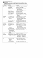
1
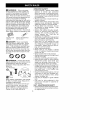
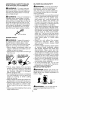
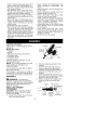
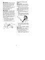
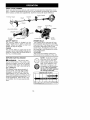
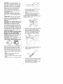
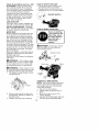
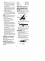
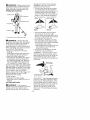
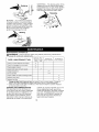
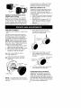
Instruction
Manual
J€:RAFTSMA#°J
34cc/2.1 cu.in. 4-Cycle
GASOLINE WEEDWAOKER
®
Model No.
358.796121
•
•
Safety
Assembly
•
•
Operation
Maintenance
•
Parts List
•
Espar_ol
For Occasional
Use Only
WARNING:
Read and follow all Safety Rules and Operating
Instructions
before first use of this product.
For answers
Call 7 am-7
to your questions about this product:
pm, Mon.-Sat.,
or 10 am-7 pm, Sun.
1-800-235-5878
Sears, Roebuck
530165093
4/20/04
and Co., Hoffman
_Hoo,s
listed are Central Time)
Estates,
IL 60179 U.S.A.
Warranty
Statement
2
Identification of Symbols
Safety Rules
Assembly
Operation
Maintenance
Service & Adjustments
2
3
8
9
15
17
Storage
18
Troubleshooting
Table
Emissions Statement
19
20
Parts List
Spanish
Parts and Ordering
FULL TWO YEAR WARRANTY ON CRAFTSMAN
WEEDWACKER ® LINE TRIMMER.
23
26
Back Cover
® GAS POWERED
For two years from the date of purchase, when this Craftsman Gas Powered
Weedwacker
Line Trimmer is maintained, lubricated, and tuned up according to
the operating and maintenance instructions in this manual, Sears will repair, free
of charge, any defect in materials or workmanship.
This warranty excludes nylon line, spark plug, and air filter, which are expendable
parts and become worn during normal use.
If this Weedwacker line trimmer is used for commercial purposes, this warranty applies for only 90 days from the date of purchase.
If this Weedwacker line trimmer is used for rental purposes, this warranty applies for
only 30 days from the date of purchase.
This warranty applies only while this product is in use in the United States.
WARRANTY SERVICE IS AVAILABLE BY RETURNING THE WEEDWACKER LINE TRIMMER
TO THE NEAREST SEARS STORE OR SERVICE CENTER IN THE UNITED STATES.
This warranty gives you specific legal rights, and you may also have other rights
which vary from state to state.
Sears, Roebuck and Co., D/817WA, Hoffman Estates, IL 60179
WARNING!
This trimmer
can be dangerous! Careless or
improper use can cause
serious or even fatal injury.
Always wear appropriate
ear protection,
Read and understand
the
instruction
manual before
using the trimmer.
eye protection
and head protection.
OPERATOR
,_LWARNING:
When using gardening appliances, basic safety precautions must always be followed to
reduce the risk of fire and serious
injury. Read and follow all instructions.
This power unit can be dangerous! Operator is responsible for following
instructions and warnings on unit and in
manual. Read entire instruction manual
before using unit! Be thoroughly familiar
with the controls and the proper use of
the unit. Restrict the use of this unit to
persons who have read, understand,
and will follow the instructions and
warnings on the unit and in the manual.
Never allow children to operate this unit.
INSTRUCTION
MANUAL
SAFETY
INFORMATION
ON THE UNIT
A
DANGER:
Never use blades
with line trimmer attachment.
Never
use flailing devices with any attachment. This unit (when used with supplied line trimmer attachment) is designed for line trimmer use only. Use
of any other accessories with line trimmer attachment will increase the risk
of injury.
Q
WARNING:
Trimmer line throws
objects violently. You and others can be
blinded/injured. Wear eye and leg
protection. Keep body parts clear of rotating line.
Eye Protection
/
SAFETY
• Dress properly.
Always wear safety
glasses
or similar
eye protection
when operating, or performing maintenance, on your unit (safety glasses
are available).
Eye protection should
be marked Z87.
• Always wear face or dust mask if operation is dusty.
• Always wear heavy, long pants, long
sleeves, boots, and gloves. Wearing
safety leg guards is recommended.
• Always wear foot protection. Do not
go barefoot or wear sandals.
Stay
clear of spinning line.
• Secure hair above shoulder length.
Secure or remove loose clothing or
clothing with loosely hanging ties,
straps, tassels, etc. They can be
caught in moving parts.
• Being fully covered also helps protect
you from debris and pieces of toxic
plants thrown by spinning line.
• Stay Alert. Do not operate this unit
when you are tired, ill, upset or under
the influence of alcohol, drugs, or
medication.
Watch what you are doing; use common sense.
• Wear hearing protection.
• Never start or run inside a closed
room or building. Breathing exhaust
fumes can kill.
• Keep handles free of oil and fuel.
• Always keep engine on the right hand
side of your body.
• Hold the unit firmly with both hands.
• Keep trimmer head (or other optional
attachment)
below waist level and
away from all parts of your body. Do
not raise engine above your waist.
• Keep all parts of you r body away from
muffler and spinning line (or other optional attachment).
Keep engine below waist level.
A hot muffler can
cause serious burns.
• Keep firm footing and balance. Do not
overreach or use from unstable surfaces such as ladders, trees, steep
slopes, rooftops, etc.
• Use only in daylight or good artificial
light.
• Use only for jobs explained
in this
manual (or manuals for optional attachments).
Hazard Zone
lm* Boots
Keep children, bystanders, and animals
50 feet (15 meters) away. Stop unit immediately if approached.
If situations occur which are not covered in this manual, use care and
good judgment.
If you need assistance, contact your Sears Service
Center or call 1-800-235-5878.
UNIT / MAINTENANCE
SAFETY
• Disconnect the spark plug before performing maintenance except carburetor adjustments.
3
• Lookforandreplace
damaged
or SAFETY NOTICE: Exposure to vibraloose
parts
before
each
use.Look
for tions through prolonged use of gasoline
andrepair
fuelleaks
before
use.Keep powered hand tools could cause blood
vessel or nerve damage in the fingers,
ingood
working
condition.
• Replace
trimmer
headpartsthatare hands, and joints of people prone to circhipped,
cracked,
broken,
ordamagedculation disorders or abnormal swellinanyother
waybefore
using
theunit. ings. Prolonged use in cold weather
• Maintain
unitaccording
to recom- has been linked to blood vessel dammended
procedures.
Keepcutting age in otherwise healthy people. If
lineatproper
length.
symptoms occur such as numbness,
• UseonlyCraftsman@
brandline. pain, loss of strength, change in skin
color or texture, or loss of feeling in the
Never
usewire,rope,
string,
etc.
• Install
required
shield
properly
before fingers,
hands, or joints, discontinue the
using
theunit.Useonlyspecified
trim- use of this tool and seek medical attenmerhead;
makesureit is properly tion. An anti-vibration system does not
guarantee the avoidance of these probinstalled
andsecurely
fastened.
• Make
sureunitisassembled
correctly lems. Users who operate power tools
asshown
inthismanual.
on a continual and regular basis must
closely their physical condition
• Makecarburetor
adjustments
with monitor
the condition of this tool.
lowerendsupported
toprevent
line and
SPECIAL NOTICE: This unit is
fromcontacting
anyobject.
• Keep
others
away
when
making
car- equipped with a temperature limiting
muffler and spark arresting screen
buretor
adjustments.
meets the requirements of Cali• Useonlyrecommended
Craftsmanwhich
Codes 4442 and 4443. All U.S.
accessories
andreplacement
parts. fornia
• Have
allmaintenance
andservice
not forest land and the states of California,
explained
inthismanual
performedIdaho, Maine, Minnesota, New Jersey,
Oregon, and Washington require by
byaSears
Service
Center.
law that many internal combustion enFUEL SAFETY
• Pour fuel outdoors.
• Keep away from sparks or flames.
• Use a container approved for fuel.
• Do not smoke or allow smoking near
fuel or the unit.
• Avoid spilling fuel or oil. Wipe up all
fuel spills.
• Move at least 10 feet (3 meters) away
from fueling site before starting engine.
• Stop engine and allow to cool before
removing fuel cap.
• Always store gasoline in a container
approved for flammable liquids.
TRANSPORTING
AND STORAGE
• Allow engine to cool before storing or
transporting in vehicle.
• Empty the fuel tank before storing or
transporting the unit. Use up fuel left in
the carburetor by starting the engine
and letting it run until it stops.
• Store or transport unit with spark plug
facing up.
• Do not store or transport unit with spark
plug facing down (see STORAGE section for additional information).
• Store unit and fuel in area where fuel
vapors cannot reach sparks or open
flames from water heaters, electric motors or switches, furnaces, etc.
• Store unit so line limiter blade cannot
accidentally cause injury.
• Store unit out of reach of children.
gines be equipped with a spark arresting screen. If you operate in a locale
where such regulations exist, you are
legally responsible for maintaining the
operating condition of these parts.
Failure to do so is a violation of the
law. For normal homeowner use, the
muffler and spark arresting screen will
not require any service. After 50 hours
of use, we recommend that your muffler be serviced or replaced by a
Sears Service Center.
_,WARNING:
The engine exhaust
from this product contains chemicals
known to the State of California to
cause cancer, birth defects, or other
reproductive harm.
LINE TRIMMER SAFETY
_,WARNING:
Inspect the area to
be trimmed before each use. Remove
objects (rocks, broken glass, nails,
wire, etc.) which can be thrown by or
become entangled in line. Hard objects can damage the trimmer head
and be thrown causing serious injury.
• Use only for trimming, scalping, mowing and sweeping. Do not use for edging, pruning or hedge trimming.
• Cut only from your left to your right.
Cutting on right side of the shield will
throw debris away from the operator=
ADDITIONAL
SAFETY
FOR OPTIONAL
BLOWER/VACUUM
RULES
ATTACHMENTS
_,WARNING:
Inspect area before
starting unit. Remove all debris and
hard objects such as rocks, glass,
wire, etc. that can ricochet, be thrown,
or otherwise cause injury or damage
during operation.
• Do not set unit on any surface except
a clean, hard area while engine is running. Debris such as gravel, sand,
dust, grass, etc., could be picked up
by the air intake and thrown out
through discharge opening, damaging unit, property, or causing serious
injury to bystanders or operator.
• Never place objects inside the blower
tubes, vacuum tubes or blower outlet.
Always direct the blowing debris away
from people, animals, glass, and solid
objects such as trees, automobiles,
walls, etc. The force of air can cause
rocks, dirt, or sticks to be thrown orto
ricochet which can hurt people or animals, break glass, or cause other
damage.
• Never run unit without the proper
equipment
attached.
When
using
your unit as a blower, always install
blower tubes.
• Check air intake opening, blower tubes
or vacuum tubes frequently, always
with engine stopped and spark plug
disconnected.
Keep vents and discharge tubes free of debris which can
accumulate and restrict proper air flow.
• Never place any object in air intake
opening as this could restrict proper
air flow and cause damage to the unit.
• Never use for spreading chemicals,
fertilizers, or other substances which
may contain toxic materials.
• To avoid spreading fire, do not use
near leaf or brush fires, fireplaces,
barbecue pits, ashtrays, etc.
BRUSHCUTTER
SAFETY
'_WARNING:
For each optional
attachment used, read entire operators manual before use and follow all
warnings and instructions in manual
and on attachment.
,_WARNING:
Ensure handlebar is
installed when using edger or brushcutter attachments.
Attach handlebar
above arrow on safety label on the upper shaft (engine end of unit). If your
edger or brushcutter attachment does
not include a handlebar, a handlebar
accessory kit (#530071451 ) is available from your Sears Service Center.
_ebar
EDGER SAFETY
WARNING:
Inspect the area to
be edged before each use. Remove
objects (rocks, broken glass, nails,
wire, etc.) which can be thrown by the
blade or can wrap around the shaft.
• Blade rotates momentarily
after the
trigger is released. The blade can seriously cut you or others.
• Allow blade to stop before removing it
from the cut.
Blade rotates
after the
SAFETY
Allow blade to stop
before removing#
from the cut.
• Throw away blades that are bent,
warped, cracked, broken or damaged
in any other way. Replace parts that
are cracked, chipped, or damaged
before using the unit.
• Do not attempt to remove cut material
nor hold material to be cut when the
engine is running or when cutting
blade is moving.
• Always keep the wheel and depth adjusting skid in contact with the ground.
• Always push the unit slowly over the
ground. Stay alert for uneven sidewalks, holes in the terrain, large roots,
etc.
• Always use the handlebarwhen
using
edger attachment.
'_DANGER:
Blade
can thrust
vio-
lently away from material it does not cut.
Blade thrust can cause amputation of
arms or legs.
'40&WARNING:
Do not use trimmer
head as a fastening device for the
blade.
5
_WARNING:Theblade
continuestospinafterthethrottle
isreleased
orengine
isturned
off.The
411WARNING:
Inspect the area to
coasting
blade
canthrow
objects
or
be cultivated before starting the unit.
seriously
cutyouifaccidentally
Remove all debris and hard and sharp
touched.
Stoptheblade
bycontactingobjects such as rocks, vines, branchthelefthand
sideofthecoasting
es, rope, string, etc.
blade
withmaterial
already
cut.
• Avoid heavy contact with solid objects
that might stop the tines. If heavy conStop
coasting
tact occurs, stop the engine and inblade
bycontact
_,_.,,,,_
spect the unit for damage.
• Never operate the cultivator without
with
cutmaterial
_
"_
the tine cover in place and properly
IliWARNING:Inspect
thearea
to
becutbefore
eachuse.Remove
objects(rocks,
broken
glass,
nails,
wire,
etc.)which
canbethrown
orbecome
entangled
intheblade
ortrimmer
line.
• Throw
away
andreplace
blades
that
arebent,
warped,
cracked,
broken
or
damaged
inanyother
way.
• Install
required
shield
properly
before
using
t
he
unit.
Use
the
metal
shield
for
allmetal
blade
use.
_,WARNING:Onlyusebrushcutterattachments
thatprovide
ametal
shield
withproboscis
nose.
% osois
• Use only specified blade and make
sure it is properly installed and securely fastened.
• Out from your right to your left.
• Always use the handlebar and a properly adjusted shoulder strap with blade
(see ASSEMBLY instructions in brushcutter attachment instruction manual).
CULTIVATOR SAFETY
secured.
• Keep the tines and guard clear of debris.
• After striking a foreign object, stop the
engine, disconnect
the spark plug
and inspect the cultivator for damage.
Repair before restarting.
• Disconnect attachment from the drive
engine before cleaning the tines with
a hose and water to remove any
build-up. Oil the tines to prevent rust.
• Always wear gloves when servicing
or cleaning the tines. The tines become very sharp from use.
• Do not run unit at high speed unless
cultivating.
HEDGE TRIMMER SAFETY
,_,DANGER:
RISK OF CUT; KEEP
HANDS AWAY FROM BLADE - Blade
moves momentarily after the trigger is
released. Do not attempt to clear away
cut material when the blade is in motion.
Make sure the switch is in the OFF position, the spark plug wire is disconnected, and the blade has stopped
moving before removing jammed material from the cutting blade. Do not grab
or hold the unit by the cutting blade.
Blades move
Allow blades to stop
momentarily
before removing
after the
them from the cut.
triggerls
_,WARNING:
Rotating tines can
cause serious injury. Keep away from
rotating tines. Stop the engine and
disconnect the spark plug before unclogging tines or making repairs.
,_&WARNING:
Inspect the area before starting the unit. Remove all debris and hard objects such as rocks,
glass, wire, etc. that can ricochet, be
6
thrown,
orotherwise
cause
injury
or
dIIWARNING:
To prevent serious
damage
during
operation.
• Donotuseacutting
blade
thatisbent, injury, do not use more than one boom
warped,
cracked,
broken
ordamaged extension with a pole pruner attachinanyother
way.Have
wornordam- ment.
agedpartsreplaced
byyourSears _bWARNING:
Keep the pruner
Service
Center.
from power lines or electrical
• Always
keep
unitinfront
ofyourbody. away
Keep
allparts
ofyourbody
away
from wires.
• Only
use
for pruning
limbs
or
thecutting
blade.
up to 4 inches in diameter.
• Keep
thecutting
blade
andairvents • branches
Do not operate the unit faster than the
clear
ofdebris.
speed needed to prune. Do not run the
POLE PRUNER
SAFETY
,_.WARNING:
The reciprocating
blade/rotating
chain can cause severe
injury. Inspect the unit before use. Do
not operate unit with a bent, cracked
or dull blade or dull chain. Keep away
from the blade/chain.
,_WARNING:
The reciprocating
blade/rotating chain is sharp. Do not
touch. To prevent serious injury, always
stop engine and ensure blade/chain
has stopped moving, disconnect spark
plug, and wear gloves when changing
or handling the blade or chain.
WARNING:
A coasting blade/rotating chain can cause injury while it
continues to move after the engine is
stopped. Maintain proper control of the
unit until the blade/chain has completely
stopped moving. Keep hands, face and
feet at a distance from all moving parts.
Do not attempt to touch or stop the
blade or chain when it is moving.
_,WARNING:
Falling objects can
cause severe head injury. Wear head
protection when operating this unit
with a pole pruner attachment.
unit at high speed when not pruning.
• Always stop the unit when work is
delayed or when walking from one
cutting location to another.
• Ifyou strike or become entangled with a
foreign object, stop the engine immediately and check for damage. Have any
damage repaired by a Sears Service
Center before attempting further operations. Discard blades that are bent,
warped, cracked or broken.
• Stop the unit immediately if you feel
excessive
vibration.
Vibration
is a
sign of trouble. Inspect thoroughly for
loose nuts, bolts or damage before
continuing. Contact Sears Service for
repair or replacement
of affected
parts as necessary.
SNOW THROWER SAFETY
_,WARNING:
Keep hands and
feet away from the rotor when starting
or running the engine. Never attempt
to clear the rotor with the engine/motor
running. Stop engine and disconnect
spark plug before unclogging snow or
debris from discharge chute or when
adjusting vanes.
&'If=WARNING:
Never lean over discharge chute. Rocks or debris could
be thrown into the eyes and face and
cause serious injury or blindness.
_;;_,WARNING:
Inspect the area
where the unit is to be used. Remove
objects that could be thrown or damage the unit. Some objects may be
hidden by fallen snow - be alert for
the possibility.
• Direct
material
discharge
away
from • Never
operate
thesnowthrower
near
glass
enclosures,
automobiles,
etc.
glassenclosures,
automobiles
and
• Donotrunengine
athighspeed
while trucks.
notremoving
snow.
• Never
attempt
tousethesnowthrow• Beattentive
whenusingthesnow- erona roof.
thrower,
andstayalertforholes
inthe • Never
operate
thesnowthrower
near
terrain
andother
hidden
hazards.
window
wells,
dropoffs,
etc.
• Make
suretherotorwillspin
freely
be- • Neverdischarge
snowontopublic
foreattaching
thesnowthrower
tothe
roads
ornearmoving
traffic.
powerhead.
• Clearsnow
fromslopes
bygoingup
anddown;
never
across.
Usecaution
• Iftherotorwillnotrotate
freely
dueto
frozen
ice,thawtheunitbefore
thor- whenchanging
directions.
Never
oughly
before
attempting
tooperate clearsnow
fromsteep
slopes.
• Letsnowthrower
runforafewminutes
under
power.
• Keep
therotorclear
ofdebris.
afterclearing
snowsomoving
parts
• Donotthrow
snow
nearother
people. donotfreeze.
Thesnowthrower
could
propel
small • Lookbehindandusecarewhen
objects
athighspeed
causing
injury.
backing
up.Exercise
caution
toavoid
• After
striking
aforeign
object,
stopthe
slipping
orfalling,
especially
when
opengine,
disconnect
spark
plugandinerating
inreverse.
spectthesnowthrower
fordamage • Know
howtostopquickly.
andrepair
ifnecessary
before
restartingunit.
CARTON
CONTENTS
Check
carton
contents
against
thefollowing
list.
Model 358.796121
• Trimmer
• Shield
• Wing Nut (screwed
• Shoulder strap
• Container of line
• Container of oil
Coupler
Shipping
protector
onto shield)
Examine parts for damage. Do not
use damaged parts.
NOTE: If you need assistance or find
parts missing or damaged, call
1-800-235-5878.
It is normal for the fuel filter to rattle in
the empty fuel tank.
Finding fuel or oil residue on muffler is
normal due to carburetor adjustments
and testing done by the manufacturer.
ASSEMBLY
_f_,WARNING:
If received assembled, read and use this ASSEMBLY
section to verify that your unit is properly
assembled and that all fasteners are
tightened securely.
INSTALLING TRIMMER
ATTACHMENT
CAUTION:
When installing trimmer
attachment, place the unit on a flat
surface for stability.
1. Loosen the coupler by turning the
knob counterclockwise.
\
Knob
TIGHTEN
2.
3.
4.
5.
6.
Remove shipping protector from
coupler.
Remove the shaft cap from the
trimmer attachment (if present).
Position locking/release
button of
attachment into guide recess of
coupler.
Push the attachment into the coupler until the locking/release
button
snaps into the primary hole.
Before using the unit, tighten the
knob securely by turning clockwise.
Coupler
Upper
Shaft
Primary Hole
Guide Recess
Locking/
Release
Button
Lower
Attachment
z_
_WARNING:
Make sure the locking/release button is locked in the primary hole and the knob is securely
tightened before operating the unit.
All attachments are designed to be
used in the primary hole.
For optional attachments, see the ASSEMBLY section of the applicable attachment instruction manual.
ATTACHING
SHIELD
_WARNING:
The shield must be
properly installed. The shield provides
partial protection to the operator and
others from the risk of thrown objects,
and is equipped with a line limiter blade
which cuts excess line to the proper
length. The line limiter blade (on underside of shield) is sharp and can cut you.
For proper orientation of shield, see
KNOW YOUR TRIMMER illustration in OPERATION section.
1. Remove wing nut from shield.
2. Insert bracket into slot as shown.
3. Pivot shield until bolt passes
through hole in bracket.
4. Securely tighten wing nut onto bolt.
ATTACHING
STRAP
'_WARNING:
Proper shoulder
strap adjustments must be made with
the engine completely stopped before
using unit.
1. Insert your right arm and head
through the shoulder strap and allow it to rest on your left shoulder.
NOTE: A one-half twist is built in the
shoulder strap to allow the strap to rest
flat on the shoulder.
2. Adjust the strap, allowing the hook
to be about 6 inches below the
waist.
3. Fasten the strap hook to the shoulder strap attachment hole located
on the trigger handle and lift the tool
to the operating position.
}houlder strap
attachment
hole
4.
SIotB__,/_Wing
_<
Shield
Nut
THE SHOULDER
Try on shoulder strap and adjust
for fit and balance before starting
the engine or beginning a cutting
operation.
ADJUSTING
THE ASSIST
HANDLE
_bWARNING:
When adjusting
assist handle, be sure it remains
above the safety label and below
mark or arrow on the shaft.
1. Loosen wing nut on handle.
2. Rotate the handle on the shaft
upright position; retighten wing
the
the
to an
nut.
KNOW
YOUR
TRIMMER
READ THIS iNSTRUCTiON MANUAL AND SAFETY RULES BEFORE OPERATING YOUR
UNIT. Compare the illustrations with your unit to familiarize yourself with the location
of the various controls and adjustments. Save this manual for future reference.
Assist Handle
Trimmer
Head
Shaft
Coupler
Choke
Lever
Spark
_/
Plug
Muffler
Limiter Blade
ON/OFF Switch
Line
Fuel fill
__,_//
Throttle S
Starter Handle
Trigger
ON/OFF SWITCH
Tile ON/OFF switch is located on the
trigger handle and is used to stop the
engine. Move the switch to the OFF
position to stop the engine.
CHOKE
Tile CHOKE helps to supply fuel to the
engine to aid in cold starting. Activate the
choke by moving the red choke lever to
the FULL CHOKE position.
BEFORE STARTING
_,WARNING:
/
Dipstick
Primer Bulb
PRIMER BULB
The PRIMER BULB removes air from
the carburetor and fuel lines and fills
them with fuel. This allows you to start
the engine with fewer pulls on the
starter rope. Activate the primer bulb
by pressing it and allowing it to return
to its original form.
COUPLER
The COUPLER enables optional attachments to be installed on the unit.
ENGINE
,_.,_--.
NOTE:
;,"_ '"
,<._o,_j
ing ILSAC
cation
mark
GF-2,
and API
API certifiservice symbol (shown at left)
with "SJ/CF ENERGY CON-
'\_
Be sure to read
the fuel information in the safety rules
before you begin. If you do not understand the safety rules, do not attempt
to fuel your unit. Call 1-800-235-5878.
OIL CAPACITY
Synthetic
oil meet-
acceptable oil at all temperSERVING"
higher,
is an
atures.
Useor of
synthetic
oil does not alter required
oil change intervals.
O
The engine holds approximately 3
ounces of oil. Use only high quality
detergent oil rated with API service
classification SJ-SL Select the oil's
SAE viscosity grade according to your
expected operating temperature.
For
most applications, SAE-30 oil is recommended. Do not use special additives.
SAE Viscosity Grades
i
t
2+0
S+AR I iftO
lO
._o
t
70
I E%I_ERATURE
I
7o
RA_IGE AN I CIFA
_
ED P:mro_E
J
I,E_
OIL C_AN6F
;_
CAUTION:
Air cooled engines run
hotter than automotive engines. The
use of non-synthetic
multi-viscosity
oils (5W30, 10W30, etc.) in temperatures above 40"F (4"C) will result in
higher than normal oil consumption.
When using a multi-viscosity
oil,
check oil level more frequently to
avoid possible engine damage from
running low on oil.
*CAUTION: Synthetic oil must be
used when operating engine under
40"F (4"C) or engine damage will occur.
**CAUTION:
SAE 30 oil, if used below 50°F (10°C), will result in hard
starting and possible engine damage
due to inadequate lubrication.
ADD OIL
Your trimmer is shipped without oil in
the engine. The engine holds approximately 3 fluid ounces (90 ml) of oil
when at the FULL mark on the oil dipstick. Included with this trimmer is a 3.4
ounce (90 ml) container of SAE 30 SJSL oil for properly filling the engine with
oil for first time use only. Pour the entire
contents of this 3.4 ounce container of
oil into the oil fill spout.
NOTE: The dipstick will show slightly
above FULL. This is acceptable for
first time use only as the engine
breaks in. After the first time oil fill, simply refill the engine with oil to the FULL
mark on the dipstick as needed.
CAUTION:
DO NOT overfill engine with
oil or it will smoke on start-up.
CAUTION:
KEEP ENGINE LEVEL
----
r
------
1 ounce ---.,__
0.5 ounce __
1.
Be sure engine is level and area
around oil fill is clean.
2. Remove oil dipstick from oil fill
spout.
3. Using a measure cup, pour oil
slowly down the oil fill spout into
the engine. Do not overfill.
NOTE: Engine holds approximately
3
ounces (90 ml) of oil.
Oil fill
4.
5.
Wait one minute to allow oil to settle.
Insert and hand tighten dipstick.
Remove dipstick and wipe clean
with cloth. Clear dipstick hole of oil.
Insert and hand tighten dipstick,
then remove it to check oil level.
\Dipstick..
f_-
....
%
Engine must be level, with oil fill facing
up, to check oil. If engine is not level,
dipstick reading will not be accurate.
This will lead to possible over or under
filling causing damage to the engine.
•
•
•
•
6.
Check oil level before starting the engine.
Check oil level before every use.
Keep oil level at FULL.
DO NOT overfill. Use a measure cup for
filling.
Add only 1 ounce--0.5 ounce at a time.
Verify FULL level of oil by presence
of oil in hole on dipstick, or by
measure line.
FULL
7.
8.
11
_._._
If needed, add 0.5 ounce of oil at a
time and recheck the dipstick until
oil reaches
the FULL level.
Always be sure to retighten oil dipstick before starting engine.
Check oil level before each use. Add
oil if needed. Fill to FULL line on dipstick. Change oil after first 4 hours of
use, then every 8 hours of operation
or each season (see CHANGE ENGINE
OIL in the MAINTENANCE section).
Change oil every 4 hours when operating the engine under heavy load or
in high temperatures. You may need
to change the oil more often under
dusty, dirty conditions.
HOW TO STOP YOUR UNIT
• To stop the engine, move the ON/
OFF switch to the OFF position.
• If engine does not stop, move red
choke lever to FULL CHOKE position.
ON/OFF
SWITCH
ADD GASOLINE
Use fresh, clean, regular unleaded gasoline with a minimum of 87 octane. Do
not mix oil with gasoline.
Purchase
fuel in quantities that can be used within
30 days to assure fuel freshness.
IMPORTANT
Alcohol blended fuels (called gaeohol
or using ethanol or methanol) can attract moisture which leads to separation and formation of acids during storage. Acidic gas can damage the fuel
system of an engine while in storage.
To avoid engine problems, empty the
fuel system before storage for 30 days
or longer. Drain the gas tank, start the
engine and let it run until the fuel lines
and carburetor are empty. Use fresh
fuel next season.
Never use engine or carburetor cleaner
products in the fuel tank or permanent
damage may occur.
See the STORAGE section for additional
information.
&WARNING:
Fill to bottom of gas
tank filler neck. DO NOT overfill. Wipe
off any spilled fuel. Do not store, spill
or use gasoline near an open flame.
_I_WARNING:
Allow engine to cool
for 2 minutes before removing fuel cap
for refueling. Remove fuel cap slowly.
1. Tilt engine in angle shown to properly fill fuel tank.
HOW TO START YOUR UNIT
your engine for the
FIRST time, follow
the steps listed in
f you
are starting
the
STARTING
A
NEW ENGINE
section.
O
A _______
41_WARNING:
Avoid any contact
with the muffler. A hot muffler can
cause serious burns.
Starting
Choke
Lever
Position
Muffler
Throttle
Trigger
Prime
Bulb
_'F'FFuel
fill
2.
3.
Remove fuel cap by turning counterclockwise.
Fill tank to bottom of
tank filler neck.
Replace fuel cap before starting.
STARTING A NEW ENGINE
NOTE: Add oil and fuel as instructed
in this manual prior to attempting to
start engine (see ADD OIL and ADD
GASOLINE sections).
1. Set unit on a flat surface.
2. Slowly press the primer bulb 15
times.
3. Move red choke lever to FULL
CHOKE position.
4. Squeeze the throttle trigger fully and
hold through all remaining steps.
12
5=Pullstarter
ropehandle
sharply
until
engine
runs.
6=Once
theengine
starts,
allow
itto
runamaximum
of10seconds
at
FULL
CHOKE.
Then,
slowly
move
theredchoke
lever
totheHALF
CHOKE
position.
7=Allowtheunittorunaminimum
of
20more
seconds
atHALF
CHOKE
(colder
temperatures
mayrequire
longer
warm-up
periods
before
theengine
willaccept
aloadand
accelerate
properly).
8=Move
redchoke
lever
toOFF
CHOKE
position
andallow
theunitto
runaminimum
of20more
seconds
atOFF
CHOKE.
Release
thethrottle
trigger.
STARTING
Edger ...............
Cultivator ............
Blower ..............
Brusbcutter
..........
Pruner ..............
358.792403
358.792410
358.792421
358.792443
358.792450
,_WARNING:
Always stop unit
and disconnect spark plug before removing or installing attachments.
REMOVING TRIMMER ATTACHMENT (OR OTHER OPTIONAL ATTACHMENTS)
CAUTION:
When removing or installing attachments, place the unit on a
flat surface for stability.
1. Loosen the coupler by turning the
knob counterclockwise.
Upper Shaft
ENGINE
NOTE: Check oil level before starting.
Oil level should be at the FULL mark
on the dipstick. If not, add oil (see
ADD OIL section).
1. Set unit on a flat surface.
2= Slowly press the primer bulb 8
times.
3= Move red choke lever to FULL
CHOKE position.
4= Squeeze the throttle trigger fully and
hold through all remaining steps.
5= Pull starter rope handle sharply until
engine runs.
6= Once the engine starts, allow it to
run a maximum of 10 seconds at
FULL CHOKE. Then, slowly move
the red choke lever to the HALF
CHOKE position.
7= Allow the unit to run a minimum of
20 more seconds at HALF CHOKE
(colder temperatures
may require
longer warm-up periods before
the engine will accept a load and
accelerate properly).
8= Move red choke lever to OFF
CHOKE position and allow the unit to
run a minimum of 20 more seconds
at OFF CHOKE. Release the throttle
trigger.
RESTARTING A WARM ENGINE
Follow steps listed in the STARTING
ENGINE section without squeezing
throttle trigger.
If the unit will not start, refer to the
TROUBLESHOOTING TABLE or call
1-800-235-5878.
OPERATING THE COUPLER
This model is equipped with a coupler
which enables optional attachments to
be installed. The optional attachments are:
Coupler
Lower
\
Attachment
TIGHTEN
2.
Press and hold
button.
Locking/Release
Button
Knob
the locking/release
Upper Shaft
Lower Attachment
3.
While securely holding the engine
and upper shaft, pull the attachment straight out of the coupler=
INSTALLING OPTIONAL
ATTACHMENTS
1. Remove the shaft cap from the attachment (if present).
2. Position locking/release
button of
attachment into guide recess of
coupler.
3. Push the attachment into the coupler until the locking/release
button
snaps into the primary hole.
4. Before using the unit, tighten the
knob securely by turning clockwise=
couple r Primary Hole
Guide Recess
Upper
Shaft
13
Locking/
Release
Button
Attachment
_WARNING:
Make sure the locking/release button is locked in the primary hole and the knob is securely
tightened before operating the unit.
OPERATING
POSITION
t
ALWAYS
WEAR:
. |___,_
damage the trimmer head, become
entangled in the line, or be thrown
causing a serious hazard.
• The tip of the line does the cutting.
You will achieve the best performance and minimum line wear by not
crowding the line into the cutting
area. The right and wrong ways are
shown in the following illustrations.
Tip of line does the Line crowded into
er strap
Long pa
Right
Heavy sh_l_
t
,_
Cut only from your left to your right,
all.WARNING:
Always wear eye
protection. Never lean over the trimmer
head. Rocks or debris can ricochet or
be thrown into eyes and face and
cause blindness or other serious injury.
When operating unit, stand as shown
and check for the following:
• Wear eye protection and heavy
clothing.
• Hold trigger handle with right hand
and assist handle with left hand.
• Keep unit below waist level.
• Cut only from your left to your right to
ensure debris is thrown away from
you. Without bending over, keep line
near and parallel to the ground and
not crowded into material being cut.
Do not run the engine at a higher speed
than necessary. The cutting line will cut
efficiently when the engine is run at less
than full throttle. At lower speeds, there
is less engine noise and vibration.
• The line will easily remove grass
and weeds from around walls,
fences, trees and flower beds, but it
also can cut the tender bark of trees
or shrubs and scar fences.
• For trimming or scalping, use less
than full throttle to increase line life
and decrease head wear, especially:
• During light duty cutting.
• Near objects around which the line
can wrap such as small posts,
trees or fence wire.
• For mowing or sweeping, use full
throttle for a good clean job.
TRIMMING - Hold the bottom of the
trimmer head about 3 inches (8 cm)
above the ground and at an angle. Allow only the tip of the line to make
contact. Do not force trimmer line into
work area.
Trimming
Always release the throttle trigger and
allow the engine to return to idle
speed when not cutting.
To stop engine:
• Release the throttle trigger.
• Move the ON/OFF switch to the OFF
position.
CUTTING METHODS
,_WARNING:
Use minimum
speed and do not crowd the line when
cutting around hard objects (rock,
gravel, fence posts, etc.), which can
Wrong
3 inches (8 crr
above ground
SCALPING - The scalping technique
removes unwanted vegetation down
to the ground. Hold the bottom of the
trimmer head about 3 inches (8 cm)
above the ground and at an angle. Allow the tip of the line to strike the
ground around trees, posts, monuments, etc. This technique increases
line wear.
14
SWEEPING - The fanning action of the
rotating line can be used to blow away
loose debris from an area. Keep the line
parallel to and above the area surface
and swing the tool from side to side.
Scalping
Sweeping
MOWING - Your trimmer is ideal for
mowing in places conventional lawn
mowers cannot reach. In the mowing
position, keep the line parallel to the
ground. Avoid pressing the head into
the ground as this can scalp the
ground and damage the tool.
Mowing
MAINTENANCE
SCHEDULE
,_LWARNING:
Disconnect the spark plug before performing
except for carburetor adjustments.
CARE & MAINTENANCE
Check for loose fasteners
Check for damaged
TASK
Before
After
Every
Use
Every
Use
maintenance
8 Hours or
Every Season
50 Hours or
Every Season
and parts
or worn parts
Check engine oil level
Inspect and clean unit and decals
Change engine oil
Service air filter
Inspect muffler and spark arresting screen
Replace
spark plug
Replace
fuel filter
Change oil after first 4 hours of use, then every 8 hours or every season, Change oil
every 4 hours when operating the engine under heavy load or in high temperatures,
** Clean more often under dusty conditions or when airborne debris is present. Replace
air cleaner parts ifvery dirty.
GENERAL RECOMMEN DATIONS
The warranty on this unit does not
cover items that have been subjected
to operator abuse or negligence. To
receive full value from the warranty,
the operator must maintain unit as
instructed in this manual. Various adjustments will need to be made peri-
odically to properly maintain your unit.
Some adjustments will need to be
made periodically to properly maintain
your unit. All adjustments in the SERVICE AND ADJUSTMENTS section of
this manual should be checked at
least once each season.
15
• Once each year, replace the spark
plug and air filter. A new spark plug
and clean/new air filter assure proper
air-fuel mixture and help your engine
run better and last longer.
• Follow the maintenance
schedule in
this manual.
CHECK FOR LOOSE
FASTENERS AND PARTS
• Spark Plug Boot
• Air Filter
• Housing Screws
• Assist Handle Screw
• Debris Shield
CHECK FOR DAMAGED
WORN PARTS
hold waste. Contact Sears Service for
information regarding safe disposal/recycling facilities.
Change oil while engine is OFF, but
still warm. Ensure fuel cap is tightened
securely.
1. Remove engine oil fill cap/dipstick;
lay aside on a clean surface.
2. Drain oil into a suitable container in
direction shown (see illustration).
OR
For replacement of damaged or worn
parts, contact Sears Service or call
1-800-235-5878.
• ON/OFF Switch - Ensure ON/OFF
switch functions properly by moving
the switch to the OFF position. Make
sure engine stops. Restart engine
and continue.
• Fuel System - Discontinue use of
unit if fuel lines, tank, or cap show
signs of damage or leaks.
• Debris Shield - Discontinue use of
unit if debris shield is damaged.
CHECK ENGINE OIL LEVEL
• See ADD OIL in the OPERATION section.
INSPECT AND CLEAN UNIT AND DECALS
• After each use, inspect complete
unit for loose or damaged parts.
Clean the unit and decals using a
damp cloth with a mild detergent.
• Wipe off unit with a clean dry cloth.
CHANGE ENGINE OIL
To prolong the useful life of your trimmer, change engine oil as recommended in this section.
• Change oil after first 4 hours of
use, then every 8 hours or every
season. Change oil every 4 hours
when operating the engine under
heavy load or in high temperatures.
Change the oil after every 8 hours of
operation or at least once a year if the
unit is not used for 25 hours in one
year. Check the crankcase oil level before each start. Tighten oil dipstick securely each time you check the oil level.
CHANGING OIL AND CHECKING
LEVEL
CAUTION:
Used oil is a hazardous
waste product, Dispose of used oil
properly. Do not discard with house-
3.
Wipe off any spilled oil from trimmer.
4. Fill engine with oil (see ADD OiL in
the OPERATION section).
5. Replace engine oil fill cap/dipstick.
Tighten securely.
CLEAN AIR FILTER
A dirty air filter decreases engine performance and increases fuel consumption and harmful emissions. Always clean after every 8 hours of
operation. Clean more often under
dusty conditions or when airborne debris is present. Replace air cleaner
parts if very dirty.
1. Clean the cover and the area
around it to keep dirt from falling
into the carburetor chamber when
the cover is removed.
NOTE: Move red choke lever to FULL
CHOKE position before removing components.
2. Remove parts by pressing button
to release air filter cover.
NOTE: To avoid creating a fire hazard
or producing harmful evaporative
emissions, do not clean filter in gasoline or other flammable solvent.
3. Wash the filter in soap and water.
4. Allow filter to dry.
5. Add a few drops of oil to the filter;
squeeze the filter to distribute oil.
6. Re-assemble
parts.
16
ommend that your muffler and spark
arresting screen be serviced or replaced by a Sears Service Center.
REPLACE SPARK PLUG
Button
Air Filter
INSPECT MUFFLER AND SPARK
ARRESTING
SCREEN
As the unit is used, carbon deposits
build up on the muffler and spark arresting screen. For normal homeowner use, however, the muffler and spark
arresting screen will not require any
service. After 50 hours of use, we rec-
Replace the spark plug each year to
ensure the engine starts easier and
runs better. Set spark plug gap at
0.025 inch. Ignition timing is fixed and
nonadjustable.
1. Twist, then pull off spark plug boot.
2. Remove spark plug from cylinder
and discard.
3. Replace with Champion RDJ-7Y
spark plug and tighten securely
with a 5/8 inch (15 mm) socket
wrench.
4. Reinstall the spark plug boot.
LINE REPLACEMENT
4.
Cover
• Always
line.
use Craftsman
replacement
Choose the line size best suited for
the job at hand. Red line is designed
for cutting grass and small weeds.
The black colored line is designed for
cutting larger weeds and light brush.
NOTE: Before inserting new line into
the holes in the cutting head, identify
the proper holes. Follow directions as
shown on the line glide plate.
1. Remove the old line and line glide
plate from the cutting head.
2. Clean entire surface of cutting head.
3. Reinstall line glide plate (see illustration). Align arrow with:
Positioning
Tunnel
5.
Pull the line and make sure the
line is against the hub and extended full through the positioning
tunnels.
Line against
the hub
Positioning
Tunnel \
6.
Correctly installed line will be the
same length on both ends.
(_) when using medium (red) or
large (black) line
(_
when using lines with diameter
smaller than medium (red) line
(optional)
Line glide
Insert both ends of your line
through the proper holes in the
side of the cutting head.
Arrow
Cutting head
NOTE: Line glide plate must be reinstalled in cutting head before inserting
new line.
CARBURETOR
ADJUSTMENT
Adjusting the carburetor is a complicated task. Carburetor adjustment is
critical and if done improperly can permanently damage the engine as well as
the carburetor. We recommend that you
take your unit to a Sears Service Center
for any necessary adjustments.
17
all.WARNING:
Perform
thefollowCAUTION:
Storing unit in
ingsteps
aftereach
use:
• Allow
engine
tocoolbefore
storing
• ortransporting.
Store
unitandfuelinawellventilated
areawhere
fuelvapors
cannot
reach
sparks
oropen
flames
from
water
heaters,
electric
motors
or
switches,
furnaces,
etc.
• Store
unitwithallguards
inplace.
Position
unitsothatanysharp
objectcannot
accidentally
cause
injury.
• Store
unitandfuelwelloutofthe
reach
ofchildren.
over 10 degrees
• Store
theunitinahorizontal
position
withthespark
plugfacing
up.
• DONOT
storeortransport
theunit
withthespark
plugfacing
down.
NOTE: Storing or transporting the unit
SEASONAL
STORAGE
with the spark plug down may result in
Prepare
unitforstorage
atendofsea- white smoke coming from the muffler
sonorifitwillnotbeused
for30days or difficult starting.
ormore.
removing the unit from storIfyourunitistobestored
foraperiod • When
age, only use fresh gasoline. Peroftime:
form the routine operation checks as
• Clean
theentire
unitbefore
lengthy described in this manual before any
storage.
start.
• Store
inaclean
dryarea.
FUEL SYSTEM
• Lightly
oilexternal
metal
surfaces.
• Wehighly
recommend
thatyoudrain Under ADD GASOLINE in the OPERAthefueltankpriortolengthy
storage TION section of this manual, see mes(30daysormore).
Drain
allfuelfrom sage labeled IMPORTANT regarding
thefueltankintotheproper
recep- the use of gasohol in your engine.
• Never use engine or carburetor
tacles
forstorage.
cleaner products in the fuel tank or
• Press
p
urge
b
ulb
15times
t
oremove
allfuelfromcarburetor
and
permanent damage may occur.
fuelline.Drain
thisfuelintoproper • Use fresh fuel next season.
receptacles.
Iffuelistobedisposed, ENGINE OIL
please
refertolocalrules
forproper • Drain engine oil (with engine warm)
disposal.
and replace with clean oil. See
• Remove
spark
plug.
CHANGE ENGINE OIL in the MAINTE• Place
5ccofoilintospark
plughole. NANCE section.
Donotoverfill.
CYLINDER
• Pullthestarter
rope
slowly
8 - 10
Replace spark plug with new one of
times
toproperly
coatthecylinder • recommended
type and heat range.
boreandpiston
forstorage.
Replace
OTHER
plugandtighten.
Anyresidual
oil
• Clean air filter.
mayburnoffinsubsequent
starts
which
mayresult
inwhite
smoke
• Check entire unit for loose screws,
fromthemuffler.
nuts, and bolts. Replace any dam• Store
theunitinahorizontal
position aged, broken, or worn parts.
withthespark
plugup.DONOT
store • Do not store gasoline from one seaortransport
theunitwiththespark
son to another.
plugdown.
• Replace your gasoline can if it starts
to rust.
18
TROUBLESHOOTING
TABLE
_,WARNING:
Always stop unit and disconnect spark plug before performing all of the recommended
remedies below except remedies that require
operation of the unit.
TROUBLE
CAUSE
REMEDY
Engine will not
start.
1. Move ON/OFF switch to ON position,
1. ON/OFF switch in OFF
position.
2. Air filter dirty.
3. Fuel tank empty.
4. Stale fuel.
2. Clean or replace air filter.
3. Fill fuel tank.
4. Drain tank and carburetor and refill
with fresh, clean fuel.
5. Drain tank and carburetor and refill
tank with fresh gasoline.
6. Connect wire to plug.
5. Water in fuel.
6. Spark plug wire is
disconnected.
7. Spark plug not firing.
8. Fuel not reaching
carburetor.
7. Install new spark plug.
8. Check for dirty fuel filter; replace.
Check for kinked or split fuel line;
repair or replace.
9. Press primer bulb to remove air from
fuel lines.
9. Air in fuel lines.
Engine will
not idle
properly.
1. Choke lever in FULL
CHOKE position.
2. Carburetor requires
adjustment.
3. Stale fuel.
4. Crankshaft
5. Compression
Engine will not
accelerate,
lacks power.
or dies under
a load.
1. Move choke lever to OFF CHOKE.
2. See "Carburetor Adjustment" in
Service and Adjustments
Section.
3. Drain tank and carburetor and refill
with fresh, clean fuel.
4. Contact Sears Service (see back
cover).
5. Contact Sears Service (see back
cover).
seals worn.
low.
1. Air filter dirty.
2. Spark plug fouled.
3. Choke lever in FULL
CHOKE position.
4. Stale fuel.
1. Clean or replace air filter.
2. Clean or replace plug and regap.
3. Move choke lever to OFF CHOKE.
4. Drain tank and carburetor and refill
with fresh, clean fuel.
5. See "Carburetor Adjustment" in
Service and Adjustments
Section.
6. Contact Sears Service (see back
cover).
7. Check oil level. Drain to proper level.
8. Run unit for longer period.
5. Carburetor requires
adjustment.
6. Carbon build-up on
muffler outlet screen.
7. Too much oil in engine.
8. Engine not warmed up in
cooler temperature.
9. Cutting line assembled
incorrectly or line length
incorrect.
Engine
smokes
excessively.
Engine
hot.
runs
9. Check line assembly
1. Air filter dirty.
2. Too much oil in engine.
3. Oil migration from incorrect
storage or transportation.
1. Spark plug incorrect.
2. Carburetor requires
adjustment.
3. Debris clogging starter
housing.
4. Carbon build-up on
muffler outlet screen.
and length.
1. Clean or replace air filter.
2. Check eil level. Drain to proper level.
3. Allow unit to sit 24 hours in correct
storage position, or remove spark
plug. pull rope 2 - 3 times, then replace spark plug. Pull rope until
engine starts.
1. Replace with correct spark plug.
2. See "Carburetor Adjustment"
in
Service and Adjustments Section.
3. Clean starter housing area.
4. Contact
cover).
19
Sears Service
(see back
YOUR WARRANTY RIGHTS AND OBLIGATIONS: EMISSION CONTROL
WARRANTY COVERAGE IS APPLICABLE TO CERTIFIED ENGINES
PURCHASED IN CALIFORNIA IN 1995
AND THEREAFTER WHICH ARE
USED IN CALIFORNIA, AND TO CERTIFIED MODEL YEAR 1997 AND LATER ENGINES WHICH ARE PURCHASED AND USED ELSEWHERE IN
THE UNITED STATES (AND AFTER
JANUARY 1,2001, IN CANADA).
CALIFORNIA AND UNITED STATES
EMISSION CONTROL DEFECTS
WARRANTY STATEMENT: The U.S.
Environmental Protection Agency/California Air Resources Board and Sears,
Roebuck and Co., U.S.A., are pleased
to explain the emissions control system
warranty on your year 2000 and later
small off-road engine (SORE). In California, all new small off-road engines
must be designed, built, and equipped
to meet the State's stringent anti-smog
standards. Elsewhere in the United
States, new non-road, spark-ignition
engines certified for model year 1997
and later, must meet similar standards
set forth by the U.S. EPA. Sears must
warrant the emission control system for
the periods of time listed below provided
there has been no abuse, neglect, or
improper maintenance of your small offroad engine engine. Your emission control system includes parts such as the
carburetor, air cleaner, ignition system,
muffler and catalytic converter. Also included may be connectors and other
emissions-related
assemblies. Where a
warrantable condition exists, Sears will
repair your small off-road engine engine at no cost to you. Expenses covered under warranty include diagnosis,
parts and labor. MANUFACTURER'S
EMISSION CONTROL DEFECTS
WARRANTY COVERAGE: Small offroad engines are warranted relative to
emission control parts defects for a period of two years, subject to these provisions. If any covered part on your engine is defective, the part will be
repaired or replaced by Sears. OWNER'S WARRANTY RESPONSIBILITIES: As the small off-road engine engine owner, you are responsible for the
performance of the required maintenance listed in your operating and
maintenance instructions. Sears recom-
mends that you retain all receipts covering maintenance on your small off-road
engine, but Sears cannot deny warranty
solely for the lack of receipts or for your
failure to ensure the performance of all
scheduled maintenance. As the small
off-road engine engine owner, however,
you should be aware that Sears may
deny you warranty coverage if your
small off-road engine or a part has
failed due to abuse, neglect, improper
maintenance or unapproved modifications. You are responsible for presenting
your small off-road engine to an approved Sears Service Center as soon
as a problem exists. The undisputed
warranty repairs should be completed in
a reasonable amount of time, not to exceed 30 days. If you have any questions regarding your warranty rights and
responsibilities, you should contact your
nearest approved service center or call
Sears Service at 1-800-469-4663.
The
emission warranty is a defects warranty.
Defects are judged on normal engine
performance. The warranty is not related to an in-use emission test.
SEARS EMISSION CONTROL
DEFECTS WARRANTY PROVISIONS
The following are specific provisions
relative to your Emission Control Defects Warranty Coverage. It is in addition to the Sears engine warranty for
non-regulated
engines found in the
operating and maintenance instructions.
1. Warranted Parts
Coverage under this warranty extends only to the parts listed below
(the emission control systems
parts) to the extent these parts
were present on the engine purchased.
a. Fuel Metering System
• Cold start enrichment system
• Carburetor and internal parts
• Fuel pump
b. Air Induction System
• Air cleaner
• Intake manifold
c. Ignition System
• Spark plug(s)
• Magneto ignition system
d. Catalyst System
• Catalytic converter
• Exhaust manifold
• Air injection system or pulse
valve
20
e.
2.
3.
4.
Miscellaneous
Items Used in
Above Systems
• Vacuum, temperature, position, time sensitive valves
and switches
• Connectors and assemblies
Length of Coverage
Sears warrants to the initial owner
and each subsequent purchaser
that the Warranted Parts shall be
free from defects in materials and
workmanship
which caused the
failure of the Warranted Parts for a
period of two years from the date
the engine is delivered to a retail
purchaser.
No Charge
Repair or replacement of any Warranted Part will be performed at no
charge to the owner, including
diagnostic labor which leads to the
determination that a Warranted
Part is defective, if the diagnostic
work is performed at an approved
Sears Service Center.
Claims and Coverage Exclusions
Warranty claims shall be filed in
accordance with the provisions of
the Sears warranty policy. Warranty coverage shall be excluded for
failures of warranted parts which
are not original Sears parts or because of abuse, neglect or improper maintenance as set forth in the
Sears Engine Warranty Policy.
Sears is not liable to cover failures
of Warranted Parts caused by the
use of add-on, non-original,
or
modified parts.
5.
6.
Maintenance
Any Warranted Part which is not
scheduled for replacement as required maintenance or which is
scheduled only for regular inspection to the effect of "repair or replace as necessary" shall be warranted as to defects for the
warranty period. Any Warranted
Part which is scheduled for replacement as required maintenance shall be warranted as to defects only for the period of time up
to the first scheduled replacement
for that part. Any replacement part
that is equivalent in performance
and durability may be used in the
performance of any maintenance
or repairs. The owner is responsible for the performance of all required maintenance,
as defined in
the operating and maintenance
instructions.
Consequential
Coverage
Coverage hereunder shall extend to
the failure of any engine components caused by the failure of any
Warranted Part still under warranty.
In the U.S.A. and Canada, a 24-hour
hot line, 1-800-469-4663,
has a
menu of pre-recorded
messages offering you engine maintenance information.
21
LOOK FOR RELEVANT EMISSIONS DURABILITY
PERIOD AND AIR INDEX
INFORMATION
ON YOUR ENGINE EMISSIONS LABEL
The Air Index is a calculated number
Engines that are certified to meet the
California Air Resources Board
describing the relative level of emis(CARB) Tier 2 Emissions Standards
sions for specific engine family. The
lower the Air Index, the cleaner the
must display information regarding the
Emissions Durability Period and Air
engine. This information is displayed
index. Sears makes this information
in graphical form on the emissions laavailable to the consumer on our
bel or hang tag.
emission labels and hang tags.
AFTER JULY 1, 2000, LOOK FOR
EMISSIONS COMPLIANCE
PERIOD
The Emissions Durability Period describes the number of hours of actual
ON ENGINE EMISSIONS COMrunning time for which the engine is
PLIANCE LABEL
certified to be emissions compliant,
After July 1, 2000, certain Craftsman
assuming proper maintenance in acengines will be certified to meet the
cordance with the operating and mainUnited States Environmental Protectenance instructions.
The following
tion Agency (U.S. EPA) Phase 2 Class
categories are used:
IV emissions standards.
For Phase 2
Moderate:
Engine is certified to be
Class IV certified engines, the Emisemission compliant for 50 hours of acsions Compliance
Period referred to
tual engine running time.
on the emissions compliance label inIntermediate:
Engine is certified to
dicates the number of operating hours
be emission compliant for 125 hours
for which the engine has been shown
of actual engine running time.
to meet federal emission requireExtended: Engine is certified to be
ments. For engines equal to or greatemission compliant for 300 hours of
er than 20 cc, and less than 50 cc disactual engine running time.
placement, Category C = 50 hours, B
= 125 hours, and A = 300 hours.
For example, a typical consumer
string trimmer is used 5 to 10 hours
The displacement
of Model Series
per year. Therefore, the Emissions
21000 engines is 34 cc, 21100 enDurability Period of an engine with
gines is 40 cc.
an moderate rating would equate to 5
to 6 years.
This is a generic representation of the emissions
compliance label typically
found on a certified engine:
This engine is certified to be emissions
[]
Moderate
[]
Intermediate
[]
Extended
compliant
(50 hours)
(125 hours)
(300 hours)
22
for the following
use: