Download Charnwood LA30iB Operating instructions
Transcript
CHARNWOOD LA30iB Roomheater With Boiler Operating and Installation Instructions Bishops Way, Newport, Isle Of Wight, PO3O 5WS, U.K. Tel: (01983) 527552 Fax: (01983) 821267 E-Mail: [email protected] Internet: www.charnwood.com CHARNWOOD LA30iB Operating and Installation Instructions Contents Operating Instructions General Points ...................................................3 Fuels ...................................................................3 Door Operation..................................................3 Lighting..............................................................3 Controlling The Fire .........................................3 Running The Fire With The Doors Open .......4 Heating System..................................................4 Ash Clearance....................................................4 Riddling..............................................................4 Refuelling...........................................................4 Overnight Burning.............................................4 Throat Plate & Flueway Cleaning ...................5 Maintenance.......................................................5 Chimney Sweeping............................................5 Trouble Shooting...............................................6 Installation Instructions Health & Safety Precautions ............................7 Performance.......................................................7 Chimney.............................................................7 Hearth.................................................................7 Preparation Of Fireplace ..................................7 Central Heating System ....................................8 System Controls ................................................8 Fitting The Fire .................................................8 Flue Connection & Infilling .............................8 Thermostat .........................................................9 Assembly............................................................10 Pre-Lighting Check ...........................................10 Commissioning..................................................10 Freestanding Kit ................................................10 Overall Dimensions...........................................11 Exploded Parts Drawing...................................12 Bishops Way, Newport, Isle Of Wight, PO3O 5WS, U.K. Tel: (01983) 527552 Fax: (01983)821267 E-Mail: [email protected] Internet: www.charnwood.com OPERATING INSTRUCTIONS FOR THE CHARNWOOD LA30iB GENERAL POINTS Before lighting the fire check with the installer that the work and checks described in the installation instructions have been carried out correctly and that the chimney has been swept, is sound, and free from any obstructions. WARNING There must not be an extractor fan fitted in the same room as this appliance as this can cause the appliance to emit smoke and fumes into the room. If the appliance is fitted in place of an open fire then the chimney should be swept one month after installation to clear any soot falls which may have occurred due to the difference in combustion between the appliance and the open fire. When using the fire in situations where children or infirm people are present please use a fire guard to prevent accidents. The fire guard should be manufactured in accordance with BS 6539. This appliance has been designed to conform with BS.3378. It has obtained the approval of HETAS Ltd. (formerly DSFAAS Ltd.) for burning the following smokeless fuels. FUELS HETAS Ltd. approval only covers the use of the following smokeless fuels on this appliance: Ancit, Anthracite Large Nuts, Centurion, Cosycoke, Extracite, Maxibrite, Phurnacite, Sunbrite Doubles, Welsh Dry Steam Coal (Large Nuts). HETAS Ltd. approval does not cover the use of other fuels either alone or mixed with the above fuels, nor does it cover instructions for the use of other fuels. The above fuels are all suitable for use in smoke control areas. In non-smoke control areas other fuels may also be burnt. For instructions on burning other fuels please ask your supplier for the ëëCharnwood Multifuel Instruction Supplementíí. PETROLEUM COKE IS NOT SUITABLE FOR USE ON THIS APPLIANCE, ITS USE WILL INVALIDATE THE GUARANTEE CONTROLLING THE FIRE The rate of burning and hence the output is controlled by the control knob on the left hand side of the appliance, shown in Fig. 1. This is linked to a thermostat which controls the boiler temperature. The number at the top of the knob is the number at which it is set. Some experimentation may be necessary to obtain the desired heat output. At first you may find it helpful to try several fuels to find the most suitable. If you are unable to obtain the fuel you want ask your supplier, an approved fuel distributor, or the Solid Fuel Association (tel. 0800 600 000) to suggest an alternative. DOOR OPERATION Use the spanner type tool to open and close the doors. Turn the knob on the right hand door anti-clockwise to open and clockwise to close. When closing the doors do not push on the enamel with the tool as this can chip the enamel, instead push the doors on the door knobs. LIGHTING Place some paper and dry kindling wood or fire lighters on the grate and cover with a small amount of fuel. Turn the thermostat control knob to the maximum setting and light the paper or fire lighters. Close the doors and allow the fire to burn until the fuel is well ignited then load with more fuel and adjust the thermostat to the required level. On initial lighting, the appliance may smoke and give off an odour as the silicon paint with which the firebox is painted reacts to the heat. This is normal and will cease after a short time. In the meantime the room should be kept well ventilated. Before relighting the fire, riddle, remove any clinker from the firebed and empty the ashpan. Page 3 LA30iB 3.99 Control Knob Air Inlet Damper Fig. 1. Thermostat Control There is also a manual secondary air control which is located above the door opening as shown in Fig. 2. To adjust the setting, open the doors and use the door opening tool to move the flap to the desired position. This control should be in the closed position when burning any of the recommended fuels except for anthracite, or homefire which should be burnt with the secondary air inlet open. RUNNING THE FIRE WITH THE DOORS OPEN The fire may be run with the doors open. This will result in a reduction in efficiency and hence heat output, particularly to the boiler. The more reactive fuels, like homefire, will burn better when the doors are open than fuels like phurnacite, sunbrite and ancit. For safety reasons if the fire is to be left unattended with the doors open then use a spark guard which complies with BS 3248. Open Secondary Air Flap (shown closed) radiators and domestic hot water. The automatic controls (other than thermostatic radiator valves) will switch the pump (and hence the radiators) on and off. Your installer will be able to explain the controls fitted to your system and how to operate them. ASH CLEARANCE The ashpan should be emptied regularly before it becomes too full. The most convenient time to remove the ash is just before riddling the fire since the ash will then be at itís coolest. Use the tool provided to remove the ashpan. Never allow the ash to accumulate in the ashpan so that it comes in contact with the underside of the grate as this will seriously damage the grate bars. Ensure that the air inlet damper is not prevented from closing by spilled fuel or ash. Care should be taken to ensure that ash is cool before emptying it into plastic liners or bins. After riddling, the grate should be put back into the solid fuel position (the tool should be horizontal). REFUELLING Keep the firebox well filled (the fuel may be sloped up from the front firebars), but do not allow fuel to spill over the top of the front fire bars. Take care that fuel does not project over the front fire bars or damage to the glass may be caused when the doors are closed. If any pieces of fuel have been inadvertently loaded onto the top of the throat plate, then remove them using the scraper tool. OVERNIGHT BURNING Empty the ashpan, if necessary, and then riddle the fire. If the fire is very low then it may be necessary to add a little fuel and turn the thermostat control up to maximum for a brief period until the fire is burning To make ash removal easier there is a special Charnwood ash carrier available. This may be purchased from your supplier or, in case of difficulty, from ourselves. RIDDLING Riddling twice a day is usually sufficient. The fire should be riddled with all doors shut. Place the tool on the knob and rotate between the horizontal and the 45° position several times as shown in Fig. 3. Fig. 2. Secondary Air Control HEATING SYSTEM The heating system controls may consist of time switches, room thermostats, outdoor temperature thermostats and thermostatic radiator valves in virtually any combination. These will work in conjunction with the thermostat control on the fire. The thermostat on the fire will simply control the temperature of the boiler and hence the temperature of the Caution: when riddling the grate using solid fuel do not go beyond the 45° position as this can cause the grate to jam. If jamming does occur then the fire should be allowed to burn for approximately half an hour before riddling the grate again as described above. Too much riddling can result in emptying unburnt fuel into the ashpan and should therefore be avoided. Clinker should regularly be removed from the firebed. Page 4 LA30iB 3.99 Do Not Go Beyond 45° Position When Riddling Riddle Between Horizontal& 45° Positions AfterRiddling Move Tool To Horizontal Position Fig. 3. Grate Operation brightly before filling with fuel. If the central heating pump is off overnight then the thermostat may be left at the same setting for both day and night operation. If the central heating pump is on overnight then set the thermostat control to give the required level of heating. Some experimentation may be necessary to find the setting most suitable for the particular fuel used and the draw on the chimney. For overnight burning the fire doors must be closed. To revive the fire, empty the ashpan if necessary, riddle, and turn the thermostat control knob to maximum. When the fire is burning well load on more fuel as necessary and turn the control knob to the desired setting. THROAT PLATE AND FLUEWAY CLEANING It is important that the throat plate and all the appliance flueways are kept clean. They should be cleaned at least monthly, and more frequently if it if found necessary. The throat plate and flueways may be cleaned with a low fire still burning. Use the scraper tool to scrape any sooty deposits to the front of the plate until they fall off into the fire. Ensure that soot deposits are not allowed to build up on the side boiler faces because if the throat plate becomes tight between the faces this can cause it to fail prematurely. More soot will be deposited on the throat plate and in the flueways if the appliance is run at low levels for long periods. If this is the case then more frequent cleaning will be necessary. MAINTENANCE Cleaning The appliance is finished in vitreous enamel. To clean the surfaces simply wipe over with a dry cloth. Abrasive pads and scouring cleaners must not be used as these will damage the finish. Care should be taken not to knock the enamel with hard objects as it will chip. Cleaning the Glass The glass in the doors is a special ceramic glass which is able to withstand high temperatures. Before cleaning the glass open the doors and allow them to cool. Clean the glass using a damp cloth and then wiping over with a dry cloth. Any stubborn deposits on the glass may be removed with a proprietary stove glass cleaner or ceramic hob cleaner. Some deposits on the glass may be burnt off simply by running the fire at a fast rate for a few minutes. Do not use abrasive cleaners or pads as these can scratch the surface which will weaken the glass and cause premature failure. Aerosol spray cleaners should not be used near the appliance whilst it is under fire. When not in use If the fire is going to be out of use for a long period, (for instance in the summer,) then to prevent condensation, and hence corrosion, the thermostat should be left at the maximum setting and the main doors left ajar. It is also advisable to sweep the chimney and clean out the fire. Spraying the inside of the doors and firebox with a light oil, such as WD40, will also help to keep all internal parts working well. After long periods where the fire has been out of use, the chimney and appliance flueways should be cleaned before lighting. Door Seals For the fire to operate correctly it is important that the door seals are in good condition. Check that they do not become worn or frayed and replace them when necessary. Servicing It is recommended that the fire is serviced once a year to keep it in first class working order. After cleaning out the firebox thoroughly, check that all internal parts are in good working order, replacing any parts that are beginning to show signs of wear. Check that the doors seals are in good condition and that the doors seal correctly. Check the operation of the thermostat, both when cold and hot. A servicing guide, TIS 48. is available on request. Page 5 LA30iB 3.99 CHIMNEY SWEEPING The chimney should be swept at least twice a year. In most installations it will be possible to sweep the chimney through the appliance. First remove the front firebars and the throat plate. Then sweep the chimney ensuring that soot is removed from all horizontal surfaces after sweeping. In situations where it is not possible to sweep through the appliance the installer will have provided alternative means, such as a soot door. After sweeping the chimney, the appliance flue outlet and the flue pipe connecting the fire to the chimney must be cleaned with a flue brush. After clearing any soot from within the fire, replace the throat plate and the front firebars. Different types of sweepís brushes are available to suit different flueways. For standard brick chimneys a wire centre sweepís brush fitted with a guide wheel is recommended. For prefabricated insulated chimneys the manufacturers instructions with regard to sweeping should be consulted. BOILER REDUCTION BRICK The optional boiler reduction brick may be used when reduced outputs are required, e.g. during the summer or when the fire is fitted on to a small heating system. To fit the brick, let the fire out, clear the grate of any ash and fuel, and scrape the boiler faces clean. Lift out the deepening bar and front firebar. Fit the brick into the fire with the thick part of the brick at the bottom and the sloping face at the front as shown on the parts list. Push the brick hard up against the rear face of the boiler. The brick should rest on the side fireplates and should be clear of the grate bars. Replace the front firebar and deepening bar. As the brick is not cemented into position, fitting and removing it should only take a few minutes. TROUBLE SHOOTING Fire Will Not Burn. Check that: a) the air inlet is not obstructed in any way, b) chimneys and flueways are clear, c) a suitable fuel is being used, d) there is an adequate air supply into the room, e) an extractor fan is not fitted in the same room as the fire. Fire Blazing Out Of Control. Check that: a) the doors are tightly closed, b) the thermostat knob is turned down to the minimum setting, c) the air inlet damper is closed (at the bottom left of the appliance), and that it is not prevented from closing completely by a piece of ash, d) a suitable fuel is being used, e) the door seals are in good condition. Over-Firing If the fire is over-fired it will cause premature failure of the internal fire parts. Overfiring is occurring when any internal parts of the fire begin to glow red. To prevent over-firing ensure that: a) the door seals are kept in good condition, and that the doors are sealing correctly, b) the thermostat on the fire is working correctly, c) a suitable fuel is being used, d) the fire is not fitted onto a heating system which is too large. Fume Emission. Warning Note: Properly installed and operated this appliance will not emit fumes. Occasional fume from de-ashing and re-fuelling may occur. Persistant fume emision is potentially dangerous and must not be tolerated. If fume emission does persist then the following immediate actions should be taken: A) Open doors and windows to ventilate the room. B) Let the fire out and safely dispose of fuel from the appliance. C) Check for flue or chimney blockage, and clean if required. D) Do not attempt to relight fire until cause of fume has been identified, if necessary seek professional advice. The most common cause of fume emission is flueway or chimney blockage. For your own safety these must be kept clean. Freezing Do not light the fire if there is any possibility that any parts of the system may be frozen. Chimney Fires. If the chimney is thoroughly and regularly swept, chimney fires should not occur. However, if a chimney fire does occur turn the control knob to the minimum setting, and tightly close the doors of the appliance. This should cause the chimney fire to go out in which case the control should be kept at the minimum setting until the fire in the appliance has gone out. The chimney and flueways should Page 6 LA30iB 3.99 then be cleaned. If the chimney fire does not go out when the above action is taken then the fire brigade should be called immediately. After a chimney fire the chimney should be carefully examined for any damage. Expert advice should be sought if necessary. Lack of Heat To Radiators / Hot Water Check that: a) the fire is burning properly - if not then carry out the checks under "Fire Will Not Burn". b) the throat plate is fitted correctly (see Fig. 4.) and that it is not distorted. c) the door seals are in good condition. d) If the hot water goes cold when the pump is turned on, or if some radiators are hotter than others, then the system may need balancing, the pump may be pumping the water too quickly around the system, or the radiators may need bleeding. Please ask your installer to check these points. e) Ensure that the boiler reduction brick has not been fitted when it is not required. 
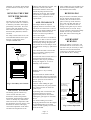
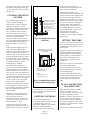
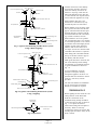
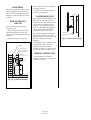
INSTALLATION INSTRUCTIONS FOR THE CHARNWOOD LA30iB HEALTH AND SAFETY PRECAUTIONS Please take care when installing the appliance that the requirements of the Health and Safety at Work Act 1974 are met. Some types of fire cement are caustic and should not be allowed to come into contact with the skin. In case of contact wash with plenty of water. If there is a possibility of disturbing any asbestos in the course of installation then please use appropriate protective equipment. There must not be an extractor fan fitted in the same room as the fire as this can cause the appliance to emit fumes into the room. There must be an adequate air supply into the room in which the appliance is installed totalling at least 100 square cm. (16 square inches) to provide combustion air. This is particularly necessary if the room is double glazed. In addition to these instructions the requirements of BS:8303 and BS:6461 Pt 1&2; 1984 must be fulfilled. Local Authority Byelaws and Building Regulations regarding the installation of Solid Fuel burning appliances, flues and chimneys must also be observed. PERFORMANCE The rated output for the LA30iB is 6.1 kW (20,800 btu/h) to water and 2.7 kW (9,200 btu/h) to the room. These are the outputs obtained during testing in accordance with BS 3378 burning Sunbrite Doubles with the doors closed over a 4 hourly re-fuelling interval. If the optional boiler reduction brick is fitted and the deepening bar removed then the output is reduced to 3.0 kW (10,200 btu/h) to water and 2.1 kW (7,100 btu/h) to the room. The heat output to the room is directly proportional to the heat output to water as shown in Fig. 4. This means that if the water heating load is less than the rated output then the room heating will be reduced by the same proportion. This must be borne in mind when calculating the heating requirements. CHIMNEY In order for the appliance to perform satisfactorily the chimney height must not be less than 4 metres measured vertically from the outlet of the appliance to the top of the chimney. The chimney should preferably be Boiler Output (kW) If there is no existing chimney then a prefabricated block chimney or a twin walled insulated stainless steel flue to BS:4543 can be used either internally or externally. These chimneys must be fitted in accordance with the manufacturers instructions and Building Regulations. Single wall flue pipe is suitable for connecting the fire to the chimney but is not suitable for using for the complete chimney. If it is found that there is excessive draw in the chimney then a draught stabilizer should be fitted. HEARTH 6.0 4.0 2.0 Output withboiler reduction brick fitted 0 the chimney then a lining suitable for Solid Fuel must be used. 1.0 2.0 3.0 Space Output (kW) Fig. 4. Performance Chart 175 mm (7 inches) or 200mm (8 inches) internal diameter or square with sides of 175mm or 200mm internally and MUST NOT BE LESS THAN 150mm (6 INCHES) INTERNAL DIAMETER OR 150 x 150mm INTERNAL SQUARE. If an existing chimney is to be used it must be swept and checked, it must be in good condition, free from cracks and blockages, and should not have an excessive cross sectional area (eg. greater than 250mm x 250mm). If you find that the chimney is in poor condition then expert advice should be sought regarding the necessity of having the chimney lined. If it is found necessary to line Page 7 LA30iB 3.99 The appliance must be installed on a fireproof hearth and must be situated at least 300 mm (12 inches) from any combustible material. The positioning of the appliance and the size of the hearth are governed by building regulations for Class 1 appliances. These building regulations state that the hearth must extend in front of the appliance by at least 300 mm (12 inches) and to the sides of the appliance by at least 150 mm (6 inches). If in doubt as to the positioning of the appliance expert advice should be sought either from the supplier or the local building inspector. PREPARATION OF FIREPLACE Before fitting the appliance into an existing fireplace remove the fireback and any loose in-fill material. The hearth, surround and opening for the appliance must conform with Figs. 5 and 6. The flat area around the opening must be a minimum of 750 mm wide and 660 mm high. Ensure that the hearth and the base in the opening are flat, level, and at right angles to the surround. Make two holes in the chimney breast, one in the front to give access for infilling and fixing the flue pipe, and one in the side to give access for the pipework. work in conjunction with the thermostat on the appliance and the minimum return thermostat. CENTRAL HEATING SYSTEM The central heating system must comply with BS:5449 part 1. If the system is to be a combined heating and domestic hot water system then a double feed indirect hot water storage cylinder to BS:1566 part 1 should be used. In order to prevent the build up of scale and corrosion a suitable inhibitor should be used. The system must be correctly vented as shown in Figs. 7 and 8. The height differential between the header tank and the appliance must not exceed 15.2 metres (50 feet). If all four boiler tappings are used then, if possible, diagonal pairs should be connected for domestic hot water and central heating. Where a common return is used an injector tee must be incorporated into the system as shown in Fig. 9. This will ensure that a good domestic hot water supply is maintained when the central heating pump is operating. The system must incorporate a gravity circuit which will normally heat the domestic hot water and an unvalved radiator with an output of at least 0.75 kW. When the appliance is not connected to a domestic hot water system the unvalved radiator(s) on the gravity circuit must have an output of at least 1.0 kW. This is to prevent boiling in case of pump failure. If the boiler reduction brick is fitted then the appliance may be used for room heating and supplying domestic hot water without the need for a gravity radiator. All pipework in the primary circuit must be 28 mm diameter and the gravity flow pipe must rise continuously from the boiler to the open vent. Two typical systems are shown in Figures 7. and 8. If the fire is used to heat a small central heating system then the heat output to the room from the fire will This Dimension Is The Minimum Level Area Required To Enable The DoorsTo Be Opened. For Overall Sizes Of Hearth SeeThe Section Titled "Hearth". 405 mm 400 mm Minimum Fig. 5. Limiting Dimensions of Hearth We recommend fitting a pipe thermostat onto the gravity return and wiring it into the mains supply to the pump so that if the gravity return temperature drops below 45° C then the pump will cut out. This will help to prevent condensation forming on the boiler faces and will thereby increase the life of the boiler. Use of a minimum return thermostat also ensures that priority is given to the domestic hot water. These thermostats are available from ourselves if you are unable to obtain them locally. FITTING THE FIRE In some cases it may be necessary to place the connecting flue pipe in the chimney before fitting the fire into the fireplace. The shaded area on the face of the surround is the minimum flat area required. 750 mm 660 mm B A Dim.A: Max.470mm(18 - 1/2") Min.405mm(16") Dim.B: Max.575mm(22 - 2/3") Min.555mm(21 - 3/4") Fig. 6. Limiting Dimensions of Surround and Opening Apply fire cement to the rear face of the sealing flange on the appliance. Fit the appliance into the opening ensuring that it is central and that a good seal is made between the sealing flange and the face of the surround. Remove any excess fire cement from around the sealing flange. The fire should be screwed to the hearth through the holes at the base of the sealing flange. Connect the heating system to the boiler ensuring that the primary flow pipe rises from the fire. Fill the system with water and check for leaks. FLUE CONNECTION AND INFILLING be reduced. Fig. 4. shows the ratio of space heating to water heating which can be expected. SYSTEM CONTROLS The circulating pump may be controlled by means of time switches, room thermostats or outdoor thermostats. Radiators may be either manually or thermostatically controlled. These controls will all Page 8 LA30iB 3.99 Make the flue connection with the special 150° elbow part no. 010/AV12. Please note that this item is ordered separately from the appliance. The legs of the elbow may be cut on site to suit the chimney. Also note that the legs of the elbow are different lengths to enable some situations to be catered for by turning the elbow around. The end of the flue pipe must line up 22mm Open Vents Feed and Expansion Tank Cold Water Tank Overflow Overflow Domestic Hot Water Draw Off with the centre-line of the chimney, and must also extend to the point where the chimney narrows to its final size. Any large voids must be filled and flaunched to the flue pipe to ensure that all soot deposits can be cleared when the appliance is swept. Ensure that the flue pipe is not obstructed or restricted in any way and that all joints are well sealed. Gravity Radiator Drain Cock Indirect Hot Water Cylinder Central Heating Flow Minimum Return Thermostat Circulating Pump Central Heating Return Drain Cock at Lowest Point Fig. 7 Typical Central Heating and Hot Water System Using 4 Boiler Tappings Before infilling cover the front of the fire to protect it. Ensure that the flue pipe is central and then fill the space between the body of the fire and the structural brickwork with vermiculite (eg. micafil or similar) concrete. Ensure that there are no air pockets. The recommended mix is six volumes of vermiculite granules to one volume of portland cement thoroughly mixed together. Enough water should be added so that no more than one or two drops of water are released when a handful of the mixture is squeezed. 22mm Open Vents Feed and Expansion Tank Cold Water Tank Overflow Overflow Domestic Hot Water Draw Off Gravity Radiator Drain Cock Indirect Hot Water Cylinder Minimum Return Thermostat After filling with vermiculite flaunch the top of the flue connector pipe to the chimney with lime mortar. Make good the holes in the front and side of the chimney breast making sure that they are completely airtight. A typical installation is shown in Fig. 10. In most installations it will be possible to sweep the chimney through the appliance. If this is not possible then some alternative means (such as a soot door), must be provided. Central Heating Flow Circulating Pump The free-inset method of installation may be used instead of in-filling. Details are available on request. Central Heating Return Drain Cock at Lowest Point Injector Tee Fig. 8. Typical Central Heating & Hot Water System Using 3 Tappings Gravity Return (28mm Pipe) Central Heating Return Common Return to Boiler (28mm Pipe) Fig. 9. InjectorTee. Page 9 LA30iB 3.99 THERMOSTAT Before lighting the fire check the cold setting distance of the thermostat. With the control knob at the maximum setting the flap should be 18 mm from the air inlet as shown in Fig. 11. To adjust the distance slacken the locking nut and adjust as necessary. When set correctly re-tighten the locking nut. Ensure that the flap opens and closes freely as the knob is turned. ASSEMBLY back of the grate must be in position and sitting correctly. Fit the side panels, hood and top grid onto the appliance. Instructions for this are enclosed with the panel pack. 3. The throat plate must be fitted in the roof of the appliance. 18mm Replace any internal parts previously removed. PRE LIGHTING CHECK Before initial lighting check the following points: 1. The bottom grate bars must all be fitted and should move freely and easily when the riddling mechanism is operated. 2. The plates round the sides and Flaunching Take Flue Pipe Up To Narrowest Part Of Chimney. 150° Elbow Part No. 010/AV12 150° Vermiculite Infill COMMISSIONING On completion of the installation and after allowing a suitable period of time for the fire cement and mortar to dry out, the fire should be lit and checked to ensure that smoke and fumes are taken from the appliance up the chimney and emitted safely. Also check all joints and seals. LockingNut The central heating pump should be adjusted to give the correct water flow against the circuit resistance and the system should be correctly balanced. On completion of the installation and commissioning please leave the operating instructions with the customer and advise on the use of the fire and any controls on the system. FREESTANDING KIT A freestanding kit is available. Details of dimensions and outputs are available on request. Fig. 10. Typical Installation Page 10 LA30iB 3.99 Thermostat Flap Fig. 11. Thermostat Setting 394 154 i/d 235 Boiler tappings are 1" B.S.P. female. Two each side. FLUE C L 150° 619 547506 405 265 200 235 59 554 120 164 Charnwood LA30iB Overall Dimensions (Dimensions are in mm) Page 11 LA30iB 3.99 Issue G CHARNWOOD LA30iB PARTS LIST 48 47 49 41 32 34 18 31 38 45 46 Freestanding Kit 40 37 33a 20 27 19 21 26 12 17 16 7 5 36 33 42 30 15 39 14 13 28 29 23 Item Part No. 19 25 Description 24 24 9 8 35 Item Part No. 11 Nuts, bolts, screws and clips are not shown for clarity. To obtain spare parts contact your local stockist giving model, part no. and description. In case of difficulty contact the manufacturer at the address shown below. This drawing is for 10 identification purposes only. Description 1* 008/RW35L L.H. Door Seal 26 012/FW14 Riddler Rod 2* 008/RW35R R.H. Door Seal 27 012/CG05 Idler Rod 3* 008/RW35/S Door Seal Set Incl. Adhesive 28 008/FW48 Thermostat C/W Flap 4* 008/FW29 Door Seal Adhesive 29 008/BW57 Thermostat Flap 90mm Dia 5 006/RW18 Glass Inc Glass Channel 30 005/RW05 Side Panel L.H. 6* 008/RW44/S Glass Channel Set Of 8 31 005/RW04 Side Panel R.H. 7 004/EW23 Glazing Bar 32 005/RW06 Hood Panel 8 008/FW27 Hinge Post Main Door 33 004/RW13 Panel Fixing Bracket 9 008/BW39/S Hinge Pin Main Door Set (4) 33a 012/RW30 Hood & Panel Fixing Kit 10 008/RW43/A Door Catch Assembly R.H. 34 008/WW14S Hood Fixing Pin Set (4) 11 002/BW12 Door Knob L.H. 35 003/RW01 Door L.H. 12 002/CG06 Riddler Knob 36 003/RW02 Door R.H. 13 002/BW20 Riddler/Ashpan Tool 37 009/LA30IB/A LA30iB Firebox / Boiler Assy 14 002/BW26 Door Opening Tool 38 011/AV09 Boiler Reduction Brick (Optional Extra) 15 008/BW50 Thermostat Knob 39 012/FW34 Scraper Tool 16 002/FW07 Front Firebar 40 012/RW09 Secondary Air Flap 17 002/FW08 Deepening Bar 41 010/AV12 150 ° Flue Pipe (Optional Extra) 18 002/AV31 Throat Plate 42 012/AV11B Serial Number Label 19 002/HW15 Side Fire Plate 43* 010/EW51 Ash Carrier (Optional Extra) 20 002/HW16 Back Fire Plate 44* 008/TH02/L Low Level Pipe Stat (Optional Extra) 21 002/CG01 Bottom Grate Bar 45 005/AV23 Side Panel L.H. (Freestanding Kit) 22 002/CG01S7 Set Of Grate Bars 46 005/AV24 Side Panel R.H. (Freestanding Kit) 23 004/EW17 Ashpan 47 005/AV22 Hood Panel (Freestanding Kit) 24 002/HW30 Carrier Bar 48 002/AV13 150° Flue Elbow (Freestanding Kit) 25 012/HW33 Mover Bar 49 010/AV26 Rear Panel Bracket (Freestanding Kit) * These items are not shown on the drawing. Bishops Way, Newport, Isle Of Wight, PO3O 5WS Tel: (01983) 527552 Fax: (01983) 821267