1
S__A/_S
OWNER'S
MANUAL
MODEL NO,
917,242440
£RIIFT$ I:IN+'
Caution:
Read and follow
all Safety Rules
and Instructions
Before Operating
This Equipment
ELECTRIC LIFT
ACTUATOR KIT
for GARDEN TRACTORS
• Assembly
• Operation
• Customer
Responsibilities
• Repair Parts
Sears, Roebuck and Co., Chicago, IL 60684 U.S.A.
SAFETY
Safe Operation
Practices RULES
for Ride-On Mowers
IMPORTANT: THIS CUTTING MACHINE IS CAPABLE OF AMPUTATING HANDS AND FEET AND THROWING
OBJECTS. FAILURE TO OBSERVE THE FOLLOWING SAFETY INSTRUCTIONS COULD RESULT IN SERIOUS
INJURY OR DEATH.
I.
GENERAL OPERATION
•
•
•
•
•
•
•
•
•
•
•
•
•
•
•
I1.
IlL CHILDREN
Read, understand, and follow all instructionsin the manual
and on the machine before starting.
Only allow responsible adults, who are familiar with the
instructions,to operate the machine.
Cleartheareaofobjeotesuch as recks, toys,wire, etc., which
could be picked up and thrown by the blade.
Be surethe area is clear of otherpeople beforemowing. Stop
machine if anyone enters the area.
Never carrypassengers.
Do not mow in reverse unlessabsolutelynecessary. Always
look down and behind before and while backing.
Be aware of the mower discharge directionand do not point
it at anyone. Do not operate the mower without either the
entire grass catcher or the guard in place.
Slow down before turning.
Never leave a running machine unattended. Always turnoff
blades, set parking brake, stop engine, and remove keys
before dismounting.
Turn off bladeswhen not mowing.
Stop engine before removing grass catcher or unclogging
chute.
Tragic accidents can occur if the operator is not alert to the
presence of children. Childrenare oftenattracted to the machine
andthe mowingactivity. Neverassume that children will remain
where you last saw them.
•
•
•
•
•
•
•
Mow only in daylight or good artificiallight.
Do not operate the machine while under the influence of
alcohol or drugs.
Watch for trafficwhen operating near or crossingroadways.
Use extra care when loading or unloadingthe machineinto a
trailer or truck.
•
•
SLOPE OPERATION
•
•
•
•
•
•
Mow up and down slopes, not across.
Remove obstacles such as rocks,tree limbs, etc.
Watch for holes, ruts, or bumps. Uneven terrain could
overturnthe machine. Tall grass can hide obstacles.
•
Use slow speed. Choose a low gear sothat youwill not have
to stop or shiftwhile on the slope.
•
Followthemanufactureer's
recommendations forwheel weights
or counterweightsto improve stability.
•
Use extra care with grass catchers or other attachments.
These can change the stabilityof the machine.
•
Keep all movement on the slopes slow and gradual. Do not
make sudden changes in speed or direction.
•
Avoid startingor stopping on a slope. If tires lose traction,
disengage the blades and proceed slowly straightdown the
slope.
DO NOT:
•
•
•
•
Do not turnonslopes unlessnecessary,andthen, turnslowly
and gradually downhill,if possible.
Do not mow near drop-offs, ditches,or embankments. The
mower couldsuddenlyrum over if a wheel is over the edge of
a cliff or ditch,or if an edge caves in.
Do not mow on wet grass. Reduced traction could cause
sliding.
Donottrytostabilizethemachinebyputtingyourfootonthe
ground.
Do not use grasscatcher on steep slopes.
Never carry children. They may fall off and be seriously
injured or interfere with the safe machine operation.
Never allow childrento operate the machine.
Use extra care when approaching blind corners, shrubs,
trees, or other objects that may obscure vision.
IV. SERVICE
Slopes are a major factor related to loss-of-controland tipover
accidents, which can result in severe injury or death. All slopes
require extra caution. If youcannot backup the slopeor ifyoufeel
uneasy on it, do not mow it.
DO:
•
Keep childrenoutofthe mowingarea andunderthe watchful
care of another responsible adult.
Be alert and turn machine off if children enter the area.
Before and when backing, look behind and down for small
children.
•
•
•
•
Use extra care in handling gasoline and other fuels. They
are flammable and vapors are explosive.
Use only an approved container.
Never remove gas cap or add fuel with the engine
running. Allow engine to cool before refueling. Do not
smoke.
Never refuel the machine indoors.
Never storethe machine or fuel container inside where
there is an open flame, such as a water heater.
Never run a machine inside a closed area.
Keep nuts andbolts,especiallyblade attachment bolts,tight
and keep equipment in good condition.
Never tamper with safety devices. Check their proper
operation regulady.
Keep machinefree of grass,leaves, or other debris build-up.
Clean. oil or fuel spillage. Allow machine to cool before
storing.
Stop and inspect the equipment if you strike an object.
Repair, if necessary, before restarting.
Never make adjustments or repairs withthe engine running.
Grass catcher components are subject to wear, damage,
and deterioration,whichcould expose movingparts or allow
objects to be thrown. Frequently check components and
replace with manufacturer'srecommended parts, when necessary.
Mower blades are sharp and can cut. Wrap the blade(s) or
wear gloves, and use extra caution when servicing them.
Check brake operation frequently. Adjust and service as
required.
Look for this symbol to point out important safety precautions.
It means
CAUTION!!! BECOME ALERT!!! YOUR
SAFETY IS INVOLVED.
&
2
CAUTION: Always disconnect spark
plug wire and place wire where it cannot
contact spark plug in order to prevent
accidental starting when setting up,
transporting,
adjusting or making
repairs.
CONGRATULATIONS on yourpurchase of a Sears Electric Lift Actuator Kit. It has been designed, engineered
and manufactured to give you the best possibledependabilityand performance.
Should you experience any problemsyou cannot easily
remedy, please contact your nearest Sears Service Center/Department. We have competent, well trained technicians and the proper tools to service or repair this unit.
Please read and retain this manual. The instructionswill
enable you to assemble and maintain your Lift Kit properly. Always observe the "SAFETY RULES".
CUSTOMER
RESPONSIBILITIES
• Read and observe the safety rules.
• Follow a regular schedule in maintaining, caring for
and using your Electric lift kit.
• Follow the instructions under "Operation" and "Customer Responsibilities"sectionsof this Owner's Manual.
MODEL
NUMBER 917.242440
SERIAL
NUMBER
DATE OF
PURCHASE
THE MODEL AND SERIAL NUMBERS WILL BE
FOUND ON A DECAL LOCATED IN THE BAG
OF PARTS. ATTACH DECAL TO YOUR TRACTOR FOR FUTURE REFERENCE.
YOU SHOULD RECORD BOTH SERIAL NUMBER
AND DATE OF PURCHASE AND KEEP IN A SAFE
PLACE FOR FUTURE REFERENCE.
LIMITED ONE YEAR WARRANTY ON
CRAFTSMAN ATTACHMENTS
For one year from the date of purchase, when this electric lift attachmentis maintainedaccording to the operating and
maintenance instructionsinthe owner'smanual, Sears will repairfree ofcharge anydefect in material or workmanship.
This warranty does not cover:
•
•
•
Expendable items which become worn during normal use.
Repairs necessary because of operatorabuse or negligence, includingthe failure to maintain the equipment
according to instructionscontained in the owner's manual.
Attachments used for commercial or rental purposes.
WARRANTY SERVICE IS AVAILABLE BY RETURNING THE CRAFTSMAN ELECTRIC LIFT KIT TO THE NEAREST
SEARS SERVICE CENTER/DEPARTMENT IN THE UNITED STATES. THIS WARRANTY APPLIES ONLY WHILE
THIS PRODUCT IS IN USE IN THE UNITED STATES.
This warranty gives you specific legal rights, and you may also have other rights which vary from state to state.
SEARS, ROEBUCK AND CO., D/817 WA, HOFFMAN ESTATES, ILLINOIS. 60179
TABLE OF CONTENTS
SAFETY RULES ............................................................ 2
WARRANTY ................................................................... 3
PARTS ORDERING/SERVICE ..................................... 3
CARTON CONTENTS ............................................... 4-6
COMMON SET-UP ........................................................ 7
GEAR DRIVE REAR ASSEMBLY ................................. 8
HYDRO REAR ASSEMBLY .......................................... 9
ASSEMBLY TO VERT. ENGINE GT ...................... 10-13
ASSEMBLY TO HORZ. ENGINE GT .......................... 14
ELECTRICAL ASSEMBLY ..................................... 15-16
OPERATION ................................................................ 17
CUSTOMER RESPONSIBILITIES .............................. 17
REPAIR PARTS ..................................................... 18-22
3
BEFORE
YOU START TO ASSEMBLE
THE ELECTRIC
LIFT KIT
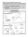
This electric lift kit is designed for all garden tractors, with horizontal shaft or vertical shaft engines, and gear drive or
hydrostatic type transaxles. Before you start to lay out the contents, you must first determine if you have a horizontal or
vertical shaft engine and a gear drive or hydrostatic type transaxle in your tractor. Once you have this information, layout
only those parts which will be used for your type of tractor according to "CARTON CONTENTS" section of this manual.
NOTE: KIT ASSEMBLY WILL REQUIRE ALL COMMON PARTS AND ONLY THOSE PARTS GROUPED FOR YOUR
PARTICULAR TYPE TRACTOR.
ALL REMAINING PARTS MAY BE DISCARDED.
1) VERTICAL OR HORIZONTAL ENGINE CAN BE DETERMINED BY POSITION OF THE ENGINE PULLEY,
IF PULLEY IS UNDER THE ENGINE IT IS A VERTICAL TYPE ENGINE, IF PULLEY IS IN FRONT OF ENGINE IT IS A
HORIZONTAL TYPE ENGINE.
2) HYDROSTATIC TRANSAXLE. CAN BE DETERMINED BY INFINITE SPEED CONTROL POSITIONS, AND
GEAR DRIVE TRANSAXLE WILL HAVE RESTRICTED SPEED GEAR SE'n'INGS.
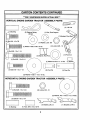
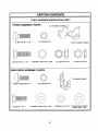
CARTON
***ONLY
COMMON
ASSEMBLY
HARDWARE
CONTENTS
SHOWN
ACTUAL
SIZE***
PARTS
(1) Hub, Lever Lift
(1) Actuator
(1) Bolt 3/8 - 16 x 1-3/8
0
0
(1) Actuator
COMMON
ELECTRICAL
O0
I
(3) Retainer Spring
(Large)
Pin
PARTS
Q
O
(1) Washer, Lock Int. Tooth
(2) Hex Facenut
(1) Clip, Insulated
(1) Lift_
(1) Wire Harness
(1) GroundWire
4
(1) Washer 15/32 x 3/4 x 16 Ga.
CARTON CONTENTS
***ONLY
VERTICAL
HARDWARE
ENGINE GARDEN
(1) Bushing
SHOWN
TRACTOR
i_ -_
CONTINUED
ACTUAL
SIZE***
ASSEMBLY
PARTS
_ j))
(2) LiftLink
(2) Retainer Spring
(Small)
(1) Rod, Pivot Support
_.._
(1) Bracket,
P_vot_
(1) Washer 13/32 x 7/8 x 16 Ga.
(1) Bolt 318- 16 x 1-1/4
(4) Locknut 3/8 - 1
I
I
1
',
I
I
I
I
(2) Nyliner, Rod Pivot
(1) Pivot Arm
(1) Bolt 3/8 - 16 x 2-1/4
(1) Washer21/32 x 1 x 21 Ga.
(2) Pivot Pin
(1) Spacer
(1) Pivot Pin
(2) Washer 11/32 x 1-1/2 x 10 Ga.
HORIZONTAL
_(1)
ENGINE GARDEN
TRACTOR
ASSEMBLY
r IIIJIllfl
II
Bolt 3/8 - 16 x 1-3/4
(2) Locknut 3/8- 16
(5) Washer, Flat 17/32 x 1-1/2 x 10Ga.
(1) Bolt 3/8 - 16 x 2-1/4
1
(1) Bushing
iI
(1) Tube .384 x 1/2 x 15/16
(1) Bracket, Lift L.H.
(1) Bracket, Lift R.H.
CARTON CONTENTS
***ONLY HARDWARE SHOWN ACTUAL SIZE***
HYDRO
ASSEMBLY
PARTS
(1) LH.Actuator
G
(1) Locknut3/8-16
(1) Bolt 3/8-16 x 1-1/4
(1) R.H. Actuator, Bracket
GD
(1) Washer 17/32 x 3/4 x 16 Ga.
(2) Bolt 7/16-14 x 1-1/4
GEAR
DRIVE ASSEMBLY
(1) Jam nut 7/16-14
PARTS
G
(2) Bolt Carraige 3/8-16 x I
(1) Locknut7/16-14
0
(1) Actuator, Bracket
(2) Locknut3/8-16
,J
%
(1) Bolt 3/8 -16 x I
(1) Washer 13/32 x 7/8 x 16 Ga.
6
(1) Washer, Lock 3/8
(1) Thick Spacer Washer
13/32 x 7/8 x 7 Ga.
/
COMMON SET-UP
(1)
(1)
(2)
(1)
(1)
(1)
THESE ARE THE TOOLS YOU
WILL NEED FOR ASSEMBLY.
i
3/16" Allen Wrench
1/2" Wrench
9/16" Wrenches
5/8" Wrench
11/16" Wrench
Fiat Blade Screwdriver
(1)
(1)
(1)
(1)
(1)
(1)
9/16" Socket
5/8" Socket
11/16" Socket
Drive Ratchet
3" or longer Extension
Phillips Screwdriver
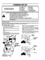
CAUTION: BEFORE ASSEMBLING ACTUATOR KIT TO TRACTOR:
Depress clutch/brake pedal fully and set parking brake.
Place gearshift/motion control lever in "NEUTRAL" position.
Place attachment clutch in "DISENGAGED" position.
Turn ignition key "OFF" and remove key.
Make sure the blade and all moving parts have completely stopped.
Disconnect spark plug wire from spark plug and place wire where it cannot come in
contact with plug.
NOTE: When right hand (R.H.) and left hand (L.H.) are mentionedinthis manual, it means when you are seated on the tractor,
in the operator'sposition.
NOTE: THE ILLUSTRATIONS SHOWN IN THIS MANUAL ARE TO AID IN THE ASSEMBLY AND OPERATION OF THIS
KIT. THEY MAY OR MAY NOT SHOW YOUR PARTICULAR TRACTOR MODEL.
SET-UP
(See Figs. 1,2 & 3)
•
•
Remove mower deck if installed(referto your "Tractor
Owner's Manual" for instructions).
•
Remove cap, E-Ring, and washerfrom axle on left rear
wheel.
•
Place a suitable size block of wood under drawbar
bracket.
•
Remove rear wheel.
•
ON BAND BRAKE MODELS ONLY: Remove hex bolt,
Iockwasher and flat washer indicated by arrow, from
transaxle and discard.
•
•
Relieve any tension on attachment lift spring by
loosening jam nut and adjustment bolt.
Remove socket/hex head screw from lift control lever.
Remove lift lever and washers (if equipped).
NOTE: Use block of wood to assist in lift handle
removal. Save washers for later use.
Install washers, if removed earlier, on lift lever ]]ub. Fit
lift lever hub on splined lift shaft and secure with
3/8-16 x 1-3/8 hex bolt, provided with kit.
LIFT
JAM
NUT
LEVER
SOCKET HEAD/
HEX HEAD
SCREW
O
DRAWBARo(
QBRACKET
Q
Q
WASHERS
(IFEQUIPPED)
ATrACHMENT
LIFT SPRING
BOLT
Fig. 2
"FOR BAND
BRAKE MODELS
ONLY"
WASHERS
(IF EQUIPPED)
LIFT
LEVER
HUB
HEX BOLT
HEX BOLT
LOCKWASHER
AND FLATWASHER
SPLINED
LIFT SHAFT
Fig. 1
7
Fig. 3
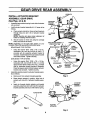
GEAR DRIVE REAR ASSEMBLY
LOCKNUTS
INSTALL
ACTUATOR
BRACKET
ASSEMBLY, GEAR DRIVE
(See Figs. 4,5 & 6)
•
Assemblelarge retainer springinouter holeof actuator
pin as shown.
•
Install actuator bracket assembly to LH. frame rail as
follows.
a.
ACTUATOR
BRACKET
ASSEMBLY
Place actuator bracket on frame rail and insert pin
through holes (C) and (D) of actuator bracket
assembly.
NOTE: Inserting pin gives proper alignment of
holes for installingelectric actuator.
L.H. FRAME
RAIL
b. Secure bracket to frame rail using two carriage
bolts, and Iocknuts as shown.
THICK SPACER WASHER
NOTE: Depending on the type brake system on your
transaxle, follow the appropriate instructionsbelow.
BRAKE BAND TYPE SYSTEM
•
Using flat washer (thin) 13/32 x 7/8 x 16 Ga.,
Iockwasher 3/8, and hex bolt 3/8-16 UNC x 1,
provided with kit, assemble actuator bracket to
transaxle. Installhardwarethroughactuatorbracket
and brake bracket. Tighten securely.
m
I
Using flat washer (thin) 13/32 x 7/8 x 16 Ga.,
Iockwasher 3/8, hex bolt 3/8-16 UNC x 1, and flat
Spacerwasher (thick) 13/32 x 7/8 x 7 Ga., provided
with kit, assemble actuator bracket to transaxle.
Place flat spacer washer (thick) between actuator
bracket and transaxle. Tighten securely.
Assemble electric actuator to actuator bracket assembly as follows.
b.
Place electric actuator in position. Align hole of
actuator with hole (C) of actuator bracket assembly.
c.
Insert pin through electric actuator and bracket
assembly. Align hole of pin with hole (E) in actuator
bracket assembly and secure with retainer spring.
PIN
;LARGE RETAINER
SPRING
\w,s
•
Remove pin from actuator bracket assembly.
LOCKNUTS
_D
DISK BRAKE TYPE SYSTEM
a.
A
(13/32 X 7/8 X 7 GA)
OR
BRAKE BRACKET
_,, _J
BRACKET
HEX BOLT
I
_ r
Fig. 5
LARGE
RETAINER
ACTUATOR
tKET
ASSEMBLY
SPRING
LARGE
ACTUATOR PIN
LARGE
RETAINER
SPRING
II
|
SPRING
J
ELECTRIC
ACTUATOR
Fig. 4
Fig. 6
8
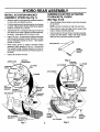
HYDRO REAR ASSEMBLY
INSTALL
ACTUATOR
ASSEMBLY,
HYDRO
(See Fig. 7)
•
Remove upper hex bolt securingtransaxle bracket to
LH frame rail, as indicated by arrow.
•
Fit leftand rightactuatorbracketstogether,bent bracket
to inside. Slide actuator bracket assembly up against
inside of LH frame rail, as shown.
•
•
•
•
ASSEMBLE ELECTRIC ACTUATOR
TO BRACKETS, HYDRO
(See Figs. 8 & 9)
BRACKET
•
Assemble largeretainer springinouter hole ofactuator
pinas shown.
NOTE: use end of actuator pin with only one hole.
Assemble 3/8-16 x 1 carriage boltthroughLH frame rail
and upper corner holes of actuator bracket assembly,
as shown. Hand tighten 3/8-16 Iocknuton bolt.
Insert7/16-14 x 1-1/4 hexboltfrom insidetractorframe
rails through RH actuator bracket, drawbar, LH frame
rail and transaxle bracket as shown. Hand tighten
Iocknut on hex bolt
While holding jamnut on inside of actuator bracket
assembly, insert remaining 7/16-14 x 1-1/4 hex bolt
from outside through transaxle bracket, LH frame rail
and actuatorbracket assembly and thread intojamnut,
as shown.
•
Place actuator in place and align hole in actuator with
holes in actuator bracket assembly.
•
Insertactuatorpin through holes in bracket assembly,
actuator and flat washer. Retain with large retainer
springat inner most hole locationas shown.
ACTUATOR PIN_
LARGE
RETAINER
SPRING
Tighten all hardware securely.
JAMNUT (THIN)
Fig. 8
HEX BOLT
INSIDE)
ELECTRIC
ACTUATOR
FLATWASHER
LH. FRAME
RAIL
L.H. FRAME
RAIL
ACTUATOR PIN
R.i
ACTUATOR
BRACKET
SKID BRACKET
R.H. ACTUATOR
BRACKET"
ELECTRIC
ACTUATOR
_EMOVE HEX
BOLT AND
DISCARD
ACTUATOR
BRACKET
©
.TRANSAXLE
BRACKET
LARGE
RETAINER
SPRING
L.H. ACTUATOR
BRACKEI
Fig. 7
ACTUATOR PIN
FLATWASHER
9
Fig. 9
LARGE
RETAINER
SPRING
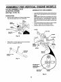
ASSEMBLY
FOR VERTICAL
ENGINE MODELS
LIFT KIT ASSEMBLY TO GT
w/VERTICAL
ENGINE
ASSEMBLE
(See Figs. 10 thru 16)
•
PREPARATION
•
Remove height indicatoron LH side of tractor frame.
Save all parts except hex bolt for reassembly.
FLAT
WASHER
HEIGHT
INDICATOR
•
7
-
•
PIVOT ARM ASSEMBLY
Assemble bothlift links between sides of pivot arm as
shown. Secure with larger pivot pin and small retainer
spring.
NOTE: Slots in lift linksare not centered and must be
assembledcorrectly.To assemble hold pivotarmwith
bent end towards you and downwards. Position lift
linkssoslot isto leftand narrow edge isat bottom(see
inset)
Place spacer between the two links and insertsmaller
pivotpin. Secure with small retainer spring.
Installtwo nylinersinto pivot bracket as shown.
LOCK
WASHER
HEX BOLT
NYLINER
PIVOT ARM
SNAP-OUT
COVER
FLAT
WASHER
NYLINER
Fig. 10
LIFT LINKS
0
Slide 21/32 x 1 x 21 Ga. washer onto pivot rodsupport
up to nibs. Set aside for later use.
SMALL
RETAINER
SPRINGS
LARGER
PIVOT PIN
NIBS
SPACER
PIVOT ROD
SMALLER
PIVOT PIN
SUPPORT
21/32 X 1 X 21 GA.
WASHER
Fig. 11
BE SURE SLOT IS
TO LEFT AND
NARROW EDGE IS
TO BOI-rOM
BENT END OF
PIVOT ARM
INSET
Fig. 12
10
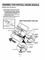
ASSEMBLY
ASSEMBLE
FOR VERTICAL
ENGINE MODELS
PIVOT ROD BRACKET
Install pivot rodbracket to insideof R.H. frame fail'using
two hex bolts3/8-16 x 7/8 and two 3/8-16 Iocknuts.
1.
Be sure parking brake isengaged. Positionpivot
rod bracket to inside of R.H. frame rail and install
one hex boltthrough upper mountinghole._Jnstall
Iocknuton hex bolt to outside of frame rail.
2.
Disengage parking brake, and install remaining
hex boltand Iocknut as shown.
Tighten hardwaresecurely. Be sureto engage parking
brake after pivot rod bracket is installed.
VIEW FROM UNDER TRACTOR
PIVOT ROD BRACKET
3/8-16 LOCKNUT
318-16 X 718
BOLT
UPPER
.MOUNTING
HOLE
1
PARKING
BRAKE
DISENGAGED
ROD BRACKET
3/8-16 X 718
HEX BOLT
PARKING BRAKE
ENGAGED
Fig. 13
11
RIGHT HAND
FRAME RAIL
_,RIGHT HAND
FRAME RAIL
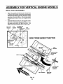
ASSEMBLY
FOR VERTICAL
ENGINE MODELS
INSTALL PIVOT ARM ASSEMBLY
Raise link assembly until nylinersare in4inewith hole
in LH side oftractorframe. Insertpivotrodsupportwith
washerthroughnylinersinpivotarm, as shown.Loosely
assembly to hex bolt 3/8-16 x 718 and lock washer
through holein LH side offrame. Do not tightenat this
time.
Assemble flattened end of pivot rod supportto underside of pivot rod bracket usinghex bolt3/8-16 x 1-1/4,
flat washer and Iocknut and tighten securely. Now
tighten previouslyassembled 3/8-16 x 7/8 hex bolt.
318-16 X 718
HEX BOLT
LOCK
WASHER
NYUNERS AND
PIVOT ARM
3/8-16 X 1-1/4
HEX BOLT
FLAT
WASHER
VIEW FROM UNDER TRACTOR
3/8-16 X 7/8
HEX BOLT
LOCK
HOLE IN LH SIDE
OF TRACTOR
FLAT
PIVOT ROD BRACKET
NYLINERS AND
PIVOT ARM
ASSEMBLY
318-16 LOCKNUT
Fig. 14
12
PIVOT ROD
SUPPORT
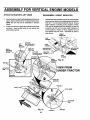
ASSEMBLY
ATTACH ACTUATOR
FOR VERTICAL
& LIFT LINKS
ENGINE MODELS
REASSEMBLE
1
Insertactuatorarm and bushingbetween pivotarmsas
shown.Secure with3/8-16 x 2-1/4 hexbolt and Iocknut.
NOTE: Be sure that bolt is assembled in direction
shown.
2
Positionone lift linkon each side ofthe liftshaftbracket
as shown. Insert smaller pivot pin and secure with
small retainer spring.
HEIGHT
INDICATOR
Reassemble heightindicatorpreviouslyremoved addingtwo spacer washers and replacing hex boltwith the
5/16-18 x 1-1/4 hex bolt providedwith this kit. Ensure
height indicator is showing correct position of deck.
This may be adjusted after final assembly of deck by
loosening hex bolt and moving height indicator to
correct positionin relationto deck, retighten hex bolt
and replace snap-out cover. Assemble all parts in
order shown.
HEIGHT
INDICATOR
FLAT
WASHER
LIFT UNK
LIFT
SHAFT
BRACKET
SMALL
RETAINER
SPRING _
LOCK
WASHER
(ONE ON EACH SIDE OF
LIFT
SHAFT
BRACI_'T)
NEW HEX BOLT
SMALLER
PIVOT PIN
LIFT LINK
(ONE
ON
ADD SPACER
SNAP-OUT
EACH
SIDE
OF
LIFT SHAFT BRACKET)
FLAT
WASHER
BRACKET
SMALL
RETAINER
Fig. 16
SPRING
HEX BOLT
VIEW FROM
UNDER TRACTOR
ACTUATOR
ARM
2
PIVOT PIN
HEX BOLT
PIVOT ARMS
1
ACTUATOR
ARM
Fig. 15
13
LOCKNUT
BUSHING
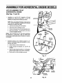
ASSEMBLY FOR HORIZONTAL ENGINE MODELS
LIFT KIT ASSEMBLY TO GT
w/HORiZONTAL ENGINE
(See Figs. 17 and 18)
•
Assemble L.H. and R.H. lift brackets to lift shaft
assembly arm using hex bolt 3/8-16 x 1-3/4, five
washers, one tube, and one Iocknutas shown.
NOTE: When assembling lift brackets, make sure top
of L.H. and R.H. brackets are positionedon lift shaft
assembly arm (offset to the right).
a.
Insert hex boltthrough R.H. lift bracket.
b. Place tube and two washers on bolt.
c.
Enter bolt through hole of liftshaft assembly arm.
d.
Place three washers, L.H. lift bracket, and Iocknut
on boltand tighten securely.
BRACKET
NOTE: The five washers are not used when assembling
lift mechanism to sleeve hitch. See your sleeve hitch
manual when installingthis electricliftactuator on tractors
so equipped.
.IFT
BRACKET
LIFT
SHAFT
ASSEMBLY
ARM
L.H. LIFT
BRACKET
R.H. LIFT
BRACKET
I
Assemble extension arm of electric actuator to L.H.
and R.H. lift brackets using hex bolt 3/8-16 x 2-1/4,
bushing,and Iocknut.
a.
LOCK'NUT
Insert bushing in hole of actuatorarm.
b. Position actuator arm between L.H. and R.H. lift
brackets.
c.
Insert hex bolt through hole (B) of L.H. lift bracket
goingthrough actuatorarm and R.H. lift bracket.
d.
Place Iocknuton bolt and tighten securely.
RS
TUBE_
Fig. 17
LIFT
HARNESS
MALE
R.H. LIFT
BRACKET
ELECTRIC
ACTUATOR
14
Fig. 18
LH. LIFT
BRACKET
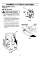
COMMON
ELECTRICAL
ASSEMBLY
WIRING ASSEMBLY FOR ALL
TRACTORS
LIFT
(See Figs. 19 thru 24)
SWITCH
BLACK
SYSTEM DISCONNECT BATrERY. REBEFORE WORKING ON ELECTRICAL
CONNECT BATrERY WHEN FINISHED.
I_
{GROUND)
WIRE
Locate the black plastic plug in upper rightor left side
of dash. Remove plug and assemble lift switch.
NOTE: Plug location may be differentthan shown.
a.
Secure one nut to lift switchas shown.
b.
Enter lift switch in dash hole (with Keyway down)
from underside of dash, placing flat washer, internal tooth Iockwasher and nut over threaded area of
lift switch. Tighten nut securely.
Fig. 20
Connect ground wire (black single wire) to lift switch.
a.
Viewing lift switch from under hood, connect black
wire to upper left hand side terminal of switch.
b.
Connect opposite end (eyelet) under the right or
left upper rear battery support nut. Support nut
(indicated by arrow) located on inside of right or left
side panel.
RIGHT OR
RIGHT OR LEFT UPPER
REAR SUPPORT BOLT
PANEL
PLUG
Fig. 21
Fig. 19
15
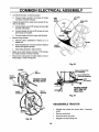
COMMON
•
Connect lift hamess to electricactuator.
a.
•
•
ELECTRICAL ASSEMBLY
Connect male connector of harness to female
connector of electric actuator.
SHIFT
GATE
COVER
Viewing lift switch from under hood connect lift harness to lift switch.
a.
Connect yellow wire of lift harness to lower right
terminal of lift switch.
b.
Connect double red wire of lift harness to lower
left terminal of lift switch.
c.
Connect single red wire to upper right terminal.
L.H. DASH
BOLT
INSULATED
Secure wiring harness.
a.
Remove Iocknut (underside of tractor) on L.H.
saddle bolt.
b.
Install insulated clip over bolt as shown. Replace
Iocknut and tighten securely.
c.
Insert wiring harness in clip as shown.
•
Raise hood, insert female connector of lift harness
into male connector of tractor harness.
•
Ensure wire routing does not allow wires to rest on
sharp edges or near moving parts.
WIRING
HARNESS
Fig. 23
(TOP)
FEMALE CONNECTOR
HARNESS)
LIFT
MALE CONNECTOR
BLACK
_RACTOR
(GROUND)
WIRE
VIEWED FROM
BEHIND DASH
HARNESS)
DASH
(CUTAWA_
O
VIEWED FROM
LEFT SIDE OF
TRACTOR
SINGLE
RED WIRE
LOWER
Fig. 24
REASSEMBLE TRACTOR
DOUBLE
RED WlRE
YELLOW
WIRE
Fig. 22
16
•
Reinstall rear wheel and mower deck, if removed
earlier.
•
Remove wood block.
•
Reconnect spark plug wire.
•
Retighten lift assist spring bolt.
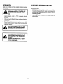
OPERATION
CUSTOMER
Make sure all Bolts and Nuts are tight, Retainer Springs
are secure.
LUBRICATION
READ THE "RULES FOR SAFE OPERATION" CAREFULLY BEFORE OPERATING YOUR ELECTRIC ACTUATOR.
J
2.
.
Ignition Switch must be "ON" to operate Electric
Actuator.
After you install LiftSwitch follow markingsalreadyon
dashboard.
2.
.
If you hear a ratcheting sound, you know you are fully
raised or fully lowered. Release Switch promptly after
ratchetingbegins.
GROU ND WHEN TURNING CORNERS,
LIFT
ATTACHMENT
OUT OF THE
REVERSING
OR TRANSPORTING.
J
THE ELECTRIC
ACTUATOR
IS
EQUIPPED WITH AN OVERLOAD CIRCUIT THAT WILL TRIP WHEN OVERLOADED.
UNIT WILL AUTOMATICALLY RESET
AFTER 10 SECONDS.
17
.
RESPONSABILITIES
The Electric Actuator is lubricated for normal life. If
Actuator is disassembled for repair, upon reassembly
lubricate with high performance extreme pressure
lubricating grease.
Apply a light coat of grease to threaded areas and
Pivot Points.
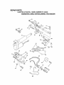
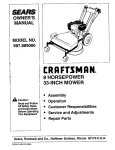
REPAIR PARTS
ELECTRIC ACTUATOR--
MODEL NUMBER 917.242440
GEAR DRIVE, HORIZONTAL
ENGINE TYPE TRACTOR
3
7
9
2
14
8
47
7
2O
31
2O
18
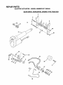
REPAIR PARTS
ELECTRIC ACTUATOR- - MODEL NUMBER 917.242440
GEAR DRIVE, VERTICAL ENGINE TYPE TRACTOR
13
15
14
2
12
31
14
24
26
34
36
/
_-/_t-JI
37 10_'@
"1_I_,_I
6
/
19
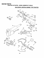
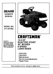
REPAIR PARTS
ELECTRIC ACTUATOR- - MODEL NUMBER 917.242440
HYDROSTATIC
DRIVE, VERTICAL ENGINE TYPE TRACTOR
14
12
31
2O
19
2O
14
42
43
35
44
20
4O
39
20
REPAIR PARTS
ELECTRIC ACTUATOR- - MODEL NUMBER 917.242440
KEY
NO.
1
2
3
4
5
6
7
8
9
10
11
12
13
14
15
16
17
18
19
20
21
22
23
24
25
26
27
28
29
30
31
32
33
34
35
36
37
38
39
40
41
42
43
44
45
46
47
PART
NO.
4171R
74520636
74520628
5948J
74760622
19131407
19172410
5949J
5947J
10040600
74760620
5950J
74760614
4939M
139276
138908
19211621
138914
138948
73800600
19131416
138912
138905
138947
138909
127017X
8984R
7320R
7319R
19151216
124371X
105624X
677A886
72270608
140877
4940M
74760616
9698R
74780720
73350700
73800700
72140620
140876
140875
19171216
74760520
19112410
DESCRIPTION
Clip, Insulated
Bolt, Hex 3/8-16 x 2-1/4 Grade 5
Bolt, Hex 3/8-16 x 1-3/4 Grade 5
Bracket, Lift L.H.
Bolt, Hex 3/8-16 x 1-3/8
Washer 13/32 x 7/8 x 7 Ga.
Washer 17/32 x 1-1/2 x 10 Ga.
Tube .384 x 1/2 x 15/16
Bracket, Lift R.H.
Washer, Lock
Bolt, Hex 3/8-16 x 1-1/4
Bushing .384 x 1/2 x 1-1/4
Bolt, Hex 3/8-16 x 7/8
Spring, Retainer
Nyliner
Arm, Pivot
Washer 21/32 x I x 21 Ga.
Rod, Pivot Support
Pin, Pivot
Locknut3/8-16
Washer 13/32 x 7/8 x 16 Ga.
Bracket, Pivot Rod
Link, Lift
Pin, Pivot
Spacer
Harness, Lift Kit
Switch, Lift
Nut, Switch
Washer, Lock Int. Tooth
Washer 15/32 x 3/4 x 16 Ga.
Electric, Actuator
Hub, Lever Lift
Bracket, Assembly Actuator, Gear Drive
Bolt, Carriage 3/8-16 x 1
Pin, Actuator
Spring, Retainer
Bolt, Hex 3/8-16 x 1
Wire, Ground
Bolt, Hex 7/16-14 x 1-1/4
Jam Nut 7/16-14
Locknut 7/16-14
Carraige Bolt 3/8-16 x 1-1/4
LH Actuator Bracket, Hydro
RH Actuator Bracket, Hydro
Washer 17/32 x 3/4 x 16 Ga.
Bolt, Hex 5/16-18 x 1-1/4
Washer 11/32 x 1-1/2 x 10 Ga.
21
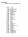
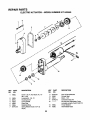
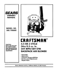
REPAIR PARTS
ELECTRIC
ACTUATOR-
- MODEL
NUMBER
2
8
7
4
s
J
917.242440
/
3
9
I
10
f
\
\
\.
12
\
\
/
14
\
\
\
13
\
\
I
\
\6
KEY
NO.
PART
NO.
1862J
2
3
4
5
6
7
1863J
8331J
1857J
1865J
1864J
677A149
PART
NO.
DESCRIPTION
KEY
NO.
Screw - SI. Fil. Hd. Mach. No. 1032 x 1-5/8
Lockwasher- No. 10
Housing Cover
Cover Gasket
Snap Ring
Retaining Ring
SpringWasher (Use 3 or 4 as
req'd.)
8
9
10
11
12
674A281
1859J
1861J
673A218
13
14
1860J
1858J
22
DESCRIPTION
Pawl & RampWasher
Out put Gear
Motor - 12V
Connector Body Kit
Not Serviced Separately Order
complete actuator Part# 124371X
Thrust Washer
Intermediate Gear
SERVICE NOTES
23
OWNER'S
MANUAL
[RRFT$ AN°
ELECTRIC LIFT
ACTUATOR KIT
for GARDEN TRACTORS
MODEL NO.
917.242440
Each lift kit has its own model number.
This lift kit when mountedto your tractor is not visibly accessible. Therefore, the model plate (included in parts bag) has convenient self-stick
adhesive for placement on tractor. Always mention the model number
when requesting service or repair parts.
IF YOU NEED
REPAIR SERVICE
OR PARTS:
FOR REPAIR SERVICE, CALL
THIS TOLL FREE NUMBER:
All parts listed herein may be ordered from any Sears, Roebuck and Co.
Service Center and most Retail Stores.
WHEN ORDERING REPAIR PARTS, ALWAYS GIVE THE FOLLOWING INFORMATION:
• PRODUCT - ELECTRIC LIFT ACTUATOR KIT
1-800-4-REPAIR
• MODEL NUMBER - 917.242440
(1-800-473-7247)
• PART NUMBER
FOR REPLACEMENT PARTS
INFORMATION AND
ORDERING, CALL THIS
TOLL FREE NUMBER:
1-800-FON-PART
(1-800-366-7278)
• PART DESCRIPTION
Your Sears merchandise has added value when you consider Sears has
service units nationwide staffed with Sears trained technicians.., professional technicians specifically trained to insure that we meet our pledge
to you, we service what we sell.
Sears, Roebuck
142176
11.10.93
and Co., Chicago,
IL 60684 U.S.A.
PRINTED IN U.S.A.