1
SEAl, S
OWNER'S
MANUAL
MODEL NO.
917.250032
®
20 HP IC
ELECTRIC START
6 SPEED TRANSAXLE
GARDEN TRACTOR
Caution:
Read and follow
all Safety Rules
and Instruct,ons
Before Operating
This Equipment
• AssembUy
• Operation
, Customer Responsibilities
• Service and Adjustment
oRepair Parts
Sears,
i
i ,11,,,111,,
Roebuck
, ,,I, ,,,, ,,,N
and Co., Chicago,
i,,
,,,11,,1,1 H,I
II, I,,,,HI,
IL 60684 U.S.A.
A
SAFETY
Practices RULES
for Ride-On
Safe Operation
&
Mowers
IMPORTANT; THIS CUTTING MACHINE IS CAPABLE OFAMPUTATING HANDSAND FEETANDTHROWING
OBJECTS,
FAILURE TO OBSERVE THE FOLLOWING SAFETY INSTRUCTIONS COULD RESULT IN SERIOUS INJURY OR DEATH.
L
GENERAL
•
Read, understand, and follow all instructions in the manual
and on the machine before starting
Only a_low responsible adults, who are familiar with the
instructions, to operate the machine.
Clear the area of objects such as rocks, toys, wire, etc.,
which could be picked up and thrown by the 5lade
Be sure the area is clear of other people before mowing. Stop
machine if anyone enters the area.
Never carry passengers,
Do not mow in reverse unless absolutely necessary. Always
look down and behind before and while backing°
Be aware of the mower discharge direction and do not point
it at anyone. Do not operate the mower without either the
entire grass catcher or the guard in place.
Slow down before turning
Never leave a running machine unattended. Always turn off
blades, set parking brake, stop engine, and remove keys
before dismounting
Turn off blades when not mowing.
Stop engine before removing grass catcher or unclogging
chute.
•
•
•
•
•
•
•
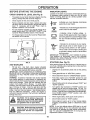
OPERATION
III.
•
Mow only in daylight or good artificial light.
Do not operate the machine while under the influence of
alcohol or drugs..
•
Watch for traffic when operating near or crossing roadways
Use extra care when loading or unloading the machine into
a trailer or truck.
I1o SLOPE
Tragic accidents can occur if the operator is not alert to the
presence of children, Chitdren are often attracted to the machine
and the mowing activity Neverassume that children wilt remain
where you last saw them
-
•
Never carry children. They may fall off and be seriously
injured or interfere with safe machine operation..
Never allow children to operate the machine
,
Use extra care when approaching blind corners,
trees, or other objects that may obscure vision.
IV,
SERVICE
•
Use extra care in handling gasoline and other fuels_ They are
flammable and vapors are explosive.
Use only an approved container.
Never store the machine or fuel container inside where
there is an open flame, such as a water heater.
Never run a machine inside a closed area.
•
Keep nuts and bolts, especially blade attachment bolts tight
and keep equipment n good condition°
Never tamper with safety devices
Check their proper
operation regularly.
Keep machine free ofgrass leaves, orother debris build-up.
Clean el or fuel spillage
Allow machine to cool before
storing..
•
•
•
Avoid starting or stopping on a slope. If tires lose traction,
disengage the blades and proceed slowly straight down the
slope
Stop and inspect the equipment if you strike an object.
Repair, if necessary, before restarting.
Never make adjustments or repairs with the engine running.
Grass catcher components are subject to wear, damage and
deteroration,
which could expose moving parts or altow
objects to be thrown, Frequently check components and
replace with manufacturer's recommended parts, when necessary.
Mower blades are sharp and can cut. Wrap the blade(s) or
wear gloves, and use extra caution when servicing them.
Check brake operation frequently.
Adjust and service as
required.
•
•
•
•
Do not
DO NOT:
in,,
i
i,
!,,,w ,nil1]
wt
............................
tant safety precautions,
It means
CAUTION!!!
BECOME ALERT!!! YOUR
Lookforthissymboltopotntoutimpor.
SAFETY IS INVOLVED,
&
Do not turn on slopes unless necessary, and then, turn slowly
and gradually downhill, if possible.
Do not mow near drop-offs, ditches, or embankments. The
mower could suddenly turn over if a wheel is over the edge
of a cliff or ditch, or if an edge caves in
Do not mow on wet grass. Reduced traction could cause
sliding.
Do not try to stabilize the machine by putting your foot on the
ground..
Do not use grass catcher on steep slopes.
shrubs,
Never remove gas cap or add fuel with the engine
running. Allow engine to cool before refueling. Do not
smoke.
Never refuel the machine indoors
Mow up and down slopes, not across.
Remove obstacles such as rocks, tree limbs, etc.
Watch for holes, ruts, or bumps.
Uneven terrain could
overturn the machine Tall grass can hide obstacles,
Use slow speed, Choose a low gear so that you will not have
to stop or shift while on the slope
Follow the manufacturer's
recommendations
for wheel
weights or counterweights to improve stability.
Use extra care wilh grass catchers or other attachments.
These can change the stability of the machine.
Keep all movement on the slopes slowand gradual
make sudden changes in speed or direct{on.
•
Before and when backing, look behind and down for small
children,
OPERATION
•
•
•
=
DO:
•
Keep children out of the mowing area end under the watchful
care of another responsible adulto
Be alert and turn machine off if children enter the area.
•
Slopes are a major factor related to toss-of-control and tipover
accidents, which can result in severe injury or death. All slopes
require extra caution.. If you cannot back up the slope or if you feel
uneasy on it, do not mow it
•
•
•
CHILDREN
ul,,
CAUTION:
H,l,,
H
,
nl
i
............
ALways disconnect
spark
contact spark plug in order to prevent
plug
wire and
place wire
where
it cannot
accidental
starting
when
setting
up,
transporting,
adjusting
or making
repairs.
v
, ,,n,
I I"MI'
Inl,I
i
hi'
I
II
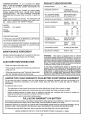
PRODUCT
CONGRATULATIONS
on your purchase of a Sears
tractor. It has been designed, engineered and manufactured to give you the best possible dependability and
performance
SPECIFICATIONS
HORSEPOWER:
20 0
GASOLINE CAPACITY:
3 5 GALLONS
UNLEADED REGULAR
OIL (3 8 PINTS w/Filter)
(35 PINTS w/o FILTER)
SAE 30 (above 32°F)
5W-30 (below 32"F)
Please read and retain this manual, The instructions will
SPARK PLUG (GAP,025 IN ):
CHAMPION RS14YC
enable you to assemble and maintain your tractor properly, Always observe the 'SAFETY RULES.
VALVE CLEARANCE:
INTAKE
005
EXHAUST 013
Should you experience any problem you cannot easily
remedy, please contact your nearest Sears Service
Center/Department.
We nave competent, wetl4rained
technicians and the proper tools to service or repair this
tractor.
MODEL
NUMBER
917.250032
GROUND SPEED:
SERIAL
NUMBER
1st
2rid
3rd
Rev,
IN,
IN.
(MPH):
LO
HI
8
18
14
34
2_4
55
,9
2.1
DATEOF PURCHASE
THE MODELAND SERIALNUMBERS
ON A PLATE UNDER THE SEAT,
WtLL BE FOUND
YOU SHOULD RECORD BOTH SERIALNUMBERAND
DATE OF PURCHASE AND KEEP tN A SAFE PLACE
FOR FUTURE REFERENCE.
MAINTENANCE
NON-DETERGENT
SAE30 (ISO 100)
TIRE PRESSURE:
FRONT:
REAR:
CHARGING
20 AMPS @ 3600 RPM
SYSTEM:
BLADE BOLT TORQUE:
AGREEMENT
A Sears maintenance agreement is available on this product. Contact your nearest Sears store for details,
CUSTOMER
TRANSAXLE OIL
(4 QUARTS CAPACITY)
Read and observe the safety rules.
•
Follow a regular schedule in maintaining, caring for and
using your unit.
•
Follow the instructions under "Customer Responsibilities" and "Storage" sections of this manual,
LIMITED TWO YEAR WARRANTY
30-35 FT LBS
WARNING',
This tractor is equipped with an internal
combustion engine and should not be used on or near any
unimproved forest-covered, brush-covered or grass-covered land unless the engine's exhaust system is equipped
with a spark arrester meeting applicable local or state laws
(if any), If a spark arrester is used, it should be maintained
in effective working order by the operator
RESPONSIBILITIES
•
t4 PSI
10 PSt
In the state of California the above is required by law
(_Section 4442 of the California Public Resources Code)°
Other states may have similar laws. Federal laws apply on
federal tands, A spark arrester for the muffler is available
through your nearest Sears Authorized Service Center/
Department (See REPAIR PAR-IS section of this manual).
ON ELECTRIC
START RIDING EQUIPMENT
For two years from date of purchase, when this riding equipment is maintained, lubricated, and tuned up according to the
operating and maintenance instructions in the owner's manual, Sears will repair free of charge any defect in material or
workmanshiF
This Warranty does not cover:
•
•
Tire replacement or repair caused by punctures from outside objects (such as nails, thorns, stumps, or glass).
Expendable items which become worn during normal use, such as blades, spark plug, air cleaners and belts,
Repairs necessary because of operator abuse or negligence, including bent crankshafts and the failure to maintain the
equipme.ntaccording to the instructions contained in the owner's manual.
•
Riding equipment used for commercial or rental purposes,
FULL 90 DAY WARRANTY
ON BATTERY
For 90 days from date of purchase, if any battery included with this riding equipment proves defective in material or workmanship
and our testing determines the battery will not hold a charge, Sears wilt replace the battery at no charge,,
WARRANTY SERVICE IS AVAILABLE BY CONTACTING THE NEAREST SEARS SERVICE CENTER/DEPARTMENT IN THE
UNITED STATES. THIS WARRANTY APPLIES ONLY WHILE THIS PRODLJCT1SIN USE IN THE UNITED STATES,,
This Warranty gives you specific legal rights, and you may also have other rights which vary from state to state,
SEARS, ROEBUCK AND CO., DI731CR-W SEARS TOWER, CHICAGO, IL 60684
.......
urn,
3
TABLE
OF CONTENTS
SAFE'rf RULES ............................................................
2
OPERATION ...........................................................
10-12
PRODUCT SPECIFICATIONS ....................................... 3
MAINTENANCE SCHEDULE ...................................... 13
SERVICE AND ADJUSTMENTS ............................ 17-20
CU STOMER R ESPONSIBILtTtES ..................... 3, 13-16
WARRANTY ...................................................................
3
STORAGE ,.. ................................................................
21
TABLE OF CONTENTS .................................................
4
TROU BLESHOOTING ............................................
22-23
INDEX .............................................................................
4
REPAIR PARTS - TRACTOR ................................. 25-39
TRACTOR ACCESSORIES ........................................... 5
REPAIR PARTS - ENGINE ..................................... 40.49
PARTS ORDERING/SERVICE ................... BACK PAGE
ASSEMBLY ................................................................
7-9
INDEX
A
E
Accessories
Adjustments;
Attachment Lift Spring ....................19
Brake ........................................................
17
Carburetor ...............................................
20
Clutch .................................................17
Throttle Control Cable .........................
20
Toe-In ...................................................
18
Air Filter, Engtne
16
Air Screen, Engine
16
Assembly ....................................................
7-9
P
Electrical:
Parking Brake .................................... 10-11
Interlocks and Relays .................. lg
Parts Bag ..........................................................
6
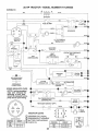
Schematic .........................................
25
Parts, Replacement/Repair .............
25-49
Widng Diagram
26
Product Specifications ................................3
Engine:
R
Air Filter .......................................... 16
Air Filter Foam Pre-Oleaner ..........16
Repair Parts ........................................25-49
Air Screen .............................................
16
S
Cooling Fins, Engine
16
Safety Rulee ............................................. 2
Oil Change ........................................t 5
Seat ........................................................... 8
Oil Level
12,15
Service and Adjustments ................ 17-20
B
OilType ................................................
15
Attachment Lift Spring ................. 19
Battery:
Preparation .......................................
...12
Carburetor ....................................... 20
Charging ..............................................8
Repair Parts ............................
40.49
Clutch ............................................... 17
Cleaning ..................................................
14
Starting .....................................................
12
Fuse
Installation ...............................................
9
Storage ...............................................21
Hood Removal/Installation ...........20
F
Levels .................................................
8,14
Motion Drive Belt
Preparation ........................................ 8
Filter:
RemovallReplaeement
.............18
Starting with Weak Battery .............19
Air Filter ...............................................
16
Tire Care ..................................... 8,19
Air Filter Foam Pre-Cleaner ......... 16
Storage .................................................
21
Toe-In ............................................. 18
Terminals .........................................
14
Fuel ................................................. 16
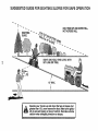
Slope Guide Sheet .................................5t
Belt:
O11
16
Spark Plugs ............................................. !6
Motion Drive
Fuel:
Speclfications ................................................
3
Removal/Replacement
............ 18
Type
12
Starting the Engine ................................. t2
Brake Adjustment ........................................
1'7
Storage ...............................................21
Steering Wheel .................................. 7,18
C
Fuse ...............................................................
1g
Stopping the Tractor .............................. 11
H
Carburetor Adjustment ...........................20
Storage ................................................... 21
Clutch Adjustment
Hood Removal/Installation ......................20
T
Controls, Tractor .................................... 10
I
Throttle Controt Cable
Customer Responsibititles ...............13-16
Indicator Lights ..................................... 12
Adjustment ........................................2C
Engine:
L
Tires
........................................................ 8,1£
Air Filter .........................................16
Lubrication
Chart
.....................................13
Air Filter Foam Pro-Cleaner .... 16
Trouble Shooting Chaff ....................22-2,_
................
.............................
.......
5
...............................
......
..............................
....................
.............................................
...............................
.....................................................
I
9
.........................................................
........................................................
.....................................
l
7
M
Air Screen, Engine .........................
16
Maintenance Schedule .......................... 13
Battery ..........................................14
Muffler ...................................................... 16
CoolingFins,Engine .....................
16
Spark Arrestor ...............................3,30
Engine Oil
15
O
Fuel Filter
16
Oil:
Spark Plugs ................................ 16
Tractor:
Cold Weather Conditions ....... 12,15
Filter .......................................................
16
Lubrication Chart ...........................
13
Maintenance Schedule ..............13
Engine ............................................. 15
Storage ............................................. 21
Tire Care
"Transaxle ...................................... 14
Operation
Options:
Accessories ........................................5
Spark Arrester
3,30
.........................................
........................................
.......................................
8,19
...........................................
1
................................
4
0--t
2
Transaxle:
Oil Level .............................................1_
Repair Parts .................................36-3";
W
Warranty
..................................................
.....
Wiring Diagram .............................................
2_
Wiring Schematic ........................................
2._
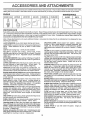
ACOESSORBES AN
,,t
i
J
i
ATTACHMENTS
i
These accessories and attachments were available when the tractor was purchased They are also available at most Sears retail outlets,
catalog and service centers.. Most Sears stores can order these items for you when you provide the model number of your tractor
ENGINE
SPARK PLUG
MAINTENANCE
MUFFLER
AIR FILTER
GAS CAN
ENGINE OIL
STABILIZER
BLADES
BELTS
PERFORMANCE
Sears offers a wide variety of attachments that fit your tractor,
you_ This list was current at the time of publication; however,
may be made in these attachments, or some may no longer
accessories and attachments
that are available for your
Most of these attachments
attaching and detaching
Many of these are listed below with brief explanations of how they can help
it may change in future years - more attachments may be added, changes
be availabte or fit your model. Contact your nearest Sears store for the
tractor.
do not require additiona_ hitches or conversion kits (those that do are indicated) and are designed for easy
TRACTOR COVER protects tractor from weather
Made of
Evolution 3 fabric (water-repellent, extremely breathable, light
weight, soft, non-abrasive, pliable in alt temperatures, durable,
stain]tear/puncture resistant, will not shrink or stretch). (Catalog
only)
LAWN SWEEPERS iet you collect grass cIippings and leaves
LAWN VACS for powerful co]fection of heavy grass clippings and
leaves, Wand attachment to pick up debris in hard-to.reach
places,
CARTS make hauling easy, Variety of sizes available,
ROLLER for smoother lawn surface.
36-inch wide, 18-inch
dlameter water-tight drum holds up to 390 lbs. of weight,. Rounded
edges prevent harm to turf, Adjustable scraper automatically
cleans drum.
TILLER has 8 hp engine to prepare seed beds, cultivate, and
compost garden residue_ Chaimdrive transmission. Six 11-inch
diameter one piece heat-treated steel tines Tills 30-inch path
(Requires sleeve hitch.)
TILLER has 5 hp engine and 36-inch swath to prepare seed beds,
cultivate, and compost garden residue. Tiller has its own built-in
lift and depth control system and does NOT require a sleeve hitch
Fits any lawn, yard, or garden tractor.. Simply hook up to the
tractor drawbar and go!
DOZER BLADE removes snow; grades dirt, sand and gravel 48
inches wide, 17 inches high, clears 44-inch path when angled.
Master lift control lever for operator ease.. Spring trip for snow
removal on uneven pavement; built-in float for b}ade to fot_ow
ground contour. Reversible, replaceable scraper bar. (Use with
tire chains, wheel weights or rear drawbar weight.)
SPREADER/SEEDERS
make seeding, fertilizing, and weed killing easy, Broadcast spreaders are also usefut for granular deicers and sand,
CORING AERATOR takes small plugs out of soil to allow moisture and nutrients to reach grass roots. 36-inch swath, 24
hardened steel coring tips. 150 Ib, capacity weight tray_
AERATOR promotes deep root growth for a healthy lawn, Tapered 2 54nch steel spikes mounted on 10-inch diameter discs
puncture holes in soil at close intervals to _et moisture soak in,
MULCH RAKE/DETHATCHER
loosens soil and flips thatch and
matted leaves to lawn surface for easy pickup. Twenty spring tine
teeth, Useful to prepare bare areas for seeding, Available for front
or rear mounting.
SPRAYERS use 12-volt DC electric motor that connects to the
tractor battery or other 12-volt source.
Includes booms for
automatic spraying when pulling, and hand held wand for spot
spraying, Wand has adjustable spray pattern, For applying
herbicides, insecticides, fungicides, and liquid fertilizers°
FRONT END LOADER system includes double wide rear tires,
rear weight box, and hydraulically operated 5.26 cu..ft, bucket
(Catatog onlyo)
R EAR BLADE is42 inches wide and operated from driver's seat.
Reversible steel blade can be angled at 30 degrees for grading
Reverses for snow plowing. (Requires sleeve hitch.)
SLEEVE CULTIVATOR is 43 inches wide° Prepares ground for
seeding, helps weed control. Steel frame holds 5 adjustable
sweeps., Adjusts vertically, horizontally. (Requires sleeve hitch.)
Optional accessory for cultivator: steel furrow opener for wider
openings for potatoes, corn, and other deep-seeded crops
PLOW turns soil 6 inches deep, cuts lO-inch furrow. Crank
adjustment controls depth, 3-position yoke sets width. Heavy
steel landslide for straight furrowing.. (Requires sleeve hitch.)
DISC HARROW has 2 gangs of 4 steel blades that angle from 10
to 20 degrees, 40 inches wide_ Can hook 2 units in tandem
(Requires sleeve hitch.)
SNOWTHROWER has 40-inch swath,, Drum-type auger handles
powdery and weUheavy snow. Mounts easily with simple pin
arrangement
Discharge chute adjusts from tractor seat, 6-inch
diameter spout discharges snow 10 to 50 feet. Lift controlled at
tractor seat. (Use with chains, wheel weights, or rear drawbar
weight.)
TIRE CHAINS are heavy duty; closely spaced extra4arge cross
links give smooth ride, outstanding traction,,
WHEEL WEIGHTS for rear wheels provide needed traction for
snow removal or dozing heavy material&
(55 tbs each )
TRACTOR CAB has heavy duty vinyl fabric over tubular steel
frame, ADS plastic top; clear plastlc windshield offers 360 degree
visibility,, Hinged metal doors with catch, Keeps operator warm
and dry,. Remove vinyl and windshields for use as sun protector
in summer
(Catalog only)
Optional accessories
for tractor cab: tinted/tempered solid
safety glass windshield with hand operated wiper; 12-volt amber
caution light for mounting on cab top, (Catalog only,,)
WEIGHT BRACKET for drawbar for snow removal applicationsCan be mounted on front of tractor for plowing applications. Uses
(1) 55 lb,. weight_
SLEEVE HITCH for use with master lift system,,
couples/uncouples
5
Single pin
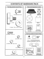
Parts Bag contents
Parts packed separately in carton
shown full size
i
,,
i=
i,i
,,i,,,
i
,,i
....,,,,,,,,,
, ,,i
O
I
Seat
(t) Shoutder Bolt 5/16-1B
Battery acid
(1) Knob
Steering Wheel
Battery
I
(l) Washer
17/32 x I-3/16 x 12 Gauge
Parts Bag
Owner's
Manual
Parts bag contents not shown full size
(2) Hex Bolts 1/4-20 x 3/4
@
! ____
(2) Keys
Wheel
Steering
Insert
__
(2) Hex Nuts 1/4-20
(2) Battery Carriage
(2) Washers
Bolts 1/4-20 x 7-1/2
9/32 x 5/8 x 16 Ga,,
Terminal Guard
(2) Lock Washers
,N,,,,,,
,,11=1
t/4
.........
/
,
t
(2) Wing Nuts 1/4-20
15 = Slope Sheet
f
Battery Caps
and Instructions
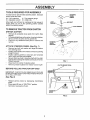
ASSEMBLY
TOOLS
REQUIRED
FOR ASSEMBLY
A socket wrench set wilt make assembly easier. Standard
wrench sizes are listed
(2) 7/16" wrenches
(1) Adjustable wrench
_
STEERING
_,....- WHEEL
INSERT
(t) Tire pressure gauge
(t) Utility knife
LOCK
WASHER
When right and left hand is mentioned in this manual, it
means when you are in the operating position (seated
behind the steering wheel).
,_ HEX BOLT
PLAT WASHER
TO REMOVE TRACTOR FROM CARTON
UNPACK
*
.
.
Remove all accessible loose parts from carton (See
page 6)
Cut along dotted lines on the carton, from top to bottom,
ail four corners of carton and lay panels fiat,
Check for any additional loose parts or cartons and
remove
ATTACH
•
•
*
•
,
CARTON
STEERING
WHEEL
STEERING
(See Fig. 1)
Remove hex bolt, lock washer and large fiat washer
from steering shaft,
Position front wheels of the tractor so they are pointing
straight forward
Position steering wheel so cross bars are horizontal
(left to right) andslide onto adapter,
Secure steering wheel to steering shaft with hex bolt
lock washer and large flat washer previously removed
Tighten securely
Snap insert into center of steering wheel.
Remove protective plastic from tractor hood and grill,
BEFORE
ROLLING
TRACTOR
SHAFT
FIG. 1
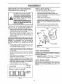
CLUTCH/BRAKE PEDAL
OFF SKID
IMPORTANT: CHECK FOR AND REMOVE ANY STAPLES
iN SKID THAT MAY PUNCTURE TIRES WHERE TRACTOR
iS TO ROLL OFF SKID
(See Fig. 2)
,
,
,
Release parking brake by depressing clutch/brake
pedal.
Place gearshift lever in "NEUTRAL" position.
Roll tractor backwards off skid.
PARKING
BRAKE
LEVER
FIG. 2
7
HOW TO SET UP YOUR TRACTOR
INSTALL SEAT (See Fig. 4)
PREPARE
Adjust seat before tightening adjustment knob,,
BATTERY
(See Fig, 3)
•
Remove cardboard packing on seat pan.
CAUTION: Wear eye and face shield.
•
Place seat on pan and assemble shoulder bolt,
Wash hands or clothing immediately if
accidentallyin
contact with battery acid.
•
Assembte adjustment knob, Iockwasher and flat washer
loosely Do not tighten_
•
Tighten shoulder bolt securely.
.
Lower seat into operating position and sit on seat.
•
Slide seat until a comfortable position is reached which
allows you to press clutch/brake pedal aU the way
down.
•
Get off seat without moving its adjusted position°
•
Raise seat and tighten adjustment knob securely.
,ll i
H
",,
I
I IllL
H ..............
battery
Do
not acid
smoke.
are explosive.
Fumes from charged
Read the instructions included with the
batteryvent caps. Alwaysweargloves,
clothing and goggles to protect your
hands, skin and eyes.
Your tractor has a battery charging system which is sufficient for normal use. However, periodic charging of the
battery with an automotive charger wil! extend its life,
•
See instructions packed with vent caps in parts bag.
•
Fitl battery with acid Fill each cell until it reaches the
bottom of the vent wells Do not overfill_
•
Allow battery to stand and settle for at least thirty
minutes_ After standing, check the level of acid. If
below the vent wells, add more acid untii the correct
level is reached
SEAT
SEAT PAN
SHOULDER
BOLT
While battery is standing (after adding acid) and later, while
battery is being charged, continue with assembly of tractor.
IMPORTANT:
TO MAXIMIZE THE LIFE OF YOUR
BATTERY, IT tS NECESSARY THAT THE BATTERY BE
CHARGED BEFORE USE.
FAILURE TO CHARGE
BATTERY CAN RESULT IN A SHORTENED BATTERY
LiFE
FLAT WASHER
•
Charge battery at a rate of 6 amperes for 1 hour. Use
a 12 vott battery charger. Observe all safety precautions required for battery charging
•
Check the acid level after the battery is charged, If the
acid has fallen below the correct level, add distilled or
iron free water
•
Install the vent caps to cover the vent wells, Wash the
top of the battery with water to remove any acid, then
w_pe dry.
•
Check battery case for leakage to make sure that no
damage has occurred in handling.
•
•
Dispose of excess battery acid. Neutralize acid for
disposal by adding it to four inches of water in a five
gallon plastic container, Stir with a wooden or plastic
paddle while adding baking soda until the addition of
more soda causes no more foaming,
CHECK BRAKE SYSTEM
•
ADJUSTMENT
KNOB
FIG. 4
CHECK
The tires on your tractor were overinflated at the factory fo
shipping purposes, Correct tire pressure is important fo
best cutting performance_
Reduce tire pressure to PSi shown in "PRODUC"
SPECIFICATIONS" on page 3 of this manual,
After you learn how to operate your tractor, check to set
that the brake is properly adjusted, See 'TO ADJUS
BRAKE in the Service and Adjustments section of thi
manual.
Fellow instructions on how to install battery
CUT AWAY VIEW
TIRE PRESSURE
VENT CAP
VENT WELL
BATTERY
CELL ACID
LEVEL
FIG. 3
8
TERMINAL
A
CAUTION: Do not short battery terminals. Before installing battery, remove
metal bracelets, wristwatch bands,
rings, etc.
Positive terminal must be connected
first to prevent sparking from accidental grounding.
•
Raise hood.
•
Make sure d rain tube is fastened to drain hole in battery
tray and battery tray is positioned in hole of battery
support,
BATTERY BOLT
CAPS
BATTERY TRAY
FiG. 6
•
Place battery in plastic tray, battery terminals to front of
tractor.
•
First connect RED battery cable to positive (+) battery
terminal with hex bolt, fiat washer, lock washer and hex
nut as shown. Tighten securely,
•
Connect BLACK grounding cable to negative (-) battery
terminal with remaining hex bolt, flat washer, lock washer
and hex nut, Tighten securely,
•
Slide the two battery bolts through the terminal guard
and start the wing nuts onto the threads°
•
Position terminal guard over the battery as shown, lower
bolts into key holes and slide square shatts of bolts into
slots of key holes.
J'
All assembly instructions have been completed
,/
No remaining loose parts in carton
,
Tighten wing nuts by hand making sure battery bolts
remain in slots of the key holes in the battery support.
,/
Battery is properly prepared and charged,
hour at 6 amps),
,
Be sure terminal access doors are closed.
€" Seat is adjusted comfortably and tightened securely.
,/'CHECKLIST
BEFORE YOU OPERATE AND ENJOY YOUR NEW
TRACTOR, WE WISH TO ASSURE THAT YOU RECEIVE
THE BESTPERFORMANCEAND
SATISFACTION FROM
THIS QUALITY PRODUCT.
PLEASE REVIEW THE FOLLOWING CHECKLIST.
Use terminal access doors for:
,
Inspection for secure connections (to tighten hardware).
,
Inspection for corrosion_
•
Testing battery.
•
Jumping (if required).
•
Periodic charging.
(Minimum 1
€"
Ail tires are properly inflated. (For shipping purposes,
the tires were over-inflated at the factory)r
€"
Be sure mower deck is properly leveled side-to-side/
front°to-rear for best cutting results. (Tires must be
properly inflated for leveling).
v"
Check mower and drive belts. Be sure they are routed
properly around pulleys and inside all belt keepers,
€"
Check wiring. See that all connections are still secure
and wires are properly clamped.
WHILE LEARNING HOW TO USE YOUR TRACTOR, PAY
EXTRA ATTENTION TO THE FOLLOWING IMPORTANT
ITEMS:
FLAT
WASHER
(NEGATIVE)
BLACKCABLE
"';,._r_.
v"
Engine oil is at proper level
#"
Fuel tank is filled with fresh, clean, regular unleaded
gasoline.
Become familiar with all controls-their location and
function. Operate them before you start the engine.
,/
f%
DRAIN TUBE
FLAT WASHER
,/
FIG. 5
9
Be sure brake system is in safe operating condition.
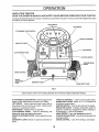
KNOW YOUR TRACTOR
READ THIS OWNER'S MANUAL
AND SAFETY
RULES
BEFORE
OPERATING
YOUR TRACTOR.
Compare the illustrations with your tractor to familiarize yourself with the location of various controls and adjustmentSr Save
this manual for future reference,
UGHT SWITCH
LIFT SWITCH
ATTACHMENT
CLUTCH SWITCH
,THROTTLE
INDICATOR
CONTROL
LIGHTS
HOUR METER
CLUTCH/BRAKE
PEDAL
IGNITION SWITCH
PARKING
HEIGHT
ADJUSTMENT
KNOB
GEARSHIFT
BRAKE
LEVER
RANGE SHIFT LEVER
FIG. 7
Sears tractors conform to the safety standards of the American National Standards Institute,
ATTACHMENT CLUTCH SWITCH - Used to engage mower
blades or other attachments mounted to your tractor_
LIFT SWITCH _ Used to raise and lower mower deck or
other attachments mounted to your tractor, ignition switch
must be on to operate this switch.
HOUR METER - indicates hours of operation.
CLUTCH/BRAKE
PEDAL - Used for declutching and
braking the tractor and starting the engine,
HEIGHTADJUSTMENT
KNOB- Used to adjust the mower
heighL
GEARSHIFT LEVER: Selects the speed and direction of
tractor,
THROTTLE CONTROLUsed to control engine speed.
RANGE SHIFT LEVER - Allows "Hi" or 'LO" speed for all
forward and reverse gears.
IGNITION SWITCH - Used to start and stop the engine.
INDICATOR LIGHTS - Indicates clutch/brake pedal engagement, attachment engagement, battery charging (+)
or discharging (-), and low oil pressure,
LIGHT SWITCH - Turns the headlights on and off,
PARKING BRAKE LEVER - Locks clutch!brake pedal into
the brake position°
CHOKE CONTROL - Used when starting a cold engine°
10
.....
....._
. .........
.. =.....=...,,
........ =,
..... ,
OPERATION
The operation of any tractor can result in foreign objects thrown into the eyes, which can result
in severe eye damage. Always wear safety glasses or eye shields before starting your tractor
and while moving. We recommend wide vision safety mask for over the spectacles or standard
safety glasses,
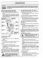
HOW TO USE; YOUR TRACTOR
TO USE CHOKE
TO SET PARKBNG
Use choke control whenever you are starting a cold engine.
Do not use to start a warm engine.
BRAKE
(See Fig. 8)
•
Depress clutch/brake pedal into full "BRAKE" position
and hold.
•
Place parking brake lever in "ENGAGED" position and
release pressure from clutch/brake pedal. Pedal should
remain in "BRAKE" position° Make sure parking brake
will hold tractor secure.
CLUTCH/BRAKE
PEDAL "BRAKE"
ATTACHMENT
CLUTCH SWITCH
-
CONTROL
To engage choke control, pull knob out
knob in to disengage_
TO USE THROTTLE
/
CONTROL
CONTROL
Slowly push
(See Fig• 8)
Always operate engine at full throttle.
.
Operating engine at less than full throttle reduces the
battery charging rate and the engine cooling air flow.
•
Full throttle offers the best mower performance.
TO MOVE FORWARD
POSITIO
(See Fig. 8)
AND BACKWARD
(See Fig. 8)
The direction and speed of movement is controlled by the
gearshift lever.
GEARSHIFT
\
t
KEY
*
Start tractor with clutch/brake pedal depressed and
gearshift lever in "NEUTRAL" position°
•
Move gearshift and range shift levers to desired position,
•
Slowly release clutch/brake pedal to start movement_
IMPORTANT: BRING TRACTOR TO A COMPLETE STOP
BEFORE SHIFTING OR CHANGING GEARS. FAILURE
TO DO SO WILL SHORTEN THE USEFUL LIFE OF YOUR
TRANSAXLE.
TO OPERATE
FIG. 8
STOPPING (See Fig. 8)
MOWER BLADES •
Move attachment
position_
GROUND DRIVE-
i
Depress clutch/brake pedal into full "BRAKE" position.
•
Move gearshift lever to "NEUTRAL" position.
Move throttle control to 'SLOW"position.
•
Turn ignition key to "OFF" position and remove key.
Always remove key when leaving vehicle to prevent
unauthorized use.
•
Never use choke to stop engine.
NOTE; Under certain conditions when tractor is standing
idle with engine running, hot engine exhaust gasses may
sause "browning" of grass, To eliminate this possibility,
always stop engine when stopping tractor on grass covered
areas°.
l&
pletely, as described above, before leavIng
the operator's
to empty
CAUTION;
Always posttion;
stop tractor
comgrass catcher, etc.
hills with slopes greater than 15 ° and
CAUTION;
not drive
up or down
do not drive Do
across
any slope.
Choose the slowest speed before starting up or down
hiIIs°
•
Avoid stopping or changing speed on hills.
•
If slowing is necessary, move throttle control to slower
position_
•
If stopping is absolutely necessary, push clutch/brake
pedal quickly to brake position and engage parking
brake.
•
•
Move gearshift lever to "NEUTRAL" position,,
To restart movement, move gearshift lever to 1st gear
and range shift lever to "LO" position. Be sure you have
allowed room for tractor to roll slightly as you restart
movement_
•
Slowly release parking brake and clutch/brake
•
Make all turns slowly,
ENGINE •
........................
I
•
clutch switch to "DISENGAGED"
.
ON HILLS
pedal,
TO TRANSPORT
-
Raise attachment lift control to highest position,
-
When pushing or towing your tractor, be su re gearshift
lever is in "NEUTRAL" position,
11 *
Do not push tractor at more than five (5) MPHo
OPERATION
]BEFORE STARTING
CHECK
ENGINE
THE ENGUNE
OiL LEVEL
The engine in your tractor has been shipped, from the
factory, already filled with summer weight oil.
•
Check engine oil with unit on level ground.
°
Remove dipstick and wipe clean, replace and screw
cap tight, wait for a few seconds, remove and read oil
level. If necessary, add oil until "FULL" mark on
dipstick is reached. Do not overfill.
DEPRESS
FOOT
•Indicates you must depress clutch/brake
pedal fully to start tractor.
PEDAL
• Indicates you must disengage attachment
clutch control to start tractor,
For cold weather operation you should change oil for
easier starting (see "OIL VISCOSITY CHART' in the
Customer Responsibilities section of this manual)_
.
LIGHTS
Located on the dash of your tractor, these lights alert you
to necessary steps required to start your unit or, while
tractor is running, alerts you to a serious problem which
requires immediate attention
(See Fig. 9)
°
.
INDICATOR
DIBENGAGE
A'I_ACHM_f
To change engine oil, see the Customer Responsibilities section in this manual
BATTERY
DISCHARGtNG
CHECK
OIL
ENGINE OIL
FILLER CAP
& DIPSTICK
• Indicates a drop in battery voltage, Increase throttle speed and/or check battery
and wiring (See the Customer Responsibilities and Trouble Shooting sections in this
manual).
- Indicates low oit pressure in your engine
Light should come on when engine is not
running and key switch is in "ON" position
This is a test to be sure light is working and
a reminder to always check oil level before
starting engine
IF CHECK OIL LIGHT COMES ON WHILE
IMPORTANT:
THE ENGINE
IS RUNNING,
SHUT
OFF ENGINE
IMMEDIATELY
AND CHECK FOR CAUSE OR SERIOUS
ENGINE DAMAGE WILL OCCUR.
STARTING
FIG. 9
ADD GASOLINE
•
Fill fuel tank
Use fresh, clean, regular unleaded
gasoiine (Useof leaded gasolinewilIincreasecarbon
and lead oxide deposits and reduce valve life).
IMPORTANT= WHEN OPERATING IN TEMPERATURES
BELOW 32°F(0°C), USE FRESH, CLEAN WINTER GRADE
GASOLINE TO HELP INSURE GOOD COLD WEATHER
STARTING
WARNING:
Experience indicates that alcohol blended
fuels (called gasohol or using ethanol or methanol) can
attract moisture which leads to separation and formation of
acids during storage
Acidic gas can damage the fuel
system of an engine while in storage
To avoid engine
problems, the fuel system should be emptied before storage of 30 days or longer
Drain the gas tank, start the
engine and let it run until the fuel lines and carburetor are
empty, Use fresh fuel next season See Storage Instructions for additional information.
Never use engine or
carburetor cleaner products in the fuel tank or permanent
damage may occur
filler neck. Do not overfill. Wipe offany
CAUTION:
bottom
of gas
spilled
oil or Fill
fuel.to Do
not store,
spilltank
or
use gasoline near an open flame.
i
,HH
H
InlHH
I'"!_
HH
I'
(See Fig.13)
When starting engine for the first time or if engine has run
out of fuel, itwill take extra cranking time to move fuel from
the tank to the engine.
I
I 'IUU,U
-
Depress the clutch/brake
brake
pedal and set the parking
.
Place gearshift lever in "NEUTRAL" position
.
Move attachment clutch to "DISENGAGED"
.
Pull choke control out to "CHOKE"position
for cold
engine start For warm eng{ne start do not use choke
control
•
Move throttle control to midway between "FAST" and
"SLOW" positions
.
Turn ignition key clockwise to "START" position and
release key as soon as engine starts. Do not run
starter continuously for more than fifteen seconds per
minute. If engine does not start after several attempts,
move throttle control to "FAST" position, wait a few
minutes and try again
•
When engine starts, slowly push choke control in
•
Move throttle control to "FAST" position,
•
Allow engine to warm up for a few minutes before
en_aging clutch/brake pedal or attachment clutch
sw_tch
position.
NOTE; If at a high altitude (above 3000 feet) or in cold
temperatures (below 32 ° F), the carburetor fuel mixture
may need to be adjusted for best engine performance.
See "TO ADJUST CARBURETOR
in the Service and
Adjustments section of this manual,
instals mower or remove front mower
CAUTION:
the tractor,
suspension Before
bracket driving
and suspension
arms.
12
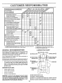
CUSTOMER
RESPONSmB LmES
.............
i u, uu
FILL,.
DATES
AS YOU COMPLETE
[ REGULAR SERVICE
LO_'_
_"_Z_,'_'/_4,,_"
...............
........ check Brake O;erati0n
"_
Check Tire Pressure
_
T
Check for Loose Fasteners .......
$##.
R
SharPen!Replac e Mower Blades
A
Lubrication Chart
'
_'-'_,_-_-"_ __O_,-r_,
_ _
'4_j/" _"__v4_
_
,
,
.........
_
........
! 6_'41
......
_
..Check Battery Level/Recharge
I $f
0
Ctean Battery and Terminals
V'
"Check Transmission
[
_
T
R
,,r, r" r_....
_I:.Hy!L;IU,_/r'_
COoling
.....
..........
.
._#'
V p
.........
Adjust Blade Belt(s) Tension
V'5
Adjust Motion Drive Bert(s) Tension
Ks
V'
€.h.eck Engine Oil Level ......
....
....................................
e,'
Change Engine Oil
Clean Air Filter
NE Clean Air Screen
G
Inspect Muffler/Spark Arrestor
i
Replace Oil Filter (If equipped)
N
clean Engine Cooling Fins
Replace Spark Plug
--_
.
, ,,,,,
v'
,
........
............
................
;:
{
!
Replace Air Filter Paper Cartr.i.d.g.e.
Replace Fuel Filter
1 - Change more often when operating under a heavy toad or tr_ high ambient
2 - Service more oNen when operating in dirtyor dusty conditions
GENERAL
temperatures
Some adjustments
will need to be made
properly maintain your tractor
LUBRICATION
periodically
(_)TIE
(_ SPINDLE ZERK -_
CHART
ROD BALL JOINTS
_
_--
(_) FRONT WHEEL "___:._-::_.¢W
BEARINGZERK
FRONT WHEEL (_)
"_" 1 Z"'t_!:.:?"'_
(_) STEERING .....
Once a year you should replace the spark plug, clean
or replace air filter, and check blades and belts for
wear
A new spark plug and clean air filter assure
proper airfuei mixture and help your engine run better
and last longer.
._
_-;_;
BEARINGZERK
_
_"_.._
1
I I
EACH USE
.
Check engine oil level
•
Check brake operation,
•
•
Check tire pressure.
Check for loose fasteners,
SP|NDLE ZERK (_)
to
AI_ adjustments
in the Service and Adjustments
section of
this manual should be checked at _east once each season.
BEFORE
3 - If equipped with oil filleq change oll every 50 hours
4 • Replace btades more often when mowing tn sandy soil
5 - ff equipped with adjustable system,
RECOMiVIENDATIONS
The warranty on this tractor does not cover items that have
been subjected
to operator
abuse or negligence,
To
receive full value from the warranty,
operator must maintain tractor as instructed
in this manual,
°
tv'
., ,,,, ,,,.....
TRANSAXLE
FLU,D
_J
_ili.
[ "
l
L._J
L_J
_,.
(_) SAE 30 MOTOR OIL API - SG
IMPORTANT: DO NOT OIL OR GREASE THE PIVOT POINTS
WHICH HAVE SPECIAL NYLON BEARINGS. VISCOUS LUBRICANTS WILL ATTRACT DUST AND DIRT THAT WILL SHORTEN
THE LIFE OF THE SELF-LUBRICATfNG BEARINGS, tF YOU
FEEL THEY MUST BE LUBRICATED, USE ONLY A DRY, POWDERED GRAPHITE TYPE LUBRICANT SPARINGLY
(_) GENERAL
PURPOSE GREASE
(_) REFER TO CUSTOMER
RESPONSIBILITIES
(_) SPRAY SILICONE LUBRICANT
13
'*ENGINE"
SECTION
(MOVE BOOTS TO LUBRICATE)
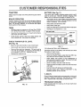
CUSTOM
RESPONS BILITIES
TRACTOR
BATTERY
Always observe safety rules when performing any maintenance.
Your tractor has a battery charging system which is sufficient for normal use. However, periodic charging of the
battery with an automotive charger will extend it's life.
BRAKE
.
Acid solution levee in each battery cel! should be even
with bottoms of vent wells. Add only distilled or ironfree
water if necessary, Do not overfill.
•
•
•
Keep battery and terminals clean.
Keep battery botts tight.
Keep vent caps tight and small vent holes in caps open.
•
Recharge at 6 amperes for '1 hour.
OPERATION
If tractor requires more than six (6)feet stopping distance
at high speed in highest gear, then brake must be adjusted.
(See TO ADJUST BRAKE" in the Service and Adjustments section of this manual).
TIRES
•
Maintain proper air pressure in all tires (See "PRODUCT SPECIFICATIONS'
on page 3 of this manual).
•
Keep tires free of gasoline, oil, or insect control chemicals which can harm rubber,.
•
(See Fig. 11)
CUT AWAY VIEW
_
_
.....
j
VENT CAP
VENT
"
Avoid stumps, stones, deep ruts, sharp objects and
other hazards that may cause tire damage.
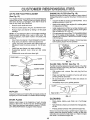
BATTERY
CHECK
TRANSAXLE
OIL
LEVEL
LEVEL
(See Fig.
10)
•
Block up rear axle securely or use a tractor jack,
•
Remove left rear wheel by removing hub bolts.
•
Remove filler plug from transaxle
Oil level must be
even with plug threads, if necessary, fill with SAE 30
non-detergent oil API-SG. Replace filler plug,
Reassemble wheel to hub,
•
FIG. 11
TO CLEAN BATTERY AND TERMINALS
Corrosion and dirt on the battery and terminals can cause
the battery to "leak" power.
* Remove terminal guard.
•
Disconnect BLACK battery cable first then RED bat..
tery cable and remove battery from tractor.
,
Wash battery with solution of four tablespoons of
baking soda to one pal!on of water. Be careful notto get
the soda solution into the cells.
TRANSAXLE
FILLER PLUG
O
-
•
,
O
•
,
Rinse the battery with plain water and dry.
Clean terminals and battery cable ends with wire brush
until bright.
Coat terminals with grease or petroleum jelly.
Reinstall battery (See "iNSTALL BATTERY" in the
Assembly section of this manual).
V- BELTS
Check V-Belts for deterioration and wear after 100 hours of
operation. Replace if necessary. The belts are not adjustableo Replace belts if they begin to slip from wear.
TRANSAXLE
COOLING
Keep transaxle free from build-up of dirt and chaff which
can restrict cooling.
FIG. 10
14
PO
LRTHES
,in
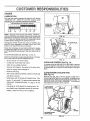
ENGINE
LUBRICATION
On}y use high quality detergent oil rated with API service
classification SG, Select the oil's SAE viscosity grade
according to your expected operating temperature.
RECOMMENDED
SAE VISCOSITY GRADES
ENGINE OIL
FILLER
& DIPSTICK
_F -20 °
0°
32 °
609
80 °
100°
_C -29 _
q8 °
0°
16 _
27 _
38"
NOTE: Although multi-viscosity oils (5W30, 10W30 etc,
improve starting in cold weather, these multi-viscosity oils
will result in increased oil consumption when used above
32°F. Checkyour engine oil levelmorefrequentlyto
avoid
possible engine damage from running low on oil
FIG. 12
OIL DRAIN PLUG
Change the oil after the first two hours of operation and
every 50 hours thereafter or at least once a year if the
tractor is not used for 50 hours in one year.
Check the crankcase oil level before starting the engine
and after each eight (5) hours of continuous use. Tighten
oil fill cap/dipstick securely each time you check the oil
level.
TO CHANGE ENGINE OiL (See Figs. 12 and 13)
Determine temperature range expected before oil change,
All oil must meet API service classification SG.
'
Be sure tractor is on level surface.
•
•
•
FIG, 13
CLEAN
Oil will drain more freely when warm.
Catch oil in a suitable container.
Remove oil fill dipstick.
enter the engine when changing oil..
Remove drain plug.
•
After oil has drained completely, replace oil drain plug
CLEAN ENGINE
(See Fig. 14)
and tighten securely.
•
Do not overfill. For approximate capacity see
"PRODUCT
manual.
•
SPECIFICATIONS"
on page 3 of this
Use gauge on oil fill dipstick for checking level. Be
CLEAN ENGINE
COOUNG FINS
sure dipstick cap is tightened securely for accurate
reading.
COOLING
FINS
Remove any dust, dirt or oi! from engine cooling fins to
prevent engine damage from overheating° Air guide covers
must be removed. Remove side panels and hood (See TO
REMOVE HOOD AND GRILL ASSEMBLY" in the Service
and Adjustments section of this manual.
Refill engine with oil through oil fill dipstick tube. Pour
slowly.
(See Fig. 14)
Air screen must be kept free of dirt and chaff to prevent
engine damage from overheating. Clean with a wire brush
or compressed air to remove dirt and stubborn dried gum
fibers.
Be careful not to allow dirt to
•
AIR SCREEN
HEAT
SHIELD
Keep oil at "FULL" line on dipstick
AIR
SCREEN
AIR GUIDE COVER
(BOTH ,SIDES)
FIG, 14
15
......
1... i.ll-iT,,
........................
. ...i.1..
CUSTOMER
_:_
.i....li
AIR FILTER
FOAM
i.,,,,t
1.1.=
. .i..._ ....
i
RESPONSiBiLiTIES
. .,i,,
..................
,,i.,
PRE-CLEANER
ENGINE
..
'"!ll' ",1
OIL FILTER (See
Fig. 16)
Replace the engine oil filter every season or every other oil
change if the tractor is used for more than 100 hours in one
year.
(See Fig. 15)
Your engine will not run properly and may be damaged by
using a dirty air filter. Clean the foam pre-cleaner element
after every 25 hours of operation, more often if tractor is
used in very dusty, dirty conditions,
•
Remove cover knob and cover,
•
Unscrew old filter by turning counterclockwise,
suitable container to catch oi!.
•
Apply a thin coating of new engine oil to rubber gasket
on replacement oil filter.
.
Install replacement oil filter by turning clockwise until
rubber gasket contacts mounting surface, then tighten
filter an additional 1/2 to 3/4 turn.
NOTE: Do not attempt to clean or oil the paper cartridge.
Replace paper cartridge once a year or after every 100
hours of operation, more often if used in very dusty, dirty
conditions
•
Fill crankcase with new oi! (See"TO CHANGE ENGINE
OIL" in this section of this manual).
For approximate
capacity see "PRODUCT SPECIFICATIONS" on page
3 of this manual,
Wash foam pre-cleaner in liquid detergent and water,
Wrap foam pre-cleaner in cloth and squeeze dry
Lightly coat foam pre-cleaner with clean engine oil.
Squeeze in towel to remove excess oil. Do not saturate
Install foam pre-cleaner over paper cartridge
Reassemble element cover, wing nut, and rubber
spacer.
Reassemble cover and screw down tight,
•
Start engine and check for oil leaks. Correct any leaks
before placing engine into full operation_
•
Remove rubber spacer, wing nut, and element cover.
.
Remove foam pre-cleaner
cartridge
•
•
•
•
•
by sliding it off the paper
%
j
Use a
OIL FILTER
COVER
FIG, 16
IN-LINE
3BER SPACER
WING NUT
FUEL FILTER
(See Fig. 17)
Fuel fiiter should be replaced once each season, If fuel filter
becomes clogged, obstructing fuel flow to carburetor, replacement is required,
ELEMENT COVER
FOAM
PRE-CLEANER
•
With engine cool, remove filter and phJg fuel line
sections,
•
Place new fuel filter in position in fuel line with arrow
pointing towards carburetor.
•
Be sure there are no fuel line leaks and clamps are
properly positioned_
•
Immediately wipe up any spilled gasoline.
_=...._-.-CARTRIDGE
BODY
FIG. 15
MUFFLER
Inspect and replace corroded muffler and spark arrester (if
equipped) as it could create a fire hazard and/or damage
FIG, 17
CLEANING
SPARK PLUGS
Replace spark plugs at the beginning of each mowing
season or after every 100 hours of use, whichever comes
first, Spark plug type and gap setting is shown in "PRODUCT _PECIFICATIONS
on page 3 of this manual
•
Clean engine, battery, seat, finish, etc, of all foreign
matter.
•
Keep finished surfaces and wheels free of all gasoline,
oil, etc_
•
Protect painted surfaces with automotive type wax,
We do not recommend using a garden hose to clean your
tractor unless the electrical system, muffler, air filter and
carburetor are covered to keep water out° Water in engine
can result in a shortened engine life.
!6
SERVICE AND ADJUSTMENTS
.............
_
CAUTION:
,H,,
..................
,,'H.!.
.
BEFORE PERFORMING ANY SERVICE OR ADJUSTMENTS:
•
Depress clutch/brake
•
•.
•
•
Place attachment clutch in "DISENGAGED" position,
Place Ignition
gearshiftkey
lever
in "NEUTRAL"
Turn
"OFF"
and remove position.
key. ......
Make sure the blades ana all moving parts nave compJetefy stoppea,
Disconnect spark plug wire from spark plug and place wire where it cannot come In contact with
plugo
=,,,,,=
....=r
.....
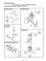
TO ADJUST ATTACHMENT
(See Fig. 18)
,',',
=,
pedal fully and set parking brake.
,,,,,
,
'
, ,u ,,,,....
HH,,H
CLUTCH
,," ....
TO ADJUST
='"'
"
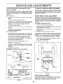
BRAKE
(See Figs. 19 and 20)
Your tractor is equipped with an adjustable brake system
which is mounted on the left side of the transaxle.
The electric clutch should provide years of service. The
clutch has a built-in brake that stops the pulley within 5
seconds. Eventually, the internal brake will wear so the
mower blades wilt not stop as recommended. Adjustments
should be made by an authorized service technician.
If tractor requires more than six (6) feet stopping distance
at high speed in highest gear, then brake must be adjusted
•
Remove four (4) hexwasher head tapping screwsfrom
shift cover plate located on top of tractor frame. Remove the cover plate,
,
Make sure attachment clutch and ignition switches are
in the "OFF" position
Adjust the three nylon Iocknuts until the space between
clutch plate and rotor measures O12 inches at all three
•
,
Loosen jam nut (A) on brake rod (B) at clevis (C) (Fig.
21). tf you find it difficult to loosen jam nut (A), remove
cover plate in L.H frame rail.
s_ot locations cut inside of brake plate
NOTE: After installing a new electric clutch, run tractor at
full throttle, and engage and disengage electric clutch 10
cycles to wear in clutch plate.
•
Rotate brake rod (B) counterclockwise, turning brake
rod out of clevis (C) four (4) to six (6) turns.
•
Start tractor with transaxle in "N" (NEUTRAL) position.
Depress clutch/brake pedal to the point where the belt
stops moving. Hold clutch/brake pedal in position by
engaging parking brake. If belt begins to move after
ROTOR
CLUTCHPLATE
next notch on parking brake.
•
2"
__
Shut engine off Rotate brake rod (B) clockwise by
hand, turning brake rod into clevis (C) until tight
Tighten jam nut (A) on brake rod (B) at clevis (C)
engaging parking brake, depress clutch/brake pedal to
If cover plate in LH
replaced.
_'-____"
__
NYLON LOCKNUT (3)
"_(
"
rail was removed it should be
SHIFT COVER PLATE
Rei_sta" shift c°ver p'ate and f°ur
14)m°unting screws
BRAKE PLATE
FIG. 18
FIG, !9
A
_
_
c
FIG. 20
17
....
TO REPLACE MOTION
Figs. 21 and 22)
=,=,=
, =.......
TO ADJUST
DRIVE BELT (See
i,,,
STEERING
WHEEL
ALIGNMENT
If steering wheel crossbars are not horizontal (left to right)
when wheels are positioned straight forward, remove steering wheel and reassemble per instructions in the Assembly
section of this manual,
Park the tractor on level surface, Engage parking brake.
For ease of service there is a belt installation guide decal on
bottom side of left footrest, It is not necessary to remove
mower.
BELT REMOVAL -
FRONT
*
Raise hood and disconnect negative ground battery
cable.
,
Set parking brake (to get belt slack).
•
Loosen (do not remove) two (2) engine pulley belt
guide bolts and swivel RH_ side of belt guide up.
Tighten L.H bolt to hold belt guide in position,,
Front wheel toe-in is required for proper steering operation,
Toe-in was set at the factory and adjustment should not be
necessary. If parts in the front axle or steering mechanism
have been replaced or damaged, check toe-in and adjust if
necessary,
idler
pulley and frame.
•
Roll belt off engine pulley,
.
Roll belt off "V" idler, flat idler and clutching
pulleys
.
Roll belt off clutch pulley-between
Pull belt off transaxle pulley,
BELT INSTALLATION -
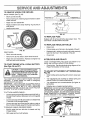
TOE-IN
ADJUSTMENT
TO CHECK TOE-IN (See Fig 23) •
.
,
WHEEL
Position front wheels straight ahead
Measure distance between wheels at front and rear of
tires (dimensions "A" and "B"),
Front dimension"A"should
be 1/8" to 1/4"less than rear
dimension "B",
TO ADJUST TOE-IN (See Figs. 23 and 24) -
•
Push belt down from engine pulley area Place back
(flat) side of belt on flat idler (flat idler is next to frame).
•
Place belt on clutching idler and over clutch pulley° "V"
(narrow) part of belt should engage clutch pulley.
•
Place belt around transaxle pulley.
should engage transaxle pulley,
.
Make sure "V" part of belt engages "V" idler,
,
Roll belt over engine pulley.
,
Loosen L.H, engine pulley belt guide bolt and swivel
belt guide on to R,H, bolt. Tighten LH and R,H, bolts
securely,
It is important that both tie rods be equat in length before
adjusting toe-in, Both tie rods should measure approximately 10-1/4" in length (see inset), Adjust if necessary_
"V" part of belt
•
Loosen jam nuts at adjustment sleeves on tie rods.
•
Adjust both tie rods equally until dimension "A" is 1/8"
to 1/4 less than dimension "B".
•
Tighten jam nuts securely,
1
B
•
Release parking brake,
IMPORTANT; CHECK BRAKE ADJUSTMENT_
FRONT OF TRACTOR
LH. BOLT
A
R,H. BOLT
FIG, 23
ENGINE
PULLEY
ADJUSTMENT
SLEEVES
TIE
ROD
ELT GUIDE
o
o
__
..........
FIG. 21
FIAT
IDLER
CLUTCH PULLEY
NUTS
1\
FIG. 24
FRONT
CLUTCHING
IDLER
TRANSAXLE
WHEEL
CAMBER
The front wheel camber is not adjustable on your tractor, If
damage has occurred to affect the front wheel camber,
contact your nearest authorized service center,
PULLEY
FIG. 22
18
....,w._.,
,.,=. ,i ,,"..,,.'l,r
'1'
I
' I'U
''=,,,1'
I'""1'_
I
I'
SERVICE AND ADJUSTMENTS
_,,
_
i_
,
i,,,i,,
TO REMOVE
WHEEL
,
i H i ,,,,,,1,1
......................
,
,m,,,,,
,
i,i
FOR REPAIRS
FRONT WHEEL (See Fig, 25) •
Block up axfe securely,
•
Remove axle cover, retaining ring and washers to allow
wheel removal,
°
Repair tire and reassemble.
"POSITIVE"(+J
(-)
FIG, 26
Replace washers and snap retaining ring securely in
axle groove
L.H, P_
Replace axle coven
WASHERS
FIG. 27
RETAINING
RING
TO REPLACE
FUSE
Replace with 30 amp automotive-type plug-in fuse_ The
fuse holder is located behind the dash°
TO REPLACE
HEADLIGHT
BULB
*
Raise hood,
,
Pull bulb holder out of the hole in the backside of the grill,
REAR WHEEL-
.
"
Block rear axle securely.
*
Replace bulb in holder and push bulb holder securely
back into the hole in the backside of the grill
Close hood,
,
Remove five (5) hub bolts to allow wheel removal.
-AXLE
COVER
FIG. 25
•
-Repair tire and reassemble. Replace and tighten hub
bolts and axte cover securely.
TO START ENGINE WITH A WEAK
'See Figs. 26 and 27)
.1,,,
ii
_,
A _
,
......................
INTERLOCKS
Loose or damaged wiring may cause your tractor to run
poorly, stop running or prevent it from starting°
BATTERY
.,,i
*
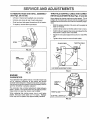
TO ADJUST
•
ATTACHMENT
LIFT SPRING (See
Fig. 28)
•
While holding spring bushing with wrench, loosen jam
nut,
•
Turn adjustment bolt clockwise to extend spring and
reduce lift effort (for heavier attachments),
°
Turn adjustment bolt counterclockwise
tachments).
(for lighter at-
•
Retighten jam nut against spring bushing,
IMPORTANT: DO NOT ADJUST FOR MAXIMUM SPRING
TENSION WHEN USING LIGHT ATTACHMENTS SUCH
AS A MOWER, ADJUST LIFT LEVER SPRING TO AID IN
LIFTING ATTACHMENT. DO NOT OVERPOWER SPRING.
WHEN REMOVING ATTACHMENT, ALWAYS ADJUST
SPRING TENSION TO iTS LOWEST POSITION,
TO ATTACH JUMPER CABLES -
•
Check wiring. See the electrical wiring diagram in the
Repair Parts section of this manual
......
CAUTION: Lead-acid batteries generate explosive gases. Keep sparks, flame
and smoking materials away from batterles.
Always wear eye protection
when around batteries,
If your battery is too weak to start the engine, it should be
recharged.
If "jumper cables" are used for emergency
starting, follow this procedure:
IMPORTANT; YOUR TRACTOR IS EQUIPPED WITH A
12 VOLT NEGATIVE GROUNDED SYSTEM. THE OTHER
VEHICLE MUST ALSO BE A 12 VOLT NEGATIVE
GROUNDED SYSTEM. DO NOT USE YOUR TRACTOR
BATTERY TO START OTHER VEHICLES,
•
AND RELAYS
Connect each end of the RED cable to the POSITIVE (+)
terminal of each battery, taking care not to short against
chassis,
ATTACHMENT
Connect one end of the BLACK cable to the NEGATIVE
(-) terminal of fully charged battery.
UFT SPRING
ADJU
BOLT
Connect the other end of the BLACK cable to a bolt on
the L,H, side of chassis, away from fue_tank and battery_
TO REMOVE CABLES, REVERSE ORDER
•
•
BI_ACK cable first from left side of chassis and fully
charged battery.
RED cable last from both batteries,
JAM NUT
19
FIG. 28
SPRING BUSHING
SERVICE AND ADJUSTMENTS
TO REMOVE HOOD AND GRILL
(See Figs. 29 and 30)
ASSEMBLY
,
Lift hood,
•
Unscrew one screw at rear of each side panel
•
Pivot hood and side panel forward and lift off tractor.
•
To replace, reverse above procedure_
THROTTLE
CONTROL
RETOR ADJUSTMENTS
Disconnect headlight wire connection°
CABLE
AND CARBU-
(See Figs. 31 and 32)
Never attempt to change maximum engine speed. This is
present at the factory and should only be changed by a
qualified service technician who has the necessary equipment_
•
Start the engine and allow it to warm up thorougNy (at
least 10 minutes),
*
Loosen clamp screw so throttle cable is free to move_
,
Hold throttfe arm against stop screw and adjust throttle
stop screw to obtain 1000-1100 RPM.
°
Adjust the tow speed adjustment screw for 1400 RPM
idle.
•
Tighten clamp screw to secure throttle cable_
SCREW
CLAM
THROTTLE
FIG. 29
WIRE
CONNECTION
\
LOW SPEED ADJUSTMENT
SCREW
FIG, 31
FIG, 30
ENGINE
CARBURETOR
Your carburetor has a fixed main jet. The idle mixture was
set for maximum efficiency at the factory and should
normallynot be disturbed lfadjustments seem necessary,
first be sure the ignition system is working properly and the
governor sensitivity is properly adjusted.
T.ROTT [%
STOP
The carburetor has a limited adjustment range between
stops _ 1/8 turn, The screw shou|d only be adjusted within
these limits; in to lean the mixture, out to richen
SCREW.._,
THROTTLEARM
When replacing idle mixture screw, turn in until lightly
seated, then turn screw back out 1-1/4 turns. Replace
limiter cap with the plastic stop approximately centered.
_'--'"
IDLERFUELUMITERCAP
FIG, 32
2O
CAB_
ENGINE
Immediately prepare your tractor for storage at the end of
the season or if the tractor will not be used for 30 days or
more.
i,,
,, i,,
FUEL SYSTEM
.............................
CAUTION:
IMPORTANT:
IT tS IMPORTANT TO PREVENT GUM
DEPOSITS FROM FORMING IN ESSENTIAL FUEL
SYSTEM PARTS SUCH AS CARBURETOR, FUEL FILTER,
FUEL HOSE, OR TANK DURING STORAGE.
ALSO,
EXPERIENCE INDICATES THAT ALCOHOL BLENDED
FUELS (CALLED GASOHOL OR USING ETHANOL OR
METHANOL) CAN ATTRACT MOISTURE WHICH LEADS
TO SEPARATION AND FORMATION OF ACIDS DURING
STORAGE.
ACIDIC GAS CAN DAMAGE THE FUEL
SYSTEM OF AN ENGINE WHILE IN STORAGE.
Never store the tractor with
where fumes may reach an open flame
gasoline in the tank inside a building
or spark, Allow the engine to cool
before storing in any enclosure,
_
, ii1,11,,
,i
NIII,I
IIIHII
TRACTOR
Remove mower from tractor for winter storage_ When
mower is to be stored for a period of time, clean it thoroughly, remove all dirt, grease, leaves, etc. Store in a
clean, dry area.
•
Drain the fue{ tank,
.
Start the engine and let it run until the fuel lines and
carburetor are empty.
Never use engine or carburetor cleaner products in the
fuel tank or permanent damage may occur.
Use fresh fuel next season,
*
Clean entire tractor (See "CLEANING" in the Customer
Responsibilities section of this manual).
•
.
Inspect and replace belts, if necessary (See belt replacement instructions in the Service and Adjustments
section of this manual).
•
.
Lubricate as shown in the Customer Responsibilities
section of this manual
•
Be sure that all nuts, bolts and screws are securely
fastened Inspect moving parts for damage, breakage
and wear Replace if necessary.
•
Touch up all rusted or chipped paint surfaces; sand
lightly before painting,
NOTE: Fuel stabilizer is an acceptable alternative in
minimizing the formation of fuel gum deposits during storage. Add stabilizer to gasofine in fuel tank or storage
container. Always foltow the mix ratio found on stabilizer
container. Run engine at least 10 minutes after adding
stabilizer to allow the stabilizer to reach the carburetor. Do
not drain the gas tank and carburetor if using fuel stabilizer.
ENGINE
Drain oil (with engine warm) and replace with clean engine
oil. (See "ENGINE" in the Customer Responsibilities
section of this manual)_
BATTERY
•
Fully charge the battery for storage.
•
After a period of time in storage, battery may require
recharging,
.
To help prevent corrosion and power leakage during
long periods of storage, battery cables should be
disconnected and battery cleaned thoroughly (see TO
CLEAN BATTERY AND TERMINALS
in the Customer Responsibilities section of this manual)
•
After cleaning, leave cables disconnected and place
cables where they cannot come in contact with battery
terminals.
.
Be sure battery drain tube is securely attached,
OIL
CYLINDERS
•
Remove spark ptug(s),
•
Pour one ounce of oil through spark plug hole(s) into
cylinder(s).
•
Turn ignition keyto "START' position for a few seconds
to distribute oil
°
Replace with new spark plug(s).
OTHER
•
Do not store gasoline from one season to another.
•
Replace your gasoline can if your can starts to rust.
Rust and/or dirt in your gasoline wilt cause problems.
-
If possible, store your tractor indoors and cover it to
glve protection from dust and dirt.
•
Cover you r tractor with a suitabie protective cover that
does not retain moisture. Do not use plastic, Plastic
cannot breathe which allows condensation to form and
will cause your tractor to rust.
IMPORTANT: NEVER COVER TRACTOR WHILE ENGINE
AND EXHAUST AREAS ARE STILL WARM.
21
,u ,,,,r,ll....
_,
U ...................
,r'
i
" I i
,,, I'l"ll'
nl Ill¸
' 'I
i,
, t
"
, i,,,,11
.....
PROBLEM
i,i
.....
"-
i
i ........
,it
CORRECTION
t
Out of fuel
2
3.
4
5
6.
7.
Engine not "CHOKED"
Engine flooded
Bad spark plug
Dirty air filter..
Dirty fuel filter
Water in fuel
89,
10
Hard to start
1
2.
3
4,
5.
6
7
8.
rllll
n
properly
Fitl fuel tank
See "TO START ENGINE" in Operation section.
Wait several minutes before attempting to start
Replace spark plug.
Clsantreplace air filter
Replace fuelfiller.
Drain fuel tank and carburetor, refill tank with fresh
gasotine and repIace fuel filter.
Check all wiring,
Contact Sears Service Center/DepartmenL
Contact Sears Service Center/Department.
,,,,i,i
H
Dirty air filter.
Bad spark plug.
Weak or dead battery
DirtyfuelfiJler.
Stale or dirty fuel.
Loose or damaged wiring.
Carburetor out of adjustment°
Engine vatves oUt of adjustment.
..............................
Engine will not turn over
1.
2
3
4.
5.
6
7.
&
9.
10.
Loose or damaged wiring.
Carburetor out of adjustment.
Engine vaives cut of adjustment.
nil
' II
•
' 'lUt
Will not start
II n i u
i,,
CAUSE
, ,H,U
Illlll,"tr
POINTS
TROUBLESHOOTING
...... i,
I lU
i
i ,,,
1.
2
3.
4
5.
6.
7.
8.
Clean/replace air rifler.
Replace spark plug.
Recharge or replace battery.
Replace fuel filter.
Drain Iuei tank and refill with fresh gaso!ine.
Check atl widng.
Contact Sears Service Center/Department.
Contact Sears Service Center/Department.
12,
Depress clutch/brake pedal
Disengage attachment clutch.
Recharge or replace battery,
Replace fuse.
Clean battery terminals.
Check alt wiring
Check/replace ignition switch.
Check/replace solenoid or starter°
Contact Sears Service CentedDepartmenL
ill
1.
2.
3
4
Clutch/brake pedat not deprassed_
Attachment clutch ts engaged.
Weak or dead battery
Blown fuss
5.
6.
7.
8.
9
Corroded battery terminals.
Loose or damaged wiring
Faulty ignition switch.
Fautty solenoid or starter.
Fautty operator presence switch(as).
3,
4
5r
6.
7.
8.
9.
Engine clicks but will not
start
1.
2.
3
4
Weak or dead battery.
Corroded battery terminals.
Loose or damaged wiring,
Faulty solenoid or starter.
1.
2
3.
4.
Recharge or replace battery.
Clean battery terminals.
Check atl widng
Check/replace solenoid or starter.
Loss of power
1.
2.
&
4.
5,
6.
7.
8
g
Cutting too much grass!too fast.
Throttle in "CHOKE" position.
Build-up of grass, leaves and trash under mower.
Dirty ,sir filter.
Low otl Isvelldirty oil
Faulty spark plug
Dirty fuel filter.
Stale or dirty fuel.
Water in fuel
1.
2.
3.
4.
5.
6
7,
8.
9.
Set In"Higher Cut" position/reduce speed.
Adjust throttle central
Clean underside of mower housing.
Clean/rapists
air filter.
Check oil level/change oil.
CIean and regap or change spark piug
Replace fuel filter.
Drain fuel tank and refill with fresh gasoline,
Drain fuel tank and carburetor, refill tank with fresh
I III
I"'
'llU
10.
11.
12.
13.
14.
15
Excessive
vibration
Sparkplug wire loose
Dirty engine air screen/fins.
Dirtyfclogged mL,fflar.
Loose or damaged wiring.
Carburetor out of adjustment.
Engine valves out of adjustment.
1.
2r
Worn, bent or loose blade.
Bent blade mandrel.
3.
Loose/damaged
I0.
11.
12.
13.
14.
15
12.
3,
part(s).
22
gasoline and replace fuel fitten
Connect and tighten spark plug wire,
Clean engine air screen_ine.
Clean/replace muffler.
Check altwiring,
Contact Sears Service Center/Department.
Contact Sears Service Center/Department.
Replace blade. Tighten blade bolt.
Replace blade mandret.
"13ghlen loose part(s). Replase damaged parts.
"['ROU
PROBLEM
LESHOOTING
CAUSE
CORRECTION
Engine continues to run
when operator leaves seat
with attachment clutch
engaged
1,
Faulty operator-safety
Poor cut - 1Lmeven
1,
2.
3.
4.
Worn, bent or loose blade
Mower deck not level
Buildup of grass, leaves, and trash under mower,
Bent blade mandrel_
Mower blades wll! not
rotate
POINTS
presence control system°
tn clutch mechanism.
I
Check wiring, switches and connections,
If not
corrected, contact Sears Service Center/Department.
1,
2,
3
4,
Replace blade. Tighten blade boil
Level mower deck.
Clean underside of mower housing,
Replace blade mandrel
1,
Obstruction
1,
Remove obstruction,
2
3.
4,
5
Mower ddve belt out of adjustment.
Worn/damaged mower drive bert.
Frozen Idler putley,
Frozen blade mandrel.
2
3
4
5_
Adjust mower dr_vebait.
Replace mower ddve belt
Replace idler pu!ley.
Replace blade mandrel.
!.
2.
3
4,
Engine speedtoo Wow,
Travet speed too fast
Wet grass,
Mower deck not level,
1
2
3
4
Place throttle control in "FAST" position.
Shift to slower speed,
Allow grass to dry before mowing.
Level mower deck
5o
6
Low/uneven tire air pressure,
Worn, bent or loose blade.
, i ,,,, ,,,,L I,
Poor grass discharge
7.
8
9
10.
i, i,
,11111.,
Headlight(s)
not working
(If _o equipped)
...................
,i,,
Buildup of grass, leaves and trash under mower.
Mower drive belt worn or out of adjustment
Blades improperly installed
Improper blades used.
IH,,,II,
i iiiiii,
,,,,IH
,i,
5
6
7,
8
9
10.
,
Check tires for proper air pressure,
Replace!sharpen blade, Tighten blade bolt.
Clean underside of mower housing,
Replace!adjust mower drive belt,
Reinstall blades sharp edge down
Replace with blades listed in this manual,
.....................................
1_
Switch is "OFF",
1,
Turn switch "ON"
2,
3,
4.
5.
Bulb(s) burned out.
Faulty light switch
Loose or damaged wiring.
Blown fusa.
2
3
4
5
Replace bulb(s)
Check!replace light switch,
Check wiring and connections.
Replace fuse.
1,
2,
Bad battery celi(s),
Poor cable connections_
1,
2.
Replace battery,
Check!clean allconnections.
3.
4,
Faulty regulator (if so equipped)°
Faulty alternator.
3
4.
Replace regulator,
Replace alternator,
iii
Battery wll! not charge
iiii
23
,,
..............
i,,i .......... ,,,,11,,i,,,111111,_l,,ull,IL ,,
$ERVNCE
24
OTE$
20 HP TRACTOR
- MODEL
NUMBER
917.250032
SCHEMATIC
REO
©
;ATTERY
j
......
RED
RED
FUSE 30 AMP,
RED
t
,
t
STARTER
BLACK
S
)R
I
BLACK
1
IGNITION
SWITCH
WHITE
RED
LiFT
SWITCH
ELECTRIC
CLUTCH
BLACK{
OPERATOR PRESENCE
RELAY
I
I 85
86 I
SEAT
SWITCH
(NOT OCCUPIED)
PTO
(DISENGAGED)
YELLOW
BLACK
RED
@
NON-REMOVABLE
CONNECTIONS
--<2>
REMOVABLE
CONNEC_ONS
WIRING INSULATED
CLIPS
i-
NOTE: if wiring insulated
clips were removed for
servicing of unit, they
should be replaced to properly secure your wiring.
OIL PRESSURE SWITCH
(ENGINE OFF)
RED
INDICATOR
tGNmON
Posrr,o.
' ON
OFF
START
SWITCH
C!RCurr
......]
BROWN
LIGHTS
C
DEPRESS FOOT PEDAL
DISENGAGE ATTACHMENT
BATTERY DISCHARGING
CHECK OIL
OFF
ON
8+I+R÷A
B÷I÷R+S
PTO SWITCH
POSITION
t
25
CIRCUIT
B+E,C+D
B+A,C+F
7
REPAIR PARTS
20 HP TRACTOR
= - MODEL NUMBER
917.250032
ELECTRICAL
B
C
14
D
E
16
F
57
G
6t
20
12
45
25
_25
_17
36
_17
54
39
62
64
48
/
/
i
7
8
13
I
56
\
37
55
\
I
I
51
I
I
t
24
l
I
30
26
58
REPAIR PARTS
20 HP TRACTOR
- = MODEL NUMBER
917.250032
ELECTRICAL
KEY PART
NO. NO.
t
2
3
4
5
6
7
8
9
10
11
12
13
t4
109310X
2683R
123620X
124211X
109555X
110712X
121537X
7603J
100541K
109596X
7192J
17011008
7319R
17190408
t5
16
17
18
19
20
21
22
23
24
25
26
27
29
30
31
32
109553X
STD511105
73951000
127385X
124372X
4t52J
108824X
71130648
STD523707
120606X
STD551237
109626X
4022J
131563
110940X
126453X
127170X
DESCRIPTION
Key
Switch, Ignition
Cover, Key Switch
Nut, Ignition
Light Package Assembly
Switch, Light
Battery
Tray, Battery
Tube, Drain
Clamp-Hose
Tie, Cable
Screw #10-24xt/2
Washer, Lock, Internal Tooth
Screw, HexWasher Head, Thread
Cutting 1/4-20x t/2
Switch, Interlock
Screw, HexWasher #10-32 x 1/2
Nut, Keps #10-32
Sensor, LowVoltage
Harness, Ignition
Bulb, Headlight
Fuse, 30 Amp
Bolt, Hex 3/8-24 x 3
Bolt, Hex 3/8-16 x 3/4
Cable, Ground
Washer, Lock, ExternalTooth
3/8
Switch, P.T.O.
Nut, Hex
Cover, Terminal
Meter, Hour
Cable, Starter
Clutch, Electric
KEY PART
NO. NO.
DESCRIPTION
33
34
35
36
37
39
40
41
42
43
44
45
46
47
48
49
50
5t
52
54
55
56
57
58
59
60
61
62
63
64
Spacer, Clutch
Stop, Clutch
Washer
Washer, Lock 3/6
Bolt, Carriage 1/4-20 x 7-1/2
Nut, Wing 1/4-20
Guard, Terminal
Bolt, Hex 1/4-20 x 3/4
Washer 9/32 x 5/8 x 16 Gauge
Nut, Hex 1/4-20
Washer, Lock 1/4
Harness, Light Socket
Switch, Seat
Clip, Insulated
Relay, Operator Presence
Key, Electric Clutch
Counterbalance, Engine
Tube
Bolt, Hex 3/8-16 x 2-1/4 Grade 5
Nut, Hex 3/8-16
Actuator, Electric (See Breakdown)
Bracket
Bolt, Carriage 3/8-16 x 1 Grade 5
Pin, Actuator
Spring, Retainer
Bulb, Light
Screw, Pan Head #10-32 x 1/2
Wiring, Lift Switch
Caps, Battery
Switch, Lift
110944X
110881X
19132203
STD551137
72240460
123198X
102476X
STD522507
STD551025
STD541025
STD551125
1t0859X
121305X
417tR
109748X
127t71X
120445X
5950J
STD523722
STD541037
124371X
677A886
STD533710
7085J
4940M
t10143X
7464'1008
!26290X
121264X
8984R
NOTE: All component dimensions
1 inch = 25.4 mm
27
given in U.S. inches
REPABR PARTS
20 HP TRACTOR
CHASSIS
== MODEL NUMBER
917.250032
AND ENCLOSURES
i
52
77
37
79
G
A
B
C
D
E
F
G
H
J
L
M
N
P
Q
R
S
3
_2
28
_ 9
@ 92
REPAIR PARTS
20 HP TRACTOR
CHASSIS
AND ENCLOSURES
KEY PART
NO, NO.
DESCRIPTION
1
2
3
5
6
8
9
!0
11
13
15
127439
124294X
105529X
STD541431
275tR
126656X
STD541437
121642X459
106202X
STD523707
17490608
16
17490616
17
18
19
20
21
22
23
24
25
26
27
28
29
30
31
32
33
34
35
36
37
39
40
41
105511X
120579X
124181X
7192J
105531X
105509X
106020X
123549X
106082X
123487X
7834R
7833R
105465X459
105466X
105464X459
110892X
110893X
7982J
74760716
73680700
108403X459
108410X459
130523
121055X
- - MODEL NUMBER
917.250032
KEY PART
NO. NO.
Seat
Pan, Seat
Bolt, Shoulder
Locknut 5/16-t8
Clip
Bracket, Pivot, Seat
Nut, Crownlock 3/8-t6
Fender
Reflector, Taillight
Bolt, Hex 3/8-16x3/4
Screw, Hex Washer Head, Thread
Roll. 3/8-16 x 1/2
Screw, HexWasher Head, Thread
Roll 3/8-16xl
Strap, Fender
Nut, Pal
Spring, Compression
Tie, Cable
Nut, Push
Bracket, Fender
Tank, Fuel
Cap, Fuel
Pad, Spacer
Clamp, Hose
Line, Fuel
Line, Fuel
Footrest, LH
Pad, Footrest
Footrest, RH
Rail, Frame, RH
Rail, Frame, LH
Drawbar
Bolt, Hex 7/16-I4 x t
Nut, Crownlock 7/16-14
Panel, Side, RH
Panel, Side, LH
Bracket, Pivot, Frame, RH
Bracket, Pivot, Frame, LH
42
43
44
45
46
47
49
51
52
53
54
58
59
62
64
70
71
72
73
74
75
77
79
80
8t
83
84
85
1060!3X459
! 10874X
120153X
108512X
108513X
110898X
132257
108067X
106091X
106090X
110350X459
3645J
8710J
19131416
t06088X
106909X
106910X
108402X
124238X
19131614
106086X
105036X
105500X
1270t8X
19131312
120068X
19171912
17490612
86
87
88
89
90
91
92
121251X
12t246X
121248X
7205041!
121249X
123740X
123976X
DESCRIPTION
Hood
Shield, Heat, Front
Grill
Bracket, Pivot, Grill, RH
Bracket, Pivot, Grill, LH
Lens
Bezei
Nut, Pal
Hinge, RH
Hinge, LH
Strap, Grill
Bushing
Stem, Fuel Tank
Washer 13/32 x 7/8 x 16 Gauge
Strip, Foam
Screw, Special
Washer
U-Clip
Cap, Spring
Washer 13/32 x ! x 14 Gauge
Foam Strip
Foam Strip
Retainer, Belt, Lower
Bolt, Shoulder 5/16q8 UNC
Washer 13/32 x '13/!6 x 12 Gauge
Knob, Seat
Washer 17/32 x 1-3/16 x 12 Gauge
Screw, Hex Washer Head, Thread
Rollo 3/8-16 x 3/4
Foam Strip
Switch, Bracket
Snap Bushing
Bolt, Carriage 1/4-20 x 1-1/4
Spacer, Split
Spring
Nut, Hex, Flange 1/4
NOTE; All component dimensions given in U.S. inches
1 inch = 25.4 mm
29
REPAIR PARTS
20 HP TRACTOR
GROUND
= - MODEL NUMBER
917.250032
DRIVE
66
/
72 73
69
32
6
71
86
85
84
94
\
.
\
59
.__103
127
OPTIONAL
IEQUIPMENT
Spark Arrester'
Kit
A
C
D
E
F
G
H
J
K
L
M
N
O
P
Q
R
S
T
I
RIEPAaR PARTS
20 HP TRACTOR.,
GROUND
- MODEL NUMBER
917.250032
DRIVE
KEY PART
NO, NO,
1
2
STD551131
131723
3
4
5
6
8
11
12
17
18
19
20
23
25
26
28
29
19131316
13280336
732206O0
7319R
110886X
STD551125
110866X
STD541437
121355X
STD551137
19131614
121063X
101344L
122825X
I22824X
STD533717
3O
31
32
36
37
38
39
40
42
43
44
45
46
47
48
49
50
5t
52
54
55
56
57
58
59
60
61
62
63
64
65
66
67
69
70
STD523707
102403X
19132616
121356X
207J
12000039
121361X
STD523715
t21357X
STD570907
101356L
104360X
121358X
19131413
121360X
110943X
STD5237t0
17190516
74780516
122253X
105598X
t06932X
STD541431
122268X
110883X
120404X
74760716
STD551143
120332X
9204H
104375X
121749X
STD571812
124215X
17720408
KEY PART
NO. NO,.
DESCRIPTION
Washer, Lock
Engine, Onan, 20 HP,
Model Number 739,11054D
Washer 13/32 x 13/16 x 16 Gauge
Pipe, Nipple
Nut, Hex 3/8-16
Washer, Lock, Internal Tooth
Muffler
Washer, Lock
Base, Engine
Nut, Crownlock 3/8-16
Pulley, Ground Drive
Washer, Lock 3/8
Washer 13/32 x 1 x I4 Gauge
Bracket, V-Pulley, Drive, Mule
Pulley, Idler
Bracket, Idler, Fiat
Keeper, Belt, Mute Drive, V-idler
Bolt, Carriage
3/8-16 x 1-3/4 Grade 5
Bolt, Carriage 3/8-16 x 3/4
idler, Flat
Washer 13/32 x 1-5/8 x 16 Gauge
Bracket, Clutch
Washer, Hardened
KIip Ring
idler, Grooved
Bolt, Hex 3/6-16 x 1-3/4
Spring, Extension
Pin, Cotter 3/32 x 3/4
Rod, Clutch
idler, Flat
Retainer Spring
Washer 13/32 x 7/8 x 13 Gauge
Retainer, Belt
Adapter
Bolt, Hex 3/8-16 x 1 Grade 5
Screw, Hex 5/16-18 x 1
Bolt, Hex 5/t6-18 x 1
Rod, Shift, Hi-Lo
Bracket, Rod, Shift
Knob
Nut, Crownlock 5/I6-18
Connecting Link
V-Belt
Bracket, Support, Transaxte
Bolt, Hex 7/16-14x I
Washer, Lock 7/16
Pulley, Transaxle
Locknut t/2-20
Shaft, Foot Pedal
Washer 25/32 x 1-1/4 x 16 Gauge
Pin, Rolt 3/16x 1-I/4
Control, Throttle
Screw, Hex, Thread Cutting
1/4-20 x 1/2
71
72
73
74
75
76
121388X
STD551237
STD541137
8883R
677A637
74370612
77
78
79
80
81
82
83
84
85
86
87
88
89
90
92
93
94
95
96
97
98
STD523708
101122M
72140405
STD541025
7229J
1685H
STD533110
5308J
7241J
STD541537
100604K
5102J
124236X
136284
634A692
7563R
12000034
1304H
3645R
105588X
7154J
99
100
101
102
103
104
105
106
108
109
t10
11 t
1t2
1t3
114
116
I18
119
120
122
124
126
127
128
129
65139
59192
214J
STD541410
633A108
2228M
74760720
t05706X
9858M!
5304J
74321016
275tR
10460tX
STD522507
73680400
73680700
76020816
101358K
19131612
STD533107
STD523715
t 10895X
120615X
13200300
13290300
DESCRIPTION
Control, Choke
Washer, Lock, External Tooth 3/8
Nut, Hex 3/8-24 UNF
Cover, Pedal
Bracket, Brake
Screw, Machine, Uncut Flat Head
3/8-16 x 3/4
Bolt, Hex 3/8-16 x 7/8
Band, Brake
Bolt, Carriage 1/4-20 x 5/8
Nut, Hex 1/4-20
Guide, Rod, Brake
Locknut 5/16-18
Bolt, Carriage 5/16-18 x 3/4
Rod, Brake
Spring, Compression
Nut, Centerlock, Hex 3/8-24
Yoke
Pin, Clevis
Cap, Plunger
Rod, Parking Brake
Bushing and Wheel Hub
Washer, Thrust, Axle
Klip Ring
Bolt, Hub
Wheel, Rear
Tire, Rear
Tube, Tire
vOptional, Service Item Only)
afve, Tire
Cap, Valve
Drum, Brake
Locknut #10-24
Gear Shift Lever Assembly
Key, Woodruff
Bolt, Hex 7/16-14x 1-!/4
Bearing, Idler
Key, Woodruff
Actuator, Switch, Interlock
Screw, Hex Fin #t0-24 x 1
Clip
Bracket, Interlock
Bolt, Hex 1/4-20 x 3/4
Nut, Crownlock 1/4-20
Nut, Crownlock 7/16-14
Pin, Cotter 1/4x 1
Bracket Assembly, Clutch
Washer 1/32 x 1 x 12 Gauge
Bolt, Carriage 5/16-i8 x 3/4
Bolt, Hex 3/8-16x 1_1/2
Nyliner
Spark Arrester Kit
Elbow, Standard
Pipe, Plug
NOTE: All component dimensions given in U.S. inches
t inch = 25.4 mm
31
REPAIR PARTS
20 HP TRACTOR
- o MODEL
NUMBER
917.250032
STEERING
!7
/
REPABR PARTS
20 HP TRACTOR
° .. MODEL
NUMBER
917.250032
STEERING
KEY PART
NO. NO.
1
2
106230X
8134H
3
4
5
6
7
8
9
10
11
12
14
I5
16
17
18
19
20
21
22
23
24
25
26
27
30
31
32
33
34
122974X
278H
9040H
t21167X
6266H
12000029
5284J
STD523707
STD54!437
5297J
5298J
74781044
STD551162
STD541062
6855M
121168X
120424X
110497X
STD551137
STD541137
5292J
108137X
19292016
121159X
102439X
I04239X
STD533710
101274N
17490612
35
36
37
38
39
40
41
42
43
102458X
12000034
121021X
100711L
19133808
121050X
9038R
105519X
120028X
KEY PART
NO. NO.
DESCRTPTION
Tire, t6 x 6°50
Tube, Front
(Optional, Service Item Only)
Front Wheel (Includes Key #4 & 5)
Fitting, Grease
Bearing
Spindle, RH
Bearing, Thrust
Klip Ring
Bracket, Axle
Bolt, Hex 3/8-16x3/4
Nut, Crownlock 3/8-16
Axle, Front
Tube, Pivot Axle
Bolt, Hex 5/8-11 x 2-1/4 Grade 5
Washer, Lock 5/8
Nut, Hex 5/8-11
Fitting, Grease
Spindle, LH
Sector Assembly
Link, Drag
Washer, Lock 3/8
Nut, Hex 3/8-24
Bushing, Beltcrank
Bellcrank
Washer 29/32x 1-1/4x 16Gauge
Rod, Tie
Bracket, Support, Steering
Bearing Flanged
Bolt, Carriage 3/8-16 x 1 Grade 5
Support, Steering
Screw, Hex Washer Head, Thread
Roll, 3/8-16 x 3/4
Shaft, Steering
Klip Ring
Wheel, Steering
Adapter, Steering
Washer 13/32x 2o3/8 x 8 Gauge
Sleeve, Steering
Bearing
Dash, Lower
Dash
44
45
46
47
48
49
105525X
19171416
STD533727
121235X
106042X012
17720408
51
52
53
54
60
6t
62
63
64
65
66
68
69
70
71
72
73
74
75
76
77
79
82
83
85
86
89
91
92
100710L
74780880
73680800
19172610
STD54t037
5213J
STD541431
7985J
65139
59192
124213X011
t06615X
2751J
109850X
109851X
7919J
73700600
STD541337
STD533107
121749X
121748X
104757X
STD523710
100207K
120t99X
12!177X
4171R
121232X
74180412
93
94
19091216
STD541425
DESCRIPTION
Bracket, Support, Dash
Washer 17/32 x 7/8 x 16 Gauge
Bolt, Carriage 3/8-16 x 2-3/4
Spacer
Cover, Gate, Shift
Screw, Hex Washer Head, Thread
Cutting 1/4-20 x 1/2
Cap, Steering Wheel
Bolt, Hex 1/2-13 x 5
Nut, Crowntock 1/2-13
Washer 17/32 x 1-5/8 x 10 Gauge
Nut, Hex 3/8-16
Bracket, Frame, Front
Nut, Crownlock 5/16-18
Support, Battery
Stem, Valve
Cap, Valve
Dashptate
Pin, Mounting, Idler Bracket
Clip
Joint, Tie Rod, Threaded, RH
Joint, Tie Rod, Threaded, LH
Rod, Tie
Nut, Hex, Jam 3/8-24 LH
Nut, Hex, Jam 3/8-24 RH
Bolt, Carriage 5/16-18 x 3/4
Washer 13/32 x 1-1/4 x 7 Gauge
Washer 25/32 x 1-5/8 x 16 Gauge
Cap, Hub, Front
Bolt, Hex 3/8-16 x 1 Grade 5
Clip 3/8
Tube
Collar
Clip
Cap, Spindle
Screw, Machine, Cross Head
1/4-20 x 1/4
Washer 9/32 x !/4 x 16 Gauge
Nut, Keps 1/4-20 UNC
NOTE; All component dimensions
1 inch = 25,4 mm
33
given in U,S, inches
RE!PAURPARTS
20 HP TRACTOR
.. = MODEL NUMBER
917.250032
STEERING
E
59
E
56
,9 36
/
0
lL:,/
3
1
16
/.31
!
18
17
J
2O
C
/
21
A
B
_S
C
D
E
39
F
I/3,
@48@ 13
@62® s2
34
@ =9
REPAaR PARTS
20 HP TRACTOR
- = MODEL
NUMBER
917.250032
STEERING
KEY PART
NO, NO.
DESCRIPTION
1
2
3
4
5
6
7
8
9
10
11
12
13
15
16
17
18
19
20
21
22
23
24
25
26
27
28
29
30
31
Handle, Adjust, Lift
Nut, Special
Rod, Adjust, Lift
Pin, Cotter 3/32 x 1/2
Spring
Washer 13/32 x 5/8 x 16 Gauge
Cover, Access
Shield, Heat, Rear
Cap, Spring
Nut, Crownlock 5/16-18
Brace, Heat Shield
Bolt, Hex l/4-20 x 1/2 Grade 5
Nut, Crowntock 1/4-20
Grommet, Split
Nut, Hex, Jam 3/8.16 UNC
Bolt 3/8-16xl-3/4Grade5
Bracket, Lift, LH
Bracket, Lift, RH
Washer 17/32 x 1-1/2 x 10 Gauge
Tube _384 x 1-1/2 x 15/16
Washer, Lock 3/8
Shaft, Lift
Trunnion, Depth Stop
Washer 15/32 x 3/4 x 16 Gauge
Klip Ring
Bracket, Lift, LH
Bolt, Shoulder
Nut, Hex, Flange 1/4-20
Link, Lift, LH
Link, Lift, RH
100734K
! 10807X
110811X
STD570907
2876H
19131016
121794X
110870X
109412X
STD541431
110904X
STD522505
73680400
110436X
STD541237
STD523717
5948J
5947J
19172410
5949J
STD551137
124217X
110810X
19t51216
12000037
7594J
7901J
STD541237
7596J
105503X
KEY PART
NO, NO.
32
34
35
36
37
38
39
40
41
46
47
48
49
50
51
52
53
54
55
4939M
123934X
19112410
STD551t3t
STD523107
105624X
STD523710
STD551050
9135R
105501X
STD533707
STD541431
74780516
126651X
STD533110
19111610
121045X
121046X
17490608
56
57
58
59
60
62
64
65
123935X
STD541037
123933X394
120529X
STD54t437
STD541437
12000022
19292016
DESCRIPTION
Retainer, Spring
Scale, Height Indicator
Washer 11/32 x 1-1/2 x 10 Gauge
Washer, Lock
Bolt, Hex 5/16-18 x 3/4
Hub, Lift Shaft
Bolt, Hex 3/8-16 x 1
Washer 17/32 x 1 x 16 Gauge
Retainer Spring
Bracket, Suspension, Mower
Bolt, Carriage 3/8-16 x 3/4
Nut, Crowntock 3/8-16
Bolt, Hex 5/16_18 x i
Guard, Belt, Engine
Bolt, Carriage 5/16-18 x 1
Washer 11/32 x ! x 10 Gauge
Panel, Side, RH
Panel, Side, LH
Bolt, Hex Washer Head, Thread
Roll 3/8-16x 1/2
Plug, Hole
Nut, Hex 3/8-16
Pointer, Height Indicator
Washer, Nylon .44 x °75 x .032
Locknut, Hex, Washer Insert 3/8-16
Nut, Centedock 3/8-16
E-Ring
Washer 29/32 x 1-1/4 x t6 Gauge
NOTE: All component dimensions given in U.S, inches
1 inch = 25.4 mm
35
REPAIR PARTS
20 HP TRACTOR
- - MODEL NUMBER
917.250032
29
80
79
78
48
62
58
.°59 57
75
70
74
7O
73
;2
72
69
25
92 93
24
f98
36
REPAnR PARTS
20 HP TRACTOR
- - MODEL NUMBER
917.250032
AYP TRANSAXLE
KEY PART
NO. NO.
1
2
3
4
5
6
7
8
4197R
12000034
4199R
4216R
4215R
4217R
6256H
74020652
9
10
1t
12
13
14
15
16
17
t8
19
20
21
22
23
24
25
26
27
28
29
30
31
7392M
6272H
4985R
6266H
42t2R
4196R
6276H
633A63
8118M
8740H1
122238X
4218R
6252H 1
7810H
6262H
7393R
992R1
6216H
4986R
122254X
6269H
5855H
122162X
32
33
34
35
36
37
38
39
6277H
4225R
7396H
4198R
4200R
7395H
121878X
122163X
40
41
42
45
46
47
48
49
50
13320400
74780526
13170100
6271H
13060200
74780524
10140500
4895H
4222R
KEY PART
NO. NO.
DESCRIPTION
Axle Shaft
Retaining Ring
Final Drive Gear
Differential Gear
Differential Pinion
Differential Carrier
AxleThrust Washer
Bolt, Hex 3/8-24x 3-1/4
(1" Thread Length)
Steel Bali
Spring Shift Fork Detent
Shift Fork, High-Low Range
Thrust Bearing Race
4th Reduction Pinion
3rd Reduction Gear Shaft
Snap Ring, Crescent Type
High-Low Range Gears
Needle Bearing
Sintered Iron Bearing
Shift Fork Shaft, High-Low Range
Differential Pinion Spacer
Differential Pinion Bushing
Gripco Centerlock Nut 3/8_24
Shift Fork, LH
Oil Seal
Sintered Iron Bearing
Shift Fork Shaft
Shift Fork, RH
Shift Shaft, High*Low Range
Oil Seal
Pressure Relief Valve
Gearcase, Reverse Idler Shaft and
Bearings, RH (Includes Key No.'s
17,18, 25, 33, 50, 63, 76, 77 & 82)
Dowel Pin
Needle Beating
Thrust Bearing Race
4th Reduction Gear Shaft
4th Reduction Gear Spacer
Thrust Bearing Race
Gearcase Gasket
Gearcase and Bearings, LH
(Includes Key Numbers I8, 25, 49,
50 (2), 51 and 52)
Pipe Plug 1/2-14 N.P.T_
Bolt, Hex 5/16-18 UNC x 1-5/8
Elbow, Street, 90 °
Oil Seal
Pipe Plug 1/4-18 N.P.T_
Bolt, Hex 5/16..18 x 1-1/2 Grade 5
Washer, Lock, Extra Heavy 5/16
Needle Bearing
Needle Bearing
51
52
53
54
55
56
57
58
59
60
61
62
63
64
1529R
8119M
4220R
4209R
4213R
4442R
4t95R
4214R
4t94R
7528R
4208R
4207R
7398H
4203R
65
66
67
68
69
70
71
4204R
2898J
4926H
4205R
4206R
1370H
633A69
72
73
74
75
76
77
78
79
80
81
82
84
85
86
87
88
89
90
91
92
93
94
95
96
97
98
208J
4201R
12000002
1153R
7392H
3990H
73220500
1167R
73360700
6270H
7384H
5384J
2978J
633A85
8739H1
4924H
19151516
110542X
19181511
75J
6274H
76020412
10040500
74760514
633A!09
122420X
DESCRIPTION
Needle Bearing
Needle Bearing
Thrust Bearing Race
3rd Reduction Pinion, Low
4th Reduction Gear
3rd Reduction Pinion Spacer
2nd Reduction Gear Shaft
Final Drive Pinion
1st Reduction Gear Shaft
1st Reduction Shaft Spacer
3rd Reduction Pinion High
2nd Reduction Gear
Needle Bearing
Low Speed Gear and 2nd
Reduction Pinion Cluster
Reverse Gear
Key, Hi-Pro 1/8 x 17/32
Snap Ring, Crescent Type
intermediate Speed Gear
High Speed Gear
Thrust Bearing Race
Intermediate and High Speed
Cluster Pinions
Input Shaft
Low Speed Pinion
E-Ring
Reverse Idler Gear
Reverse Idler Thrust Washer
Needle Bearing
Nut, Hex 5/16-18
Sealing Washer
Nut, Hex, Jam 7/16-20
Oil Seal
Reverse Idler Shaft
Gear Shift Lever, Bent
Gear Shift Cap
Gear Shift Ball Cover and Pin
Shift Lever Guide Ball, Keyed
Spring
Washer 15/32 x !5/16 x 16 Gauge
Shift Mechanism Seal
Washer 9/16 x 15/16 x 12 Gauge
Gear Shift Gate and Reinforcement
Shift Ball Cover Gasket
Cotter Pin 1/8 x 3/4
Washer, Lock 5/16
Bolt, Hex 5/16-18 UNC x 7/8
Gear Shift Lever Assembly
Transaxle Assembly (Less Brake
Drum and Shift Lever)
NOTE: Al! component dimensions given in U.S. inches
t inch = 25°4 mm
37
REPADR PARTS
20 HP TRACTOR
ELECTRIC
- - MODEL
NUMBER
917.250032
LIFT ACTUATOR
4
7
/
f
f
f
f
f
J
f
11
12
13
KEY PART
NO. NO,
1
1862J
2
3
4
5
6
7
1863J
8331J
1857J
I865J
1864J
677A149
8
674A281
KEY PART
NO. NO,
D ESCR1PTtON
Screw, Machine, Slotted Fillister
Head #10-32 x 1-5/8
Washer, Lock #10
Housing Cover
Cover Gasket
Snap Ring
Retaining Ring
Spr}ng Washer (Use 3 or 4 as
required)
Pawl and Ramp Washer
9
10
II
12
1859J
1861j
673A218
---
13
14
1860J
1858J
NOTE:
38
DESCRIPTION
Output Gear
Motor, 12 Volt
Connector Body Kit
Not Serviced Separately-Order
124371X (Complete Actuator)
Thrust Washer
Intermediate Gear
All component dimensions
1 inch = 25.4 mm
given in U.S. inches
REPAIR PARTS
20 HP TRACTOR
ELECTRIC
- - MODEL
NUMBER
917,250032
LIFT ACTUATOR
3
11
17
5
15
/
14
/
17
10
10
13
$
:,,
KEY PART
NO, NO.
1
2
3
4
5
6
7
8
9
110921X
128491
12849o
1058O6X
132663
128314
106974X
4900J
131283
|
::
DESCRIPTION
KEY PART
NO. NO.
DESCRIPTION
Decal
Decal
Decal
Decal
Decal
Decal
Decal
Decal
Decal
10
11
12
13
14
15
16
17
--
Decal Speed/Deck Size, Chassis
Decal Steering Wheel Insert
Decal Battery
Decat Operating Instructions
Decal Side Panel, LH
Decat Side PaneI, RH
Decal Model, Grill
Decal Grill and Hood
Manual, Owner's
HP, Engine
Hoed, Stripe, LH
Hoed, Stripe, RH
Grill
Side Panel
Logo, Fender
Caution
Clutch/Brake
V-Belt Drive
39
128884
132265
120960X
108456X
106813X
t06814X
132270
128257
132893
REPAIR PARTS
20 HP TRACTOR
- - MODEL NUMBER
ONAN ENGINE - MODEL NUMBER
_5_
_6
917.250032
739.11054D
I
G8
26
11
47
14
28
36
37
49
46
45
4O
REPAIR PARTS
20 HP TRACTOR
- - MODEL NUMBER
ONAN ENGINE ° MODEL NUMBER
CYLINDER
1
110-3424-_1
2
517-0048-01
3
800-0051
4
5
104-0776
101-0450
6
7
8
101-0450-02
101-0450-10
101-0450-20
101-0450-30
104-0575
101-0782
101-0439-0!
9
10
11
12
13
10t-0405
509-0041
516-0072
120-0735
110-1824
14
110o1824-02
I10-1824-05
110-1824-10
I10-1824-25
t10-0197
15
110-0197-02
110-0197-05
1t0-0197-10
110-0197_25
101-0432
16
19
20
24
26
27
28
29
30
31
32
33
36
37
739.11054D
BLOCK
KEY PART
NO. NO.
!01-0432-02
101-0432-10
101-0432-20
101-0432-30
110-3527
110-3526
526-0251
516-0141
110-3637-01
110-3709
115-0006
115-0006-02
115-0006-05
110-3479
110-3480
800-0010
110-3485
1t0-3511
509-0289
110-3181
110-3509
110-3508
917.250032
KEY PART
NO. NO.
DESCRIPTION
38
40
41
42
43
44
45
Short Block, Cylinder
(includes Parts Marked *)
* Plug, Welch, Camshaft Opening,
Zinc Plated 1-5/8''
* Screw, Cap, Hex Head
3,8-16 x 1-1/4
* Shim, Crankshaft, End Play .005"
* Bearing, Crankshaft, Rear,
Standard Size (Includes Thrust
Washer)
.002" Undersize
o010" Undersize
020" Undersize
,030" Undersize
* Washer, Thrust
* Gasket, Bearing Plate
* Plate, Bearing, Rear, Standard,
Code 11AH
* Bearing, Camshaft
*Seai, Oil, Crankshaft, Rear
* Pin, Drive, Bearing Stop
* Tube, Oil, Cylinder Block
* Insert, Valve Seat, Exhaust,
Standard Size
.002" Oversize
.005" Oversize
.010" Oversize
.025" Oversize
* Insert, Valve Seat, Intake, Standard
Size
002" Oversize
.005" Oversize
o010" Oversize
.025" Oversize
* Bearing, Crankshaft, Front,
Flanged, Standard Size
.002" Undersize
.010" Undersize
.020" Undersize
.030" Undersize
* Guide, Valve, Exhaust
* Guide, Valve, Intake
* Washer, Lock, Spring 3/8"
* Pin, Alignment, Gear Cover
Cover, Valve, Zinc Plated
Gasket, Valve Cover
Tappet, Valve, Standard Size
,002" Oversize
.005" Oversize
Valve, Intake
Valve, Exhaust
Screw, Cap, Hex Head
1/4.-20 x t-3/4"
Spring, Valve
Lock, Valve Spring
Seal, Valve, Intake
Gasket, Cylinder Head
Head, Cylinder, Right Side
Head, Cylinder, Left Side
110-3487
526-0122
800-057t
526-0063
517-0067
!10-35t0
46
168-0187
168-0189
120-0491
47
48
49
50
51
52
53
54
120-0161
740-1004
800-0007
80t-0049
526-0066
120_0140
t20-0398
t12-0264
58
112-0264-05
I12-0264-0!
112-0264-02
112-0264-03
112-0264-04
112_0229
518-0311
113-0310
113-0310-05
113-0310-10
113-0310-20
113-0310-30
113-0310-40
114-0257
59
60
61
62
63
114-0257-10
114-0257-20
114-0257-30
114-0240
123-0954
123-0952
123-0117
809-0035
64
65
66
67
68
69
_--
123-0951
123-0958
509-0117
870-0302
503_1336
503q606-01
517-0090
520-0820
55
56
57
DESCRIPTION
Washer, Valve Spring, Retaining
Washer, Flat 5/16"
Screw, Cap, Hex Head, Special 2"
Washer, Flat, Copper 1/4"
* Plug, Core Hole
Cap, Valve
Kit, Gasket:
Engine, Complete
Valve Grind/Carbon Removal
Pump, Oil (Components Not Soid
Separately)
Gasket Kit, Oil Pump
Washer, M6
Screw, Cap, Hex Head 1/4-20 x 1"
Screw, Cap, Hex Head 3,8_24 x 7/8
Washer, Flat, Copper 3,8"
Spring, Bypass Valve
Plunger, Bypass Valve
Piston, Standard Size
(Includes Pin And Rings)
005" Oversize
.010" Oversize
020" Oversize
_030" Oversize
.040" Oversize
Pin, Piston
Ring, Retaining
Ring Set, Piston, Standard Size
.005 Oversize
.010" Oversize
.020" Oversize
°030" Oversize
.040" Oversize
Rod, Connecting (Includes Bolt And
Nut) 20 Horsepower, Standard Size
.010" Undersize
°020" Undersize
.030" Undersize
Bolt, Connecting Rod, Special
Cap and Valve, Breather
Tube, Breather
Baffle, Breather Tube
Screw, Tapping, Round Head
#8 x 3/4"
Clamp, Loop, Breather Tube Cap
Screen, Breather Tube
Seal, O-Ring Breather Cap
Nut, Hex, Crown!ock
Clamp
Hose, Breather
Plug, Plastic (not shown)
Stud, Bolt, Guard Mounting (not
shown)
* Parts Included In Cylinder Block
NOTE: All component dimensions
I inch = 254 mm
41
given in US. inches
REPAIR PARTS
20 HP TRACTOR
ONAN ENGINE ,, MODEL
= .. MODEL NUMBER
NUMBER
917.250032
739.11054D
5
9
2
5
i
i
.....................
1
3
4
5
9
42
REPAIR PARTS
20 HP TRACTOR - - MODEL NUMBER
ONAN ENGINE = MODEL NUMBER 739.11054D
STARTER COMPONENTS
OIL FILTER
KEY PART
NO. NO.
KEY PART
NO, NO.
!91-1954
2
19t-1956
3
191-1931
4
191-1950
5
191-1951
6
191-1766
7
191-1810
8
191-1955
9
10
191-1947
750_1006
DESCRIPTION
Kit, Hardware, Starter (includes
Solenoid Mounting Screws, Thru
Bolts, Armature Shims, Pinion Stop
Collar, Retaining Ring, and
Solenoid Terminal Nuts)
Kit, Solenoid, Starter (includes
Solenoid and Spring Plunger)
Kit, Bushing, Starter (Includes Rear
Cap with Bushing and Front
Bushing)
Kit, Mounting Bracket (Includes
Front Bracket, Front Bushing, Dust
Seal, Thrust Washer, Cap Plug and
O.D. Pinion Seal)
Holder Brush (Includes (2) Negative
Brushes, (2) Positive Brushes and
Brush Holder)
Kit, Shift Lever, Starter (includes
Lever, Wear Plate, Rubber Plug
and Grease)
Clutch Assembly, Starter (Includes
Pinion Gear and Clutch Assembly)
Seat, Dust (Includes LD. and O.D.
Pinion Seals)
Cup, Starter Solenoid
Nut, Hex, M8
7
8
9
134-4553.50
104-0779
515-0284
6
7
8
122-0771
!22-0645
309-0546
1
2
3
4
5
6
Adapter, Oil Filter
Washer, Flat, Copper 54 6"
Screw, Cap, Hex Head 5.16-18 x !"
Drain, Oil Filter, Painted
Screw, Cap, Hex Head W/ET
#10-32 x 3,8"
Gasket, Oil Fitter Adapter
Filter, Oil
Switch, Low Oil Pressure
104-1351
516-0014
104-0043
104-0032
515-0001
104-1712
DESCRIPTION
Crankshaft (includes Key Noo 5)
Ring, Retainer
Washer, Gear Retainer, Special
Gear, Crankshaft
Key, Crankshaft Gear
Weight, Balance
CAMSHAFT
KEY PART
NO. NO.
BLOWER
!34-4633
104-0170
526-0356
526_0017
8!5-0687
122-0320
526-0065
800-0028
122_0360-50
815-0194
KEY PART
NO. NO.
NOTE: Onan part number stamped on starter nameplate
for identiifcation.
1
2
3
4
5
1
2
3
4
5
DESCRIPTION
CRANKSHAFT
NOTE: Phantomed items not for sale, for repfacement,
order complete starter.
KEY PART
NO. NO,
917.250032
1
2
3
4
5
6
7
150-0078
150-1519
150-1520
510-0015
515-0001
105-0639
105-0332
8
9
105-0541
150-0075
DESCRIPTION
Flywheel (Includes Ring Gear)
Screw, Cap, Hex Head (Special)
Washer, Fiat 7/16"
Washer, Flat 7/16"
Screw, Lock Head, Flange
#10-24 x 3/8"
Screen, Air Inlet, Painted
Gear, Ring
Key, Flywheel
DESCRIPTION
Ring, Retainer
Hub, Governor Cup
Cup, Governor
Ball, Governor
Key, Woodruff, Camshaft
Camshaft (Includes Key Number 9)
Gear, Camshaft (Includes Gear,
Spacer and Plate)
Washer, Thrust, Special
Pin, Center
NOTE; All component dimensions given in U.S. inches
1 inch = 25.4 mm
43
REPAIR PARTS
20 HP TRACTOR
ONAN ENGINE - MODEL
= - MODEL NUMBER
NUMBER
917.250032
739.11054D
12
!
4
Z2
)P
5€
44
REPAIR PARTS
20 HP TRACTOR
..., MODEL NUMBER
ONAN ENGINE - MODEL NUMBER
739,11054D
OIL BASE
KEY PART
NO. NO°
1
102-1325
2
3
4
102-1387
526-0251
800-0061
5
6
7
8
505-0110
102_0938
102-0743
102_0713
GEARCASE, IGNITION CONTROL,
ALTERNATOR AND REGULATOR
DESCRIPTION
KEY PART
NO. NO,
Base, Oil (Includes al! Plugs and
Plug Gasket)
Gasket, Oil Base
Washer 3,8"
Screw, Cap, Hex Head
3.8.16 x 3.3/4 "
Plug, Square Head 3/8"
Plug, Hex Head, Special
Gasket, Hex Head, Plug
Cup, Intake, Oil Pump
OIL FILL TUBE AND BRACKET
KEY PART
NO. NO.
123-1637
2
3
4
5
6
7
509-0142
123-1863-51
123-1685-50
509-0269
816-0576
870-0410
1
103-0799
2
3
4
5
510-0105
150-1422
150-1187
815-0046
6
7
8
9
10
11
516-0130
509-0008
510-0014
509-0040
103-0810
800-0032
12
14
15
16
17
18
21
526-0065
520-0933
850-0039
862-0015
I91-1256
332-2423
323-I257
22
23
166-0763
815-0172
24
8t5-0340
25
26
854_0010
518_0406
27
821-0008
28
29
191-1748
166-0786
DESCRIPTION
Cap and Indicator, Oil Fill (Includes
O-Ring)
O-Ring, Oil Fill Cap
Bracket, Fill Tube, Painted
Tube, Oil Fill, Painted 15.75" Long
Seal, Oil Fill Tube
Screw, Pan Head #10x 1-1/4"
Nut, Speed, Type U
IGNITION
KEY PART
NO. NO.
1
2
I60-1368
160-1345-01
3
4
5
6
7
166-0761
332-2904
16640767
167-0263
167.1615.01
167-1615-04
740-1004
166-0770
518-0515
800-0004
166-0771
815-0389
815-0650
8
9
10
11
12
13
14
917.250032
DESCRIPTION
Gasket, Plate
Plate, Ignition Plunger Cover, Zinc
Plated
Coi!, Battery Ignition (Includes Nuts)
Clip, Wire (To #1 Spark Plug Wire)
Rotor, Ignition
Plug, Spark
Cable, Spark Plug, 9"
Cable, Spark Plug, 18.5"
Washer, M6
Nut, Hex, Flange (M4 Pos. Term)
Clip, Wire
Screw, Cap, Hex Head 1/4-20 x 5/8
Nut, Hex, Flange (MS Neg. Term.)
Screw, Hex Washer Hd. 1/4-20 x 1
Screw, Hex Washer Hd. 1/4-20 x I
DESCRIPTION
Kit, Gearcase (Includes Parts
Marked*)
* Bearing, Governor Shaft
* Shaft and Arm, Governor
* Yoke, Governor Shaft
* Screw, Machine, Pan Head
#8-32 x 3/8"
* Pin, Dowel, Governor Cup Stop
* Seal, Oil, Governor Shaft
* Ball, Bearing, Governor Shaft
* Sea!, Oil, Crankshaft
Gasket, Gearcase Mounting
Screw, Cap, Hex Head
5/16-18 x 1-3/4"
Washer, Flat, Copper 5/16"
Stud, Gear Cover
Washer, Lock, #10
Nut, Hex 5/16-18
Stator (includes Terminals)
Terminal, Stator Leads
Body, Terminal Connector, Kit
(includes Terminals)
Control, Ignition
Screw, Machine, Hex Head, SelfLocking, Code 31AZ #10-32 x 1"
Screw, Hex Washer Head
#10-32 x 3/8"
Washer, Lock, Internal Tooth #10
Clip, Retaining, Control Rod To
Governor Shaft
Screw, Cap, Hex Washer Head
1/4-20 x 5/16"
Regulator, Voltage, 20 Ampere
Insulator, Ignition Module
* Parts Included In 103-0791 Gearcase.
NOTE:
45
All component dimensions given in U.So inches
1 inch = 25.4 mm
REPAIR PARTS
20 HP TRACTOR .. - MODEL NUMBER
ONAN ENGINE = MODEL NUMBER 739.11054D
917.250032
9
7
38
|
46
ill,ill,,
i
ii
ii
i ii|
REPAIR PARTS
20 HP TRACTOR - - MODEL NUMBER
ONAN ENGINE - MODEL NUMBER 739.11054D
AIR CLEANER
KEY PART
NO. NOo
1
2
3
865-0020
140-2005-50
140-1496
4
140-2522
5
870-0399
6
7
140-2493-53
815-0575
11
14
16
20
21
22
140-2025
140-2017-50
508-0021
312-0256
140-2536-01
815-0178
23
29
31
140-2536-03
140-2537
815-0463
32
33
140-2441
865-0029
BLOWER HOUSING AND GOVERNOR
DESCRIPTION
KEY PART
NO. NO.
Nut, Wing 1/4-20
Cover, Air Cleaner, Painted
Wrapper, Air Cleaner Element,
Standard Svc and XSL
Element, Air Cleaner, Standard
Capacity
Nut, Hex Washer Head, Flanged
5/16-18
Housing, Air Cleaner
Screw, Tapping, Hex Washer Head,
1/4_20 x 3/8"
Tube, Air Intake
Support, Air Cleaner, Painted
Grommet, Rubber (3/4" Hole)
Capacitor
Spacer, Air Cleaner Stud, 1" Long
Screw, Hex Washer Head, Thread
Forming #10-32 x 5/8"
Spacer, Rubber
Knob 1/4-20
Screw, Slotted Hex Washer Head
#10-32 x 3/8"
Cover, Element
Nut, Wing 1/4-20
1
2
3
134-4728-50
815-026t
134-4615-50
4
134-4796-50
5
815-0290
6
7
526-0021
821-0016
8
815-0290
9
10
11
12
13
14
332-2319
526-0018
!50-t214
153-0514
150-2345-02
815-0359
15
8!5-0510
16
I7
150-1398
150-2344-02
18
815-0436
I9
20
38
526-0021
150-1269
821-0008
57
58
403-1523-01
---
STARTER
KEY PART
NO, NO.
1
3
191-1949-07
800-0595
526-0122
917.250032
DESCRIPTION
Starter, Selenoid Shift
Screw, Cap, Hex Head
5/16q 8 x 3-1/2"
Washer, Ftat 5/16"
DESCRIPTION
Housing, Blower, Painted
Screw, Tapping, Hex Washer Head
Housing, Cylinder, Air, L.H.,
Painted
Housing, Cylinder, Air, RH,.,
Painted
Screw, Tapping, Hex Washer Head
1/4-20 x 543"
Washer, Flat 1/4"
Screw, Cap, Hex Washer Head
5/16-18 x 3/4''
Screw, Tapping, Hex Washer Head
1/4-20 x 543"
Clamp, Wire, Alternator Leads
Washer, Flat 1/4"
Spring, Governor, 5 Ball
Clamp, Cable
Bracket, Cable
Screw, Tapping, Hex Head
#10-32 x 1/2"
Screw, Tapping, Hex Head
#6-32 x 5.'8
Spring, Idle Setting
Arm, Governor Control (Without
Swive0
Screw, Cap, Hex Washer Head
1/4-20 x 1/2"
Washer, Flat, 1/4"
Bushing, Control Arm
Screw, Cap, Hex Washer Head
1/4.20 x 5/16"
Bracket, Lifting, Zinc Plated
Insulated Clip
WIRING HARNESS (6 LEADS)
NOTE: Onan part number stamped on the nameplate
for indentification,
KEY PART
NO. NO.
I
2
3
332-0819
323-1386
338-2104-02
NOTE;
47
DESCRIPTION
Housing, Receptacle
Housing, Receptacle, 6Way
Harness, Wiring, Engine
All component dimensions given in U.S. inches
1 inch = 25 4 mm
REPAIR PARTS
20 HP TRACTOR = ° MODEL NUMBER
ONAN ENGINE .. MODEL NUMBER 739.11054D
................IZ
11111
" ...........
..................
i,
8
FUEL
PUMP
AND FILTER
I
I
:i
9
,t
!
_8
6
3
8
11
12
48
917.250032
REPAIR PARTS
20 HP TRACTOR - - MODEL NUMBER
ONAN ENGINE - MODEL NUMBER 739.11054D
EXHAUST SYSTEM
KEY PART
NO. NO.
1
2
3
6
134-4254-50
134-4655-50
154-2746
800-0026
7
9
12
850-0045
134-4445-50
821-0009
13
154-2732-01
DESCRIPTION
Cover, Exhaust, L..H
Cover, Exhaust, R_H.
Gasket, Exhaust Adapter
Screw, Cap, Hex Head
5/16-t8 x 3/4"
Washer, Lock, Spring 5/16"
Support, Exhaust Cover
Screw, Hex Washer Head
1/4-20 x3/8"
Manifold, Exhaust
FUEL PUMP AND FILTER
KEY PART
NO, NO.
1
2
3
503-0707
149-2187-01
815-0555
4
5
6
7
8
9
503-0707
503-073I
149o1321
503-0301
503-0731
I49-2206-01
DESCRIPTION
CHOKECONTROL
(FRONT PULL)
KEY PART
NO. NO.
DESCRIPTION
1
2
3
4
5
526-0140
153-0523
153-0500
153_0524
821-0004
6
7
8
9
815-0480
854-0010
152-0155
815-0693
10
11
516-0059
815-0359
12
153-0514
146-0496
2
4
5
6
7
154_0733
740q006
154-0275
140q006
800_0032
800-0033
10
12
154-2495
518-0004
13
14
15
16
17
150-2460
509-0145
526-0113
503-1577
150-2409
Washer, Flat #10
Lever, Choke
Link, Choke
Bracket, Choke Cable
Screw, Cap, Hex Washer Head
#10-32 x t/4"
Screw, Shoulder #10-32 x .34"
Washer, Lock, IT #t0
Swivel, Choke Lever
Screw, Machine, Hex Head
#8-32 x .375"
Pin, Cotter
Screw, Tapping, Slotted Hex
Washer Head #10-32 x 7/8"
Clip, Choke Cable
CARBURETOR
Hose, 12" (Cut to Desired Length)
Pump, Fuel, Vacuum
Screw, Tapping, Pan Head
# 10-24 x 5,8"
Line, Pulse (Cut to 7" Long)
Clamp, Hose 1/2"
Cap, Fuel Fitting
CIamp, Hose
Clamp, Hose 1/2"
Fitter, Fuel
KEY PART
NO. NO.
--
146-0496
1
146-0437
2
146-0500
3
5
6
7
154_0733
146-0425
145-0391
146-0433
INTAKE MANIFOLD
KEY PART
NO, NO.
917.250032
DESCRIPTION
Carburetor, Complete, 20
Horsepower (Includes Mounting
Gasket, Elbow and O-Ring)
Gasket, Carburetor to Adaptor
Washer, Flat, M8
Manifold, Intake (Un-Tapped Boss)
Washer, M8
Screw, Cap, Hex Head
5/16-18 x 1.75"
Screw, Cap, Hex Head
5/16-18 x 2"
Gasket, Manifold to Block
Clip, Retaining, Control Rod to
Carburetor
Rod, Governor Control
O-Ring
Washer, Fiat 5/16"
Hose, Fuel 30"
Spring, Governor Rod
146-0435
146_0503
10
146-0347
DESCRIPTION
Carburetor, Complete, 20
Horsepower (Includes Mounting
Gasket)
Float Kit (includes Float, Pin And
Valve)
Kit, Repair (Includes Screw and
Plug Package, Gasket Package,
Float Valve, Idle Adjust Needle and
Spring, Mounting Gaskets and Idle
Limit Cap)
Gasket, Carburetor Mounting
Jet, Idle
Jet, Power
Kit, Shaft, Choke (Includes Choke
Valve, Valve Set Screw and Air
Filter)
Kit, Lever, uAh o k e (Includes Choke
Lever Ring, Choke Spring and
Choke Collar)
Kit, Shaft, Throttle (Includes Valve
Set Screw, Air Filter and Throttle
Valve)
Jet, Fixed, High Altitude Kit (For
Altitudes Greater Than 5000 Feet)
NOTE: All component dimensions given in US. inches
1 inch = 2&4 mm
49
SERVICE NOTES
5O
SUGGESTED GUIDE FOR SIGHTING SLOPES FOR SAFE OPERATION
ONLY RIDE UP AND DOWN HILL,
NOT ACROSS HILL
SIGHTING
FIDE
SIGHT AND HOLD THIS LEVEL WiTH
SKY LINE OR TREE.
ol
/
15 ° MAX.
ii
h
M AA,
_ _
I_
ii
'1'r"11111"1
'll"l'r'l'"rl
i,ii i
I
_,,M, I....
I
,
.......
Operate your Tractor up and down the face of slopes (not
greater than 15°), never across the face. Make turns gradually to prevent tipping or loss of control. Exercise extreme
caution when changing direcbon on slopes.
!
®
S A/ S
OWNER'S
MANUAL
MODEL NO.
917.250032
2O HP IC
ELECTRIC START
6 SPEED TRANSAXLE
GARDEN TRACTO
Each tractor has its own model number.
number.
Each engine has its own model
The Model Number for your tractor will be found on the model plate
located under the seat.
The model number for your engine will be found on the blower housing of
the engine.
All parts listed herein may be ordered from any Sears Service Centre
and most Retail Stores.
HOW TO ORDER
REPAIR PARTS
WHEN ORDERING REPAIR PARTS, ALWAYS
ING INFORMATION:
• PRODUCT-
GIVE THE FOLLOW-
LAWN TRACTOR
• MODEL NUMBER - 917,250032
• ENGINE MODEL NUMBER - 739.11054D
• PART NUMBER
- PART DESCRIPTION
Your Sears merchandise has added value when you consider Sears has
service units nationwide staffed with Sears trained technicians,,, professional technicians specifically trained to insure that we meet our pledge
to you, we service what we sell,
Sears, Roebuck
132893 Rev. 1
2.26°92
and Co., Chicago,
IL 60684 U.S.A.
PRINTED IN U.SA,