1
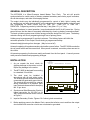
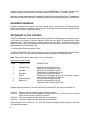
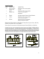
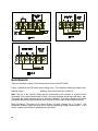
Master Time Clock
MTC-6000
Users Manual
Midwest Time Control
Phone (972)987-4408
Toll Free (888)713-0373
FAX (877)720-9291
www.midwest-time.com
[email protected]
TABLE OF CONTENTS
TOPIC
PAGE
GENERAL DESCRIPTION
1
INSTALLATION
1
FRONT PANEL CONTROLS
2
PROGRAMING
1. Set UP
2. Security Access Code
3. Set Current Time & Date
4. Set Holiday Schedule
5. Output Circuit Programing
6. Review & Cancel
7. Bulk Memory Erase
8. Memory Full
9. Lamp Test
10. Daylight Savings Time and 12/24 Display Selection
11. Baud Rate Selection
3
3
3
4
4
4
5
7
7
7
7
7
EQUIPMENT WARNING
8
SECONDARY CLOCK CONTROL
1. Synchronous Wired Secondary Clocks
2. Minute Impulse Secondary Clocks
8
8
9
MAINTENANCE
10
SPECIFICATIONS
11
OPTIONAL EQUIPMENT
11
Copyright 2002 by Midwest Time Control, Incorporated. All rights reserved. No part of
this publication may be reproduced, stored in a retrieval system, or transmitted in any form
or by any means without the prior written permission of Midwest Time Control,
Incorporated.
While every precaution has been taken in the preparation of this
publication, Midwest Time Control, Incorporated assumes no responsibility for errors or
omissions. Neither is any liability assumed for damages resulting from the use of the
information contained herein.
Rev. 1.1
0
GENERAL DESCRIPTION
The MTC-6000 is a Micro-Processor based Master Time Clock. The unit will provide
synchronization for a wide variety of industry standard secondary wall clocks, payroll recorders,
time & date stamps, and other time keeping devices.
The output circuits may be individually programmed for control of bells, lights, heating and
air conditioning, and other devices which can be scheduled for operation based on the time and
day. Programing for these circuits may be TIME ON - TIME OFF or TIME ON DURATION. Programing can be by individual day, 5 day (Mon.-Fri.), or 7 day.
The clock time base, in normal operation, is synchronized with the 60 Hz AC power line. During
power failures, the time base is accurately maintained by a back up battery powered oscillator.
The back up battery system uses a lithium energy cell with a design life of ten years. The battery
maintains timing and circuit programing during a loss of primary power.
Holidays may be programmed 12 months in advance. The Holiday feature will inhibit the
automatic operation of the Output Circuits during a programmed holiday.
Automatic daylight savings time changes. (May be turned off)
Automatic updating of Impulse secondary clocks after a power failure. The MTC-6000 records the
time of power failure and the current time. When power is restored, correction pulses are sent to
the clocks.
All operator programing functions are easily performed from the front panel. A security access
code prevents unauthorized programing changes.
INSTALLATION
1.
As you unpack the clock, check for
shipping damage to the carton or clock.
Report any damage to the carrier.
115 VAC
POWER INPUT
LINE CORD
INPUT/OUTPUT TERMINAL STRIP
RS232 RS232 RS485
FUSES
2.
The MTC-6000 is designed for mounting
in a standard 19 inch rack.
3.
The clock must be installed in
accordance with all local wiring codes.
The chassis ground connection must be
connected to a good earth ground circuit.
The terminal strip provided for external
wiring connections is a pressure plate
type, the terminals are rated for clamping
two 12 ga. wires.
4.
Synchronous Wired Secondary Clocks: A
typical connection for 120 VAC or 24
VAC synchronous wired clocks is shown
at Figure 2.
5.
Impulse Secondary Clocks: Figures 5 & 6 show typical connections.
6.
Before applying power to the Master Clock, assure that all wire runs to and from the output
circuits and clock correction circuits are not shorted or grounded.
1
FRONT PANEL CONTROLS
1.
The ENTER button is used to enter selected data into the memory. This button is active in
the program mode.
2.
The CANCEL button is used in the review mode to cancel programmed times and dates
that are no longer needed. It is also used to exit the program mode and return the clock to
normal operation.
3.
The AHEAD and BACK buttons are used to increment the display to the time or date to be
programmed. They are also used in the Review mode to observe multiple programmed
times for the output circuits and multiple holidays. These buttons are active in the program
mode.
The MODE button is used to select the functions to be programmed or reviewed.
An illuminated indicator will show the selected mode. Each time the MODE button is pressed,
the next indicator in sequence will be illuminated. The Time Set function allows the
setting of current time, day, month, date and year. The Holiday function allows setting of
holiday dates. The Duration, On and Off modes are used to program the output circuits.
The Erase mode is used to bulk erase all programmed memory times and dates except
the current time and date. The MODE button is active in the program mode.
4.
5.
The REVIEW button is used in conjunction with the MODE button to check the
programmed times and dates. The review button is a push ON push OFF control, it must
be turned OFF to advance the MODE function. It is active in the program mode.
6.
The SELECT button is used with the mode function to program the month, date and year in
the Time Set mode, and the beginning and ending month and date in the Holiday mode. The
SELECT button is also used in the review mode to observe the beginning and ending dates
of holidays. This button is active in the program mode.
7.
The CIRCUIT button is used in the Duration, On and Off modes to select the output circuit to
be programmed. It is active in the Duration, On and Off modes.
8.
The DAY button is used in the On and Off modes to select the appropriate day or days for
programing the output circuits. It is used in the Time Set mode to set the current day of the
week.
9.
The IMPULSE SECONDARY CORRECTION switch is used as an aid for initial
synchronization of secondary impulse clocks. Placing the switch in the RAPID position
causes the clocks to advance to the 58th or 59th minute at a rate of 30 steps per minute.
Returning the switch to the OFF position returns control of the secondary clock to the Master.
Placing the switch in the HR/MIN position causes the clocks to advance at the rate of 30 steps
per minute until the switch is returned to the OFF position. This switch is active in the
program Time Set mode. This switch must be in the OFF (center) position except while
advancing the Impulse Secondary Clocks.
10. The WIRED SYNC SECONDARY CORRECTION switch is used as an aid for initial
synchronization of secondary wired synchronous clocks. Placing the switch in the HOUR
position sends one hourly correction signal to the secondary clocks. Placing the switch to the
12 HOUR position sends one 12 hour correction signal to the secondary clocks. Move the
switch to OFF to return secondary clock control to the master. This switch is active in the
program Time Set mode. This switch must be in the OFF (center) position except while
advancing the Wired Synchronous secondary clocks.
11. The CIRCUIT CONTROL switches are provided for manual control of the output circuits. The
OFF position turns the output circuit OFF regardless of the programing. The AUTO position
2
places that output circuit under control of the program. The ON position places that output
circuit ON regardless of the programing.
PROGRAMING
1.
SET UP
After the initial installation, the clock must be tailored for the desired operation. All setup is done
from the front panel using access codes and the display. The following options are
programmable:
Daylight Savings Time ON or OFF (Default is ON)
12/24 Display (Default is 12 Hour format)
Synch-Wired Clock Type (Default is Midwest Time Control Clocks)
Impulse Clock Type (Default is 59 minute, no 12 hour correction)
BAUD Rate (Default is 9600 BAUD)
2.
SECURITY ACCESS CODE
A Security Access Code must be entered before a time set, a program change, addition or review.
The code is a simple and easily remembered front panel button sequence (ENTER, BACK,
CANCEL and AHEAD). When these buttons are pressed in the correct sequence, the Time Set
indicator will illuminate. Program changes can be made any time the program indicators are
illuminated. To leave the Program mode, press the CANCEL button. This restores the unit to
normal operation. The Program Control mode will time out automatically 90 seconds after the last
button is pressed. This prevents leaving the clock unattended in the program mode. A Program
Indicator must be illuminated during all programing operations.
For units equipped with the RS232-COM Options, the program mode may not be accessed while
the unit is communicating with a remote device.
3.
SET CURRENT TIME & DATE
Note: The AHEAD/BACK buttons reset the seconds counter to zero as the button is released.
This feature can be used to accurately synchronize the Master Clock with other timekeeping
devices.
STEP
1
2
3
4
5
6
7
8
9
10
11
PRESS
MODE
AHEAD/BACK
SELECT
AHEAD/BACK
SELECT
AHEAD/BACK
SELECT
AHEAD/BACK
DAY
CANCEL
INDICATION
COMMENT
TIME SET
TIME SET
Enter Security Access Code
Set Current Time (Note PM Ind)
MONTH
Set Current Month (1=Jan. 12=Dec.)
DATE
Set Cur. Date
YEAR
Set Cur. Year, 01=2001
Set Cur. Day of the week
Return to normal operation
3
4. SET HOLIDAY SCHEDULE
Note: Each Holiday must be programmed with a beginning and ending month and date.
Beginning and ending dates can not be the same.
STEP
PRESS
INDICATION
COMMENT
1
2
TIME SET
HOLIDAY, BEGIN,
MONTH
Enter Security Access Code
MODE
3
AHEAD/BACK
4
5
6
7
8
9
10
11
SELECT
AHEAD/BACK
SELECT
AHEAD/BACK
SELECT
AHEAD/BACK
ENTER
CANCEL
Set month of holiday
(1=Jan. 12 = Dec.)
BEGIN, DATE
Set date for first day of holiday
END, MONTH
Set month of holiday ending
END, DATE
Set date for first day of normal operation
The display will blank momentarily
Return to normal operation
A total of ten holidays may be programmed by repeating steps 3 thru 10. All holiday starting
and ending dates must be within the next twelve calendar months. Operation of the output
circuits is inhibited During holidays.
5. OUTPUT CIRCUIT PROGRAMING
All output circuit programs entered will remain in the memory until cancelled.
All output circuits with a programmed ON time must have a programmed OFF time or DURATION.
Assume circuit 1 is to ring a bell for 10 seconds Monday thru Friday at 8:00 AM, 12:00 Noon, and
4:00 PM.
STEP
1
2
3
4
5
6
7
8
9
10
11
12
13
14
4
PRESS
MODE
CIRCUIT
AHEAD/BACK
ENTER
MODE
DAY
AHEAD/BACK
ENTER
AHEAD/BACK
ENTER
AHEAD/BACK
ENTER
CANCEL
INDICATION
COMMENT
TIME SET
DURATION
CIRCUIT 1
Enter security access code
Set display to 10 (Range = 1-59 Sec.)
Display will blank momentarily
ON
MO,TU,WE,TH,FR
Set time to 8:00 AM
Display will blank momentarily
Set time to 12:00 Noon (PM Ind. ON)
Display will blank momentarily
Set time to 4:00 PM
Display will blank momentarily
Return to normal operation
Circuit 2 is to turn on a light at 7:45 AM Monday and off at 5:15 PM Monday.
1
2
3
4
5
6
7
8
9
10
11
12
MODE
CIRCUIT
DAY
AHEAD/BACK
ENTER
MODE
CIRCUIT
DAY
AHEAD/BACK
ENTER
CANCEL
TIME SET
ON
CIRCUIT 2
MO
Enter security access code
MO = Monday
Set time to 7:45 AM
Display will blank momentarily
OFF
CIRCUIT 2
MO
Set time to 5:15 PM
Display will blank momentarily
Return to normal operation
Circuit 3 is to turn on the outside lights at 6:00 PM and off at 10:30 PM
every day.
1
2
3
4
5
6
7
8
9
10
11
12
MODE
CIRCUIT
DAY
AHEAD/BACK
ENTER
MODE
CIRCUIT
DAY
AHEAD/BACK
ENTER
CANCEL
TIME SET
ON
CIRCUIT 3
Enter security access code
SU,MO,TU,WE,TH,FR,SA
Set time to 6:00 PM
Display will blank momentarily
OFF
CIRCUIT 3
SU,MO,TU,WE,TH,FR,SA
Set time to 10:30 PM
Display will blank momentarily
Return to normal operation
When programming multiple functions, step 1 is only necessary at the beginning of the first
program and step 12 at the end of the last program.
6. REVIEW AND CANCEL
Note: programmed holiday dates and output circuit days and time may be cancelled while
in REVIEW by pressing the CANCEL button while the date, day or time to be cancelled is
displayed. Do not attempt to leave the program mode while the REVIEW Indicator is ON, the
CANCEL button is used in the REVIEW mode to cancel programmed dates and times. To leave
the program mode when in REVIEW, press the REVIEW button to extinguish the REVIEW
Indicator, then press the CANCEL button.
5
REVIEW OUTPUT CIRCUIT PROGRAMING
1
2
3
4
TIME SET
MODE
REVIEW
CIRCUIT
5
6
7
8
REVIEW
MODE
REVIEW
CIRCUIT
9
DAY
10
11
12
13
REVIEW
MODE
REVIEW
CIRCUIT
14
DAY
15
16
REVIEW
CANCEL
Enter security access code
DURATION
REVIEW
CIRCUIT 1, 2, 3, 4,
5, or 6
ON
REVIEW
CIRCUIT 1, 2, 3, 4,
5, or 6
SU, MO, TU, WE,
TH, FR, or SA
OFF
REVIEW
CIRCUIT 1, 2, 3, 4,
5, or 6
SU, MO, TU, WE,
TH, FR, or SA
Any programmed duration will
be displayed.
Review off
Programmed ON times will be displayed
for each day. Multiple ON times may be
checked by using the AHEAD or BACK
button at each day.
Review off
Programmed OFF times will be
displayed for each day. Multiple OFF
times may be checked by using the
AHEAD or BACK buttons at each day.
Review off
Return to normal operation
When reviewing the output circuit program, the scheduled event times are displayed in
chronological order, not in the order programmed.
REVIEW HOLIDAYS
STEP
PRESS
1
2
3
MODE
REVIEW
4
SELECT
5
AHEAD
6
SELECT
7
8
REVIEW
CANCEL
INDICATION
COMMENT
TIME SET
HOLIDAY
REVIEW, BEGIN,
MONTH, DATE
END, MONTH, DATE
Enter Security access code
Holiday Starting month and
date is displayed
Holiday Ending month and date is
displayed
BEGIN, MONTH, DATE Next Holiday Starting month and date is
displayed
END, MONTH, DATE Holiday Ending month an date is
displayed
Review off
Return to normal operation
Repeating steps 5 and 6 will display all programmed holiday beginning and ending dates.
6
7. BULK MEMORY ERASE
STEP
1
2
3
4
PRESS
MODE
ENTER
INDICATION
COMMENT
TIME SET
ERASE
Enter security access code
CANCEL
The display will show :88 for approx. 5
seconds. The mode will revert to Time
Set with the current time and day
displayed. All user programmed
events will be erased except the
current time, day and date.
Return to normal operation.
8. MEMORY FULL
An attempt to program times and dates in excess of the memory capacity will be indicated on the
Display by a :99. This indication appears with the first program attempt in excess of the memory
capacity.
9. LAMP TEST
The lamp test is a method of turning on all of the front panel indicators except Circuit Status. This
test provides a simple test to indicate proper circuit operation. Press the following front panel
buttons in sequence; (ENTER, BACK, CANCEL & REVIEW). All front panel indicators except
circuit status will illuminate. Press CANCEL, indicators will return to normal condition.
10. DAYLIGHT SAVINGS TIME SELECTION AND 12/24 DISPLAY SELECTION
A special access code is required to set the Baud Rate. The code is a four button sequence
which must be entered in the correct order (ENTER, BACK, CANCEL, DAY).
When the access code is entered, the display will indicate the current status of the daylight
savings time and the 12/24 display. To change the Daylight Savings Time selection use the
AHEAD button.
0:
1:
enables Daylight Savings time to the current legislated dates.
disables the Daylight Savings Time correction.
To change the 12/24 Display Selection use the BACK button.
:0
:1
12 hour display format
24 hour display format
When the desired selections are indicated, press the ENTER button.
11. BAUD RATE SELECTION
For units equipped with a communications port (RS232 or RS485 Options) the baud rate must be
set. The available baud rate settings are 1200, 2400, 4800 and 9600. The rate set at the Master
Clock must match that of the communicating device.
7
A special security access code is required to set the Baud Rate. The code is a four button
sequence which must be entered in the correct order (ENTER, BACK, CANCEL, BACK).
When the access code is entered, the display will indicate the current Baud Rate. To change the
Baud Rate, use the AHEAD button. When the desired rate is indicated, press the ENTER button.
EQUIPMENT WARNING
Remote equipment controlled by this clock should have a warning sign to indicate that the
equipment is remotely controlled. Primary power should be removed from that equipment prior
to any maintenance or repair operations.
SECONDARY CLOCK CONTROL
The MTC-6000 Master Time Clock controls and synchronizes a wide range of secondary clocks.
It will control one variety of Minute Impulse Clocks and one variety of Synchronous Clocks
simultaneously. The Time display is used to select the clock types. The Minutes side of the
display is used to select the Synchronous-wired clock type and the Hours side of the display is
used to select the Impulse clock type.
1. Synchronous Wired Secondary Clocks
The MTC-6000 Master Clock will synchronize a variety of industry standard Synchronous Wired
secondary clocks. The unit may be programmed by the user for the following clocks:
Note: The clock selection code is set to 0: 0, at the factory.
Synchronous Clock Codes
CODE
CLOCK TYPE
CORRECTION
:0
Midwest Time
:1
Standard
:2
Standard
W/Aux
:3
:4
National Hourly
National 12
Hourly-8 Seconds @ XX:57:54,
Twelve Hour-14 seconds 5:57:54
Hourly-35 seconds @ XX:59:25,
Twelve Hour-12 minutes @ 5:12:00
Hourly-35 seconds @ XX:59:25,
Twelve Hour-12 minutes @ 5:12:00, Run Motor power is
removed from XX:59:00 to XX:00:00
Hourly-35 seconds @ XX:00:00
Hourly-25 seconds @ XX:00:00,
Twelve Hour-25 minutes @ 6:00:00
Simplex wired synchronous, Cincinnati D10 and Cincinnati D12 wall clocks use Code :00.
Code :01
Code :02
Code :03
Code :04
Does not correct the second hand for these clocks.
Requires the use of the highest numbered output circuit. Place the Circuit Control
switch for this circuit to the AUTO position.
The second hand on these clocks is not correctable.
The second hand on these clocks is not correctable.
Refer to figure 2 & 3 for Code :00, :01, :03 & :04 connecting diagram. Refer to figure 4 for Code
:02 connecting diagram.
8
Impulse Clock Codes
CODE
CLOCK TYPE
CORRECTION
0:
ASC-3 or ASC-4
Midwest Time
59th Minute 2 Wire reverse polarity
or 3 wire
1:
ASC-6
Midwest Time
59th Minute 2 Wire reverse polarity
12-hour correction @ 5:00
2:
58th Minute
3:
Special
No Rapid correction Pulses or Polarity Reversal
4:
Lathem
59th Minute 2 Wire reverse polarity
12-hour correction @ 6:00
5,
Bi-Polar
Each minute pulse is the opposite
polarity of the previous pulse
Refer to figure 6 for connection of 2 Wire Reverse Polarity Minute Impulse Clocks; (58th Min.),
(59th Min.) or (59th Min. with 12 Hour Update).
Refer to figure 5 for connection of 3 Wire Minute Impulse Clocks: (58th Min.) or (59th Min.).
To select the code, enter the special four button access code (AHEAD, CANCEL, BACK &
ENTER) in that sequence. The Digital Display will indicate the code numbers. The BACK button
will select the desired synchronous-wired correction code. The AHEAD button will select the
desired impulse clock correction code. Press ENTER and the unit will be restored to normal
operation. The unit will automatically return to normal operation 90 seconds after the last button
is pressed with the last code displayed on the digital indicator being the selected code.
9
MAINTENANCE
There are a limited number of field maintenance items in the MTC-6000.
Fuses - Located on the PCB under the insulating cover. The ratings are listed on the back cover.
Impulse Relays
Midwest Time Control Part No. 530001-02
Note: The life of the Impulse Relays will be determined by the number of Impulse Clocks
connected. At the rated contact load (10 Amp.), the relay contacts should last more than 1 year.
The relays are socket mounted and may be easily replaced. The relays should be set up for
scheduled replacement approximately once per year to avoid failure at an inopportune time.
Back Up Battery: The battery is a Lithium Energy Cell with a design life of 10 years. The
symptoms of battery failure will be a loss of time or programing during a power failure. If this
occurs, contact your dealer for replacement instructions.
10
SPECIFICATIONS
Power requirements
Program Capacity
Holidays
Operating Temp.
Storage Temp.
Humidity
Weight
115 VAC, 60 HZ, 15 Watts Max.
2691 Events
10 Holidays (Holidays may be multiple days)
0 to 60 Deg. C
-30 to 75 Deg. C
95% non-condensing
12 Lbs.
Serial Communications*
This factory installed option provides two RS232 ports and one RS485 port.
RS232
Port 1 is used to communicate with a computer, whose time is synchronized with the Master Clock.
With our software, the output circuits may also be programmed from the computer terminal.
Port 2 can be used to communicate with a NIST Telephone Modem Clock.
RS485
This output port is designed to communicate with our digital clocks and used to synchronize the
time in multiple computer installations.
* Purchasing one of our software packages is required to control some of these features.
11
NOTES:
12
WARRANTY
Midwest Time Control warrants the MTC-6000 Master Clock to be free of defects
in materials and workmanship for a period of one year from the date of delivery to
the purchaser. This period may be extended to one year from the date of
delivery to a distributors vendee, however in no event will the warranty be
extended for more than one year from the date of installation or two years from the
date of shipment from the factory whichever is sooner.
We also warrant that if operated properly, the unit will operate within the advertised
specifications for the stated warranty period. Excluded from this warranty are fuses
and socket mounted relays. These are considered normal maintenance items.
The liability of Midwest Time Control under this warranty shall be limited to
repairing or replacing a unit proved to be defective and returned to us with
transportation charges prepaid within the stated warranty period.
This warranty is in lieu of all other warranties, express or implied and constitutes
all of our liabilities to the purchaser or user. We assume no liability for
consequential damages, for anticipated or lost profits, incidental damages or loss
of time or other losses incurred by the purchaser, user or any third party in
connection with the product covered by this warranty.
This warranty will be void for any product with defects which have been caused by
abuse, neglect, improper installation, unauthorized repair or modification.
For return authorization under this warranty, contact:
Toll Free: 888-713-0373
Phone: 972-987-4408
Fax:
877-720-9291
www.midwest-time.com
EMAIL: [email protected]