1
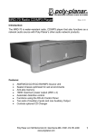
Bogen’s Self-Amplified System Design
As Easy As Always
Bogen's Self-Amplified Paging Systems feature some
unique technologies that not only make them easier to
install and operate more efficiently, but system design
is the same as with conventional self-amplified speaker
systems. In this catalog you will find the products needed
to design a self-amplified paging system that meets
your application's requirements.
• Telephone Interfaces, Paging Controllers,
and VOIP Products (pages 2-4)
• Volume Control and Buffer/Expander (page 5)
• Horn Speakers (pages 6-7, 9)
• Ceiling Speakers (page 8)
• Wall Baffle Speakers (page 10)
• Power Supplies (page 11)
• Tuners, Receivers, and Microphones (page 12)
• Paging Electronics (page 13)
Design the system yourself or take advantage of
Bogen's Free Design Service.
Free Design Service
Let Bogen design it for you!
Bogen’s Free Design Service was created to assist with the design
of paging systems for any and every project encountered.
It’s fast, comprehensive, and FREE. So let us design it for you!
The Free Design Service provides:
• Speaker Placement Design
• Complete Bill of Material – This includes product description,
model number, and quantity. We can even fax it to the distributor
of your choice for pricing, if you wish.
• Connectivity Drawings
• Scope of Work
• Detailed Assumptions
• Red-lined Blueprints (blueprints must be supplied; AutoCAD
blueprints accepted)
Here’s how the Free Design Service works:
• You provide information about the project. For large or complex
applications, your local Bogen Field Sales Manager can visit the site
for exact specifications.
No application is too big, small, simple,
or complex for Bogen paging products.
Call 1-800-999-2809 (option 2)
for more information or to send in a project for us to work on right now.
• Bogen will provide you with a working technical bid response
document... and then all you have to do is deliver it.
A copy of the bid will also be sent to your local Bogen Field Sales
Manager for immediate follow-up, and to see if you have
questions or need additional assistance.
Bogen Introduces... The New Art of Paging
Next Generation
Paging Technology
• Digital switching amplifier technology in SAH model
horns consumes significantly less current*
• Controlled dispersion SAH horn shape for
better intelligibility
• Operates with continuous background music
and in higher ambient temperatures
• BUFEX Emergency Volume control bypass function
• Multiple location paging using Ethernet network
*When compared to conventional analog self-amplified horns
Easy To Install
• No special wiring needed — use standard,
unshielded CAT3 to CAT6 wiring
• Reduced current demand of SAH horns allows
longer wire runs
• Telephone interfaces connect directly to any of five
common telephone port interface types,
including station ports
• Adjust zone and system volume quickly and easily,
using master controls on telephone interfaces
Expands Easily
• Plug-in zone modules on UTI312 allow simple
zone expansion anytime
• Fully compatible with other manufacturers’
self-amplified systems for replacement or
expansion (using 24V DC power)
More Flexibility
• Programmable dialing plan for zones and zone
groups on the UTI312
• DTMF programming of tones, zones, and features
• Select from 2 BGM sources per zone on the UTI312
• C-Form contact closure per zone
• One system provides both paging & background music
Reliability You Can Trust
• Full Two-Year Product Warranty
• Interfaces and power supplies carry all required
UL and FCC approvals
• Bogen has over 70 years of experience developing
products for the telephone paging, commercial
audio, and pro audio industries
Telephone Interface
Programmable AUX Relay
The UTI1 provides a way for
installers to decide how the AUX
relay contacts will trip based on
which inputs on the UTI1 are
active. The UTI1’s 4 inputs are
override, tone trigger, paging,
and night ring. The installer can
program the AUX relay to
respond to one or any combination of these inputs. The UTI1
prioritizes these inputs (in the
order shown above) so that higher priority inputs preempt lower
ones, but the AUX relay contacts
can be programmed to work
independently of this hierarchy.
For example, the AUX relay could
be programmed to respond only
to a night ring trigger independent of anything else the UTI1
was doing. The UTI1 would suppress the night ring tone if a general page were made; however
with the AUX relay programmed
this way, the AUX relay contacts
would remain active until the
night ring input stopped regardless of the other UTI1 inputs.
www.bogen.com
The AUX relay contacts can also
be programmed to operate after
the triggering event has finished.
In this case, the AUX relay contact
activates for 1 second and then
stops. This type of operation allows
external equipment to be triggered
after an event has occurred.
All this selectable functionality
allows the installer improved
ways to control external equipment in conjunction with the
UTI1 operation. Programming
is accomplished through simple
DTMF programming codes.
Single-Zone Telephone Interface
Single-Zone Universal Telephone
Interface
UTI1
Bogen’s UTI1 is a single-zone telephone interface that is compatible with all standard
analog port types. A background music (BGM) input with variable muting coordinates music
and page announcements. An additional audio output provides a “page only” function
(no BGM) for application flexibility. A built-in 24V DC, 1A power supply is provided for
powering amplified speakers. Paging volume controls are provided for each of the outputs.
An output limiter function, with limiter active indicator, provides consistent page volume
regardless of loud or soft paging announcements. Contact triggered tones and night ring
signals, as well as programmable AUX relay contacts, are all programmed using DTMF
tones through the dual purpose override input. Plug-in terminal strips provide for easy
installation. An optional security cover/rack mount kit (RPKUTI1) is available.
108
50
UTI1 Control Panel
12
F E AT U R E S :
• Emergency override & general paging
• Tone burst (2 to 7 sec), chime, and slow
whoop tone selections
• Interfaces to Loop Start, Ground Start,
Analog Station, and Page Ports (with
or without contact closure activation)
• Microcontroller operated, DTMF programmable
• Night ring tone or chime selection
• Simple 2-switch interface setup
• Setup test tone
• Background music (BGM) input with level
control and variable muting
• Pluggable terminal strip connectors
• Separate Page & BGM and Page Only
(no BGM) outputs
• Programmable timeout for station mode
• Programming through override jack
• Level control for each output
• Programmable trunk port timeout
• 24V DC, 1A power supply
• Responds to CPC disconnect signal
• 150 Speaker T/R drive capacity per output
• Wall-mount design
• Page level limiter with active indicator
• Rack-mountable with RPKUTI1 kit (optional)
• Adjustable automatic level control
• FCC registered
• Override input (loop start or page port)
• C-UL, listed for US and Canada
• Contact triggered Night Ring input
Accessories
• Programmable AUX Relay
RPKUTI1
• Pre-announce/confirmation tone
Security Cover & Rack Mount Kit
(sold as set)
UTI1 shown with optional
rack mount / security cover kit
2
Power
Requirements
Dimensions
Product
Weight
120V AC, 0.5A
12-1⁄4" W X 5-1⁄4 " H X 2-1⁄2" D
5 lb.
Multi-Zone Universal Telephone
Interface
UTI312
Bogen’s UTI312 is a multi-zone paging controller with universal telephone interface.
It is expandable from 3 to 12 zones in 3 zone increments using ZX3 expansion modules.
Each zone has its own buffered paging output (150 speaker drive capacity) with volume
control, a C-form relay contact and “zone active” indicator. Each module includes a
pluggable 24V DC power distribution terminal strip and pluggable terminal strips for
each zone for easy wiring. A built-in 24V DC, 1A power supply is provided for powering
amplified speakers. The UTI312’s universal telephone interface is identical to the UTI1.
Two background music (BGM) inputs, with volume controls, provides each zone with a
choice of BGM sources or no BGM. Two tone triggers are available as well as a 90V
night ringer input. Separate volume controls for the night ring and tone triggers,
along with an adjustable page level limiter, make it easy to set appropriate levels.
108
50
Powerful software features provide the UTI312 enormous flexibility for demanding
applications. Two, 3, 4, or 5 digit dialing plans allow the UTI312 to fit into any dialing
structure. Twenty-four zone groups, zone groups for each tone input and night ring as
well as a zone group for the override input provide plenty of installer flexibility. A programmable AUX relay contact, in addition to the zone relay contact, provides flexibility
for controlling external equipment based on the UTI312’s activity.
12
F E AT U R E S :
• Expandable from 3 to 12 zones (in 3 zone
increments using ZX3 modules; one ZX3
module included)
• Interfaces to Loop Start, Ground Start,
Analog Station, and Page Ports (with or
without contact closure activation)
• Confirmation tone
• Separate night ring and tone volume controls
• 24 User-assignable zone groups
• Separate override, all-call, tone trigger,
night ring, and code call zone groups
The override input on the UTI312
has the highest priority of all the
inputs but does not have to provide
an all-call function. Since the override has a zone group associated
with it, the installer can determine
which zones receive pages during
an override.
For example, assume that in a 12
zone system 11 zones are used to
provide audio to different parts of a
building, but one zone is not used for
audio purposes. The contact closure
for this zone is used to control a
door latch. When this zone is active,
the latch is open. If the override was
predefined to activate all zones, then
the door latch would open during
override operation which may not
be desirable. By programming the
override zone group with all zones
except the one connected to the
door latch, an override can be made
and still leave the door locked.
Two Background Music Inputs
In a system with multiple zones,
it is not uncommon to find applications that have different background
music (BGM) requirements in
different zones. To provide flexibility
in these situations, the UTI312 has
2 BGM inputs. Each zone, through
jumper assignments on the ZX3
module, can select one or the other
BGM source, or none at all.
• Auto select paging zone group
Auto Select Paging
• 2 Background music (BGM) inputs with
level controls
• 2, 3, 4, or 5 digit dialing plans
• BGM sources assignable per zone
• Night ring tone or chime selection
• Level control for each zone output
• Setup test tone
• Zone active indicators
• Pluggable terminal strip connectors
• C-form contact per zone
• Programming through override jack
• 150 Speaker T/R drive capacity per zone
• Programmable timeout for station mode
• 24V DC, 1A power supply
• Programmable trunk port timeout
• Programmable AUX Relay
• Responds to CPC disconnect signal
• Page level limiter with active indicator
• Includes wall /rack brackets
• Adjustable automatic level control
• FCC registered
When using the auto select paging
feature, there is no need to dial a
zone or zone group. Whenever the
paging input becomes active, the auto
select paging zone group, with userassigned zones, will determine what
zones are active. This may seem to
be an unusual function for a multizone paging application. However,
often the need for zoning is determined not by voice paging needs,
but by the need to play tones in
different zones.
• Override input (loop start or page port)
• C-UL, listed for US and Canada
• Code calling capability
• 2 Tone trigger inputs for tone burst,
chime, double chime, and slow whoop
tone selections
• Contact and 90V Night Ring inputs
• Pre-announce tone
Power
Requirements
Dimensions
120V AC, 0.75A 16-3⁄8" W X 3-1⁄2" H X 4-7⁄8" D
(without mounting flanges)
19" W
(with mounting flanges)
Product
Weight
8 lb.
UTI312 shown with
3 optional ZX3 Modules
In these instances, a shift change
tone may need to be produced in
the factory areas but not in the office
areas. So a tone trigger zone group
will be set up to channel the tone
just into the factory. In this case,
voice paging is done like an all-call,
but the tones are zoned.
Accessories
PHONE OR FAX YOUR ORDER, TOLL-FREE!
TEL: 1-800-999-2809 • FAX: 1-800-999-9016
• Simple 2-switch interface setup
• Microcontroller operated, DTMF programmable
Multi-Zone Telephone Interface
Multi-Zone Telephone Interface
Override Zone Group
ZX3
3-Zone Plug-In
Expansion Module
3
Advanced Zone Paging
Paging Control Modules
Zone Paging System
PCMTIM
PCM2000
Telephone Interface Module
PCMCPU
The PCM2000 Zone Paging System provides robust paging for applications requiring talk back, from 1 to 99 paging
zones. Multi-function modules ensure future expansion,
with minimum time and expense.
Central Processor Module
T W O - WAY C O M M U N I C AT I O N S :
PCMTBM
(Requires PCMTBM Module and Central Amplifier)
Talk Back Module
PCMZPM
3 - Zone Module
108
• Provides hands-free, 2-way talk back communications
• Zones can be individually selected to be talk back
or one-way only
PCM2000
50
• “Privacy Beep” protects against eavesdropping
Modules Required For Zone Paging Applications:
Total Number of Zones in System
PA G I N G F E AT U R E S :
12
• Works with systems that are self- or central-amplified,
•
•
•
•
•
3
or mixed
Allows for 1 to 99 paging zones, in 3 zone increments
Up to 32 programmable paging zone groups
Emergency All-Zone Override Paging input
250-watt power handling capacity (amplifier required)
Background Music, Night Ringer, Code Calling,
and Signal Tones
6
9
12
15
18
21
24
27
PCMTBM
1 Module Required For Each Total System
(optional module for talk back or time tone options)
PCMTIM
1 Module Required For Each Total System
1
PCMCPU*
PCMZPM
1
2
2
3
4
5
3
6
7
8
9
More Than 27
Zones
99
Zones
1 PCMCPU for
every 9 Zones
11
1 PCMZPM for
every 3 Zones
33
*Note: One PCMPS2 Power Supply (not included) is required for each PCMCPU Module.
O T H E R F E AT U R E S :
• A setup tone can be produced by the
system to check system operation
and volume levels
• Wall-mountable (brackets included)
• 8 Time-triggered events
• FCC registered
• ETL, listed for US and Canada
• Universal Telephone Interface connects to Loop Start,
Ground Start, PBX or KEY paging ports, and Analog 90V
station lines
• Relay driver outputs mirror the operation of each paging
zone to control external equipment
www.bogen.com
• Two C-form relay contacts change state when system
is activated to control external equipment
TPU Amplifiers
15, 35, 60, 100, or 250W
RPK84
PCMPS2
Rack Mount Kit
Power Supply (12V)
VOIP Gateways for Paging
Network-Enabled Paging
MVP210BG MVP130BG
The MVP series sends pages over existing Ethernet networks
to remote locations within a facility or across a campus without
running new lines.
F E AT U R E S :
• Utilize existing Ethernet network
• Single- or multi-zone paging at any or all locations;
1-, 2-, 4-, and 8-port/zone models available
• Efficiently communicate company-wide emergency alerts
or general announcements, saving both time and money
while improving communication
• Connects directly to phones or PBX; compatible
with virtually any telephone port type
• Configurable from a web browser
• Product weight: MVP130BG - less than 1 lb.
MVP210BG - 2 lb.
MVP410BG/MVP810BG - 8 lb.
• FCC Registered
• C-UL, listed for US and Canada
108
50
4
Accessories
12
MVP410BG/MVP810BG
PBX
MVP130BG
Location 1
VOIP Gateway
AMPLIFIED
SPEAKER
UTI312
Zone Paging
MVP810BG
VOIP Gateway
MVP130BG
Location 2
VOIP Gateway
AMPLIFIED
SPEAKER
MVP130BG
Location 3
VOIP Gateway
AMPLIFIED
SPEAKER
Level Controls
Local volume controls allow people
working in an area to control the
level of paging and background
music for their needs. However
in paging systems where alert
announcements are made as well
as general announcements, local
volume controls can be a problem.
When users set volume controls
for very low levels or off, the alert
announcements may not be heard.
108
Buffer/Expander/Volume
Control
BUFEX
50
12
The BUFEX is a multi-purpose device that can work
as a volume control for a network of speakers, and as
a buffer that can drive up to 150 speakers. It also
functions as a system expander when connecting to
100V, 70V, and 25V speaker systems.
When the BUFEX’s Bypass feature
is activated (by an external contact
closure), it overrides the local level
setting of the BUFEX and allows
important messages to be heard at
maximum system volume.
To address the needs of emergency announcements,
the BUFEX has a Bypass feature that allows emergency
announcements to be heard at high levels regardless
of the volume setting on the BUFEX. The BUFEX
contains a Bypass Trim feature that allows some
adjustment to the Bypass level.
F E AT U R E S :
• Local volume control for a group of speakers
• Mounts in single gang wall box
• Provides buffering for up to 150 self-amplified
speakers
• Easy and secure terminal strip
connections
• Allows self-amplified speakers to work with
100/70/25V systems, expanding
existing systems
• Jumper selectable 100V, 70V, or 25V speaker
selections as well as T/R
• Continuously variable attenuator
• Bypass feature overrides local volume setting
for high importance messages
• Rugged and attractive stainless steel
wall plate with engraved lettering
• Bypass trim allows a maximum 12 dB
attenuation over bypass announcements
24V DC
POLARITY
RECTIFIER
24V
10V
24V
VOL
INPUT
100V
70V
T (Spk+)
T
25V
R (Spk-)
R
T/R
BYPASS
10V
AMP
DIVIDER
NETWORK
XFMR
OUT TO
AMPLIFIED
SPEAKERS
Because page announcements are
made at the maximum system volume in Bypass mode, the level may
be overpowering in certain areas.
The BUFEX includes a Bypass Trim
feature that allows the installer (not
the user) to lower the volume of an
announcement in Bypass mode, but
the amount of attenuation is limited
to no more than 12 dB. This provides
some relief from pages made at
maximum system volume, but still
ensures that messages made in the
Bypass mode, which are typically
emergency related, are significantly
loud regardless of where the volume knob on the faceplate is set.
The Bypass Trim will track the level
of the faceplate knob and increase
the alert message level proportionally
up to maximum system volume.
O/C
Dimensions
BYPASS
TRIM
GND
Level Controls
Bypass
2-7⁄8" W X 4-5⁄ 8" H X 2-1⁄2" D
BYPASS
SWITCH
Product
Weight
Less Than
1 lb.
Signal Level Control
The SLC provides a simple and cost effective way to remotely
control the volume level of a network of up to 150 speakers.
Simply wire in series with the audio feed to the desired group
of amplified speakers.
F E AT U R E S :
• Continuously variable attenuator
• Rugged and attractive stainless steel
wall plate with engraved lettering
108
• Mounts in single gang wall box
• Easy and secure terminal strip
connections
50
• Passive (requires no DC power)
T
T
R
R
INPUT FROM
INTERFACE SOURCE
VOL
OUTPUT TO
AMPLIFIED SPEAKERS
Dimensions
2-7⁄8" W X 4-5⁄ 8" H X 2" D
Product
Weight
Less Than
1 lb.
PHONE OR FAX YOUR ORDER, TOLL-FREE!
TEL: 1-800-999-2809 • FAX: 1-800-999-9016
SLC
5
Self-Amplified Horn Speakers
Self-Amplified Horn Speakers
108
High-Efficiency, Digital Switching,
Self-Amplified Horn 50Loudspeakers
SAH5
SAH15
SAH15
12
(5W)
(15W)
SAH5
Using digital switching amplifier technology, the SAH5 and SAH15
self-amplified horn loudspeakers provide unprecedented low DC current
draw and heat dissipation, allowing them to use fewer power supplies,
run on a longer cable run, and work at higher ambient temperatures than
conventional analog self-amplified horn speakers. The shape of the horn’s
flare provides a controlled dispersion of sound for better intelligibility.
The horn can be rotated on its axis, offering wide dispersion patterns,
vertically or horizontally, depending on its position. In addition, these
weatherproof, plastic horns are extremely durable and rugged. They can be
used in any environment, indoors or outdoors, without affecting sound quality.
108
ROTATE
50
12
F E AT U R E S :
TILT
• Weatherproof, UV-protected
plastic housing
• 5- and 15-watt models with built-in amplifiers
• Digital switching amplifier technology greatly reduces current
consumption when compared to conventional analog
self-amplified horn loudspeakers
• Removable access cover protects terminals
and volume control
Accessories
BC1
• Rotatable horn allows for the use of a wider
vertical or horizontal dispersion pattern
• Low heat dissipation of the digital switching amplifier allows units
to operate with continuous background music and in higher
ambient temperatures than conventional analog amplifiers
Beam Clamp
• Simple and secure, cast aluminum
swivel mount
• Excellent extended frequency response from 1.6'' diameter
voice coil and 90 mm, 12-ounce magnet structure
SWIVEL
• Screw terminal strip for easy wire connections
• Predictable dispersion pattern over the full frequency range
ensures excellent intelligibility and ease of layout
• Complies with FCC Part 15 requirements
Determine Speaker Quantity
www.bogen.com
Use the chart for the speaker you will use (SAH5 or SAH15):
1. Choose the level of ambient noise in the area to be covered.
2. Locate the area's square footage.
3. Where these two measurements meet are two numbers. The number in GREEN is the number of speakers required. The number
in RED is the number of Current Units (CU) needed for that many speakers. (You may need to increase the number of speakers in
areas where large objects or shelving project into the coverage area, blocking sound.)
Current Units (min.) = Number in RED
HORN QTY. &
MIN. CURRENT UNITS (CU)
BASED ON AMBIENT NOISE
SAH5
5 10 15 20 25 30 35 40 45 50 55 60 65 70 75
80
85
90
55–65 dB
Low Noise –
speech is easy
HORNS
1
1
2
2
8
8
9
9
10
10
CU
4
4
8
8 12 12 16 16 20 20 24 24 28 28 32
32
36
36
40
40
65–75 dB
Medium Noise – must
raise voice to be heard
HORNS
1
2
3
4
9 10 10 11 12 13
14
15
15
16
17
CU
4
8 12 16 20 20 24 28 32 36 40 40 44 48 52
56
60
60
64
68
HORN QTY. &
MIN. CURRENT UNITS (CU)
BASED ON AMBIENT NOISE
75–85 dB
High Noise –
speech is difficult
6
SAH15
SIZE OF AREA TO BE COVERED (THOUSANDS OF SQUARE FEET)
HORNS
CU
85–95 dB
HORNS
Very High Noise –
CU
speech almost impossible
See page 11 to select a Power Supply.
3
5
3
5
4
6
4
7
5
8
5
6
6
7
7
95 100
SIZE OF AREA TO BE COVERED (THOUSANDS OF SQUARE FEET)
5 10 15
1
2
3
9 18 27
2
4
6
20 25 30
4
5
5
36 45 45
8 10 12
35 40 45 50 55 60 65 70 75 80
6
7
8
9 10 10 11 12 13 14
85
90
95 100
15
15
16
17
54 63 72 81 90 90 99 108 117 126 135 135 144 153
14 16 18 20 22 24 26 28 30 32
34
36
38
40
18 36 54 72 90 108 126 144 162 180 198 216 234 252 270 288 306 324 342 360
Self-Amplified Horn Speakers
Lower Currents = Lower Voltage Drops
Bogen’s SAH self-amplified horn speakers consume significantly less current than equivalently sized conventional
analog self-amplified horns. Lower current draw means less
voltage drop, and longer cable runs than those allowed by
conventional analog self-amplified horns. This allows more flexibility as to where you mount your power supplies and how
many individual power supplies need to be installed.
Thermally Rugged
The SAH self-amplified horn speaker’s amplifier, by virtue of its
high-efficiency digital switching technology, produces very little
wasted heat. Lower amplifier operating temperatures mean
these horns can work harder in higher temperature environments than conventional analog self-amplified horns.
Lower operating temperatures also mean less stress on
critical internal components and better reliability. Continuous
background music is no sweat for these cool running horns.
Controlled Dispersion
Unlike many horns in the market that disperse sound frequencies in a wild and uncontrolled manner that reduce intelligibility and cause inconsistent sound quality over the horn’s
coverage angle, the SAH horns benefit from Bogen’s long history as a commercial and pro audio company. Bogen’s SAH
330
320
310
300
290
0
350
340 110.00
100.00
90.00
10
20
30
15°°Off Axis,
At 15
Nearly 15 dB Variation
TIGHT CONTROL
OVER HOW SOUND
IS DISPERSED
40
50
80.00
70.00
330
310
300
60
290
70
80
280
320
At 60°
60° Off Axis,
Only 10 dB Variation
280
340
0
350
110.00
100.00
90.00
80.00
10
20
POOR CONTROL
OVER HOW SOUND
IS DISPERSED
30
40
At 60°
60° Off Axis,
Nearly 24 dB+ Variation
50
60
70.00
60.00
70
80
50.00
SAH5 & SAH15 MODELS
500 Hz
1 kHz
2 kHz
4 kHz*
COMPETITOR'S MODELS
*4 kHz is a particularly important frequency for voice intelligibility
PHONE OR FAX YOUR ORDER, TOLL-FREE!
TEL: 1-800-999-2809 • FAX: 1-800-999-9016
15°Off Axis,
At 15°
Only 4 dB Variation
horns disperse the various frequencies that make up the
sound of a page in a very carefully controlled manner. This
means that the listener hears clean, crisp intelligible pages
over the full coverage angle of the horn.
7
Self-Amplified Ceiling Speakers
Self-Amplified Ceiling Speakers
108
Drop-In Ceiling Speakers
Ceiling Speaker Assemblies
ACD2X2
108
ASWG1
50
ASWG1
50
12
The ASWG1 and
ASWG1DK traditional
12
style, recessed ceiling speakers
are available with a fixed or
detachable volume control knob.
F E AT U R E S :
• 8" cone speaker
• Front-mounted volume control
with knob (knob is detachable
on ASWG1DK)
The ACD2X2 full-range
speaker is quick and easy to
install. Simply wire it and drop it into
place.This saves installation time,
effort, and cost.
• White enamel over steel grille
ASWG1DK
ASWG1DK
50
• Self-contained 1-watt amplifier
Accessories
TB8
• 2' x 2' design fits into 2' x 2' and 2' x 4' suspended
ceiling tile spaces (support rail crossbar included for 2' x 4' ceilings)
Tile
Bridge
150
96
66
128
81
56
134
88
60
142
90
63
114
72
50
120
76
53
127
81
56
133
85
59
100
64
45
107
68
47
114
72
50
120
76
53
125
80
56
88
56
39
94
60
42
100
64
45
106
68
47
112
72
50
118
76
52
77
49
34
82
53
37
88
56
39
93
60
41
99
63
44
105
67
46
110
70
49
66
42
30
72
46
32
76
49
34
82
52
36
87
56
38
92
59
41
97
62
43
103
66
45
56
36
25
61
39
27
66
42
29
70
45
31
75
48
33
80
51
36
85
54
38
90
57
40
94
60
42
47
30
21
52
33
23
56
36
25
60
39
27
65
42
29
69
44
31
74
47
33
78
50
35
82
52
36
86
55
38
43
28
19
39
25
17
47
30
21
42
27
19
51
33
23
46
29
20
55
35
24
49
32
22
59
38
26
53
34
24
62
40
28
56
36
25
67
43
30
60
38
27
71
45
31
64
41
28
74
47
33
67
43
30
78
50
35
70
45
31
180
160
TH
IS
SI
D
E
170
AR
E
A
O
N
150
140
F
O
SI
O
N
EN
IM
D
ER
RT
O
2. Where these two measurements meet will be the number of speakers
required. Use the number in GREEN for 8' ceilings; BLUE for 10' ceilings;
and PURPLE for 12' ceilings.
(You may need to increase the number of speakers in areas where large
objects or shelving project into the coverage area, blocking sound.)
32
20
14
80
25
16
11
28
18
13
31
20
14
35
22
15
38
24
17
41
26
18
44
28
20
47
30
21
50
32
22
54
34
24
56
36
25
60
38
27
63
40
28
70
19
12
9
22
14
10
25
16
11
27
18
12
30
19
13
33
21
15
36
23
16
39
25
17
41
26
18
44
28
20
47
30
21
50
32
22
52
33
23
55
35
24
60
14
9
6
17
11
7
19
12
8
21
14
9
24
15
11
26
17
12
28
18
13
31
20
14
33
21
15
35
23
16
38
24
17
40
26
18
42
27
19
45
29
20
47
30
21
50
10
6
4
12
8
5
14
9
6
16
10
7
18
11
8
20
13
9
22
14
10
24
15
11
26
16
11
28
18
12
29
19
13
32
20
14
33
21
15
35
23
16
37
24
17
39
25
17
40
6
4
3
8
5
4
9
6
4
11
7
5
13
8
6
14
9
6
16
10
7
17
11
8
19
12
8
20
13
9
22
14
10
24
15
11
25
16
11
27
17
12
28
18
13
30
19
13
31
20
14
30
4
2
2
5
3
2
6
4
3
7
5
3
8
5
4
10
6
4
11
7
5
12
8
5
13
8
6
14
9
6
15
10
7
17
11
7
18
11
8
19
12
8
20
13
9
21
14
9
22
14
10
24
15
11
1
1
1
2
2
1
3
2
2
4
3
2
5
3
2
6
4
3
6
4
3
7
5
3
8
5
4
9
6
4
10
6
4
10
7
5
11
7
5
12
8
5
13
8
6
13
9
6
14
9
6
15
10
7
16
10
7
20
30
40
50
60
70
80
90
100
110
120
150
160
170
180
190
200
U
O
LO
of speakers (1W models, ACD2X2 and ASWG1/DK).
Current Units (min.) = Number of Ceiling Speakers
See page 11 to select a Power Supply.
100
P
SH
90
3. The number of Current Units needed is the same as the number
20
110
120
130
39
25
17
35
23
16
K
www.bogen.com
142
90
63
190
1. Locate the dimensions of the room (length and width).
PURPLE for 12 ft. Ceiling
156
100
70
200
Using the chart:
BLUE for 10 ft. Ceiling
Mounting
Ring
(UL listed)
Determine Speaker Quantity
GREEN for 8 ft. Ceiling
MR8
Ceiling
Enclosure
• Finely perforated grille covers entire front of speaker panel
• Fully enclosed, industrial grade steel construction
• Self-contained 1-watt amplifier
• 8" main cone speaker
• Front-mounted, recessed volume control
• Non-reflective white finish
• ETL, listed for US and Canada
• Complies with UL-2043
8
12
RE84
F E AT U R E S :
LOOK UP
108
130 140
LONGER DIMENSION OF AREA ON THIS SIDE
Metal Horn Speakers
Self-Amplified Metal Horn Speakers
Traditional Metal Horn Speakers
AH5A
AH15A
(5W)
(15W)
108
50
The AH5A and AH15A metal horn speakers are
rugged, self-contained amplified paging horn assemblies
that can be used for high noise paging areas indoors
as well as for outdoor use. Their sturdy, weatherproof,
all-metal construction allows them to withstand any
environment while continuing to provide excellent
audio intelligibility for paging and background music.
12
AH5A
AH15A
108
F E AT U R E S :
• 5- and 15-watt models with built-in amplifiers
50
• Weatherproof, all-aluminum housing
12
• Self-aligning, field-replaceable diaphragm
• Speaker and brackets have textured mocha
enamel finish
• Screwdriver-adjustable volume controls
• Universal tilt-and-swivel mount
• Banding slots easily secure horns to beams
and pillars
• 4-conductor, color-coded cable for quick
connections to audio and power sources
• Plastic cover protects volume control and
provides cable strain relief
Accessories
BC1
Beam Clamp
Determine Speaker Quantity
Use the chart for the speaker you will use (AH5A or AH15A):
1. Choose the level of ambient noise in the area to be covered.
2. Locate the area's square footage.
3. Where these two measurements meet are two numbers. The number in GREEN is the number of speakers required.
The number in RED is the number of Current Units (CU) needed for that many speakers. (You may need to increase the
number of speakers in areas where large objects or shelving project into the coverage area, blocking sound.)
Current Units (min.) = Number in RED
HORN QTY. &
MIN. CURRENT UNITS (CU)
BASED ON AMBIENT NOISE
65–75 dB
Medium Noise – must
raise voice to be heard
5 10 15 20 25 30 35 40 45 50 55 60 65 70 75
80
85
90
95 100
HORNS
1
1
8
9
9
10
10
CU
6
6
60
HORNS
1
2
CU
6
HORN QTY. &
MIN. CURRENT UNITS (CU)
BASED ON AMBIENT NOISE
75–85 dB
High Noise –
speech is difficult
AH15A
HORNS
CU
85–95 dB
HORNS
Very High Noise –
CU
speech almost impossible
2
2
3
3
4
4
5
5
6
6
7
7
8
12 12 18 18 24 24 30 30 36 36 42 42 48
48
54
54
60
9 10 10 11 12 13
14
15
15
16
17
12 18 24 30 30 36 42 48 54 60 60 66 72 78
84
90
90
96
102
3
4
5
5
6
7
8
SIZE OF AREA TO BE COVERED (THOUSANDS OF SQUARE FEET)
5 10 15
1
2
3
20 25 30
4
5
5
35 40 45 50 55 60 65 70 75 80
6
7
8
9 10 10 11 12 13 14
85
90
95 100
15
15
16
17
18 36 54 72 90 90 108 126 144 162 180 180 198 216 234 252 270 270 288 306
2
4
6
8 10 12
14 16 18 20 22 24 26 28 30 32
34
36
38
40
36 72 108 144 180 216 252 288 324 360 396 432 468 504 540 576 612 648 684 720
PHONE OR FAX YOUR ORDER, TOLL-FREE!
TEL: 1-800-999-2809 • FAX: 1-800-999-9016
AH5A
55–65 dB
Low Noise –
speech is easy
SIZE OF AREA TO BE COVERED (THOUSANDS OF SQUARE FEET)
See page 11 to select a Power Supply.
9
Self-Amplified Wall108Baffle Speakers
200
ASWB1
190
64
54
58
60
48
52
54
56
43
45
48
51
52
38
40
43
45
48
50
33
35
37
40
42
45
47
28
30
33
35
37
39
42
44
24
26
28
30
32
34
36
38
40
20
22
24
26
28
29
31
33
35
37
17
18
20
22
23
25
27
28
30
32
33
14
15
16
18
20
21
23
24
26
27
28
30
11
12
13
15
16
17
19
20
21
23
24
25
27
8
9
11
12
13
14
15
16
18
19
20
21
22
23
6
7
8
9
10
11
12
13
14
15
16
17
18
19
20
12
180
160
TH
IS
SI
D
E
170
150
O
N
F E AT U R E S :
140
D
IM
EN
SI
O
N
O
F
AR
EA
• Self-contained 1-watt amplifier
• Simulated walnut finish with black grille cloth on front
• Sloping front panel provides enhanced downward dispersion
• Built-in volume control
• Easy wall-mount installation (mounting hardware included)
• 8" main cone speaker
130
110
SH
O
RT
ER
120
Using the chart:
Current Units (min.) = Number of Wall
Baffle Speakers
20
See page 11 to select a Power Supply.
90
80
1. Locate the dimensions of the room (length and width).
70
2. Where these two measurements meet will be the number
of speakers required.
100
UP
SIDE
VIEW
Determine Speaker Quantity
60
50
4
5
6
7
8
8
9
10
11
12
12
13
14
15
16
17
40
3
3
4
5
5
6
7
7
8
9
9
10
11
11
12
13
13
30
2
2
3
3
4
4
5
5
6
6
7
7
8
8
9
9
10
10
1
1
1
2
2
2
3
3
3
4
4
4
5
5
5
6
6
6
6
20
30
40
50
60
70
80
90
100
110
150
160
170
180
190
200
3. The number of Current Units needed is the same
as the number of speakers.
www.bogen.com
60
The ASWB1 wall baffle speaker is an eight-inch,
cone-type loudspeaker, complete with a built-in amplifier
and volume control, designed for telephone paging
applications. It is engineered to provide excellent
sound quality and trouble-free operation.
(You may need to increase the number of speakers in areas where large
objects or shelving project into the coverage area, blocking sound.)
LOOK UP
120 130 140
LONGER DIMENSION OF AREA ON THIS SIDE
108
Loop Start Interface
Both the audio and power connections from self-amplified speakers
can be connected to the PRSLSI.
Connect the Tip and Ring terminals
of the PRSLSI to a loop start
trunk to provide paging access.
The PRSLSI provides 9 CU (450 mA)
of regulated 24V DC power for
self-amplified speakers and
enough audio capacity to drive
25 self-amplified speaker inputs.
50
Paging Interface
12
Loop-Start Interface/Power
Supply
PRSLSI
The PRSLSI functions as both a 24V DC
power supply and a loop start interface
for small paging systems.
PBX
PRSLSI
F E AT U R E S :
• 24V Talk battery supply for loop start ports
• Buffered audio output for up to 25
self-amplified speakers
• 450 mA, 24V DC power supply for external equipment
Dimensions:
Product Weight:
10
66
50
LO
O
K
Wall Baffle Speakers/Paging Interface
Wall Baffle Speakers
2-3 ⁄4 " W x 4-1⁄2 " H x 2-1⁄2" D
3 lb.
• Integral flanges and rubber feet
for wall- or shelf-mounting
• 6-terminal barrier strip
• UL, listed for US (Canada pending)
T
R
T
R
L2
L1
T
24V DC
+
R
+
AMPLIFIED
SPEAKER
Provides
System Current
To Select Power Supplies
For Your System:
1. Add all the
Consumes
System Current
No Draw
on the System
108
Understanding Current Units
Paging systems are made up of
equipment that consume or provide operating current. To operate
properly, the system needs to
provide at least as much current
as it consumes.
50
numbers together.
2. Select a Power Supply (or power supplies) with a
equal to or greater than the total
number(s)
amount.
12
Power Supplies
Selecting Power Supplies
Each product has a Current
Units number. This number is
either positive, negative, or zero
to indicate how much current it
provides or consumes from the
system’s power supplies.
Note: One Current Unit = 50 mA, 24V DC
Power Supplies
Switch Mode Power Supplies
Switch Mode and Linear Power Supplies
• UL, all models listed for US; also Canada (except PRS2403)
The SPS versions of power supplies use switching technology to
provide large current capacities
in very small packages. Unlike
more conventional linear power
supplies that use large and heavy
transformers, switching supplies
gate energy directly to the storage
caps at the power supply output.
This is a highly efficient way to
convert voltages and because of
this the power supplies generate
very little heat.
108
108
108
50
SPS2425
108
SPS2454
50
12
12
108
50
PRS2403 12
SPS2425
Ratings
Mounting
Connections
Dimensions
24V DC
@ 5.40A
Holster
Pluggable
Terminal Strip
3- ⁄2" W X 7- ⁄4" H X 2" D
3 lb.
24V DC
@ 2.50A
Holster
Pluggable
Terminal Strip
3
3
3" W X 5- ⁄4" H X 1- ⁄4" D
2 lb.
3
Weight
24V DC
@ 1.00A
Holster
Pluggable
Terminal Strip
2-1⁄2" W X 4-1⁄4" H X 1-1⁄4" D
2 lb.
SPS2406
12
50
12
12
+12
12
24V DC
@ 0.60A
Receptacle
Wires,
Barrel-Type
2" W X 3 -3⁄8" H X 1-1⁄4" D
2 lb.
PRS2403
+6
24V DC
@ 0.30A
Receptacle
Wires,
Barrel-Type
2-1⁄4" W X 3-1⁄4" H X 2" D
1 lb.
SPS2410
+20
50
12
50
1
12
PHONE OR FAX YOUR ORDER, TOLL-FREE!
TEL: 1-800-999-2809 • FAX: 1-800-999-9016
SPS2454
108
+108
108
108
50
+50
108
50
50
108
Mounting Holsters
Most wall-mounted SPS versions
of power supplies come with
special mounting holsters for
easy and secure wall mounting.
The holsters are fastened to the
wall and then the power supply
is slipped in. A broad spring
tang ensures the power supply
remains snug in the holster.
A side-mounted PCB provides a
means of breaking out the power
supply’s cable connector into
multiple screw terminals. The
screw terminals are also pluggable
for added ease of installation.
108
SPS2406
CU
SPS2410
12
12
Model
50
50
11
Associated Products
Associated Products
3-Disc CD Player
CDC-3
• 3 Disc changer
• Load or remove discs without interrupting play
• Stereo AUX input for additional audio source
that feeds through whenever CD stops playing
• Output volume control
• Program up to 36 tracks from up to three
separate discs
• Provides background music on paging systems
and MOH for telephone systems
• PLL-synthesized tuning for drift-free operation
• Large, easy-to-read backlit LCD station
frequency display (orange)
• 18 FM and 12 AM station presets
• Includes FM dipole antenna and AM
loop antenna
AM/FM108Tuner
TP30D
50
Power Requirements:
Dimensions:
120V AC
19" W x 3-1⁄2 " H x 12" D
Product Weight:
13 lb.
Power Requirements:
Dimensions:
120V AC
10- ⁄2" W x 1-5⁄8" H x 7-1⁄8" D
1
Product Weight:
6 lb.
Accessories
RPK46A
Rack Mount Kit
12
108
Cassette
Player with
AM/FM50Tuner
www.bogen.com
CR100A
12
FM Radio
Receiver 108
FMR
50
12
108
50
12
Desktop Paging
Microphones
DDU250,
MBS1000A
• 8-ohm @ 1W and 600-ohm stereo outputs
• Automatic tape reverse, fast-forward,
and rewind controls
• Electronic quartz-locked PLL tuning with
LCD digital frequency display
• Manual tuner, auto seek, and memory
preset scan
• 24 Presettable stations: 4 bands (3 FM & 1AM)
can be programmed with up to 6 stations each
• Antenna: built-in line cord, external 75-ohm,
or external 300-ohm antenna inputs
• Automatic Frequency Control prevents
signal drift
• LED indicator illuminates when signal
is strongest
• 1W output for MOH to telephone systems
• Connects to a variety of telephone and
paging systems including self-amplified
speaker systems
• Line-level output for background music
• Cardioid pickup pattern
• Push-to-lock & push-to-talk operation
• Lift-to-talk operation (MBS1000A)
• 16" long, fully flexible gooseneck stalk shockmounted to a heavy zinc die-cast base (DDU250)
• Rubberized black finish (MBS1000A)
Model
Dimensions
Product Wt.
DDU250
4-1⁄4 " W x 18-1⁄4 " H x 6-1⁄4 " D
4 lb.
M B S 1 0 0 0 A 4-3 ⁄8 " W x 9-3⁄8 " H x 5-7⁄8" D
2 lb.
DDU250
12
MBS1000A
Power Requirements:
Dimensions:
120V AC
7- ⁄4" W x 2" H x 9-1⁄4" D
1
Product Weight:
6 lb.
Accessories
RK78
Rack Mount Kit
Power Requirements:
Dimensions:
Product Weight:
12V or 24 DC
3- ⁄8 " W x 6" H x 1-1⁄2" D
3
1 lb.
SEE POWER SUPPLIES ON PG. 11
• Impedance:
DDU250: 500-ohm impedance;
MBS1000A: Hi-Z, 50k ohms; Lo-Z, 500 ohms
• Frequency response range:
DDU250: 100 Hz - 12 kHz;
MBS1000A: 45 Hz - 15 kHz
• Sensitivity:
DDU250: -76 dB +/- 3 dB;
MBS1000A: -72 dB +/- 3 dB
ANS501
P o w e r R e q u i r e m e n t s : 12V DC power supply (included)
Dimensions:
Control Unit:
5-1⁄4" W x 3" H x 1-1⁄4" D
Microphone:
2" W x 2-1⁄8" H x 7 ⁄ 8 " D
Product Weight:
2 lb.
Accessories ANS500M
Sensor
Microphone
108
Night Ringer
108
50
NR100
50
12
• Responds to 90V ring signals or external
contact closures
• Produces dual-frequency electronic ringer tone
• Easily connects to any paging system
• Automatically mutes background music
while ringing
• Ringer volume control
• Compact size & low current draw
• FCC registered
Power Requirements:
Dimensions:
24V DC @ 25 mA
Associated Products
Ambient Noise Sensor
• Automatically adjusts paging level as ambient
noise levels rise and fall
• Supports up to 4 small sensor microphones
(one included) for large areas
• Sensor microphones can be located up to
2,000 feet from control unit
• Input/output: 600-ohm balanced, unbalanced
5- ⁄4 " W x 3-1⁄4 " H x 1-1 ⁄4 " D
1
Product Weight:
1 lb.
SEE POWER SUPPLIES ON PG. 11
12
108
50
Voice-Activated
12
Relay
VAR1
Digital Feedback
Terminator
108
108
Tone Generator
50
50
TG4C
12
12
Power Requirements:
12V to 24V DC @ 100 mA
Dimensions:
5-3⁄8 " W x 3-7 ⁄8 " H x 1-3⁄8 " D
Product Weight:
• Built-in balanced, low noise, high gain
microphone pre-amp
• A transformer-isolated, 600-ohm small signal
level output of detected audio available
• Separate microphone pre-amp gain control
• Trigger threshold adjustment
2 lb.
SEE POWER SUPPLIES ON PG. 11
• Able to record a message while another
is being played
• High-quality, digital recording and playback
of messages
• Stacks up to 16 messages for playback
• 4 minutes of total audio memory
• Activates recording by loop start trunk,
4-wire dry loop, audio trigger, or DTMF
Power Requirements:
12V power supply (included)
Dimensions:
10" W x 1-1⁄2" H x 6-1⁄2" D
• 4 Types of tones: steady, pulsed alarm,
slow whoop, and chime
• Tones triggered by external contact closure
(momentary or long duration)
Power Requirements:
12V to 48V DC @ 30 mA
Dimensions:
6-3⁄4 " W x 5-3⁄4 " H x 2" D
• Choice of continuous generation of tones
or two-burst operation (except for steady tone)
Product Weight:
6 lb.
Product Weight:
3 lb.
SEE POWER SUPPLIES ON PG. 11
• Adjustable tone level & pitch
• 600-ohm output
Accessories WMT1A
PHONE OR FAX YOUR ORDER, TOLL-FREE!
TEL: 1-800-999-2809 • FAX: 1-800-999-9016
DFT120
• Two sets of C-Form (both N.O. and N.C.) relay
contacts respond to audio activity
• 4 Levels of input signals: microphone,
600-ohm line, 25V, and 70V speaker systems
Matching
Transformer
13
Charts
Product Specifications Charts
Telephone Interfaces
Current
Input
Units
Supplied Impedance
MODEL
600
ohms
UTI1
600
ohms
UTI312
600
ohms
PCM2000
Input
Level
VOX
Sensitivity
-10 dBm -30 dBm
nominal
-10 dBm -30 dBm
nominal
-10 dBm -16 dBm
nominal
Music
Source
Input
Impedance
20k
ohms
20k
ohms
10k
ohms
Music
Input
Level
Speaker
Capacity
-10 dBm
-10 dBm
150
(per output)
150
(per zone)
25
-10 dBm
nominal (per zone)
Output
Level
Contact
Closure
Voltage/
Current
-10 dBm 2A @ 30V DC; 120V AC/
nominal 0.6A @ 125V AC 0.5A
-10 dBm
nominal
ZX3:
2A @ 30V DC;
0.5A @ 125V AC 120V AC/
0.75A
AUX:
2A @ 30V DC;
0.6A @ 125V AC
-10 dBm 1A @ 30V DC; 12V DC/
nominal 0.3A @ 125V AC 1.5A
(PCMTIM)
Dimensions
Product
Weight
12-1⁄ 4 " W
x
5-1⁄ 4 " H
x
2-1⁄ 2 " D
5 lb.
16-3⁄8 " W
x
3-1⁄2 " H
x
4-7 ⁄8 " D
19" W
(with flanges)
1-1⁄ 2 " W
x
7-1⁄ 2 " H
x
4-1⁄ 4 " D
(each module)
108
50
Speakers
MODEL
SAH5
12
Product
Style
108
Current
Units
Consumed
Digital50
Switching
Max.
Power
Rating
Max Sound
Input
Level
Sensitivity
(dBspl)
(mVrms)
5W
2000
ohms
120
10-5 ⁄ 8 " W x 12" H
x
11-1⁄ 2 " D
6 lb.
15W
124
125
275 Hz14 kHz
2000
ohms
120
10-5 ⁄ 8 " W x 12" H
x
11-1⁄ 2 " D
6 lb.
5W
116
32
275 Hz14 kHz
1000
ohms
110
9" Dia.
x
9-1⁄ 4 " D
4 lb.
15W
121
58
275 Hz14 kHz
1000
ohms
110
9" Dia.
x
9-1⁄ 4 " D
4 lb.
www.bogen.com
14
50
Metal Horn
Speaker12
AH15A
Metal Horn
Speaker
108
Product
Weight
275 Hz14 kHz
Horn Speaker
AH5A
Dimensions
125
12
108
SAH15
Dispersion
Input
Impedance (degrees)
119
Horn Speaker
Digital
Switching
Frequency
Response
50
12
ASWB1
Wall Baffle
Speaker
1W
92
110
100 Hz10 kHz
1000
ohms
90
9-1⁄ 2 " W x 9-1⁄ 2 " H
x
5-1⁄ 4 " D
4 lb.
ASWG1
Ceiling
Speaker
1W
92
125
100 Hz10 kHz
1000
ohms
90
12-7 ⁄ 8 " Dia.
x
3-1⁄ 4 " D
4 lb.
92
125
100 Hz10 kHz
2000
ohms
90
12-7 ⁄ 8 " Dia.
x
3-1⁄ 4 " D
4 lb.
92
125
95 Hz12 kHz
2000
ohms
100
23-7 ⁄ 8 " W x 5" H
x
23-7 ⁄ 8 " D
12 lb.
108
108
Ceiling
ASWG1DK
1W
50
Speaker
50
108
Drop-In
12
ACD2X2
1W
Ceiling
12
50
Speaker
108
Specifications subject to change without
12 notice.
108
50
108
50
8 lb.
(without flanges)
1 lb.
(each
module)
This chart indicates the
typical Ambient Noise
Level and environments
appropriate for various
speaker types.
SPEAKER MODELS
TYPICAL
AMBIENT
NOISE
LEVEL
HIGH
NOISE
75-85 dB
Speech Is
Difficult To Hear
MEDIUM
NOISE
65-75 dB
Must Raise Voice
To Be Heard
LOW
NOISE
55-65 dB
Speech Is Easy
To Hear
ASWB1
Charts
Speaker Selection
ASWG1
SAH5
TYPICAL
ENVIRONMENTS
SAH15
AH5A
ASWG1DK
AH15A
ACD2X2
• Assembly Line
• Crowded Transit
Waiting Area
• Machine/Print Shop
• Shipping Warehouse
• Supermarket (Peak)
• Very Noisy Bar
or Restaurant
• Bank/Public Area
• Transit Waiting Area
• Department Store
• Noisy Office Setting
• Supermarket (Normal)
• Bar or Restaurant
• Conversational Speech
• Doctor's Office
• Hospital
• Hotel Lobby
• Quiet Office
• Quiet Bar or Restaurant
Cable Length
• Find the row which is equal
to or greater than the total
number of Current Units
needed for the equipment
on the cable run.
Connecting wire pairs together, in
parallel in a cable, effectively reduces
the gauge and lowers resistance.
The chart below shows how the
gauge decreases with paralleled pairs.
• Find where this row crosses
the column for the wire
gauge that will be used for
the run.
PHONE OR FAX YOUR ORDER, TOLL-FREE!
TEL: 1-800-999-2809 • FAX: 1-800-999-9016
• The number in the cell where
these cross is the maximum
cable length for that run.
Example: When 37 Current Units
are to be used on a 24-Gauge Wire,
the maximum usable cable length
will be 88 feet.
Note: It may be necessary to
increase the wire size (smaller
gauge numbers) or split the
speaker runs to shorten the
wire run lengths if they exceed
the chart maximums.
Indicates maximum cable length (in feet)
15
Product Literature/Warranty
www.bogen.com
Larger Systems
Larger Systems for Paging,
Foreground Audio, and More
Bogen offers an extensive product line beyond products
highlighted in this brochure. For more information on
these other Bogen products for:
Businesses • Schools • Theaters
Sports Fields • Recreational Venues
be sure to request a full-line catalog, or visit
www.bogen.com
Disclaimer
16
Note: Bogen endeavors to provide correct and current product information
in this catalog. However, product information changes from time to time.
Contact Bogen to confirm current product specifications and information.
Bogen is not responsible for any claims arising from the improper use of
products, even if incorrect information is included in this catalog.
Warranty Information
The Bogen products identified in this catalog are warranted to be
free from defects in material or workmanship for two (2) years
from the date of sale to the original purchaser; except for: microphones, which carry a one (1) year warranty. Other conditions
apply. Contact Bogen for full details of its limited warranty.
BOGEN’S LIMITED WARRANTY IS BOGEN’S SOLE AND
EXCLUSIVE WARRANTY AND THE PURCHASER’S SOLE
AND EXCLUSIVE REMEDY. BOGEN MAKES NO OTHER
WARRANTIES OF ANY KIND, EITHER EXPRESS OR
IMPLIED, AND ALL IMPLIED WARRANTIES OF MERCHANTABILITY OR FITNESS FOR A PARTICULAR PURPOSE
ARE HEREBY DISCLAIMED AND EXCLUDED TO THE MAXIMUM EXTENT ALLOWABLE BY LAW.
Bogen's liability arising out of the manufacture, sale or supplying
of products or their use or disposition, whether based upon
warranty, contract, tort or otherwise, shall be limited to the
price of the product. In no event shall Bogen be liable for special,
incidental or consequential damages (including, but not limited
to, loss of profits, loss of data or loss of use damages) arising out
of the manufacture, sale or supplying of products, even if Bogen
FAQs
Model Index
Why should I buy self-amplified paging products from Bogen?
ACD2X2 ......................8
AH5A ..........................9
AH15A ........................9
ANS501 ....................13
ANS500M ..................13
ASWB1 ......................10
ASWG1........................8
ASWG1DK ..................8
BC1..........................6, 9
BUFEX ........................5
CDC-3........................12
CR100A ....................12
DDU250 ....................12
DFT120......................13
FMR ..........................12
MBS1000A ................12
MR8 ............................8
Bogen has been a leading designer and manufacturer in the audio
communications business for over 70 years. Utilizing our knowledge of audio equipment and experience in the audio industry,
Bogen has developed self-amplified paging products that not only
look good and sound good, but include special advanced technologies and features not found in products available from other
manufacturers.
Why has Bogen designed a self-amplified paging line?
Since its inception, Bogen has focused on continuously improving its
product offerings so that installers and end-users have products that
better suit their needs while saving them time and money. These
new paging products from Bogen offer a better option in the market
for self-amplified paging systems.
What's the difference between self-amplified systems and
central-amplified systems?
Self-amplified systems consist of speakers with built-in amplifiers
that are powered by external power supplies. Central-amplified systems consist of passive speakers powered by a centrally located
amplifier. Bogen designs both types of systems to output excellent
sound quality.
Which system is more reliable?
Bogen prides itself on manufacturing products that are reliable
and durable. Bogen backs its products with superior product
warranties. (See page 16)
How will I know which type of system is best for my installations?
Bogen's Application Support department and your local sales
representative are ready to assist you and answer your questions. Bogen also offers a FREE DESIGN SERVICE. Let Bogen's
expert technical staff design your installations for you! There is
no cost for this and no limit to how often you can use this service.
(For more information, see inside front cover.)
MVP130BG, MVP210BG,
MVP410BG, MVP810BG ..4
NR100 ......................13
PCMCPU ....................4
PCMPS2 ......................4
PCMTBM ....................4
PCMTIM ......................4
PCMZPM ....................4
PRS2403....................11
PRSLSI ......................10
RE84............................8
RK78..........................12
RPK46A ....................12
RPK84 ........................4
RPKUTI ......................2
SAH5 ..........................6
SAH15 ........................6
SLC..............................5
SPS2406....................11
SPS2410....................11
SPS2425....................11
SPS2454....................11
TB8 ..............................8
TG4C ........................13
TP30D ......................12
TPU Amps ..................4
UTI1 ............................2
UTI312 ........................3
VAR1..........................13
WMT1A......................13
ZX3 ..............................3
Chart Index
Cable Length ............................................................15
Power Supplies ..........................................................11
Product Specifications ..............................................14
Speaker Quantity ..........................................6, 8, 9, 10
Speaker Selection......................................................15
Contact BOGEN
• Customer Service/Orders
• Free Design Service
CALL BOGEN
TOLL-FREE:
ON THE
WEB:
• Literature on Bogen Products • Sales Offices/Distributors
• Technical Support Assistance* • Factory Service/Parts
1-800-999www.bogen.co
Fax Orders to: 1-800-999-9016 Fax for Tech Support: 201-934-6532
Corporate Headquarters: Tel: 201-934-8500 Fax: 201-934-9832
Business hours are 8:30 a.m. to 5:00 p.m. (EST), Monday to Friday
Bogen Product Literature: www.bogen.com/documentindex
Order Bogen Literature: By Fax: 201-934-9832
*Available 8:30 a.m. to 8:00 p.m. (EST), Monday to Friday.
By E-mail: [email protected]
©2005 Bogen Communications, Inc.
54-9215-50B 0504
50 SPRING STREET, RAMSEY, NJ 07446 USA
TEL: 201-934-8500 • FAX: 201-934-9832
E-MAIL: [email protected] • WEB: www.bogen.com