1
ILX34-AENWG
POINT I/O Platform
Wireless Point I/O Adapter
July 31, 2009
SETUP GUIDE
Important User Information
Important: Power must be provided from a limited power source.
Because of the variety of uses for the products described in this publication, those responsible for the application and
use of these products must satisfy themselves that all necessary steps have been taken to assure that each
application and use meets all performance and safety requirements, including any applicable laws, regulations, codes
and standards. In no event will ProSoft Technology be responsible or liable for indirect or consequential damage
resulting from the use or application of these products.
Any illustrations, charts, sample programs, and layout examples shown in this publication are intended solely for
purposes of example. Since there are many variables and requirements associated with any particular installation,
ProSoft Technology does not assume responsibility or liability (to include intellectual property liability) for actual use
based upon the examples shown in this publication.
Allen-Bradley publication SGI-1.1, Safety Guidelines for the Application, Installation and Maintenance of Solid-State
Control (available from your local Rockwell Automation office), describes some important differences between solidstate equipment and electromechanical devices that should be taken into consideration when applying products such
as those described in this publication. .
Throughout this publication, notes may be used to make you aware of safety considerations. The following
annotations and their accompanying statements help you to identify a potential hazard, avoid a potential hazard, and
recognize the consequences of a potential hazard:
Warning: Identifies information about practices or circumstances that can cause an explosion in a hazardous
environment, which may lead to personal injury or death, property damage, or economic loss.
Caution: Identifies information about practices or circumstances that can lead to personal injury or death, property
damage, or economic loss.
Important: Identifies information that is critical for successful application and understanding of the product.
Burn Hazard: Labels may be located on or inside the equipment (for example, drive or motor) to alert people that
surfaces may be dangerous temperatures.
Shock Hazard: Labels may be located on or inside the equipment (for example, drive or motor) to alert people that
dangerous voltage may be present.
Environment and Enclosure
Caution: This equipment is intended for use in a Pollution Degree 2 industrial environment, in overvoltage Category
II applications (as defined in IEC publication 60664-1), at altitudes up to 2000 meters without derating.
This equipment is considered Group 1, Class A industrial equipment according to IEC/CISPR Publication 11. Without
appropriate precautions, there may be potential difficulties ensuring electromagnetic compatibility in other
environments due to conducted as well as radiated disturbance.
This equipment is supplied as "open type" equipment. It must be mounted within an enclosure that is suitably
designed for those specific environmental conditions that will be present and appropriately designed to prevent
personal injury resulting from accessibility to live parts. The interior of the enclosure must be accessible only by the
use of a tool. Subsequent sections of this publication may contain additional information regarding specific enclosure
type ratings that are required to comply with certain product safety certifications.
See NEMA Standards publication 250 and IEC publication 60529, as applicable, for explanations of the degrees of
protection provided by different types of enclosure. Also, see the appropriate sections in this publication, as well as
the Allen-Bradley publication 1770-4.1 ("Industrial Automation Wiring and Grounding Guidelines"), for additional
installation requirements pertaining to this equipment.
Caution: Preventing Electrostatic Discharge
This equipment is sensitive to electrostatic discharge, which can cause internal damage and affect normal
operation. Follow these guidelines when you handle this equipment:
Touch a grounded object to discharge potential static.
Wear an approved grounding wriststrap.
Do not touch connectors or pins on component boards.
Do not touch circuit components inside the equipment.
If available, use a static-safe workstation.
When not in use, store the equipment in appropriate static-safe packaging.
Caution: POINT I/O is grounded through the DIN-rail to chassis ground. Use zinc-plated, yellow-chromated steel
DIN-rail to assure proper grounding. Using other DIN-rail materials (for example, aluminum, plastic, and so on) which
can corrode, oxidize or are poor conductors, can result in improper or intermittent platform grounding.
Caution: When you connect or disconnect the Removable Terminal Block (RTB) with field side power applied, an
electrical arc can occur. This could cause an explosion in hazardous location installations.
Be sure that power is removed or the area is nonhazardous before proceeding.
Important Installation Instructions: Radio Modules
The following Information and warnings pertaining to the radio module must be heeded:
A
B
C
D
E
F
"THIS DEVICE CONTAINS A TRANSMITTER MODULE, FCC ID: R68MTCHDRCT. PLEASE SEE FCC ID
LABEL ON BACK OF DEVICE."
"THIS DEVICE USES AN INTERNAL COMPACT FLASH RADIO MODULE AS THE PRIMARY RADIO
COMPONENT. THE COMPACT FLASH RADIO MODULE DOES NOT HAVE AN FCC ID LABEL. THE
COMPACT FLASH RADIO MODULE HAS NO USER SERVICABLE PARTS."
"THIS DEVICE COMPLIES WITH PART 15 OF THE FCC RULES. OPERATION IS SUBJECT TO THE
FOLLOWING TWO CONDITIONS: (1) THIS DEVICE MAY NOT CAUSE HARMFUL INTERFERENCE, AND (2)
THIS DEVICE MUST ACCEPT ANY INTERFERENCE RECEIVED, INCLUDING INTERFERENCE THAT MAY
CAUSE UNDESIRED OPERATION."
"THIS DEVICE AND ANY RADIO ACCESSORY SOLD BY PROSOFT MUST BE INSTALLED BY AN
AUTHORIZED PROFESSIONAL INDUSTRIAL RADIO SYSTEM INTEGRATOR. FURTHER, ONLY RADIO
ACCESSORIES SOLD BY PROSOFT AND SPECIFICALLY TESTED FOR USE WITH THIS DEVICE MAY BE
USED WITH THIS DEVICE."
"THE USER OF THIS EQUIPMENT CANNOT BE WITHIN 20 cm. FROM THE RADIATING ELEMENT DEVICE."
"CHANGES OR MODIFICATIONS NOT EXPRESSLY APPROVED BY THE PARTY RESPONSIBLE FOR
COMPLIANCE COULD VOID THE USER’s AUTHORITY TO OPERATE THE EQUIPMENT."
Industry Canada Requirements:
A
B
C
"THIS DEVICE HAS BEEN DESIGNED TO OPERATE WITH AN ANTENNA HAVING A MAXIMUM GAIN OF 24
dB. AN ANTENNA HAVING A HIGHER GAIN IS STRICTLY PROHIBITED PER REGULATIONS OF INDUSTRY
CANADA. THE REQUIRED ANTENNA IMPEDANCE IS 50 OHMS."
"TO REDUCE POTENTIAL RADIO INTERFERENCE TO OTHER USERS, THE ANTENNA TYPE AND ITS
GAIN SHOULD BE CHOSEN SUCH THAT THE EQUIVALENT ISOTROPICALLY RADIATED POWER (EIRP)
IS NOT MORE THAN THAT REQUIRED FOR SUCCESSFUL COMMUNICATION."
"THE INSTALLER OF THIS RADIO EQUIPMENT MUST INSURE THAT THE ANTENNA IS LOCATED OR
POINTED SUCH THAT IT DOES NOT EMIT RF FIELD IN EXCESS OF HEALTH CANADA LIMITS FOR THE
GENERAL POPULATION; CONSULT SAFETY CODE 6, OBTAINABLE FROM HEALTH CANADA."
WARNING:
This is a Class A product. In a domestic environment this product may cause radio interference in which case the
user may be required to take adequate measures.
Agency Approval & Certification
243333
213912
Wireless Approvals
Visit our website at www.prosoft-technology.com for current wireless approval information.
European Hazardous Location Approval
European Zone 2 Certification (The following applies when the product bears the EEx Marking)
This equipment is intended for use in potentially explosive atmospheres as defined by European Union Directive
94/9/EC.
The ATEX test report certifies that this equipment has been found to comply with the Essential Health and Safety
Requirements relating to the design and construction of Category 3 equipment intended for use in potentially
explosive atmospheres, given in Annex II to this Directive. The examination and test results are recorded in a
confidential report.
Compliance with the Essential Health and Safety Requirements has been assured by compliance with EN 60079-0
and EN60079-15.
Important: Observe the following additional Div 2 certification requirements.
This equipment is not resistant to sunlight or other sources of UV radiation.
The secondary of a current transformer shall not be open-circuited when applied in Class I, Div 2 environments.
Equipment of lesser Enclosure Type Rating must be installed in an enclosure providing at least IP54 protection
when applied in Class I, Div 2 environments.
This equipment shall be used within its specified ratings defined by Allen-Bradley.
Provision shall be made to prevent the rated voltage from being exceeded by transient disturbances of more than
40% when applied in Class I, Div 2 environments.
North American Hazardous Location Approval
The following information applies when operating this equipment in hazardous locations:
Products marked "CL I, DIV 2, GP A, B, C, D" are suitable for use in Class I Division 2 Groups A, B, C, D, Hazardous
Locations and nonhazardous locations only. Each product is supplied with markings on the rating nameplate
indicating the hazardous location temperature code. When combining products within a system, the most adverse
temperature code (lowest "T" number) may be used to help determine the overall temperature code of the system.
Combinations of equipment in your system are subject to investigation by the local Authority Having Jurisdiction at
the time of installation.
Warning: EXPLOSION HAZARD Do not disconnect equipment unless power has been removed or the area is known to be nonhazardous.
Do not disconnect connections to this equipment unless power has been removed or the area is known to be
nonhazardous. Secure any external connections that mate to this equipment by using screws, sliding latches,
threaded connectors, or other means provided with this product.
Substitution of components may impair suitability for Class I, Division 2.
If this product contains batteries, they must only be changed in an area known to be nonhazardous.
Informations sur l'utilisation de cet équipement en environnements dangereux:
Les produits marqués "CL I, DIV 2, GP A, B, C, D" ne conviennent qu'à une utilisation en environnements de Classe I
Division 2 Groupes A, B, C, D dangereux et non dangereux. Chaque produit est livré avec des marquages sur sa
plaque d'identification qui indiquent le code de température pour les environnements dangereux. Lorsque plusieurs
produits sont combinés dans un système, le code de température le plus défavorable (code de température le plus
faible) peut être utilisé pour déterminer le code de température global du système. Les combinaisons d'équipements
dans le système sont sujettes à inspection par les autorités locales qualifiées au moment de l'installation.
Avertissement: RISQUE D'EXPLOSION –
Couper le courant ou s'assurer que l'environnement est classé non dangereux avant de débrancher l'équipement.
Couper le courant ou s'assurer que l'environnement est classé non dangereux avant de débrancher les connecteurs.
Fixer tous les connecteurs externes reliés à cet équipement à l'aide de vis, loquets coulissants, connecteurs filetés ou
autres moyens fournis avec ce produit.
La substitution de composants peut rendre cet équipement inadapté à une utilisation en environnement de Classe 1,
Division 2.
S'assurer que l'environnement est classé non dangereux avant de changer les piles.
Your Feedback Please
We always want you to feel that you made the right decision to use our products. If you have suggestions, comments,
compliments or complaints about the product, documentation, or support, please write or call us.
ProSoft Technology
5201 Truxtun Ave., 3rd Floor
Bakersfield, CA 93309
+1 (661) 716-5100
+1 (661) 716-5101 (Fax)
www.prosoft-technology.com
Copyright © ProSoft Technology, Inc. 2009. All Rights Reserved.
ILX34-AENWG Setup Guide
July 31, 2009
®
®
®
®
®
ProSoft Technology , ProLinx , inRAx , ProTalk , and RadioLinx are Registered Trademarks of ProSoft
Technology, Inc. All other brand or product names are or may be trademarks of, and are used to identify products
and services of, their respective owners.
ProSoft Technology® Product Documentation
In an effort to conserve paper, ProSoft Technology no longer includes printed manuals with our product shipments.
User Manuals, Datasheets, Sample Ladder Files, and Configuration Files are provided on the enclosed CD-ROM,
and are available at no charge from our web site: www.prosoft-technology.com
Printed documentation is available for purchase. Contact ProSoft Technology for pricing and availability.
North America: +1.661.716.5100
Asia Pacific: +603.7724.2080
Europe, Middle East, Africa: +33 (0) 5.3436.87.20
Latin America: +1.281.298.9109
Contents
Setup Guide
ILX34-AENWG ♦ POINT I/O Platform
Wireless Point I/O Adapter
Contents
Important User Information ................................................................................................................. 2
Important Installation Instructions: Radio Modules ............................................................................. 3
Agency Approval & Certification ......................................................................................................... 3
European Hazardous Location Approval ............................................................................................ 4
North American Hazardous Location Approval...................................................................................4
Your Feedback Please........................................................................................................................ 5
ProSoft Technology® Product Documentation....................................................................................5
1
Scope
1.1
1.2
1.3
2
Learning Objectives...................................................................................................9
ProSoft Technology Documentation .........................................................................9
Prerequisites ...........................................................................................................10
About the Example Applications
2.1
2.2
3
Procedures
4
13
System Components ...............................................................................................14
Set Up the Hardware...............................................................................................14
3.1
3.2
3.3
15
Install the Configuration Tools.................................................................................15
Physical Setup.........................................................................................................16
Verify Communication .............................................................................................55
Conclusion
4.1
4.2
5
9
57
How to Get Help ......................................................................................................57
Frequently Asked Questions ...................................................................................58
Glossary of Terms
Index
ProSoft Technology, Inc.
July 31, 2009
61
77
Page 7 of 79
ILX34-AENWG ♦ POINT I/O Platform
Wireless Point I/O Adapter
Page 8 of 79
Contents
Setup Guide
ProSoft Technology, Inc.
July 31, 2009
Scope
Setup Guide
1
ILX34-AENWG ♦ POINT I/O Platform
Wireless Point I/O Adapter
Scope
In This Chapter
Learning Objectives................................................................................. 9
ProSoft Technology Documentation........................................................ 9
Prerequisites ......................................................................................... 10
This document acts as a tutorial in providing step-by-step instructions on how to
send and receive data wirelessly from a controller to a POINT I/O network using
the ILX34-AENWG adapter.
1.1
Learning Objectives
When you have completed all the steps in this Setup Guide, you will have
learned how to
1.2
Understand how the sample application works (page 13)
Install the ILX34-AENWG adapter (page 16)
Install the Add-On Profile for the adapter (page 37, page 15)
Configure the Wireless Point I/O Adapter (page 27)
Verify the ILX34-AENWG communication status (page 41)
ProSoft Technology Documentation
ProSoft Technology provides the following documentation (manuals) with your
ILX34-AENWG.
Electronic documentation (on the ILX34-AENWG CD-ROM)
Setup Guide: (this manual) Describes the sample application, and takes
you through the steps necessary to install, configure, and verify the correct
operation of the adapter
User Manual: Detailed reference guide to the adapter, configuration,
functional overview, diagnostics and troubleshooting procedures, and product
specifications
Datasheet: Brief description of the adapter's hardware and protocol
implementation, general and functional specifications
ProSoft Technology, Inc.
July 31, 2009
Page 9 of 79
ILX34-AENWG ♦ POINT I/O Platform
Wireless Point I/O Adapter
Scope
Setup Guide
Additional documentation, tools, and product support
1.3
Email Technical Support: Send your support questions to [email protected]
Web Site Support: Visit the ProSoft Technology web site at
www.prosoft-technology.com to download additional documentation, tools
and application information
Telephone Support: Please call ProSoft Technology Technical Support at:
(Country Code 1+) 661-716-5100. Support is available 24 hours a day, 7
days a week. ProSoft Technology telephone support is free and unlimited
Prerequisites
To get the most benefit from this setup guide, you should have the following
skills:
Rockwell Automation® RSLogix 5000™ software: launch the program,
load the Add-On Profile, and configure the project.
Microsoft Windows: install and launch programs, execute menu commands,
navigate dialog boxes and enter data.
Ethernet networking: connect the ILX34-AENWG adapter to an Ethernet
network using a valid IP address and subnet mask
Wireless networking: correctly configure the adapter to communicate on an
802.11b/g wireless network
Hardware installation and wiring: install the adapter and safely connect
POINT I/O devices to the ILX34-AENWG adapter's chassis
1.3.1 System Requirements
The ILX34-AENWG adapter requires the following minimum hardware and
software components:
Rockwell Automation® processor, with compatible power supply
o ControlLogix™ 1756-L6x (firmware version 17.03 or higher), or 1756-6xS
(firmware version 17.07 or higher)
or
o CompactLogix™ 1769-L32E or 1769-L35E, (firmware version 17.04 or
higher)
Rockwell Automation RSLogix 5000 programming software version 16 or
higher. Version 17 is required if you wish to use the ILX34-AENWG Add-On
Profile.
Rockwell Automation RSLinx communication software version 2.54 or higher
An 802.11g Radio. ProSoft recommends the RLXIB-IHW 802.11 a/b/g
Industrial Hotspot (page 18).
If you plan to use the ILX34-AENWG with a 1756-ENBT module or 1768ENBT module, note the following firmware version requirements:
o 1756-ENBT firmware revision 4.007 or later
o 1768-ENBT firmware revision 2.003 or later
o Use BootP revision 2.3.2 or later to assign IP addresses to the adapter.
Page 10 of 79
ProSoft Technology, Inc.
July 31, 2009
Scope
Setup Guide
ILX34-AENWG ♦ POINT I/O Platform
Wireless Point I/O Adapter
Pentium® II 450 MHz minimum. Pentium III 733 MHz (or better)
recommended
Supported operating systems:
o Microsoft Windows Vista
o Microsoft Windows XP Professional with Service Pack 1 or 2
o Microsoft Windows 2000 Professional with Service Pack 1, 2, or 3
o Microsoft Windows Server 2003
128 Mbytes of RAM minimum, 256 Mbytes of RAM recommended
Microsoft Windows Explorer version 7
256-color VGA graphics adapter, 800 x 600 minimum resolution (True Color
1024 × 768 recommended)
CD-ROM drive
Note: The Hardware and Operating System requirements in this list are the minimum
recommended to install and run software provided by ProSoft Technology. Other third party
applications may have different minimum requirements. Refer to the documentation for any third
party applications for system requirements.
ProSoft Technology, Inc.
July 31, 2009
Page 11 of 79
ILX34-AENWG ♦ POINT I/O Platform
Wireless Point I/O Adapter
Page 12 of 79
Scope
Setup Guide
ProSoft Technology, Inc.
July 31, 2009
About the Example Applications
Setup Guide
2
ILX34-AENWG ♦ POINT I/O Platform
Wireless Point I/O Adapter
About the Example Applications
In This Chapter
System Components ............................................................................. 14
Set Up the Hardware .............................................................................14
This following topics describe two example applications that demonstrate the
procedures for configuring and communicating with POINT I/O modules using the
ILX34-AENWG adapter. Use these example applications as building blocks to
help you get your own system up and running. We recommend that you set up
and run the example applications and use them as guides.
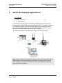
The following illustration shows the type of system you will be setting up.
Note: During the installation, you must connect to the ILX34-AENWG directly via Ethernet to set its
wireless settings so it can communicate with its Access Point. To prevent a loop from occurring,
avoid connecting Ethernet cables to the Access Point and the ILX34-AENWG at the same time
after the wireless link is established.
ProSoft Technology, Inc.
July 31, 2009
Page 13 of 79
ILX34-AENWG ♦ POINT I/O Platform
Wireless Point I/O Adapter
2.1
About the Example Applications
Setup Guide
System Components
We used the following components for the example applications. You need the
same or similar components to set up your own control system using POINT I/O
modules on an EtherNet/IP network.
Quantity
Product Name
Catalog Number
Hardware
1
Wireless Point I/O Adapter
ILX34-AENWG
1
POINT I/O 24V dc sink output module 1734-OV4E/C
1
POINT I/O relay output module
1734-OW2/C
1
DIN rail
199-DR1 or equivalent
1
ControlLogix chassis
1756-A4, (or 1756-A7, 1756-A13,1756-A17)
1
ControlLogix power supply
1756-PA72, (or 1756-PB72)
1
ControlLogix controller
1756-L5* with firmware version 17
1
ControlLogix EtherNet/IP bridge
module
1756-ENBT with firmware version 4.007 or
higher
1
RadioLinx Industrial Hotspot
RLXIB-IHW
1
Personal computer that supports
RSLogix 5000 software
Any appropriate model running Windows NT 4.0,
Service Pack 6A or higher
1
Ethernet switch
Refer to manufacturer's specifications
1
24V dc power supply
Associated media and connectors as needed
Software
1
RSLinx communications software,
version 2.54.00 or later
1
RSLogix 5000 programming software, 9324-RLD300ENE
9355-WAB, 9355-WABOEM, 9355-WABC
version 17 or later
2.2
Set Up the Hardware
In these examples, a ControlLogix chassis contains the Logix controller in slot 0,
and a 1756-ENBT bridge module in slot 3. We mounted the ILX34-AENWG
adapter on a DIN rail in slot 0, with a 1734-OW2/C relay output module in slot 1,
a 1734-OV4E/C sink output module in slot 2, and a 24 volt DC power supply.
To work along with this example, set up your system as follows.
Note that the example application, the Logix controller and 1756-ENBT
module (firmware revision 4.007 or later) uses the slots shown in the
illustration (page 13).
Verify the IP addresses for your programming terminal, 1756-ENBT module,
and ILX34-AENWG adapter.
Verify the position (slot) of the I/O modules on the DIN rail.
Verify that you have properly connected all wiring and cabling.
You must configure your communication driver (such as AB_ETH-1 or ABETHIP-1) in RSLinx software, as described in the User Manual.
Page 14 of 79
ProSoft Technology, Inc.
July 31, 2009
Procedures
Setup Guide
3
ILX34-AENWG ♦ POINT I/O Platform
Wireless Point I/O Adapter
Procedures
In This Chapter
3.1
Install the Configuration Tools ............................................................... 15
Physical Setup....................................................................................... 16
Verify Communication ........................................................................... 55
Install the Configuration Tools
3.1.1 Install the ILX34-AENWG Add-On Profile
1
Verify that your computer meets the hardware and operating system
requirements. (page 10)
Important: You must have "Administrator" rights on your computer to install this application.
2
3
4
5
6
Insert the ProSoft Solutions CD-ROM in an available CD-ROM drive in your
computer.
On most computers, the installation program will start automatically within a
few seconds. If the installation does not start automatically on your computer,
click the START button, choose RUN, and then type explorer. Click OK to start
Windows Explorer. In Windows Explorer, open the MY COMPUTER icon and
navigate to the CD-ROM drive.
Navigate to the folder containing the ILX34-AENWG Add-On Profile, and then
double-click the file SETUP.EXE. This action starts the installation wizard.
Follow the instructions on the installation wizard to install the program.
Click FINISH to complete the installation. If you are prompted to restart your
computer, save your work in any applications that are running, close the
applications, and allow the computer to restart.
ProSoft Technology, Inc.
July 31, 2009
Page 15 of 79
ILX34-AENWG ♦ POINT I/O Platform
Wireless Point I/O Adapter
3.2
Procedures
Setup Guide
Physical Setup
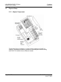
3.2.1 Adapter Components
The Wireless Point I/O Adapter is a communications adapter for POINT I/O
modules. The adapter provides an interface for controlling and communicating
with POINT I/O modules from an Ethernet network.
Page 16 of 79
ProSoft Technology, Inc.
July 31, 2009
Procedures
Setup Guide
ILX34-AENWG ♦ POINT I/O Platform
Wireless Point I/O Adapter
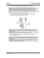
3.2.2 Install the Wireless Point I/O Adapter on the DIN-rail
Warning: You must follow all safety instructions when installing this or any other electronic
devices. Failure to follow safety procedures could result in damage to hardware or data, or even
serious injury or death to personnel. Refer to the documentation for each device you plan to
connect to verify that suitable safety procedures are in place before installing or servicing the
device.
1
2
Position the adapter vertically above the DIN-rail.
Press down firmly to install the adapter on the DIN-rail, and then turn the
orange screw to lock the adaptor onto the DIN-rail.
Warning: If you connect or disconnect the Ethernet cable with power applied to this module or any
device on the network, an electrical arc can occur. This could cause an explosion in hazardous
location installations.
Be sure that power is removed or the area is nonhazardous before proceeding.
3
Slide the safety end cap up to remove. This exposes the backplane and
power interconnections.
Caution: Do not discard the end cap. Use this end cap to cover the exposed interconnections on
the last mounting base on the DIN-rail. Failure to do so could result in equipment damage or injury
from electric shock.
Important: You must use series C POINT I/O modules with the ILX34-AENWG adapter. Series A
or B POINT I/O modules will not work with this adapter.
ProSoft Technology, Inc.
July 31, 2009
Page 17 of 79
ILX34-AENWG ♦ POINT I/O Platform
Wireless Point I/O Adapter
Procedures
Setup Guide
3.2.3 Configure the Wireless Access Point
Although the ILX34-AENWG can communicate with any 802.11b/g Access Point
radio, ProSoft Technology recommends the RadioLinx series Industrial
Broadband radios wherever performance and compatibility are required.
The following configuration steps are for the RLXIB-IHW. Use the examples in
these steps to configure your own Access Point to work with the ILX34-AENWG.
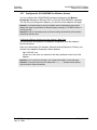
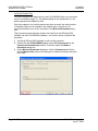
Configure the Master Radio (Required)
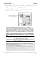
The following illustration shows an example configuration for a RadioLinx
Industrial Hotspot (Access Point) configured as a Master radio.
Note: The radio in this illustration is capable of transmitting at 5 GHz (802.11a) as well as 2.4 GHz
(802.11b/g). The radio in the ILX34-AENWG adapter supports only 2.4 GHz (802.11b/g).
In particular, note the following settings.
Network SSID: All radios on the network must use the same Network SSID
In this example, the Network SSID is "Point_IO".
Channel: All radios must use the same channel. In this example, the channel
is 8 (2447MHz).
Encryption: All radios must use the same encryption settings. In this
example, the encryption type is WPA/WPA2-AES.
Passphrase: All radios must use the same passphrase. For security reasons,
the passphrase field is replaced with asterisks. Make a note of the
passphrase before configuring additional radios.
Important: Take care to enter the passphrase on the ILX34-AENWG exactly as you entered it in
the Master radio.
Page 18 of 79
ProSoft Technology, Inc.
July 31, 2009
Procedures
Setup Guide
ILX34-AENWG ♦ POINT I/O Platform
Wireless Point I/O Adapter
IP Address: The IP address for all radios must be within the same subnet,
and each radio requires its own unique IP address. You can assign static IP
addresses, as in this example, or you can use DHCP (Dynamic Host Control
Protocol) to manage and assign IP addresses automatically.
Note: Refer to the documentation for your radio (for example, the RLXIB-IHW User Manual) for
specific steps to configure the settings in this example.
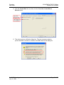
Configure One or More Repeaters (Optional)
The following illustration shows an example configuration for a RadioLinx
Industrial Hotspot (Access Point) configured as a Repeater radio. The need for
repeater radios is determined by the distance between the Master radio and the
ILX34-AENWG, as well as any topographical factors such as hills or other
obstructions, which could prevent a clear line-of-sight signal path.
Note: The radio in this illustration is capable of transmitting at 5 GHz (802.11a) as well as 2.4 GHz
(802.11b/g). The radio in the ILX34-AENWG adapter supports only 2.4 GHz (802.11b/g).
In particular, note the following settings.
Network SSID, Channel, Encryption and Passphrase for the Repeater
radio must match those configured for the Master radio and the ILX34AENWG.
IP Address: The IP address for all radios must be within the same subnet,
and each radio requires its own unique IP address. You can assign static IP
addresses, as in this example, or you can use DHCP (Dynamic Host Control
Protocol) to manage and assign IP addresses automatically.
Note: Refer to the documentation for your radio (for example, the RLXIB-IHW User Manual) for
specific steps to configure the settings in this example.
ProSoft Technology, Inc.
July 31, 2009
Page 19 of 79
ILX34-AENWG ♦ POINT I/O Platform
Wireless Point I/O Adapter
Procedures
Setup Guide
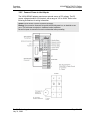
3.2.4 Configure the IP Address with the Thumbwheel Switches
Before you can connect to the ILX34-AENWG for the first time, you must
configure its IP address.
The simplest way to set the IP address for your initial connection is to use the
thumbwheel switches on the front of the adapter.
The three thumbwheel switches represent the final octet for the private IP
address 192.168.1.xxx (where xxx represents the number set on the switches).
The factory default switch setting is 999. Use the buttons above and below each
number to select a temporary IP address to use. Choose a number between 001
and 254, taking care not to duplicate the IP address of any other device on the
network.
If you set the switches to an invalid number (that is, 000 or a value greater than
254), the adapter checks to see if you enabled DHCP, according to the following
table.
If DHCP is
Then the adapter
Enabled
Asks for an address from a DHCP server. The DHCP server also assigns
other Transport Control Protocol (TCP) parameters.
Not enabled
Uses the IP address (along with other TCP configurable parameters)
stored in nonvolatile memory
The updated IP address will take effect when the adapter is powered up.
Important: If you set the thumbwheels on the ILX34-AENWG adapter to the value 888 and then
power cycle the adapter, the following occurs:
The DHCP Enabled function is enabled (set to True).
The Ethernet link is negotiated automatically. The Auto Negotiate function is set to True.
The Web server is enabled.
The password for this page resets to the factory default of "password".
Make a note of the value of the switches before you change them, so you can restore those values
after resetting the adapter.
Page 20 of 79
ProSoft Technology, Inc.
July 31, 2009
Procedures
Setup Guide
ILX34-AENWG ♦ POINT I/O Platform
Wireless Point I/O Adapter
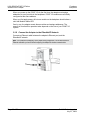
3.2.5 Connect Power to the Adapter
The ILX34-AENWG adapter requires an external source of DC voltage. The DC
source voltage should be 24V nominal, with a range of 10V to 28.8V. Refer to the
following illustrations for wiring information.
Caution: Do not connect 120/240V ac power to this supply.
Warning: If you connect or disconnect wiring while the field-side power is on, an electrical arc can
occur. This could cause an explosion in hazardous location installations.
Be sure that power is removed or the area is nonhazardous before proceeding.
ProSoft Technology, Inc.
July 31, 2009
Page 21 of 79
ILX34-AENWG ♦ POINT I/O Platform
Wireless Point I/O Adapter
Procedures
Setup Guide
When you power up the POINT I/O for the first time, the adapter must assign
addresses to every module in the backplane. POINT I/O modules are all initially
configured at the same address.
When you first apply power, all but one module on the backplane should show a
solid red Module Status LED.
One by one, the adapter resets these modules and assigns addresses. The
amount of time that this operation takes depends on the size of your POINT I/O
system.
3.2.6 Connect the Adapter to the EtherNet/IP Network
Connect an Ethernet cable between the adapter’s Ethernet port, and the
EtherNet/IP network.
Note: This connection is temporary, and is helpful during configuration. You will disconnect the
Ethernet cable after you have finished configuring the adapter for wireless communication.
Page 22 of 79
ProSoft Technology, Inc.
July 31, 2009
Procedures
Setup Guide
ILX34-AENWG ♦ POINT I/O Platform
Wireless Point I/O Adapter
3.2.7 Configure the ILX34-AENWG for Wireless Access
You can configure the ILX34-AENWG's wireless settings from the MODULE
PROPERTIES dialog box in RSLogix 5000, or from the ILX34-AENWG's web page.
The first time you configure the adaptor, you should use the adapter's web page.
Important: The wireless settings for the ILX34-AENWG must be compatible with the Industrial
Hotspot radio (page 18) connected to the Ethernet bridge (for example, a 1756-ENBT module in a
ControlLogix rack).
Important: All radios on the network must use the same settings, otherwise they will be unable to
communicate with each other.
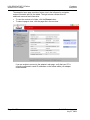
Configuring Wireless Settings from the Adapter's Web Page
You can monitor and update ILX34-AENWG configuration from the adapter's
built-in web server.
Open your web browser (for example, Microsoft Internet Explorer or Firefox), and
connect to the adapter's temporary network address.
http://192.168.1.xxx
(where xxx is the value you entered in the rotary switches on the front of the
adapter.
Important: Your PC must be on the same TCP/IP subnet as the adaptor to view these pages.
Important: You must prefix the numeric IP address with "http://", otherwise the web browser
may not be able to interpret the address.
ProSoft Technology, Inc.
July 31, 2009
Page 23 of 79
ILX34-AENWG ♦ POINT I/O Platform
Wireless Point I/O Adapter
Procedures
Setup Guide
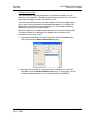
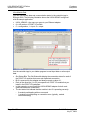
The adapter's home page consists of a tree view in the left pane for navigation,
and an information pane in the middle. The right column contains links for
additional resources and information.
To view the contents of a folder, click the EXPAND button.
To select a page to view, click the page title in the tree view.
If you are unable to connect to the adapter's web page, verify that your PC is
correctly configured to reach IP addresses on the subnet where your adapter
communicates.
Page 24 of 79
ProSoft Technology, Inc.
July 31, 2009
Procedures
Setup Guide
ILX34-AENWG ♦ POINT I/O Platform
Wireless Point I/O Adapter
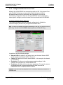
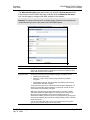
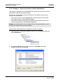
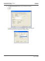
The WIRELESS SETTINGS page opens when you select the CONFIGURATION folder
in the menu on the left side of the page, and then click the WIRELESS SETTINGS
link. Use this page to configure the radio settings for the adapter.
Important: The values on this page are in non-volatile memory. Changes to these parameters do
not take effect until you reset or cycle power to the ILX34-AENWG adapter.
Field
Description
SSID
Assign a network name (SSID) of up to 32 characters. The radio uses this
name in all network references. All radios in a network must have the same
SSID. SSID names are case-sensitive.
Encryption Type
Choose the method by which the adapter will apply encryption security:
NONE (not recommended)
WEP128 - Legacy security setting using a 128-bit key and WEP
encryption.
WPA2/AES (Preferred) - Security setting using WPA (pre-shared key)
authentication and AES encryption.
The preferred encryption type is AES (Advanced Encryption Standard). You
should only select WEP (wired equivalency protocol) for use with an older
client radio that only has WEP encryption.
WEP is the original security protocol used by 802.11 networks, but AES
offers better protection against attacks, for several reasons: AES uses an
advanced encryption algorithm that is not susceptible to the same
weaknesses as WEP, it performs dynamic key management by changing the
session keys frequently, and it performs message integrity checks to prevent
forgery and replay.
You can also select WEP 128, or None (no encryption) as the encryption
type, but none of these settings are recommended.
ProSoft Technology, Inc.
July 31, 2009
Page 25 of 79
ILX34-AENWG ♦ POINT I/O Platform
Wireless Point I/O Adapter
Procedures
Setup Guide
Field
Description
WPA Passphrase
To use WPA2/AES encryption on packets sent between the radios, enter a
WPA2/AES pass phrase of between eight and 63 normal keyboard
characters. This phrase automatically generates an encryption key of 128
hexadecimal characters. This field is only available if you select WPA2/AES
as the encryption type.
WEP Key Index
If using WEP128 encryption, select the Key Index that matches the Key Index
used in the Access Point.
WEP Keys (1-4)
If using WEP128 encryption, enter the WEP Keys that match the Keys in the
Access Point.
Transmit Data
Rate
The recommended The ILX34-AENWG supports the following transmit data
rates. The default value is Auto: Max 54 Mbps, and this is the recommended
value for most applications.
1 Mbps
Auto: Max. 1 Mbps
2 Mbps
Auto: Max. 2 Mbps
5.5 Mbps
Auto: Max. 5.5 Mbps
11 Mbps
Auto: Max. 11 Mbps
18 Mbps
Auto: Max. 18 Mbps
24 Mbps
Auto: Max. 24 Mbps
36 Mbps
Auto: Max. 36 Mbps
54 Mbps
Auto: Max. 54 Mbps
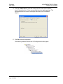
Verify Wireless Communication
At this point, with the Ethernet cable still attached to the ILX34-AENWG, go to
the WIRELESS STATISTICS web page, and verify that the ILX34-AENWG is linked
to the Access Point.
After the link is established, you should disconnect the Ethernet cable from the
ILX34 and reconnect it to the Access Point. From this point on, all
communications can be done wirelessly.
Note: If Ethernet cables are connected to both the ILX34-AENWG and the Access Point, and there
is a wireless link between these devices, a loop will be formed. Typically the Access Point detects
this loop and disconnects the wireless link. In this condition, the link LED on the ILX34-AENWG will
periodically come on and then go off. Also, the Wireless Statistics web page will sometimes show
the unit is linked and then later show that it is not.
Page 26 of 79
ProSoft Technology, Inc.
July 31, 2009
Procedures
Setup Guide
ILX34-AENWG ♦ POINT I/O Platform
Wireless Point I/O Adapter
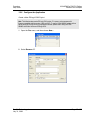
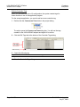
3.2.8 Configure the Application
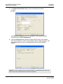
Create a New RSLogix 5000 Project
Note: The following steps require RSLogix 5000 version 17 or newer, and a processor with
firmware compatible with this version of RSLogix 5000. To use the ILX34-AENWG adapter with an
earlier version of RSLogix 5000 or the processor firmware, please refer to Using the ILX34AENWG with Earlier Versions of RSLogix 5000.
1
Open the FILE menu, and then choose NEW…
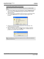
2
Select REVISION 17.
ProSoft Technology, Inc.
July 31, 2009
Page 27 of 79
ILX34-AENWG ♦ POINT I/O Platform
Wireless Point I/O Adapter
Procedures
Setup Guide
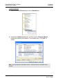
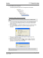
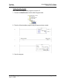
Create the Network
1
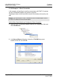
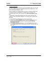
Right-click I/O CONFIGURATION and choose NEW MODULE…
2
Expand the COMMUNICATIONS node, and then select the ETHERNET BRIDGE
module that matches your hardware. This example uses a 1756-ENBT/A
module.
Note: If you are prompted to "Select Major Revision", choose the lower of the available revision
numbers.
Page 28 of 79
ProSoft Technology, Inc.
July 31, 2009
Procedures
Setup Guide
ILX34-AENWG ♦ POINT I/O Platform
Wireless Point I/O Adapter
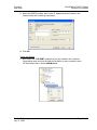
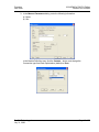
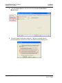
3
Name the ENBT/A module, then set the IP Address and slot location in the
local rack with the ControlLogix processor.
4
Click OK.
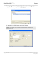
Create the Adapter
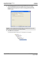
1
Next, select the 1756-ENBT module that you just created in the Controller
Organization pane and click the right mouse button to open a shortcut menu.
On the shortcut menu, choose NEW MODULE.
ProSoft Technology, Inc.
July 31, 2009
Page 29 of 79
ILX34-AENWG ♦ POINT I/O Platform
Wireless Point I/O Adapter
Procedures
Setup Guide
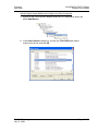
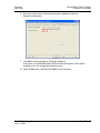
2
In the SELECT MODULE dialog box, click the VENDOR tab, and then expand the
PROSOFT TECHNOLOGY node. Click the BY VENDOR tab, expand the PROSOFT
TECHNOLOGY node, and then select ILX34-AENWG.
3
Name the ILX34-AENWG adapter, and set the IP address.
Important: The IP address on the ILX34-AENWG's thumbwheel switches must match the IP
address you enter here.
Page 30 of 79
ProSoft Technology, Inc.
July 31, 2009
Procedures
Setup Guide
ILX34-AENWG ♦ POINT I/O Platform
Wireless Point I/O Adapter
Configure Chassis Size
The ILX34-AENWG requires configuration of its chassis size before you can
make any I/O connections. The default setting for the chassis size is 1 slot, which
represents the adapter by itself, and allows for no I/O.
You must set the chassis size to a number equaling 1 slot for the adapter plus 1
slot for each I/O module present in the adapter's backplane. For example, the
adapter plus 2 I/O modules uses a chassis size of 3. The adapter stores this
chassis size setting in non-volatile storage.
When the adapter's non-volatile chassis size does not match the actual number
of modules present on its backplane, the adapter does not make any I/O
connections and an error occurs.
1
In the Module Definition area of the General tab, click the CHANGE button.
This action opens the MODULE DEFINITION dialog box.
2
Select the Chassis Size for your project from the dropdown list, and then
Click OK to close the MODULE DEFINITION dialog box. In a later step, you will
verify the chassis size when you are online with the ILX34-AENWG.
ProSoft Technology, Inc.
July 31, 2009
Page 31 of 79
ILX34-AENWG ♦ POINT I/O Platform
Wireless Point I/O Adapter
Procedures
Setup Guide
3.2.9 Example 1 - Direct Connection and Rack Optimization
This example configures your ILX34-AENWG for both direct connection and rack
optimization using RSLogix 5000 software.
You can mix communication formats for different I/O modules communicating
through the same adapter.
I/O modules set up to use rack optimization communicate at the rate of the
RPI configured for the ILX34-AENWG adapter.
I/O modules configured for direct communication communicate at their own
set RPI and ignore the ILX34-AENWG adapter RPI.
Attention: You must use series C POINT I/O modules with the ILX34-AENWG adapter. Series A
or B POINT I/O modules will not work with this adapter.
Add the Relay Output Module and Configure for Direct Connection
1
Right-click the ILX34-AENWG adapter under the I/O Configuration folder and
select NEW MODULE.
2
In the SELECT MODULE dialog box, choose the 1734-OW2 relay output
module from the list, and click OK.
Page 32 of 79
ProSoft Technology, Inc.
July 31, 2009
Procedures
Setup Guide
3
ILX34-AENWG ♦ POINT I/O Platform
Wireless Point I/O Adapter
In the MODULE PROPERTIES dialog, enter the following information:
a) Name
b) Slot
In the Module Definition area, click the CHANGE ... button, and change the
Connection type from Rack Optimization (default) to DATA.
ProSoft Technology, Inc.
July 31, 2009
Page 33 of 79
ILX34-AENWG ♦ POINT I/O Platform
Wireless Point I/O Adapter
4
Procedures
Setup Guide
Click the CONNECTION tab, and then change the RPI value for the module
from 20 (the default) to 50 (the recommended value for analog or specialty
modules). This value determines how often to exchange data with the ILX34AENWG adapter.
Important: To avoid overloading the ILX34-AENWG adapter, we recommend that RPI be no less
than 10 ms for rack connections and 50 ms for direct connections.
5
Click OK save the configuration.
The following illustration shows the I/O Configuration for this project.
Page 34 of 79
ProSoft Technology, Inc.
July 31, 2009
Procedures
Setup Guide
ILX34-AENWG ♦ POINT I/O Platform
Wireless Point I/O Adapter
Add the Digital Output Module and Configure for Rack Optimization
1
Right-click the ILX34-AENWG adapter under the I/O Configuration folder and
select NEW MODULE.
2
In the SELECT MODULE dialog box, choose the 1734-OV4E digital output
module from the list, and click OK.
ProSoft Technology, Inc.
July 31, 2009
Page 35 of 79
ILX34-AENWG ♦ POINT I/O Platform
Wireless Point I/O Adapter
3
Procedures
Setup Guide
In the MODULE PROPERTIES dialog, enter the following information:
a) Name
b) Slot
In the MODULE DEFINITION area of the dialog box, notice that the default
Connection type is RACK OPTIMIZATION.
4
Click the CONNECTION tab, and then change the RPI value for the module
from 20 (the default) to 10 (the recommended value for digital modules). This
value determines how often to exchange data with the ILX34-AENWG
adapter.
Important: To avoid overloading the ILX34-AENWG adapter, we recommend that RPI be no less
than 10 ms for rack connections and 50 ms for direct connections.
Page 36 of 79
ProSoft Technology, Inc.
July 31, 2009
Procedures
Setup Guide
5
ILX34-AENWG ♦ POINT I/O Platform
Wireless Point I/O Adapter
Click OK save the configuration.
The following illustration shows the I/O Configuration for this project.
Download the Sample Program to the Processor
Note: The key switch on the front of the ControlLogix processor must be in the REM or PROG
position.
1
2
3
4
If you are not already online with the processor, open the COMMUNICATIONS
menu, and then choose DOWNLOAD. RSLogix will establish communication
with the processor.
When communication is established, RSLogix will open a confirmation dialog
box. Click the DOWNLOAD button to transfer the sample program to the
processor.
RSLogix will compile the program and transfer it to the processor. This
process may take a few minutes.
When the download is complete, RSLogix will open another confirmation
dialog box. If the keyswitch is in the REM position, click OK to switch the
processor from Program mode to Run mode.
Note: If you receive an error message during these steps, refer to your RSLogix documentation to
interpret and correct the error.
ProSoft Technology, Inc.
July 31, 2009
Page 37 of 79
ILX34-AENWG ♦ POINT I/O Platform
Wireless Point I/O Adapter
Procedures
Setup Guide
Verify the Chassis Size
You must configure the chassis size for the ILX34-AENWG before you can make
any I/O connections (page 31). The default setting for the chassis size is 1 slot,
which represents the adapter by itself.
When the adapter's non-volatile chassis size does not match the actual number
of modules present on its backplane, the adapter does not make any I/O
connections and an error occurs, as shown in the MODULE PROPERTIES dialog
box.
This procedure synchronizes the chassis size value from the RSLogix 5000
software into the ILX34-AENWG hardware. You must be online to perform this
procedure.
1
2
3
Verify that RSLogix 5000 software is online to the processor.
Double-click the ILX34-AENWG adapter under I/O CONFIGURATION in the
CONTROLLER ORGANIZATION window. This action opens the MODULE
PROPERTIES dialog box.
On the MODULE PROPERTIES dialog box, click the CONNECTION tab. Notice
that the MODULE FAULT area of the dialog box contains information about the
error code.
Page 38 of 79
ProSoft Technology, Inc.
July 31, 2009
Procedures
Setup Guide
ILX34-AENWG ♦ POINT I/O Platform
Wireless Point I/O Adapter
4
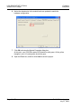
Click the CHASSIS SIZE tab, and then click the CLICK SET CHASSIS SIZE IN
MODULE button.
5
This action opens a notification dialog box. Take any necessary steps to
prevent hazardous conditions, and then click OK to dismiss the dialog box.
ProSoft Technology, Inc.
July 31, 2009
Page 39 of 79
ILX34-AENWG ♦ POINT I/O Platform
Wireless Point I/O Adapter
Procedures
Setup Guide
6
Notice the chassis size in the module has been updated to match the
hardware configuration.
7
Click OK to dismiss the Module Properties dialog box.
At this point, your POINTBus status LED should be solid green. All the yellow
triangles in your I/O configuration should be gone.
8
Open the FILE menu, and then click SAVE to save the project.
Page 40 of 79
ProSoft Technology, Inc.
July 31, 2009
Procedures
Setup Guide
ILX34-AENWG ♦ POINT I/O Platform
Wireless Point I/O Adapter
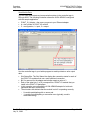
View Module Data
You can view module data and communication status in the controller tags in
RSLogix 5000. The following illustration shows the ILX34-AENWG configured
with the sample application.
POINT_IO_Adapter = the name you gave to your Ethernet adapter
# = slot number of POINT I/O module
C = configuration, I = input, O = output
Use the controller tags in your ladder program to read input data or write output
data.
Slot Status Bits: The Slot Status bits display the connection status for each of
the POINT I/O modules that use a rack-optimized connection.
Bit 0 is reserved for the adapter and always reports a value of 1.
Each of the other bits (1 to 63) correspond to a POINT I/O module that you
install in the POINT I/O backplane.
In this example, we configured the ILX34-AENWG adapter for both rackoptimized and direct connections.
The slot status bits indicate that the module in slot 2 is operating correctly:
o 0=module participating with no errors and
o 1=module not participating or connection error (typically, module
removed/missing)
ProSoft Technology, Inc.
July 31, 2009
Page 41 of 79
ILX34-AENWG ♦ POINT I/O Platform
Wireless Point I/O Adapter
Procedures
Setup Guide
3.2.10 Example 2 - Direct Connection
In this example, a ControlLogix controller communicates with POINT I/O modules
via the ILX34-AENWG adapter using a direct connection.
The adapter makes a direct connection to each of the modules referenced by the
data.
Attention: You must use series C POINT I/O modules with the ILX34-AENWG adapter. Series A
or B POINT I/O modules will not work with this adapter.
Add the Relay Output Module and Configure for Direct Connection
1
Right-click the ILX34-AENWG adapter under the I/O Configuration folder and
select NEW MODULE.
2
In the SELECT MODULE dialog box, choose the 1734-OW2 relay output
module from the list, and click OK.
Page 42 of 79
ProSoft Technology, Inc.
July 31, 2009
Procedures
Setup Guide
3
ILX34-AENWG ♦ POINT I/O Platform
Wireless Point I/O Adapter
In the MODULE PROPERTIES dialog, enter the following information:
a) Name
b) Slot
In the Module Definition area, click the CHANGE ... button, and change the
Connection type from Rack Optimization (default) to DATA.
ProSoft Technology, Inc.
July 31, 2009
Page 43 of 79
ILX34-AENWG ♦ POINT I/O Platform
Wireless Point I/O Adapter
4
Procedures
Setup Guide
Click the CONNECTION tab, and then change the RPI value for the module
from 20 (the default) to 50 (the recommended value for analog or specialty
modules). This value determines how often to exchange data with the ILX34AENWG adapter.
Important: To avoid overloading the ILX34-AENWG adapter, we recommend that RPI be no less
than 10 ms for rack connections and 50 ms for direct connections.
5
Click OK save the configuration.
The following illustration shows the I/O Configuration for this project.
Page 44 of 79
ProSoft Technology, Inc.
July 31, 2009
Procedures
Setup Guide
ILX34-AENWG ♦ POINT I/O Platform
Wireless Point I/O Adapter
Add the Digital Output Module and Configure for Direct Connection
1
Right-click the ILX34-AENWG adapter under the I/O Configuration folder and
select NEW MODULE.
2
In the SELECT MODULE dialog box, choose the 1734-OV4E digital output
module from the list, and click OK.
ProSoft Technology, Inc.
July 31, 2009
Page 45 of 79
ILX34-AENWG ♦ POINT I/O Platform
Wireless Point I/O Adapter
3
Procedures
Setup Guide
In the MODULE PROPERTIES dialog, enter the following information:
a) Name
b) Slot
In the Module Definition area, click the CHANGE ... button, and change the
Connection type from Rack Optimization (default) to DATA.
Page 46 of 79
ProSoft Technology, Inc.
July 31, 2009
Procedures
Setup Guide
ILX34-AENWG ♦ POINT I/O Platform
Wireless Point I/O Adapter
4
Click the CONNECTION tab, and then change the RPI value for the module
from 20 (the default) to 10 (the recommended value for digital modules). This
value determines how often to exchange data with the ILX34-AENWG
adapter.
5
Click OK save the configuration.
The following illustration shows the I/O Configuration for this project.
ProSoft Technology, Inc.
July 31, 2009
Page 47 of 79
ILX34-AENWG ♦ POINT I/O Platform
Wireless Point I/O Adapter
Procedures
Setup Guide
Edit the Controller Tags
When you add modules to the I/O configuration, the system creates tags for
those modules to use in the application program.
For the example application, you need to add one more controller tag.
1
Double-click the CONTROLLER TAGS folder in the project dialog.
The action opens the CONTROLLER TAGS dialog box. You will see the tags
created for the ILX34-AENWG adapter and digital I/O modules.
2
Click the Edit Tags tab at the bottom of the Controller Tags dialog.
3
Create the following tag:
Tag
Type
Parts_Count
Counter
4
Close the Controller Tags dialog.
Page 48 of 79
ProSoft Technology, Inc.
July 31, 2009
Procedures
Setup Guide
ILX34-AENWG ♦ POINT I/O Platform
Wireless Point I/O Adapter
Create the Ladder Program
Next, create the example ladder program to test the I/O.
1
Double-click MAIN ROUTINE under the Main Program folder.
2
Enter the following ladder program using the tags previously created.
3
Save the program.
ProSoft Technology, Inc.
July 31, 2009
Page 49 of 79
ILX34-AENWG ♦ POINT I/O Platform
Wireless Point I/O Adapter
Procedures
Setup Guide
Download the Sample Program to the Processor
Note: The key switch on the front of the ControlLogix processor must be in the REM or PROG
position.
1
2
3
4
If you are not already online with the processor, open the COMMUNICATIONS
menu, and then choose DOWNLOAD. RSLogix will establish communication
with the processor.
When communication is established, RSLogix will open a confirmation dialog
box. Click the DOWNLOAD button to transfer the sample program to the
processor.
RSLogix will compile the program and transfer it to the processor. This
process may take a few minutes.
When the download is complete, RSLogix will open another confirmation
dialog box. If the keyswitch is in the REM position, click OK to switch the
processor from Program mode to Run mode.
Note: If you receive an error message during these steps, refer to your RSLogix documentation to
interpret and correct the error.
Page 50 of 79
ProSoft Technology, Inc.
July 31, 2009
Procedures
Setup Guide
ILX34-AENWG ♦ POINT I/O Platform
Wireless Point I/O Adapter
Verify the Chassis Size
You must configure the chassis size for the ILX34-AENWG before you can make
any I/O connections (page 31). The default setting for the chassis size is 1 slot,
which represents the adapter by itself.
When the adapter's non-volatile chassis size does not match the actual number
of modules present on its backplane, the adapter does not make any I/O
connections and an error occurs, as shown in the MODULE PROPERTIES dialog
box.
This procedure synchronizes the chassis size value from the RSLogix 5000
software into the ILX34-AENWG hardware. You must be online to perform this
procedure.
1
2
3
Verify that RSLogix 5000 software is online to the processor.
Double-click the ILX34-AENWG adapter under I/O CONFIGURATION in the
CONTROLLER ORGANIZATION window. This action opens the MODULE
PROPERTIES dialog box.
On the MODULE PROPERTIES dialog box, click the CONNECTION tab. Notice
that the MODULE FAULT area of the dialog box contains information about the
error code.
ProSoft Technology, Inc.
July 31, 2009
Page 51 of 79
ILX34-AENWG ♦ POINT I/O Platform
Wireless Point I/O Adapter
Procedures
Setup Guide
4
Click the CHASSIS SIZE tab, and then click the CLICK SET CHASSIS SIZE IN
MODULE button.
5
This action opens a notification dialog box. Take any necessary steps to
prevent hazardous conditions, and then click OK to dismiss the dialog box.
Page 52 of 79
ProSoft Technology, Inc.
July 31, 2009
Procedures
Setup Guide
ILX34-AENWG ♦ POINT I/O Platform
Wireless Point I/O Adapter
6
Notice the chassis size in the module has been updated to match the
hardware configuration.
7
Click OK to dismiss the Module Properties dialog box.
At this point, your POINTBus status LED should be solid green. All the yellow
triangles in your I/O configuration should be gone.
8
Open the FILE menu, and then click SAVE to save the project.
ProSoft Technology, Inc.
July 31, 2009
Page 53 of 79
ILX34-AENWG ♦ POINT I/O Platform
Wireless Point I/O Adapter
Procedures
Setup Guide
View Module Data
You can view module data and communication status in the controller tags in
RSLogix 5000. The following illustration shows the ILX34-AENWG configured
with the sample application.
ILX34_AENWG = the name you gave to your Ethernet adapter
# = slot number of POINT I/O module
C = configuration, I = input, O = output
Use the controller tags in your ladder program to read input data or write output
data.
Slot Status Bits: The Slot Status bits display the connection status for each of
the POINT I/O modules that use a rack-optimized connection.
Bit 0 is reserved for the adapter and always reports a value of 1.
Each of the other bits (1 to 63) correspond to a POINT I/O module that you
install in the POINT I/O backplane.
In this example, we configured the ILX34-AENWG adapter for both rackoptimized and direct connections.
The slot status bits indicate that the module in slot 2 is operating correctly:
o 0=module participating with no errors and
o 1=module not participating or connection error (typically, module
removed/missing)
Page 54 of 79
ProSoft Technology, Inc.
July 31, 2009
Procedures
Setup Guide
3.3
ILX34-AENWG ♦ POINT I/O Platform
Wireless Point I/O Adapter
Verify Communication
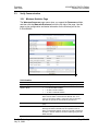
3.3.1 Wireless Statistics Page
The WIRELESS STATISTICS page opens when you expand the DIAGNOSTICS folder,
and then click the WIRELESS STATISTICS link on the left side of the page. Use this
page to view configuration and status information for the Wireless port on the
ILX34-AENWG.
Link Information
Field
Description
Signal Strength
The colored graph indicates the signal level (page 56).
Signal to Noise
< 0 , this is a BAD condition
< 10, this is an OK condition
> 10, this is a GOOD condition
Radio Link Time
The up-link time in days:hours:minutes:seconds.
Note: This link status is checked at the Refresh rate, once
every 10 seconds by default. If the link is down for less time
than this, the up-time for the link will not get reset to 0.
Radio Parent MAC
The MAC address (hexadecimal) of the parent radio (access
point)
Data Rate
Rf rate of the last packet received by the ILX34-AENWG.
Although this field is informational, some packets, such as
802.11 management packets, will be at a rate that is lower than
the data. In such an instance, the data could be going at a rate
faster than this.
ProSoft Technology, Inc.
July 31, 2009
Page 55 of 79
ILX34-AENWG ♦ POINT I/O Platform
Wireless Point I/O Adapter
Procedures
Setup Guide
Statistics
Field
Description
Packets Received Successfully
Messages received with success. The average value gives a
good indication of RF bandwidth consumption. The average
should not exceed 1000 packets per second. If it does exceed
this, the RPI should be decreased on the connections.
Packets Transmitted
Successfully
Messages sent with success. The average value gives a good
indication of RF bandwidth consumption. The average should
not exceed 500 packets per second. f it does exceed this, the
RPI should be decreased on the connections.
Packet Transmit Failures
Messages that have been retried 8 times and still were not
transferred successfully. This number should not exceed 1% of
the Packets Transmitted successfully.
Packet Transmit Retries
Messages sent requiring a retry. Retries of 20 to 50 per second
are not uncommon. Retries of several hundred per second
indicate the RF network is too busy or the RF link is poor.
Version
Field
Description
Kernel Revision
The internal software revision for the POINT I/O adapter
WIFI Module Firmware
The internal software revision for the wireless component of the
POINT I/O adapter
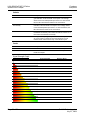
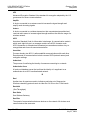
Signal Strength Graph
Image
Page 56 of 79
Signal Strength
-90 dBm
Signal to Noise
0 dB
-88 dBm
2 dB
-86 dBm
4 dB
-84 dBm
6 dB
-82 dBm
8 dB
-80 dBm
10 dB
-78 dBm
12 dB
-76 dBm
14 dB
-74 dBm
16 dB
-72 dBm
18 dB
-70 dBm
20 dB
-68 dBm
22 dB
-66 dBm
24 dB
-64 dBm
26 dB
-62 dBm
28 dB
-60 dBm
30 dB
ProSoft Technology, Inc.
July 31, 2009
Conclusion
Setup Guide
4
ILX34-AENWG ♦ POINT I/O Platform
Wireless Point I/O Adapter
Conclusion
In This Chapter
4.1
How to Get Help .................................................................................... 57
Frequently Asked Questions ................................................................. 58
How to Get Help
ProSoft Technology has several ways for customers to acquire knowledge fast!
In an all encompassing support page, technical support is now right at your
fingertips. Here you get the ProSoft Knowledgebase, a community of experts and
experienced end-users on our bulletin board, as well as presentations, one-onone chat, on the go tutorials and streaming media training.
Knowledgebase: Type a question into our knowledgebase search engine.
Answers come from a technical support knowledge database built from helping
inquisitive customers like you.
Frequently Asked Questions: If you want to know ProSoft Support’s top ten
questions asked, just click on our FAQ. Using an FAQ could get you the answers
you need immediately. Check back regularly for updates.
Bulletin Board: Here’s a public forum just for you. Make comments, ask
questions, and get to know ProSoft’s automation community. Register, login, and
join the discussion.
Live Chat (8am to 5pm PST): Communicate with a Technical Support Engineer
online. This is just one more way to get one-on-one support from our
knowledgeable support staff.
Downloads: Look no further. Get manuals, datasheets, configuration utilities,
and more.
Training: Get help through our online tutorials and streaming media training
series.
Contact: You can always call or email with your technical support questions.
Also, if you have any comments or suggestions, please let us know.
Go to www.prosoft-technology.com/support (http://www.prosofttechnology.com/support) or call +1.661.716.5100
ProSoft Technology, Inc.
July 31, 2009
Page 57 of 79
ILX34-AENWG ♦ POINT I/O Platform
Wireless Point I/O Adapter
4.2
Conclusion
Setup Guide
Frequently Asked Questions
What is the benefit of using ProSoft's RadioLinx Industrial Hotspots vs. third party WLAN
access points (APs)?
ProSoft Technology's Industrial Hotspots (RLXIB-IHW and RLXIB-IHG) have
been optimized for use with multicast I/O messaging with integrated RF based
IGMP querying to learn locations of data consumers and efficiently route traffic to
them, saving bandwidth vs. third-party Access Points that would simply
broadcast the produced message. In addition, ProSoft Technology's Industrial
Hotspots take advantage of the learned consumer locations to unicast the
wireless packets, enabling retransmission and fewer dropped data packets.
What is ProSoft Technology's Integrated Wireless Architecture™?
ProSoft Technology's Integrated Wireless Architecture (IWA) refers to the high
level of optimization of ProSoft Technology's industrial wireless LAN products for
use with Rockwell Automation's Integrated Architecture. Examples include
superior handling of multicast producer consumer messaging, use of wireless
CIP diagnostic objects, integration of wireless into Rockwell Automation's POINT
I/O and ControlLogix® platforms, and using AOPs for RSLogix™ 5000 to
configure and monitor ProSoft Technology IWA devices. ProSoft Technology's
RadioLinx® Industrial Hotspots provide the IWA infrastructure for chassis-based
products like the wireless POINT I/O Adapter (ILX34-AENWG).
Will the ILX34-AENWG communicate with ProSoft Technology's wireless module for
ControlLogix (MVI56-WA-EIP)?
The MVI56-WA-EIP module does not support implicit messaging and so does not
support the ILX34-AENWG. Instead, use a RadioLinx Industrial Hotspot™ such
as RLXIB-IHG or RLXIB-IHW connected to an ENET card or CompactLogix™
Ethernet processor.
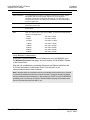
What are the minimum firmware and software requirements of my Rockwell Automation®
Logix controllers and RSLogix software required to configure the ILX34-AENWG using
RSLogix 5000?
Product
Version
RSLogix 5000
v17
RSLinx
v2.54
1756-EN2T
v2.005
1756-ENBT
v4.007
1756-ENET Ser B
v2.7
1756-L6x
v17.03
1756-6xS (Safety PLC)
v17.07
1768-ENBT
v2.003
1769-L32E
v17.04
1769-L35E
v17.04
Page 58 of 79
ProSoft Technology, Inc.
July 31, 2009
Conclusion
Setup Guide
ILX34-AENWG ♦ POINT I/O Platform
Wireless Point I/O Adapter
If I do not have the minimum versions list above, can I still use the ILX34-AENWG?
Yes. Configure wireless parameters using the integrated web pages in the ILX34AENWG. Configure the I/O modules using the 1734-AENT Add-On Profile.
Can I use the ILX34-AENWG in safety applications? If so, why is it not red like other safety
products? What safety level is available?
Rockwell Automation makes safety I/O modules for the POINT I/O platform
called POINT Guard I/O™. The safety functionality is in the devices, in this case
a GuardLogix™ controller and POINT Guard I/O modules, and it makes no
difference whether the connection is wired or wireless provided supported RPI
times meet requirements and long enough that nuisance safety trips are avoided.
1734-IB8S - 8 Point Safety Sink Input and 1734-OB8S - 8 Point Safety Source
Output are the two POINT Guard I/O modules available today. The ILX34AENWG passes data through to the POINT Guard I/O modules and thus does
not require safety rating and is not red. TÜV Functional safety rated: up to SIL 3,
Category 4, performance Level e.
How many ILX34-AENWGs can I use in one network?
There are two limitations to the number of ILX34-AENWGs that may be used in a
single network - the number of connections supported by the Rockwell
Automation® controller or ENET card and the practical limitation of how long the
RPI needs to be to support the required number of connections. For example, the
1756-ENBT and 1756-EN2T Ethernet communications modules support 128 and
256 connections, respectively. If additional connections are required, additional
ENET cards may be used. Rack optimization of discrete I/O helps to minimize
the number of connections. From a RPI perspective, each connection will
increase the minimum RPI time and at some point the RPI may exceed the
maximum allowed by the application. If the RPI is too long, the ILX34-AENWG
network may be segmented using multiple access points operating on nonoverlapping channels.
What if my application requires standalone control or faster sense to actuation time than
supported by the minimum RPI time of the ILX34-AENWG (<20 msec)?
Use the DeviceLogix POINT I/O module - 1734-8CFGDLX that can execute
"locally" and autonomously up to 124 function blocks or ladder logic.
What diagnostic information is available from the ILX34-AENWG?
Wireless performance statistics may be accesses from the web pages of the
ILX34-AENWG, the RSLogix™ 5000 Add-On Profile, or in a HMI software such
as FactoryTalk® View using the wireless diagnostic object. Parameters include:
firmware number, link time, parent MAC address, parent data rate, average
signal level, average noise level, transmit packet successes and failures, receive
packet successes and failures, and number of transmit retries.
ProSoft Technology, Inc.
July 31, 2009
Page 59 of 79
ILX34-AENWG ♦ POINT I/O Platform
Wireless Point I/O Adapter
Page 60 of 79
Conclusion
Setup Guide
ProSoft Technology, Inc.
July 31, 2009
Glossary of Terms
Setup Guide
5
ILX34-AENWG ♦ POINT I/O Platform
Wireless Point I/O Adapter
Glossary of Terms
8
802.11
A group of wireless specifications developed by the IEEE. It details a wireless
interface between devices to manage packet traffic.
802.11a
Operates in the 5 GHz frequency range with a maximum 54 Mbit/sec signaling
rate.
802.11b
Operates in the 2.4 GHz Industrial, Scientific, and Measurement (ISM) band.
Provides signaling rates of up to 11 Mbit/sec and is the most commonly used
frequency.
802.11g
Similar to 802.11b but supports signaling rates of up to 54 Mbit/sec. Operates in
the heavily used 2.4 GHz ISM band but uses a different radio technology to boost
throughput.
802.11i
Sometimes Wi-Fi Protected Access 2 (WPA 2). WPA 2 supports the 128-bit and
above advanced encryption Standard, along with 802.1x authentication and key
management features.
802.11n
Designed to raise effective WLAN throughput to more than 100 Mbit/sec.
802.11s
Deals with mesh networking.
A
Access Point
A generic term for an 802.11 radio that "attaches" other 802.11 radios (clients) to
a wired network. APs can also bridge to one another.
Ad hoc Mode
Wireless network framework in which devices can communicate directly with one
another without using an AP or a connection to a regular network.
ProSoft Technology, Inc.
July 31, 2009
Page 61 of 79
ILX34-AENWG ♦ POINT I/O Platform
Wireless Point I/O Adapter
Glossary of Terms
Setup Guide
AES
Advanced Encryption Standard. New standard for encryption adopted by the U.S.
government for secure communications.
Amplifier
A device connected to an antenna used to increase the signal strength and
amplify weak incoming signals.
Antenna
A device connected to a wireless transceiver that concentrates transmitted and
received radio waves to increase signal strength and thus the effective range of a
wireless network.
ASCII
American Standard Code for Information Interchange. A communication mode in
which each eight-bit byte in a message contains one ASCII character code.
ASCII characters (or hexadecimal characters) are sometimes used as a key to
encrypt data and ensure its secure transmission.
Association
Process whereby two 802.11 radios establish communications with each other.
Requirements for communication include common SSID (network names) and
encryption settings.
Authenticate
The process of confirming the identity of someone connecting to a network.
Authentication Server
A back-end database server that confirms the identity of a supplicant to an
authenticator in an 802.1x-authenticated network.
B
Band
Another term for spectrum used to indicate a particular set of frequencies.
Wireless networking protocols work in either the 2.4 GHz or the 5 GHz bands.
Bandwidth
(See Throughput)
Base Station
See Wireless Gateway
Baud Rate
The speed of communication between devices on the network. All devices must
communicate at the same rate.
Page 62 of 79
ProSoft Technology, Inc.
July 31, 2009
Glossary of Terms
Setup Guide
ILX34-AENWG ♦ POINT I/O Platform
Wireless Point I/O Adapter
BootP
BootP (Bootstrap Protocol) is a low-level protocol that provides configurations to
other nodes on a TCP/IP network. BootP configuration files let you automatically
assign IP addresses to an Ethernet module (you can also obtain subnet masks
and gateway addresses from BootP).
bps
Bits per Second. A measure of data transmission speed across a network or
communications channel;bps is the number of bits that can be sent or received
per second.
Bridge
A node between two similar communication subnets where protocol translation is
minimal.
C
Channel
One portion of the available radio spectrum that all devices on a wireless network
use to communicate. Changing the channel on the access point/router can help
reduce interference.
CIP
Control and information protocol, the EtherNet/IP application layer uses the
producer/consumer networking model. In this model one producer broadcasts
(multicasts) the data once to all the consumers. All consumers see the data
simultaneously and may choose whether to consume (receive) the data or not.
Delivery time is consistent, no matter how many consumers there are.
Client
A client is software program, or the device on which that program runs, that
makes requests for information from a software program, or the device on which
that program runs, in a client-server relationship.
A Client on an Ethernet network is equivalent to a Master on a serial network.
Configuration PC
A Computer that contains the configuration tools for the ILX34-AENWG.
Connection
The communication mechanism from the controller to another module in the
control system, usually used to exchange I/O data.
consumer
A destination device in the CIP networking model. See CIP.
ProSoft Technology, Inc.
July 31, 2009
Page 63 of 79
ILX34-AENWG ♦ POINT I/O Platform
Wireless Point I/O Adapter
Glossary of Terms
Setup Guide
CSMA/CD
Carrier sense multiple access/collision detection is the access method used in
Ethernet. When a device wants to gain access to the network, it checks to see if
the network is quiet (senses the carrier). If it is not, it waits a random amount of
time before retrying. If the network is quiet and two devices access the line at
exactly the same time, their signals collide. When the collision is detected, they
both back off and each waits a random amount of time before retrying.
D
dBi
Decibels referenced to an "ideal" isotropic radiator in free space; frequently used
to express antenna gain
dBm
Decibels referenced to one milliwatt (mW); an "absolute" unit used to measure
signal power (transmit power output or received signal strength)
DCE
Data communications equipment. A modem, for example.
Decibel (dB)
A measure of the ratio between two signal levels; used to express gain (or loss)
in a system.
Default Gateway
The IP address of a network router where data is sent if the destination IP
address is outside the local subnet. The gateway is the device that routes the
traffic from the local area network to other networks such as the Internet.
Determinism
The ability to predict when information will be delivered. Important in time-critical
applications.
DHCP
The dynamic host configuration protocol is an Internet protocol, similar to BootP,
for automating the configuration of computers that use TCP/IP. DHCP can be
used to automatically assign IP addresses, to deliver IP stack configuration
parameters, such as the subnet mask and default router, and to provide other
configuration information, such as the addresses for printer, time, and news
servers.
Direct Sequence Spread Spectrum
One of two approaches (with frequency hopping spread spectrum) for sorting out
overlapping data signals transmitted via radio waves. 802.11b uses DSSS
Page 64 of 79
ProSoft Technology, Inc.
July 31, 2009
Glossary of Terms
Setup Guide
ILX34-AENWG ♦ POINT I/O Platform
Wireless Point I/O Adapter
Directional Antenna
Transmits and receives radio waves off the front of the antenna.
Diversity Antenna
An antenna system that uses multiple antennas to reduce interference and
maximize reception and transmission quality.
DNS
The domain name system is a hierarchical, distributed method of organizing the
name space of the Internet. The DNS administratively groups hosts into a
hierarchy of authority that allows addressing and other information to be widely
distributed and maintained. A big advantage to the DNS is that using it eliminates
dependence on a centrally-maintained file that maps host names to addresses.
DTE
Data Terminal Equipment, for example, a computer or terminal.
Dual Band
A device that is capable of operating in two frequencies. On a wireless network,
dual-band devices are capable of operating in both the 2.4 GHz (802.11b/g) and
5 GHz (802.11a) bands.
E
EAP
Extensible Authentication Protocol. A protocol that provides an authentication
framework for both wireless and wired Ethernet enterprise networks.
EIRP
Equivalent isotropically radiated power (EIRP) is the amount of power that would
have to be emitted by an isotropic antenna (that evenly distributes power in all
directions and is a theoretical construct) to produce the peak power density
observed in the direction of maximum antenna gain.
Encryption
Method of scrambling data so that only the intended viewers can decipher and
understand it.
ESD
Electrostatic Discharge. Can cause internal circuit damage to the coprocessor.
ESSID
Extended Service Set Identifier. A name used to identify a wireless network.
Ethernet
A physical layer standard using carrier sense multiple access with collision
detection (CSMA/CD) methods.
ProSoft Technology, Inc.
July 31, 2009
Page 65 of 79
ILX34-AENWG ♦ POINT I/O Platform
Wireless Point I/O Adapter
Glossary of Terms
Setup Guide
Ethernet network
A local area network designed for the high-speed exchange of information
between computers and related devices.
EtherNet/IP
Ethernet industrial protocol applies a common application layer (CIP) over
Ethernet by encapsulating messages in TCP/UDP/IP.
Explicit messaging
Non-time critical messaging used for device configuration and data collection,
such as downloading programs or peer-to-peer messaging between two PLC
units.
F
Firmware
Firmware is the embedded software code that that runs in the module to direct
module function (similar to the BIOS in a personal computer). This is
distinguished from the Setup/Diagnostic Application software that is installed on
the Configuration PC.
Frequency Hopping
A radio that rapidly changes its operating frequency several times per second
following a pre-determined sequence of frequencies. The transmitting and
receiving radios are programmed to follow the same frequency hopping
sequence.
Frequency Hopping Spread Spectrum
Changes or hops frequencies in pattern known to both sender and receiver.
FHSS is little influenced by radio stations, reflections, or other environmental
factors. However, it is much slower than DSSS.
Fresnel Zone
An elliptical area on either side of the straight line of sight that must also be clear
for a long-range wireless network to work.
Full-Duplex
A communications circuit or system designed to simultaneously transmit and
receive two different streams of data. Telephones are an example of a full-duplex
communication system. Both parties on a telephone conversation can talk and
listen at the same time. If both talk at the same time, their two signals are not
corrupted.
Page 66 of 79
ProSoft Technology, Inc.
July 31, 2009
Glossary of Terms
Setup Guide
ILX34-AENWG ♦ POINT I/O Platform
Wireless Point I/O Adapter
Fully qualified domain name
A fully qualified domain name (FQDN) is a domain name that includes all higher
level domains relevant to the entity named. If you think of the DNS as a treestructure with each node having its own label, a fully qualified domain name for a
specific node would be its label followed by the labels of all the other nodes
between it and the root of the tree. For example, for a host, a FQDN would
include the string that identifies the particular host, plus all domains of which the
host is a part, up to and including the top-level domain (the root domain is always
null). For example, PARIS.NISC.SRI.COM is a fully qualified domain name for
the host at 192.33.33.109.
G
Gain
The amount by which an antenna concentrates signal strength in a wireless
network.
Gateway
In wireless terms, a gateway is an access point with additional software
capabilities such as providing NAT and DHCP.
H
Half-Duplex
A communications circuit or system designed to transmit and receive data, but
not both simultaneously. CB or walkie-talkie radios are an example of a halfduplex communication system. Either parties on a radio conversation may talk or
listen; but both cannot talk at the same time without corrupting each other's
signal. If one operator is "talking", the other must be "listening" to have
successful communication.
Hardware address
Each Ethernet device has a unique hardware address (sometimes called a MAC
address) that is 48 bits. The address appears as six digits separated by colons
(such as, xx:xx:xx:xx:xx:xx). Each digit has a value between 0 and 255 (0x00 to
0xFF). This address is assigned in the hardware and cannot be changed. The
hardware address is required to identify the device if you are using a BOOTP
utility.
Host name
The host name is the unique name for a computer within its domain. This is
always the first element of a full name, and, with its domain and top-level domain
suffix, creates the unique name of that computer on the Internet. For example,
the URL for a trading web site is www.trading.com. The host name is www, which
is not unique on the web, but is unique within the trading domain.
ProSoft Technology, Inc.
July 31, 2009
Page 67 of 79
ILX34-AENWG ♦ POINT I/O Platform
Wireless Point I/O Adapter
Glossary of Terms
Setup Guide
The host name can also refer to the fully qualified domain name (FQDN), or in
this example, www.trading.com. Both naming methods seem to be used
interchangeably in various documents. For the purposes of this document, the
host name will refer to the FQDN, or as in this example, www.trading.com.
Hub
A central connecting device that joins devices together in a star configuration.
Hubs are generally not suitable for use in I/O control systems, since they are
time-critical applications that cannot tolerate lost packets.
Hz
Hertz. The international unit for measuring frequency equivalent to the older unit
of cycles per second. One megahertz (MHz) is one million hertz. One gigahertz
(GHz) is one billion hertz. The standard US electrical power frequency is 60 Hz.
802.11a devices operate in the 5 GHz band; 802.11b and g devices operate in
the 2.4 GHz band.
I
IEEE
Institute of Electrical and Electronics Engineers, Inc. IEEE is a professional
organization with members in over 175 countries and is an authority in technical
areas such as computer engineering and telecommunications. IEEE developed
the 802.11 specifications.
Implicit messaging
Real-time messaging of I/O data.
IP
Internet protocol that provides the routing mechanism for messages. All
messages contain not only the address of the destination station, but the address
of a destination network, which allows messages to be sent to multiple networks
within an organization or around the world.
IP Address
A 32-bit identification number for each node on an Internet Protocol network.
These addresses are represented as four sets of 8-bit numbers (numbers from 0
to 255), with decimals between them. Networks using the TCP/IP Protocol route
messages based on the IP address of the destination. Each number can be 0 to
255. For example, 192.168.0.100 could be an IP address. Each node on the
network must have a unique IP address.
K
Key
A set of information (often 40 to as much as 256 bits) that is used as a seed to an
encryption algorithm to encrypt (scramble) data. Ideally, the key must also be
known by the receiver to decrypt the data.
Page 68 of 79
ProSoft Technology, Inc.
July 31, 2009
Glossary of Terms
Setup Guide
ILX34-AENWG ♦ POINT I/O Platform
Wireless Point I/O Adapter
L
LAN
A system of connecting PCs and other devices within the same physical
proximity for sharing resources such as internet connections, printers, files, and
drives. When Wi-Fi is used to connect the devices, the system is known as a
wireless LAN or WLAN.
Latency
The time between initiating a request for data and the beginning of the actual
data transfer.
LED
Light-emitting diode.
Line of Sight (LoS)
A clear line from one antenna to another in a long-range wireless network.
M
MAC ID
Media Access Control address. Every 802.11 device has its own MAC address.
This is a unique identifier used to provide security for wireless networks. When a
network uses a MAC table, only the 802.11 radios that have had their MAC
addresses added to the network’s MAC table are able to get on the network.
Master device
Device that is connected to the Master radio.
Mbps
Megabits per second, or millions of bits per second. A measure of bandwidth.
Megahertz
A measure of electromagnetic wave frequency equal to one million hertz. Often
abbreviated as MHz and used to specify the radio frequency used by wireless
devices.
Mesh Networking
Features free standing, non wired network nodes that communicate among one
another and form self-configuring networks, with only one node required to hook
into a wired LAN. The other nodes are simply plugged into an electrical outlet, so
cabling is much less of an issue.
ProSoft Technology, Inc.
July 31, 2009
Page 69 of 79
ILX34-AENWG ♦ POINT I/O Platform
Wireless Point I/O Adapter
Glossary of Terms
Setup Guide
MIMO
Multiple Input Multiple Output refers to using multiple antennas in a WiFi device
to improve performance and throughput. MIMO technology takes advantage of a
characteristic called multipath, which occurs when a radio transmission starts out
at Point A and the reflects off or passes through surfaces or objects before
arriving, via multiple paths, at Point B. MIMO technology uses multiple antennas
to collect and organize signals arriving via these paths.
Multicast
In the CIP producer/consumer model, one producer multicasts (broadcasts) the
data once to all the consumers.
N
Network
A series of stations or nodes connected by some type of communication medium.
A network may consist of a single link or multiple links.
Node
An address or software location on the network.
P
Panel Antenna
An antenna type that radiates in only a specific direction. Panel antennas are
commonly used for point-to-point situations. Sometimes called Patch antennas.
Parabolic Antenna
An antenna type that radiates a very narrow beam in a specific direction.
Parabolic antennas offer the highest gain for long-range point-to-point situations.
Poll
A method of electronic communication.
Power Supply
Device that supplies electrical power to the I/O chassis containing the processor,
coprocessor, or other modules.
Producer
The source of information in the CIP networking model. See CIP.
Protocol
The language or packaging of information that is transmitted between nodes on a
network.
Page 70 of 79
ProSoft Technology, Inc.
July 31, 2009
Glossary of Terms
Setup Guide
ILX34-AENWG ♦ POINT I/O Platform
Wireless Point I/O Adapter
Q
QoS
Quality of Service. Required to support wireless multimedia applications and
advanced traffic management. QoS enables Wi-Fi access points to prioritize
traffic and optimize the way shared network resources are allocated among
different applications.
R
Rack-optimized
A physical and logical collection of application modules.
RADIUS
Remote Access Dial-In Service. This describes a general method for allowing
remote users access to a network. It authenticates the user, specifies passwords
and access rights to network resources. It also keeps track of accounting for
when and how long the user is logged onto the network. It was originally used for
dial-in users, accessing corporate networks via modems. It is now being
specified as part of the 802.11i standard to control access of users to wireless
networks. Any of several protocols can be used by the wireless client to
communicate with the RADIUS server to gain access to the network resources.
These protocols include EAP-TLS (Windows), LEAP (Cisco) and EAP-TTLS.
Range
The distance covered by a wireless network radio device. Depending on the
environment and the type of antenna used, Wi-Fi signals can have a range of up
to a mile.
Remote Access Point
One of a number of secondary access points in a wireless network that uses
WDS to extend its range. Remote access points (sometimes called relay access
points) connect to a master access point.
Remote device
Devices connected remote radios
Repeater
A Repeater is a device used to extend the range of a Wi-Fi signal. Placed at the
edge of signal reception, a repeater simply receives and re-transmits the signal.
S
Sector Antenna
An antenna type that radiates in only a specific direction. Multiple sector
antennas are commonly used in point-to-multipoint situations.
ProSoft Technology, Inc.
July 31, 2009
Page 71 of 79
ILX34-AENWG ♦ POINT I/O Platform
Wireless Point I/O Adapter
Glossary of Terms
Setup Guide
Signal Diversity
A process by which two small dipole antennas are used to send and receive,
combining their results for better effect.
Signal Loss
The amount of signal strength that’s lost in antenna cable, connectors, and free
space. Signal loss is measured in decibels. Also referred to as gain loss.
Signal Strength
The strength of the radio waves in a wireless network.
Simplex
A communications circuit or system designed to either transmit data or receive
data, but not both. Broadcast television is an example of simplex communication
system. A television station sends a TV signal but cannot receive responses
back from the television sets to which it is transmitting. The TV sets can receive
the signal from the TV station but cannot transmit back to the station.
Site Survey
A comprehensive facility study performed by network managers to ensure that
planned service levels will be met when a new wireless LAN, or additional WLAN
segments to an existing network are deployed. Site survey’s are usually
performed by a radio frequency engineer and used by systems integrators to
identify the optimum placement of access points to ensure that planned levels of
service are met. Site surveys are sometimes conducted following the deployment
to ensure that the WLAN is achieving the necessary level of coverage. Site
surveys can also be used to detect rogue access points.
Spectrum
A range of electromagnetic frequencies.
Spread Spectrum
A form of wireless communication in which a signal’s frequency is deliberately
varied. This increases bandwidth and lessens the chances of interruption or
interception of the transmitted signal.
SSI
Service Set Identifier is a sequence of characters unique to a specific network or
network segment that’s used by the network and all attached devices to identify
themselves and allow devices to connect to the correct network when one or
more than one independent network is operating in nearby areas.
Page 72 of 79
ProSoft Technology, Inc.
July 31, 2009
Glossary of Terms
Setup Guide
ILX34-AENWG ♦ POINT I/O Platform
Wireless Point I/O Adapter
Subnet Mask
A mask used to determine what subnet an IP address belongs to. An IP address
has two components: the network address, and the host (node or device)
address. For example, consider the IP address 150.215.017.009. Assuming this
is part of a Class B network (with a subnet mask of 255.255.0.0), the first two
numbers (150.215) represent the Class B network address, and the second two
numbers (017.009) identify a particular host on this network.
Switch
A network device that cross connects devices or network segments. A switch
provides each sender/receiver the full network bandwidth (2x in full duplex
mode), reduces collisions, and increases determinism.
T
TCP
The transport control protocol is a more reliable but slower transport protocol
than UDP. It is used for explicit (not time critical) messaging in EtherNet/IP.
TCP/IP
The transmission control protocol/internet protocol is a transport-layer protocol
(TCP) and a network-layer protocol (IP) commonly used for communication
within networks and across internetworks.
Transaction
An exchange of request and data and response and data.
U
UART
Universal Asynchronous Receiver/Transmitter
UDP
The user datagram protocol (UDP) is a transport protocol that provides a very
simple but fast capability to send datagrams between two devices. It is used for
I/O (implicit) messaging in EtherNet/IP.
W
WAP
Wireless Application Protocol. A set of standards to enable wireless devices to
access internet services, such as the World Wide Web and email.
WDS
Wireless Distribution System. Enables access points to communicate with one
another in order to extend the range of a wireless networks. Used in 802.11g
based access points.
ProSoft Technology, Inc.
July 31, 2009
Page 73 of 79
ILX34-AENWG ♦ POINT I/O Platform
Wireless Point I/O Adapter
Glossary of Terms
Setup Guide
WEP
Wired-Equivalent Privacy protocol was specified in the IEEE 802.11 standard to
provide a WLAN with a minimal level of security and privacy comparable to a
typical wired LAN, using data encryption.
Wi-Fi
A certification mark managed by a trade group called the Wi-Fi Alliance. Wi-Fi
certification encompasses numerous standards including 802.11a, 802.11b,
802.11g, WPA, and more. Equipment must pass compatibility testing to receive
the Wi-Fi mark.
Wi-Fi CERTIFIED™
The certification standard designating IEEE 802.11-based wireless local area
network (WLAN) products that have passed interoperability testing requirements
developed and governed by the Wi-Fi alliance.
Wi-Fi Interoperability Certificate
A statement that a product has passed interoperability testing and will work with
other Wi-Fi CERTIFIED products.
Wi-Fi Protected Setup
Wi-Fi Protected Setup™ (previously called Wi-Fi Simple Config) is an optional
certification program developed by the Wi-Fi alliance designed to ease set up of
security enabled Wi-Fi networks in the home and small office environment. Wi-Fi
Protected Setup supports methods (pushing a button or entering a PIN into a
wizard-type application) that are familiar to most consumers to configure a
network and enable security.
Wireless Gateway
Term used to differentiate between an access point and a more-capable device
that can share an internet connection, serve DHCP, and bridge between wired
and wireless networks.
Wireless Network
Devices connected to a network using a centralized wireless access point.
WLAN
Wireless Local Area Network. A type of local area network in which data is sent
and received via high-frequency radio waves rather than cables or wires.
WPA
Wi-Fi Protected Access is a data encryption specification for 802.11 wireless
networks that replaces the weaker WEP. It improves on WEP by using dynamic
keys, Extensible Authentication Protocol to secure network access, and an
encryption method called Temporal Key Integrity Protocol (TKIP) to secure data
transmissions.
Page 74 of 79
ProSoft Technology, Inc.
July 31, 2009
Glossary of Terms
Setup Guide
ILX34-AENWG ♦ POINT I/O Platform
Wireless Point I/O Adapter
WPA2
An enhanced version of WPA. It is the official 802.11i standard. It uses Advanced
Encryption Standard instead of TKIP. AES supports 128-bit, 192-bit, and 256-bit
encryption keys.
Y
Yagi Antenna
An antenna type that radiates in only a specific direction. Yagi antennas are used
in point-to-point situations.
ProSoft Technology, Inc.
July 31, 2009
Page 75 of 79
ILX34-AENWG ♦ POINT I/O Platform
Wireless Point I/O Adapter
Page 76 of 79
Glossary of Terms
Setup Guide
ProSoft Technology, Inc.
July 31, 2009
Index
Setup Guide
ILX34-AENWG ♦ POINT I/O Platform
Wireless Point I/O Adapter
Index
8
802.11 • 61
802.11a • 61
802.11b • 61
802.11g • 61
802.11i • 61
802.11n • 61
802.11s • 61
Configure the Wireless Access Point • 10, 18, 23
Configuring Wireless Settings from the Adapter's Web
Page • 23
Connect Power to the Adapter • 21
Connect the Adapter to the EtherNet/IP Network • 22
Connection • 63
consumer • 63
Create a New RSLogix 5000 Project • 27
Create the Adapter • 29
Create the Ladder Program • 49
Create the Network • 28
CSMA/CD • 64
D
A
About the Example Applications • 9, 13, 14
Access Point • 61
Ad hoc Mode • 61
Adapter Components • 16
Add the Digital Output Module and Configure for Direct
Connection • 45
Add the Digital Output Module and Configure for Rack
Optimization • 35
Add the Relay Output Module and Configure for Direct
Connection • 32, 42
AES • 62
Agency Approval & Certification • 3
Amplifier • 62
Antenna • 62
ASCII • 62
Association • 62
Authenticate • 62
Authentication Server • 62
B
Band • 62
Bandwidth • 62
Base Station • 62
Baud Rate • 62
BootP • 63
bps • 63
Bridge • 63
dBi • 64
dBm • 64
DCE • 64
Decibel (dB) • 64
Default Gateway • 64
Determinism • 64
DHCP • 64
Direct Sequence Spread Spectrum • 64
Directional Antenna • 65
Diversity Antenna • 65
DNS • 65
Download the Sample Program to the Processor • 9,
37, 50
DTE • 65
Dual Band • 65
E
EAP • 65
Edit the Controller Tags • 48
EIRP • 65
Encryption • 65
ESD • 65
ESSID • 65
Ethernet • 65
Ethernet network • 66
EtherNet/IP • 66
European Hazardous Location Approval • 4
Example 1 - Direct Connection and Rack Optimization
• 32
Example 2 - Direct Connection • 42
Explicit messaging • 66
F
C
Channel • 63
CIP • 63
Client • 63
Conclusion • 57
Configuration PC • 63
Configure Chassis Size • 31, 38, 51
Configure One or More Repeaters (Optional) • 19
Configure the Application • 9, 27
Configure the ILX34-AENWG for Wireless Access • 23
Configure the IP Address with the Thumbwheel
Switches • 20
Configure the Master Radio (Required) • 18
ProSoft Technology, Inc.
July 31, 2009
Firmware • 66
Frequency Hopping • 66
Frequency Hopping Spread Spectrum • 66
Frequently Asked Questions • 58
Fresnel Zone • 66
Full-Duplex • 66
Fully qualified domain name • 67
G
Gain • 67
Gateway • 67
Page 77 of 79
ILX34-AENWG ♦ POINT I/O Platform
Wireless Point I/O Adapter
H
Half-Duplex • 67
Hardware address • 67
Host name • 67
How to Get Help • 57
Hub • 68
Hz • 68
Protocol • 70
Q
QoS • 71
R
I
IEEE • 68
Implicit messaging • 68
Important Installation Instructions
Radio Modules • 3
Important User Information • 2
Install the Configuration Tools • 15
Install the ILX34-AENWG Add-On Profile • 9, 15
Install the Wireless Point I/O Adapter on the DIN-rail •
17
IP • 68
IP Address • 68
K
Key • 68
L
LAN • 69
Latency • 69
Learning Objectives • 9
LED • 69
Line of Sight (LoS) • 69
M
MAC ID • 69
Master device • 69
Mbps • 69
Megahertz • 69
Mesh Networking • 69
MIMO • 70
Multicast • 70
Rack-optimized • 71
RADIUS • 71
Range • 71
Remote Access Point • 71
Remote device • 71
Repeater • 71
S
Scope • 9
Sector Antenna • 71
Set Up the Hardware • 14
Signal Diversity • 72
Signal Loss • 72
Signal Strength • 72
Signal Strength Graph • 55, 56
Simplex • 72
Site Survey • 72
Spectrum • 72
Spread Spectrum • 72
SSI • 72
Subnet Mask • 73
Switch • 73
System Components • 14
System Requirements • 10, 15
T
TCP • 73
TCP/IP • 73
Transaction • 73
U
UART • 73
UDP • 73
N
Network • 70
Node • 70
North American Hazardous Location Approval • 4
P
Panel Antenna • 70
Parabolic Antenna • 70
Physical Setup • 9, 16
Pinouts • 2, 21
Poll • 70
Power Supply • 70
Prerequisites • 10
Procedures • 15
Producer • 70
ProSoft Technology Documentation • 9
ProSoft Technology® Product Documentation • 5
Page 78 of 79
Index
Setup Guide
V
Verify Communication • 55
Verify the Chassis Size • 38, 51
Verify Wireless Communication • 26
View Module Data • 9, 41, 54
W
WAP • 73
WDS • 73
WEP • 74
Wi-Fi • 74
Wi-Fi CERTIFIED™ • 74
Wi-Fi Interoperability Certificate • 74
Wi-Fi Protected Setup • 74
Wireless Gateway • 74
Wireless Network • 74
Wireless Statistics Page • 55
ProSoft Technology, Inc.
July 31, 2009
Index
Setup Guide
ILX34-AENWG ♦ POINT I/O Platform
Wireless Point I/O Adapter
WLAN • 74
WPA • 74
WPA2 • 75
Y
Yagi Antenna • 75
Your Feedback Please • 5
ProSoft Technology, Inc.
July 31, 2009
Page 79 of 79