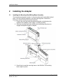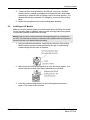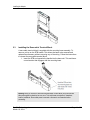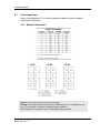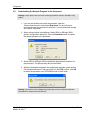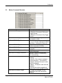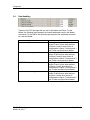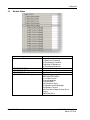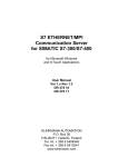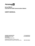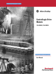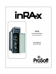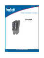
1
ILX34-MBS Quick Start Guide March 10, 2014 QUICK START GUIDE ILX34-MBS Quick Start Your Feedback Please We always want you to feel that you made the right decision to use our products. If you have suggestions, comments, compliments or complaints about our products, documentation, or support, please write or call us. How to Contact Us ProSoft Technology 5201 Truxtun Ave., 3rd Floor Bakersfield, CA 93309 +1 (661) 716-5100 +1 (661) 716-5101 (Fax) www.prosoft-technology.com [email protected] Copyright © 2014 ProSoft Technology, Inc., All Rights Reserved. ILX34-MBS Quick Start Guide March 10, 2014 ProSoft Technology® Product Documentation In an effort to conserve paper, ProSoft Technology no longer includes printed manuals with our product shipments. User Manuals, Datasheets, Sample Ladder Files, and Configuration Files are provided on the ® enclosed DVD in Adobe Acrobat Reader file format (.PDFs). These product documentation files may also be freely downloaded from our web site: www.prosoft-technology.com ProSoft Technology, Inc. March 10, 2014 Page 3 of 34 ILX34-MBS Quick Start Page 4 of 34 ProSoft Technology, Inc. March 5, 2014 ILX34-MBS Quick Start Contents Your Feedback Please ........................................................................................................................ 3 How to Contact Us .............................................................................................................................. 3 ® ProSoft Technology Product Documentation .................................................................................... 3 1 Start Here 1.1 1.2 1.3 2 ILX34-MBS Overview ................................................................................................ 7 Package Content ....................................................................................................... 7 System Requirements ............................................................................................... 7 Installing the Adapter 2.1 2.2 2.3 2.4 2.5 2.5.1 3 3.1.1 3.1.2 3.2 3.3 3.4 3.5 4 9 Installing the Mounting Base/Wiring Base Assembly ................................................ 9 Installing an I/O Module........................................................................................... 10 Installing the Removable Terminal Block ................................................................ 11 Removing a Mounting Base .................................................................................... 12 Connecting Power ................................................................................................... 13 Module Terminations ............................................................................................... 13 Configuration 3.1 15 Studio 5000 Logix Designer Project ........................................................................ 15 Create Module I/O Configuration ............................................................................ 18 Configure Controller Tags ....................................................................................... 24 Downloading the Sample Program to the Processor .............................................. 27 Master Command Structure .................................................................................... 28 Data Handling .......................................................................................................... 29 Module Status ......................................................................................................... 30 General Features & Specifications 31 General Specifications – Modbus Master/Slave .................................................... 31 Hardware Specifications.......................................................................................... 32 Agency Approvals ................................................................................................... 32 4.1 4.2 4.3 5 7 Support, Service & Warranty 33 Contacting Technical Support ........................................................................................................... 33 5.1 Warranty Information ............................................................................................... 34 ProSoft Technology, Inc. March 10, 2014 Page 5 of 34 Page 6 of 34 ProSoft Technology, Inc. March 10, 2014 Start Here 1 Start Here This Quick Start Guide will help you quickly set up and configure the ILX34-MBS module. You should be somewhat familiar with the following: Rockwell Automation® Studio 5000 Logix Designer v21 (for CompactLogix L1 processors) or Rockwell Automation® RSLogix™ 5000 version 16 or greater (for 1734 Point I/O adapters). Hardware Installation and Wiring 1.1 ILX34-MBS Overview The ILX34-MBS module is an ideal solution for many distributed I/O applications where Modbus connectivity can be integrated into an Allen Bradley system. The ILX34-MBSxxx comes with an Add-On profile and is configured using Rockwell Automation Studio 5000 (CompactLogix L1) and RSLogix 5000 (Point I/O™ Controllers). The module works in both the 1734 Point I/O adapters and the CompactLogix L1 processors. 1.2 Package Content The following components are included with your ILX34-MBS, and are all required for installation and configuration. Important: Before beginning the installation, please verify that all of the following items are present. 1.3 Qty. Part Name Part Number Part Description 1 ILX34-MBS ILX34-MBS POINT I/O Adapter System Requirements The ILX34-MBS requires the following minimum hardware and software components: Rockwell Automation® processor, with compatible power supply o CompactLogix™ L1 Processors or 1734- Point I/O adapters, Rockwell Automation RSLogix 5000/Studio 5000 programming software Rockwell Automation RSLinx communication software version 2.54 or higher Pentium® II 450 MHz minimum. Pentium III 733 MHz (or better) recommended Supported operating systems: ® o Microsoft Windows 7 o Microsoft Windows Vista o Microsoft Windows XP Professional with Service Pack 1 or 2 o Microsoft Windows 2000 Professional with Service Pack 1, 2, or 3 o Microsoft Windows Server 2003 ProSoft Technology, Inc. March 10, 2014 Page 7 of 34 Start Here 128 Mbytes of RAM minimum, 256 Mbytes of RAM recommended Microsoft Windows Explorer version 7 256-color VGA graphics adapter, 800 x 600 minimum resolution (True Color 1024 768 recommended) DVD drive Note: The Hardware and Operating System requirements in this list are the minimum recommended to install and run software provided by ProSoft Technology. Other third party applications may have different minimum requirements. Refer to the documentation for any third party applications for system requirements. Page 8 of 34 ProSoft Technology, Inc. March 10, 2014 Installing the Adapter 2 Installing the Adapter 2.1 Installing the Mounting Base/Wiring Base Assembly The wiring base assembly consists of a mounting base and a removable terminal block. You can install the assembly or just the mounting base. Perform the following to install the base/wiring base assembly: 1. Position the mounting base/wiring base assembly vertically above the installed units (adapter, power supply, or existing module). 2. Slide the mounting base down allowing the interlocking side pieces to engage the adjacent module or adapter. 3. Press firmly to seat the mounting base on the DIN Rail. The mounting base snaps into place. ProSoft Technology, Inc. March 10, 2014 Page 9 of 34 Installing the Adapter 4. To remove the mounting base from the DIN rail, remove any installed module (and any module immediately to the right) and use a small blade screwdriver to rotate the DIN rail locking screw to a vertical position. This releases the locking mechanism. Lift straight up to remove the mounting base. 5. Repeat this procedure for the next mounting base assembly. 2.2 Installing an I/O Module Make sure that the mounting base is correctly keyed before installing the module into the mounting base. In addition, make sure the mounting base locking screw is positioned horizontal referenced to the base. Warning: When you insert or remove the module while backplane power is on, an electrical arc can occur. This could cause an explosion in hazardous location installations. Be sure that power is removed or the area is non-hazardous before proceeding. 1. Using a small blade screwdriver, rotate the key switch on the mounting base clockwise until the number required for the type of module being installed aligns with the notch in the base. 2. Make certain the DIN-rail locking screw is in the horizontal position. You cannot insert the module if the locking mechanism is unlocked. 3. Insert the module straight down into the mounting base and press to secure. The module locks into place. Page 10 of 34 ProSoft Technology, Inc. March 10, 2014 Installing the Adapter 2.3 Installing the Removable Terminal Block A removable terminal block is supplied with the mounting base assembly. To remove, pull up on the RTB handle. This allows the base to be removed and replaced as necessary without removing any of the wiring. Follow the instructions to reinsert the removable terminal block: 1. Insert the RTB end opposite the handle into the base unit. This end has a curved section that engages with the mounting base. Warning: When you connect or disconnect the Removable Terminal Block (RTB) with the field side power applied, an electrical arc can occur. This could cause an explosion in hazardous location installations. Be sure that power is removed or the area is non-hazardous before proceeding. ProSoft Technology, Inc. March 10, 2014 Page 11 of 34 Installing the Adapter 2. Rotate the terminal block into the mounting base until it locks itself in place. 3. If an I/O module is installed, snap the RTB handle into place on the module. 2.4 Removing a Mounting Base In order to remove a mounting base, you must remove any installed module, and remove the Removable Terminal Block (if wired). 1. Unlatch the RTB handle on the I/O module. 2. Pull on the RTB handle to remove the Removable Terminal Block. Warning: When you connect or disconnect the Removable Terminal Block (RTB) with the field side power applied, an electrical arc can occur. This could cause an explosion in hazardous location installations. Be sure that power is removed or the area is non-hazardous before proceeding. 3. Press in on the module lock on the top of the module and pull up on the I/O module to remove from the base. Warning: When you insert or remove the module while backplane power is on, an electrical arc can occur. This could cause an explosion in a hazardous location. Be sure that power is removed or the area is non-hazardous before proceeding. 4. Remove the module to the right of the base you are removing (The interlocking portion of the base sits under the adjacent module.). 5. Use a small blade screwdriver to rotate the orange DIN-rail locking screw on the mounting base to a vertical position. This releases the locking mechanism. 6. Lift the mounting base straight up and remove. Page 12 of 34 ProSoft Technology, Inc. March 10, 2014 Installing the Adapter 2.5 Connecting Power Refer to the appropriate L1Y or Remote Adapter installation guides for adapter configuration instructions. 2.5.1 Module Terminations Caution: Do not connect 120/240V AC power to this supply. Warning: If you connect or disconnect wiring while the field-side power is on, an electrical arc can occur. This could cause an explosion in hazardous location installations. Be sure that power is removed or the area is nonhazardous before proceeding. ProSoft Technology, Inc. March 10, 2014 Page 13 of 34 Page 14 of 34 ProSoft Technology, Inc. March 10, 2014 Configuration 3 Configuration 3.1 Studio 5000 Logix Designer Project Note: If you are installing this module into a 1734-AENT, ADN, or ACNR, use RSLogix 5000 v16 or greater. The following example procedures are accomplished using Rockwell Automation's Studio 5000 Designer, but apply to RSLogix as well. 1. Open Studio 5000 and click Create New Project. 2. Expand CompactLogix 5370 Controller. Select the appropriate processor from the list: 1769-L16ER-BB1B 1769-L18ER-BB1B 1769-L18ERM-BB1B Note: If you are using a Point I/O adapter, you must configure the module using RSLogix 5000 version 16 or greater. That procedure is described later in this section. 3. Select the appropriate PLC and type in a Name for the Project. ProSoft Technology, Inc. March 10, 2014 Page 15 of 34 Configuration 4. Click Next. The Project Configuration dialog opens. 5. Select the Expansion I/O module number. If the modules present do not match the modules specified in the Project, unexpected control may occur. The Expansion I/O setting must match the actual number of modules. Page 16 of 34 ProSoft Technology, Inc. March 10, 2014 Configuration 6. Click Finish. The following window opens: ProSoft Technology, Inc. March 10, 2014 Page 17 of 34 Configuration 3.1.1 Create Module I/O Configuration 1. In the I/O Configuration folder, right-click on Expansion I/O and select New Module. The Select Module Type dialog opens. 2. Locate 1734-MODULE (Generic 1734 Module) by scrolling the list or using the Search filter. Page 18 of 34 ProSoft Technology, Inc. March 10, 2014 Configuration 3. Click Create. The New Module dialog opens. 4. Enter a Name for the module. 5. Enter Connection Parameters. The Connection Parameters section is dependent on the application that you are using. There are three different sizes allowed by the module. Register/Discrete Max Size per Modbus Message 8/128 24/384 36/576 Input Assy Instance 101 105 107 Input Size 34 66 90 Output Assy Instance 102 106 108 Output Size 26 58 82 Configuration Assy Instance 103 103 103 Configuration Size 38 38 38 6. Ensure that the Comm Format is set to Data-SINT and that the Slot field matches the slot number that the module will reside in. ProSoft Technology, Inc. March 10, 2014 Page 19 of 34 Configuration 7. Click OK. The Module Properties Report dialog opens. 8. Set the RPI time to a value larger than 30ms. 9. Click Apply. 10. Click OK. The module now appears under Expansion Module in the tree. Page 20 of 34 ProSoft Technology, Inc. March 10, 2014 Configuration 11. Under Tasks, expand Main Task > Main Program. 12. Double-click on the Main Routine to open it. ProSoft Technology, Inc. March 10, 2014 Page 21 of 34 Configuration 13. Right-click anywhere in the ladder and select Import Rungs... 14. Navigate to the location of the Add-On rung and click Import. The Import Configuration page opens. You can obtain the Add-On rung from http://psft.com/ilx34-mbs/dll. Page 22 of 34 ProSoft Technology, Inc. March 10, 2014 Configuration 15. Click OK. The Add-On rung appears in the Main Routine. 16. Double-click Controller Tags from the Controller Organizer. ProSoft Technology, Inc. March 10, 2014 Page 23 of 34 Configuration 17. The Controller Tags are now available for editing. 3.1.2 Configure Controller Tags 1. In the Data Types > User Defined folder, expand MBS_Config UDT. Page 24 of 34 ProSoft Technology, Inc. March 10, 2014 Configuration Serial Port Set the following parameters to configure the Serial Port. Controller Tag MBS_Config.Baud Rate MBS_Config.Serial Comm MBS_Config.Protocol Description 0=19200 2=2400 3=4800 4=9600 5=38400 0=7N2 1=7E1 2=8N1 5=8E1 6=8O1 0=ASCII 1=RTU Master Configuration The following parameters must be set to use the module as a Master. Controller Tag MBS_Config.Type MBS_Config.Timeout ProSoft Technology, Inc. March 10, 2014 Description Set this to “0” for Master Timeout in centiseconds. The time that the master waits for a response from the Slave. Page 25 of 34 Configuration The following example shows the module configured as a Master, 19200 baud, 8N1 (8 Data bits, No Parity, and 1 Stop Bit) Framing, RTU mode with a three second timeout. Slave Configuration Controller Tag MBS_Config.Type MBS_Config.Slave ID Description Set this to “1” for Slave. 1-255. Set this to the desired Slave ID that the Master is attempting to access. The Count parameters determine that maximum address that the Master can access for the ILX34-MBS. The default values represent the max addresses allowed for the provided Add-On instruction. Valid ranges are: 00001 – 00576, 10001 – 10576, 30001 – 30501 and 40001 – 40501... MBS.Config.Coldboot - If parameters change after initial configuration, use the Coldboot bit to initiate the changes. Page 26 of 34 ProSoft Technology, Inc. March 10, 2014 Configuration 3.2 Downloading the Sample Program to the Processor Warning: The key switch on the front of the ControlLogix processor must be in the REM or Prog position. 1. If you are not already online with the processor, open the Communications menu, and choose Download. You do not have to download through the processor’s serial port. You may download through any network connection. 2. When communication is established, Studio 5000 (or RSLogix 5000) opens a configuration dialog box. Click the Download button to transfer the sample program to the processor. 3. Studio 5000 (or RSLogix 5000) compiles the program and transfers it to the processor. This process may take a few minutes. 4. When the download completes, the configuration program opens another Confirmation dialog box. If the key switch is in the REM position, click OK to switch the processor from PROGRAM mode to RUN mode. Warning: If you receive an error message during these steps, refer to the Rockwell Automation documentation to interpret and correct the error. ProSoft Technology, Inc. March 10, 2014 Page 27 of 34 Configuration 3.3 Master Command Structure Controller Tag MBS.MASTERCMD[x].Enable MBS.MASTERCMD[x].Node MBS.MASTERCMD[x].Function MBS.MASTERCMD[x].DeviceAddress MBS.MASTERCMD[x].Count MBS.MASTERCMD[x].InternalAddress MBS.MASTERCMD[x].PollInterval MBS.MASTERCMD[x].Swap MBS.MASTERCMD[x].Trigger Page 28 of 34 Description 0=Disable 1=Enable the Command: Polling and Trigger allowed. 2=Enable the Command: Only Trigger allowed. Node address of the target device on the network (1-255). Function code for the command. 1, 2, 3, 4, 5, 6, 15 and 16 allowed for Master and Slave. 8 allowed for Slave only. Address in remote device associated with the command (0-65535). Number of points associated with the command. PLC Tag Internal address associated with the command. Minimum number of milliseconds between issuance of command (0-2, 147, 483, 647ms). 0=None. No change is made in byte ordering. 1=Words – The words are swapped. 2=Words & Bytes – The words are swapped, and then the bytes in each word are swapped. 3=Bytes – The bytes in each word are swapped. The words should be swapped only when using an even number of words. 1=Trigger the message. Can be triggered anytime the command is enabled. ProSoft Technology, Inc. March 10, 2014 Configuration 3.4 Data Handling These are the PLC data tags that are use for the Master and Slave. For the Master, the following tags represent the internal addresses used by the Master commands. For the Slave, the following tags represent the addresses accessed by a remote Master. Controller Tag MBS.DATA.InputBit MBS.DATA.InputRegister MBS.DATA.OutputBit MBS.DATA.OutputRegister ProSoft Technology, Inc. March 10, 2014 Description Incoming discreet data for address ranges 0x and 1x from other devices. Functions 5 and 15 when device is configured as a Slave. Functions and 1 and 2 when configured as a Master. Incoming register data for address ranges 3x and 4x from other devices. Functions 6 and 16 when device is configured as a Slave. Functions and 3 and 4 when configured as a Master. Outgoing discreet data for address ranges 0x and 1x from other devices. Functions 1 and 2 when device is configured as a Slave. Functions and 5 and 15 when configured as a Master. Outgoing register data for address ranges 3x and 4x from other devices. Functions 3 and 4 when device is configured as a Slave. Functions and 6 and 16 when configured as a Master. Page 29 of 34 Configuration 3.5 Module Status Controller Tag MBS.STATUS.Module MBS.STATUS.RXCnt MBS.STATUS.TXCnt MBS.STATUS.ErrorCnt MBS.STATUS.CmdError [x] Page 30 of 34 Description Module Status 1=Ready for Command 2=Processing Command 3=Waiting for Response 4=Processing Response Number of messages received Number of messages transmitted Number of errors The error represented for MBS.MASTERCMD[x]. 1= Invalid Function 2=Invalid Address 3=Invalid Data 20=Checksum Error 21=Modbus Invalid Message 22=Modbus Timeout 26=Float Word Swap Uneven Word Count 209=Parity Error ProSoft Technology, Inc. March 10, 2014 General Features & Specifications 4 General Features & Specifications 4.1 Add-On instruction creates UDTs, providing logical definitions for I/O, status, and control data Diagnostic data available in RSLogix 5000/Studio 5000 controller tags, allowing decisions to be made based upon node health Module configuration is backed up in the CompactLogix project (ACD file) Serial port enable/disabled through ladder logic Supports up to 1000 words of data Supports up to 30 Modbus commands and up to 36 words per command The Serial Port can be configured as a Modbus Master or Modbus Slave device Suitable for SCADA and field device interface applications General Specifications – Modbus Master/Slave Specification Configuration Environment Communication parameters Description RSLogix 5000/Studio 5000 Baud Rate: 110 to 38.4K baud Stop Bits: 1 or 2 Data Size: 7 or 8 bits Parity: None, Even, Odd Modbus Modes RTU mode (binary) with CRC-16 ASCII mode with LRC error checking Node Address 1 to 247 Modbus Function Codes Supported 1: Read Coil Status 2: Read Input Status 3: Read Holding Registers 4: Read Input Registers 5: Force (Write) Single Coil 6: Preset (Write) Single Holding Register 8: Diagnostics (Slave Only, Responds to Sub function 00) 15: Force(Write) Multiple Coils 16: Preset (Write) Multiple Holding Registers ProSoft Technology, Inc. March 10, 2014 Page 31 of 34 General Features & Specifications 4.2 Hardware Specifications Specification Pointbus current Number of Inputs Module Location LED Indicators Operating Temperature Storage Temperature Relative Humidity Dimensions (H x W x D) Shock Vibration ESD immunity 4.3 Description 75mA @ 5V DC 1 Full duplex 1734-TB or -TBS wiring base assembly (not included) 1 green/red module status indicator 1 green/red network status indicator 2 greed TXD, RXD status indicators -4°F to +131°F (-20°C to +55°C) -40°F to +185°F (-40°C to +85°C) 5% to 95% RH with no condensation 2.21 x 0.47 x 2.97 in 56 x 12 x 75.5 mm 30g Peak Acceleration (Operational) 50g Peak acceleration (Non-operational) Tested 5g @ 10-500Hz 6kV contact discharges 8kV air discharges Agency Approvals Agency Applicable Standard(s) UL/cUL Class 1, Div. 2 Groups A, B, C, D ATEX Category 3, Zone 2 CE Mark CB Safety Page 32 of 34 ProSoft Technology, Inc. March 10, 2014 Support, Service & Warranty 5 Support, Service & Warranty Contacting Technical Support ProSoft Technology, Inc. (ProSoft) is committed to providing the most efficient and effective support possible. Before calling, please gather the following information to assist in expediting this process: Product Version Number System architecture Network details If the issue is hardware related, we will also need information regarding: Module configuration and associated ladder files, if any Module operation and any unusual behavior Configuration/Debug status information LED patterns Details about the serial, Ethernet or fieldbus devices interfaced to the module, if any. Note: For technical support calls within the United States, an after-hours answering system allows 24-hour/7-days-a-week pager access to one of our qualified Technical and/or Application Support Engineers. Detailed contact information for all our worldwide locations is available on the following page. ProSoft Technology, Inc. March 10, 2014 Page 33 of 34 Support, Service & Warranty Internet Web Site: www.prosoft-technology.com/support E-mail address: [email protected] Asia Pacific (location in Malaysia) Tel: +603.7724.2080, E-mail: [email protected] Languages spoken include: Chinese, English Asia Pacific (location in China) Tel: +86.21.5187.7337 x888, E-mail: [email protected] Languages spoken include: Chinese, English Europe (location in Toulouse, France) Tel: +33 (0) 5.34.36.87.20, E-mail: [email protected] Languages spoken include: French, English Europe (location in Dubai, UAE) Tel: +971-4-214-6911, E-mail: [email protected] Languages spoken include: English, Hindi North America (location in California) Tel: +1.661.716.5100, E-mail: [email protected] Languages spoken include: English, Spanish Latin America (Oficina Regional) Tel: +1-281-2989109, E-Mail: [email protected] Languages spoken include: Spanish, English Latin America Tel: +52-222-3-99-6565, (location in Puebla, Mexico) E-mail: [email protected] Languages spoken include: Spanish Brasil (location in Sao Paulo) 5.1 Tel: +55-11-5083-3776, E-mail: [email protected] Languages spoken include: Portuguese, English Warranty Information For complete details regarding ProSoft Technology’s TERMS & CONDITIONS OF SALE, WARRANTY, SUPPORT, SERVICE AND RETURN MATERIAL AUTHORIZATION INSTRUCTIONS please see the documents on the Product DVD or go to www.prosoft-technology/warranty Documentation is subject to change without notice. Page 34 of 34 ProSoft Technology, Inc. March 10, 2014