1
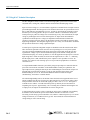
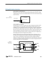
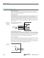
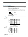
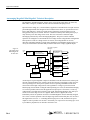
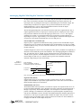
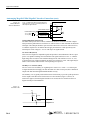
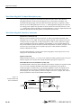
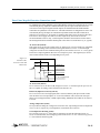
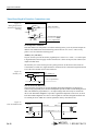
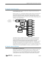
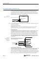
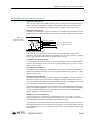
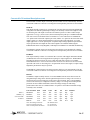
20
The MegaPAC™ Family
AC-DC, DC-DC Switching Power Supplies
Overview
The MegaPAC family is a line of field configurable switching power supplies that leverage
Vicor’s DC-DC converters to provide maximum flexibility. Developing a custom power supply
is as easy as selecting a MegaPAC chassis and sliding in the appropriate output assemblies,
called ConverterPACs. With five different chassis, five different ConverterPAC styles and
thousands of voltage and power combinations, there is a MegaPAC to fit almost any need.
Designing a customized power supply begins with selecting a chassis from the MegaPAC
family; the PFC MegaPAC, Autoranging MegaPAC, Mini MegaPAC, Three Phase MegaPAC or
DC MegaPAC. One or more can accept input voltages from 85 to 264Vac, 208/240 three phase,
or 10 to 380Vdc. Maximum output power ranges up to 4000W, and all five are fan cooled.
Standard features include output sequencing, general shutdown, AC OK and overcurrent
protection.
Customized design continues by selecting the ConverterPACs that meet your requirements. Each
ConverterPAC can be configured to provide one or two separate output voltages and up to 400W
of power. Multiple ConverterPACs can be connected in parallel to achieve higher power levels.
Best of all, ConverterPACs can be added or replaced with the turn of just one screw.
MegaPAC Family Products
Power Factor Corrected (PFC) MegaPAC
Technical Description . . . . . . . . . . . . . . . . . . . . . . . . . . . . . . . . . . . . . . . . . . . . . 20-2
Interface Connections . . . . . . . . . . . . . . . . . . . . . . . . . . . . . . . . . . . . . . . . . . . . . 20-3
Output Power Derating . . . . . . . . . . . . . . . . . . . . . . . . . . . . . . . . . . . . . . . . . . . . 20-5
Autoranging/Mini MegaPAC
Technical Description . . . . . . . . . . . . . . . . . . . . . . . . . . . . . . . . . . . . . . . . . . . . . 20-6
Interface Connections . . . . . . . . . . . . . . . . . . . . . . . . . . . . . . . . . . . . . . . . . . . . . 20-7
Three Phase MegaPAC
Technical Description . . . . . . . . . . . . . . . . . . . . . . . . . . . . . . . . . . . . . . . . . . . . . 20-9
Interface Connections . . . . . . . . . . . . . . . . . . . . . . . . . . . . . . . . . . . . . . . . . . . . . 20-10
DC MegaPAC
Technical Description . . . . . . . . . . . . . . . . . . . . . . . . . . . . . . . . . . . . . . . . . . . . . 20-13
Interface Connections . . . . . . . . . . . . . . . . . . . . . . . . . . . . . . . . . . . . . . . . . . . . . 20-13
Input Voltage Range and Vin OK Limits . . . . . . . . . . . . . . . . . . . . . . . . . . . . . . 20-16
ConverterPAC Functional Descriptions. . . . . . . . . . . . . . . . . . . . . . . . . . . . . . . 20-16
MegaPAC Mechanical Considerations. . . . . . . . . . . . . . . . . . . . . . . . . . . . . . . . 20-19
MegaPAC Do’s and Don’ts . . . . . . . . . . . . . . . . . . . . . . . . . . . . . . . . . . . . . . . . . 20-20
ConverterPAC Derating Curves . . . . . . . . . . . . . . . . . . . . . . . . . . . . . . . . . . . . . 20-21
12 1-800-927-9474
20-1
Applications Manual
PFC MegaPAC Technical Description
The PFC MegaPAC chassis consists of an off-line single phase, power factor corrected front
end, EMC filter, cooling fan, customer interface and associated housekeeping circuits.
Input AC mains voltage (L1, L2/N and GND) is applied to a terminal block. The input current is
passed through an EMC filter designed to meet conducted noise limit “B” specifications of FCC
Part 15 and VDE 0871 and EN55022 level “B”. At start-up, inrush current is limited by a PTC
thermistor prior to being passed to the power rectifiers. The PTC is shunted out shortly after
initial power-up by a DC bus voltage sense circuit driving a relay. After rectification, the input
voltage is put through a boost converter that keeps the AC input current sinusoidal and
synchronized with the input AC voltage (in compliance with EN61000 at nominal line
voltages). The boost converter delivers an unregulated 370Vdc to the hold-up capacitors and a
high voltage backplane. The backplane supplies power to a variety of ConverterPAC assemblies
that provide the desired low voltage, regulated outputs.
At initial power-up, the PFC MegaPAC outputs are disabled to limit the inrush current and to
allow the DC bus potential to settle out to the correct operating level. A low-power flyback
converter operating with PWM current-mode control converts the high voltage DC bus into
regulated low voltage to power the internal housekeeping circuits and DC cooling fan. The
internal housekeeping Vcc comes up within 1 sec after the application of input power. Once the
high voltage bus is within its limits, the AC Power OK signal asserts to a TTL “1” indicating
that the input power is OK, and allows the power outputs to come up within 15-30 ms. An
auxiliary Vcc output of 5Vdc sourcing up to 0.3A is provided for peripheral use on interface
connector J10-9.
An output Enable/Disable function is provided by using an optocoupler to control the Gate In
pins of the ConverterPAC assemblies. If the Enable/Disable control pin is pulled low, the
optocoupler turns on, pulling the Gate In pin low and disabling the ConverterPAC output. The
nominal delay associated for an output to come up when measured from release of the
Enable/Disable pin is 5-10 ms. The General Shutdown function controls all outputs
simultaneously, and works in a similar manner.
The ride-through (holdup) time is the amount of time the load can be supported before loss of
output regulation after the loss of input power. Detecting the loss of input power takes a finite
time period after which the AC Power OK signal goes from a TTL “1” to “0”. This signal is
available for use within 1.2 seconds after initial power-up and may be used to indicate an
impending loss of power. Approximately 3 ms of warning time is obtained. Following the loss
of input power, the outputs are disabled after AC Power OK goes low.
A fault-clearing device such as a fuse is required per safety agency conditions of acceptability.
It should be sized to handle the specific load conditions but not to exceed 20A. 6 to 20A
fast-acting ceramic body type fuses should be used, 3AB-6 to 3AB-20 respectively. For current
ratings less than 6A, use a 3AB slow-blow type fuse. Fuses should be sized with sufficient
voltage rating as well as current rating.
20-2
12 1-800-927-9474
MegaPAC™ Family AC-DC, DC-DC Switchers
PFC MegaPAC Interface Connections
Chassis Input Power Terminals (J9)
Input AC power is applied to terminal block J9, using a pressure screw terminal that accepts a
maximum wire size of 12 AWG. The maximum torque recommended is 10 in-lbs. J9-1 (GND)
is Earth Ground for safety; J9-2 (L2) is the Hot connection; J9-3 (L1/N) is the other Hot or input
Neutral connection.
Figure 1.
Input Connector J9
PFC MegaPAC
Input: 85-264Vac
F1
J9 Input Power Connection
3
2
1
L1
L2
Earth Ground
Chassis Output Power Terminals
Depending on the ConverterPAC used, there are two types of output power terminals available
in the PFC MegaPAC. For single output assemblies (ModuPAC/RamPAC/BatPAC), these
terminals are two 1/4-20 plated steel bolts. The positive polarity of the output is the upper bolt.
For DualPACs there is a 6-pin Molex connector for each output (J1A, J1B). For both connectors
pins 1 and 4 are the +Output, and pins 2 and 5 are the –Output. Pins 3 and 6 are duplicates of
the remote sense pins present on J2A and J2B. The top connector, J1B, provides the first voltage
listed on the DualPAC, while the bottom connector, J1A, provides the second voltage. Each
power output is isolated; thus outputs of positive or negative polarity may be configured by the
user through proper selection of an output reference terminal.
In order to minimize parasitic cable inductance and reduce EMC, the output power cables
should be routed in close proximity to one another, and large current loops should be avoided.
To avoid excessive voltage drop, do not undersize power cables, especially for high current
outputs. Excessive cable inductance coupled with large capacitive loading can introduce
instability in switching power supplies. This problem can be avoided with proper system design.
Consult Vicor’s Applications Engineering Department for assistance with applications that use
long cable lengths and excessive load capacitance.
Figure 2.
Output Power
Connections
J9
+
3
L1
+Out
+
DC-DC
AC-DC
L2
Fuse
2
-
-
+Sense
-Sense
-Out
+Out
+
+Sense
Ground
DC-DC
1
-
12 1-800-927-9474
-Sense
-Out
+P
J2-2
Positive
Output
J2-3
-P
+P
Logic
Ground
J2-2
J2-3
-P
Negative
Output
20-3
Applications Manual
PFC Interface Connections (cont)
Signal Ground (J10-10)
Signal Ground on J10-10 is an isolated secondary ground reference for all J10 interfacing
signals, and for ModuPAC output status signals such as Power Good. This is not the same as
Earth Ground on input power connector J9.
Enable/Disable (J10-8)
The Enable/Disable control pins allow ConverterPAC outputs to be sequenced either on or off.
J10-1 through J10-8 are the control pins for output positions 1 through 8, respectively. For
DualPACs, both outputs are sequenced. In parallel arrays, only the driver ModuPAC need be
controlled. The Enable/Disable pins should be pulled low to less than 0.7V with respect to
Signal Ground to disable the outputs. They will source 10mA maximum. These pins should be
open circuited or allowed to exceed 4.5V when enabled. Do not apply more than 5V to these
inputs at any time.
Figure 3.
Enable/Disable
and General
Shutdown
A TTL "1" applied to the base of the transistor turns
output OFF. Pin 1 (or Pin 12 for GSD) is pulled Low
with respect to Signal Ground.
J10
9
Enable/Disable Output 1
PFC MegaPAC
Vcc
1
Enable/Disable Control
General Shutdown
1
0
TTL "1" (OFF)
TTL "0" (ON)
Signal Ground
12
10
General Shutdown GSD (J10-12)
The GSD control pin on J10-12 allows simultaneous shutdown of all ConverterPAC outputs.
This pin must be pulled down to less than 0.7V, and will source 13 mA maximum to shut down
all outputs. The GSD pin should be open circuited or allowed to exceed 4.5V when not in use,
or when the outputs are to be enabled. Do not apply more than 5V to this input at any time.
Normal open circuit voltage is 1.5 to 3V with respect to Signal Ground.
AC Power OK (J10-11)
This is an active high TTL compatible signal, and provides a status indication of the AC input
power. It is capable of sinking 20 mA maximum. This signal switches to a TTL “1” when the
high voltage bus exceeds low-line condition during turn-on, and switches to a TTL “0” 3 ms
(typical) before loss of output regulation due to the loss of input AC power. This signal may be
used to warn external control circuits of an impending loss of power.
Figure 4.
AC Power OK
J10
+5V
10K
2.49K
11 AC Power OK
PN2222
10 Signal Ground
20-4
12 1-800-927-9474
MegaPAC™ Family AC-DC, DC-DC Switchers
PFC Interface Connections (cont)
Auxiliary Vcc +5V/0.3A (J10-9)
The Vcc on J10-9 is an auxiliary 5V regulated power source. It is +5Vdc +/–5% with respect to
Signal Ground, and can supply 300 mA maximum. It is short circuit proof, but if shorted all
outputs will shut down through the Enable/Disable circuitry.
The Auxiliary Vcc is typically used with the Power Good circuitry to provide a pull-up
reference for the outputs of the DC Power Good circuit on a ModuPAC (Figure 5, below). If
used for this purpose, then the Signal Ground on J10-10 must also be connected to the J3-4
Signal Ground pin of the ModuPAC.
Figure 5.
Auxiliary Vcc
J10
9 Auxiliary Vcc
+5V/300 mA
78M05
0.1 µF
10 Signal Ground
PFC MegaPAC Output Power Derating
PFC MegaPAC Output Power vs. Input Voltage (Vac)
Figure 6.
Maximum
Output Power vs.
AC Input Voltage
1600W @ 145Vac
Output Power (Watts)
1600
Power
Exceeded
Derate at 10 Watts/Volt
1400
Safe Operating Area
1200
1000
85 100
105
125
150
175
200
145
Input Voltage (Vac)
225
250 264
PFC MegaPAC Output Power vs. Input Voltage (Vdc)
Figure 7.
Maximum
Output Power vs.
DC Input Voltage
1600W @ 150Vdc
Output Power (Watts)
1600
1500
Power
Exceeded
1400
1350
1300
Derate at 10Watts/Volt
Safe Operating Area
1200
1100
1000
100 125 150
(Min. Input)
200
250
300
350 380
(Max. Input)
Input Voltage (Vdc)
12 1-800-927-9474
20-5
Applications Manual
Autoranging MegaPAC/Mini MegaPAC Technical Description
The MegaPAC and Mini MegaPAC chassis consist of an off-line single phase AC front end,
EMC filter, cooling fan, customer interface and associated housekeeping circuits.
Input AC mains voltage (L1, L2/N and GND) is applied to a terminal block. The input current is
passed through an EMC filter designed to meet conducted noise limit “A” specifications of FCC
Part 15 and VDE 0871. At start-up, inrush current is limited by an NTC thermistor prior to
being passed to the power rectifiers. The NTC is shunted out shortly after initial power-up by a
relay driven by a DC bus voltage sense circuit. The sense circuit also controls the input
autoranging selection relay on the autoranging MegaPAC. The power rectifiers and filter
capacitors are arranged in a conventional full wave bridge rectifier/voltage doubler configuration.
This operates as a full wave bridge rectifier on 230Vac, and voltage doubler on 115Vac,
delivering unregulated 300Vdc to a high voltage backplane. The backplane supplies power to a
variety of ConverterPAC assemblies that provide the desired low voltage, regulated outputs.
Figure 8.
MegaPAC and
Mini MegaPAC
Architecture
High Voltage Unregulated
300Vdc Bus
Power
Input
FCC/VDE "A"
EMI Filter
AC-DC Power Rectification,
Input Autoranging,
Inrush Current Limiting
Power Output
DC-DC Output
Assembly #1
Power Output
Inrush Current &
Autoranging
Control
DC-DC Output
Assembly #2
Power Output
DC-DC Output
Assembly #3
DC
Fan
Logic Power
Supply
Power Output
Housekeeping
Circuits
DC Bus Sense
DC-DC Output
Assembly #4
Control
Power Output
Customer Interface
(Optoisolators)
DC-DC Output
Assembly #5
At initial power-up, the MegaPAC outputs are disabled to limit the inrush current, reduce peak
currents in the autoranging relay contacts, and to allow the DC bus potential to settle out to the
correct operating level. A low-power flyback converter operating with PWM current-mode
control converts the high voltage DC bus into regulated low voltage to power the internal
housekeeping circuits and DC cooling fan. When operating on 115Vac, the internal housekeeping
Vcc comes up within 1,000 ms after the application of input power. On 230Vac, it comes up
within 500 ms. The input range selection circuit in the Autoranging MegaPAC may take up to
200 ms to select the range if 115Vac is applied. When 230Vac is applied, the circuit
immediately selects for operation on 230Vac. The Mini MegaPAC must be manually strapped
for 115Vac or 230Vac operation. Once the input range selection has taken place, the AC Power
OK signal asserts to a TTL “1” indicating that the input power is OK, and allows the power
outputs to come up within 15-30 ms later. An auxiliary Vcc output of 5Vdc sourcing up to 0.3A
is provided for peripheral use on interface connector J10-9.
20-6
12 1-800-927-9474
MegaPAC™ Family AC-DC, DC-DC Switchers
Autoranging MegaPAC/Mini MegaPAC Interface Connections
An output Enable/Disable function is provided by using an optocoupler to control the Gate In
pins of the ConverterPAC assemblies. If the Enable/Disable control pin is pulled low, the
optocoupler turns on, pulling the Gate In pin low and disabling the ConverterPAC output. The
nominal delay associated for an output to come up when measured from release of the
Enable/Disable pin is 5-10 ms. The General Shutdown function controls all outputs
simultaneously, and works in a similar manner.
The ride-through (holdup) time is the amount of time the load can be supported before loss of
output regulation after the loss of input power. Detecting the loss of input power takes a finite
time period after which the AC Power OK signal goes from a TTL “1” to “0”. This signal is
available for use within 1.2 seconds after initial power-up and may be used to indicate an
impending loss of power. Approximately 3 ms of warning time is obtained. Following the loss
of input power, the outputs are disabled after AC Power OK goes low.
Chassis Input Power Terminals (J9)
Input AC power is applied to terminal block J9, using a pressure screw terminal that accepts a
maximum wire size of 10 AWG. The maximum torque recommended is 10 in-lbs. J9-1 (GND)
is Earth Ground for safety; J9-2 (L2) is the Hot connection; J9-3 (L1/N) is the other Hot or input
Neutral connection.
A fault clearing device such as a fuse is required per safety agency conditions of acceptability. It
should be sized to handle the specific load conditions. The Autoranging MegaPAC should use a
max. 30A fast-blow fuse for 1200W, 115Vac operation and a max. 25A fast-blow fuse for
1600W, 230Vac operation. The Mini MegaPAC should use a 25A max. fast blow fuse. For
current ratings less than 6A, use a 3AB slow-blow type fuse. Fuses should be sized with
sufficient voltage rating as well as current rating.
Figure 9.
Input Power
Connections
Input: Autoranging
90-132, or 180-264Vac, 47-500 Hz
or 260-380Vdc (optional, consult factory)
MegaPAC/Mini MegaPAC
Input Power
Terminal Block
J9
F1
L1/N (or DC–)
L2 (or DC+)
3
2
L1/N
L2
1
Earth Ground
Note: An input fault clearing device, such as fuse F1 or a circuit breaker is recommended.
Signal Ground (J10-10)
Signal Ground on J10-10 is an isolated secondary ground reference for all J10 interfacing
signals, and for ModuPAC output status signals such as Power Good. This is not the same as
Earth Ground on input power connector J9.
Enable/Disable (J10-1 to 8)
The Enable/Disable control pins allow ConverterPAC outputs to be sequenced either on or off.
For the Autoranging MegaPAC, J10-1 through J10-8 are the control pins for output positions 1
through 8, respectively. For the Mini MegaPAC, J10-1 through J10-5 control the outputs for
position 1 through 5. For DualPACs, both outputs are sequenced together. In parallel arrays,
only the driver ModuPAC need be controlled. The Enable/Disable pins should be pulled low to
less than 0.7V with respect to Signal Ground to disable the outputs. They will source 10 mA
maximum. These pins should be open circuited or allowed to exceed 4.5V when enabled. Do
not apply more than 8V to these inputs at any time.
12 1-800-927-9474
20-7
Applications Manual
Autoranging MegaPAC/Mini MegaPAC Interface Connections (cont)
Figure 10.
Enable/Disable
General Shutdown
A TTL "1" applied to the base of the transistor turns
output OFF. Pin 1 (or Pin 12 for GSD) is pulled Low
with respect to Signal Ground.
J10
9
Enable/Disable Output 1
PFC MegaPAC
Vcc
1
Enable/Disable Control
1
0
TTL "1" (OFF)
TTL "0" (ON)
General Shutdown
Signal Ground
12
10
General Shutdown GSD (J10-12)
The GSD control pin on J10-12 allows simultaneous shutdown of all ConverterPAC outputs.
This pin must be pulled down to less than 0.7V, and will source 13 mA maximum to shut down
all outputs. The GSD pin should be open circuited or allowed to exceed 4.5V when not in use,
or when the outputs are to be enabled. Do not apply more than 8V to this input at any time.
Normal open circuit voltage is 1.5 to 3V with respect to Signal Ground.
AC Power OK (J10-11)
This is an active high TTL compatible signal, and provides a status indication of the AC input
power. It is capable of sinking 20 mA maximum. This signal switches to a TTL “1” when the
high voltage bus exceeds low-line condition during turn-on, and switches to a TTL “0” 3 ms
(typical) before loss of output regulation due to the loss of input AC power. This signal may be
used to warn external control circuits of an impending loss of power.
Auxiliary Vcc +5V/0.3A (J10-9)
The Vcc on J10-9 is an auxiliary 5V regulated power source. It is +5Vdc +/–5% with respect
to Signal Ground, and can supply 300 mA maximum. It is short circuit proof, but if shorted all
outputs will shut down through the Enable/Disable circuitry.
The Auxiliary Vcc is typically used with the Power Good circuitry to provide a pull-up reference
for the outputs of the DC Power Good circuit on a ConverterPAC (Figure 11, below). If
used for this purpose, then the Signal Ground on J10-10 must also be connected to the J3-4
Signal Ground pin of the ModuPAC.
Figure 11.
AC Power OK
J10
+5V
10K
2.49K
11 AC Power OK
PN2222
10 Signal Ground
20-8
12 1-800-927-9474
MegaPAC™ Family AC-DC, DC-DC Switchers
Autoranging MegaPAC/Mini MegaPAC Interface Connections (cont)
Vcc (J3-1)
The Vcc on J3-1 is an input that requires +5V either from the Auxiliary Vcc on J10-9, or from
another source. Input current to this pin is limited by an internal resistor to 3 mA. If the
Auxiliary Vcc on J10-9 is connected to Vcc on J3-1, then Signal Ground J10-10 must also be
connected to Signal Ground on J3-4.
Three Phase MegaPAC Technical Description
A Three Phase MegaPAC is configured by installing DC-DC ConverterPAC assemblies into a
three phase front-end chassis. The chassis takes three phase AC input power and performs
filtering and rectification functions. The ConverterPACs plug into a high-voltage backplane and
provide low-noise, independently regulated and fully isolated outputs.
Three Phase MegaPAC Chassis
Input AC mains voltage (L1, L2, L3 and GND) is applied to an agency-approved mating plug.
The input current is passed through an EMC filter designed to meet conducted noise limit "A"
specifications of FCC Part 15 and VDE 0871, before it is passed to a three-phase full-wave
bridge rectifier. The rectifier charges-up storage capacitors and delivers unregulated 300Vdc to
a backplane after passing through a large choke that improves input power factor. The power
factor typically exceeds 0.9 depending upon load, line voltage, frequency and line balance.
Inrush current is actively controlled with an IGBT and never exceeds 30A peak regardless of
hot or cold starts. The backplane supplies power to a variety of ConverterPAC assemblies that
provide the desired low-voltage, regulated outputs.
A housekeeping supply, isolated from the AC input, powers the brushless DC cooling fan and
other input monitoring circuits, in addition to providing an auxiliary +5V power source for the
user. Excessive input currents caused by loss of a phase, or excessive output loading in single
phase operation, will safely shut down the unit and provide a phase fail indication until input
power is recycled. This occurs when the peak input current reaches 30A. Analog and digital
temperature monitors are provided, as well as overtemperature shutdown. An active-high TTL
compatible, Enable control is included for each ConverterPAC assembly, as well as an
active-low General Shutdown control; the polarities, active-high or active-low, are factory set.
Three Phase MegaPACs can be safely paralleled with accurate current sharing for high power
systems. All interface signals are safety-isolated using a common floating return.
Figure 12.
Three-Phase MegaPAC
Architecture
J1
Input
Power
FCC/VDE
"A" EMI
Filter
3 Phase
Full-Wave
Rectifier
IGBT PFC Choke
Start-up Control
Circuits
Housekeeping
Power Supply
J10
Customer
Interface
Opto-isolated
Control/Status
DC Brushless
Cooling Fan
3-Phase MegaPAC Chassis
12 1-800-927-9474
Fuse
+P, -P
Output
Power
DC-DC
Converter
J2
Remote Sense,
Trim Interface
J3
Power Good
Interface
ConverterPAC (Up to 10)
20-9
Applications Manual
Three Phase MegaPAC Technical Description (cont)
Upon power-up, all outputs are first disabled to limit the inrush current, and to allow the
unregulated 300Vdc to reach correct operating levels for ConverterPAC assemblies. The
internal housekeeping supply comes up within 500 ms after input power is applied, at which
time the AC Power OK signal asserts to a TTL “1,” indicating that the input power is OK. The
low-voltage power outputs come up within 10-20 ms after the AC Power OK asserts to a TTL
“1.” Output ramp-up time from Enable or General Shutdown is 10-20 ms. Output fall time from
Disable is dependent on load, but typically a few hundred microseconds.
Three Phase MegaPAC Interface Connections
Input Power Connections (J1)
Input AC power is applied to a plug-in connector, J1, that accepts soldered terminals with a
maximum wire size of 12 AWG. For operation on high voltage DC input, input power may be
connected to any two input lines. A fault-clearing device, such as a fuse, at the power supply
input is required per safety agency conditions of acceptability. A user-accessible input fuse is
not present within the unit. For an output of 2000W with operation on 208Vac, 3Ø input, a 20A
slow-blow fuse in each input line is acceptable. Input power cables should be shielded to
minimize radiated noise effects.
The Three Phase MegaPAC can also operate from a single phase 230Vac input; however, the
output power must be limited to 1200W.
Signal Ground (J10)
Signal Ground on J10 pins 1, 2, 12, and 15 is an isolated secondary ground reference for all J10
interface signals. This is not the same as Earth Ground on input power connector J1.
Enable/Disable and General Shutdown (GSD) (J10)
The Enable/Disable control lines allow individual ConverterPAC outputs to be sequenced either
on or off via TTL compatible HCMOS control inputs. For DualPACs, both outputs are
sequenced together. In parallel arrays, only the driver ModuPAC needs to be sequenced. The
GSD control line on J10-5 allows simultaneous shutdown of all ConverterPAC outputs. An
internal jumper, JP2, selects polarity, either active-high or active-low. A jumper, JP1, selects a
pull-up or pull-down source for the HCMOS control inputs.
Figure 13.
Enable/Disable and
General Shutdown
J10
+5V
JP1
Enable/Disable
24
10K
10K
General Shutdown
2N2222
5
1 µF
Signal Ground 1, 2, 12, 15
20-10
74HC86
+5V
JP2
12 1-800-927-9474
MegaPAC™ Family AC-DC, DC-DC Switchers
Three Phase MegaPAC Interface Connections (cont)
For standard Three Phase MegaPACs, the Enable/Disable controls are configured as active-high
with internal pull-up; outputs are enabled when these pins are open-circuited or allowed to
exceed 4.5V with respect to Signal Ground. Outputs are disabled when the Enable/Disable
control lines are pulled low to less than 0.7V. The GSD control line is configured to be active-low
with internal pull-up; all outputs are simultaneously inhibited when the GSD control line is
pulled low to less than 0.7V. All outputs are enabled when GSD is open circuited or allowed to
exceed 4.5V. Do not apply more than 5V to these inputs at any time. If driven from an
electromechanical switch or relay, a small capacitor should be connected between the control
line and Signal Ground to eliminate latch-up due to the effects of switch bounce (1 µF, typical).
AC Power OK (J10-18)
This signal on J10-18 provides a status of the AC input power. It is active high, TTL compatible
and capable of sinking 10 mA maximum. This signal switches to a TTL “1” when the high
voltage bus exceeds low-line condition during turn-on, and switches to a TTL “0” 3 ms (typical)
before loss of output regulation due to the loss of input AC power. This signal may be used to
warn external control circuits of an impending loss of power.
Figure 14.
AC Power OK,
AC Power Fail and
Phase Fail
J10
+5V
4.99K
14 Phase Fail
2.49K
18 AC Power OK
2N2222
10K
2.49K
19 AC Power Fail
1, 2, 12, 15 Signal Ground
AC Power Fail (J10-19)
J10-19 is the inverse of AC Power OK, and goes to a TTL “1” when the input AC power is not
OK. It is capable of sinking 10 mA maximum. The fan out is 20.
Phase Fail (Input Overcurrent) (J10-14)
J10-14 is a TTL level active-high signal, that is asserted when the peak input current reaches
30A due to the loss of an input phase, or severe line imbalance. This occurs when one input
phase is lost with approximately 1400W output loading. Maximum current that can be sourced
is 10 mA.
Analog Temperature (J10-4)
J10-4 provides an analog DC voltage between 0V and 10V, representing an inlet air temperature
of 0˚C to 100˚C, respectively. The temperature is monitored close to the fan.
Overtemperature Warning (J10-3)
J10-3 asserts a TTL level “1” if the inlet air temperature exceeds the following factory set
levels. For standard units, the warning trip point is between 65˚C to 76˚C. The recovery point is
1˚C lower than the actual trip point.
12 1-800-927-9474
20-11
Applications Manual
Three Phase MegaPAC Interface Connections (cont)
Figure 15.
Analog Temperature
and Overtemperature
Warning
J10
MC34074
100
+
4.99K
4 Analog Temperature
4.99K
100K
4.99K
+
Vref
+5V
3 Overtemperature Warning
1, 2, 12, 15 Signal Ground
LM393
Overtemperature Shutdown
If the inlet ambient air temperature exceeds the following factory set levels, then all outputs are
disabled. For standard units the shutdown trip point is between 70˚C to 81˚C. The recovery
point is 10˚C lower than the actual trip point.
Auxiliary Vcc (J10-16,17)
J10 pins 16 and 17 provide an auxiliary regulated power source. It is +5Vdc +/–5% with respect
to Signal Ground, and can supply 300 mA maximum. It is short circuit proof, but if shorted, all
outputs will shut down.
The Auxiliary Vcc can be used to provide a pull-up reference for the Power Good circuit on
ConverterPACs. In this case, Signal Ground on J10 must also be connected to Signal Ground on
J3-4 of the ConverterPAC Power Good connector.
Figure 16.
Auxiliary Vcc
J10
16, 17 Auxiliary Vcc
+5V/300 mA
78M05
0.1 µF
1, 2, 12, 15 Signal Ground
Gate-In, Gate-Out (J10-13,25)
Gate-In and Gate-Out signals are used for paralleling Three Phase MegaPACs for high power
systems using a proprietary driver/booster technique that provides accurate current sharing between
units. One channel may be paralleled, i.e., one output voltage from unit #1 may be connected to
unit #2. The Three Phase MegaPAC #1 provides a signal from output slot #10 at J10-25, to slot #1
in the Three-Phase MegaPAC #2 at J10-13. These signals are referenced to Signal Ground on J10.
Use twisted pair 20-22 AWG wires. Do not separate the units by more than six feet.
Figure 17.
Gate-In and Gate-Out
3-Phase MegaPAC #1
Slot 10
J10
25 Gate Out
J10
Gate In 13
3-Phase MegaPAC #2
Slot 1
1, 2, 12, 15 Signal Ground 1, 2, 12, 15
0.01 µF
1 kV
Use 20-22 AWG Twisted Pair Wires
20-12
12 1-800-927-9474
MegaPAC™ Family AC-DC, DC-DC Switchers
DC MegaPAC Technical Description
The DC MegaPAC chassis consists of an EMC filter, cooling fan, customer interface and
associated housekeeping circuits.
Input DC voltage (+Vin, –Vin and GND) is applied to the input connectors. The input current is
passed through an EMC filter designed to meet British Telecom specifications. At start-up,
inrush current is limited by a thermistor. The thermistor is shunted out shortly after initial
power-up by a relay driven by a DC bus voltage sense circuit. The DC voltage is then fed to the
backplane. The backplane supplies power to a variety of ConverterPAC assemblies that provide
the desired voltage, regulated outputs.
Figure 18.
DC MegaPAC
Architecture
Power
Input
EMI Filter
Under, Over & Reverse
Voltage Protection
Inrush Current Limiting
Under, Over &
Reverse Voltage
Control
DC
Fan
Logic Power
Supply
Housekeeping
Circuits
Customer Interface
(Otpo-Isolators)
DC Bus Sense
Control
DC-DC Output
Assembly #1
Power
Output
DC-DC Output
Assembly #2
Power
Output
DC-DC Output
Assembly #3
Power
Output
DC-DC Output
Assembly #4
Power
Output
DC-DC Output
Assembly #5
Power
Output
DC-DC Output
Assembly #6
Power
Output
DC-DC Output
Assembly #7
Power
Output
DC-DC Output
Assembly #8
Power
Output
At initial power-up, the DC MegaPAC outputs are disabled to limit the inrush current and to
allow the DC bus potential to charge to the operating level. A low-power flyback converter
operating with PWM current-mode control converts the voltage DC bus into regulated low
voltage to power the internal housekeeping circuits and DC cooling fan. The internal
housekeeping Vcc comes up within three seconds after the application of input power. Once the
input range is within specification, the Vin OK signal asserts to a TTL “1” indicating that the
input voltage is OK, and allows the power outputs to be enabled. The power outputs will be in
regulation 500 ms after the Vin OK signal asserts to a TTL “1”. An auxiliary Vcc output of 5Vdc
sourcing up to 0.3A is provided for peripheral use on interface connector J10-16 and J10-17.
DC MegaPAC Interface Connections
Chassis Input Power Terminals (J9)
Input DC power is applied to solderless lugs J9, using a wire size of 2 AWG. J9-1 is the +DC
Voltage IN connection and J9-3 is the -DC Voltage IN connection. The Earth Ground is
accessed via J9-2, a size 10-32 self-locking PEM nut. Max. torque recommended is 25 in-lbs.
A fault clearing device such as a fuse or circuit breaker at the power supply input is strongly
recommended. For an output of 1600W with operation on 48Vdc (and low line operation
12 1-800-927-9474
20-13
Applications Manual
DC MegaPAC Interface Connections (cont)
of 42V), a fast-blow fuse of 50 Amps is recommended. Start-up inrush current is limited by a
10Ω thermistor and in most cases will be less than nominal line current during operation.
Start-up inrush current can be calculated by I = MaxVin/10 (where MaxVin is the maximum
operating voltage, see Table 1, page 20-16). Example: for a nominal 48V input, the maximum
operating voltage is 60V, therefore, I = 60V/10 = 6 Amps.
Figure 19.
Input Connector J9
DC MegaPAC
Input: 12, 24, 36, 48 or 72Vdc
J9 Input Power Connection
–
3
2
1
+
–Vin
Earth Ground
+ Vin
F1
NOTE: An input fault clearing device such as fuse F1, or a circuit breaker is required per safety agency
conditions of acceptability.
Signal Ground (J10-1,2,12,15)
Signal Ground on J10-1, 2, 12 and 15 are isolated secondary ground references for all J10
interfacing signals. This is not the same as Earth Ground on input power connector J9.
Enable/Disable (J10)
The Enable/Disable control pins allow ConverterPAC outputs to be sequenced either on or off;
see outline drawing for locations. For DualPACs, both outputs are sequenced together. In
parallel arrays, only the driver ConverterPAC need be controlled. The Enable/Disable pins
should be pulled low to less than 0.7V with respect to Signal Ground to disable the outputs.
They will source 8 mA maximum. These pins should be open circuited or allowed to exceed
4.5V when enabled. Do not apply more than 8V to these inputs at any time. If driven from an
electromechanical switch or relay, a capacitor should be connected to eliminate the effects of
switch bounce.
Figure 20.
Enable/Disable
and General
Shutdown
A TTL "1" applied to the base of the transistor turns
output OFF. Pin 24 (or Pin 5 for GSD) is pulled Low
with respect to Signal Ground.
DC MegaPAC
J10
16
Enable/Disable Output 1
Vcc
24
Enable/Disable Control
TTL "1" (OFF)
TTL "0" (ON)
1
0
General Shutdown
Signal Ground
5
1
General Shutdown (GSD) (J10-5)
The GSD control pin on J10-5 allows simultaneous shutdown of all ConverterPAC outputs. This
pin must be pulled low to less than 0.7V, and will source 8 mA maximum to shut down all
outputs. The GSD pin should be open circuited or allowed to exceed 4.5V when not in use, or
when the outputs are to be enabled. Do not apply more than 8V to this input at any time. Normal
open circuit voltage is 1.5 to 3V with respect to Signal Ground. If driven from an electromechanical
switch or relay, a capacitor should be connected to eliminate the effects of switch bounce.
20-14
12 1-800-927-9474
MegaPAC™ Family AC-DC, DC-DC Switchers
DC MegaPAC Interface Connections (cont)
Input Power OK (J10-18)
This is an active high TTL compatible signal on pin J10-18, and provides a status indication of
the DC input power. It is capable of sinking 20 mA maximum. This signal switches to a TTL
“1” when Vin voltage is within specification. See Table 1, page 20-16 for specifications.
Input Power Fail (J10-19)
The Input Power Fail signal on pin J10-19 is the inverse of the Input Power OK signal on J10-18,
and goes to a TTL “0” when the input DC power is OK. It is capable of sinking 20 mA maximum.
Figure 21.
Input Power OK,
Input Power Fail
DC MegaPAC
J10
2.49K
2.49K
16
18
10K
19
1
Auxiliary Vcc (+5V/0.3A)
Input Power OK
Input Power Fail
TTL "1": DC Input Power is OK
TTL "0": DC Input Power is OK
Signal Ground
Analog Temperature (J10-4)
This signal on J10-4, referenced to Signal Ground, provides an analog DC voltage output
between 0V and 10V that represents the air temperature of 0˚C to 100˚C, respectively, inside the
power supply. The inlet air temperature is monitored close to the fan.
Overtemperature Warning (J10-3)
J10-3 is a signal that asserts a TTL level “1” if the air temperature exceeds the following factory
set levels. The warning trip point is 65˚C to 76˚C typically and the recovery point is 1˚C lower
than the actual trip point.
Overtemperature Shutdown
If the inlet ambient air temperature exceeds the following factory set levels, then the outputs are
disabled. The shutdown trip point is 70˚C to 81˚C typically and the recovery point is 10˚C lower
than the actual trip point.
Gate In/Gate Out (J10-13,25)
The Gate In and Gate Out signals are used for paralleling DC MegaPACs for power expansion.
The Gate Out signal, J10-25, of the driver DC MegaPAC should be connected to the Gate In,
J10-13, of the Booster DC MegaPAC; J10 signal ground of the driver DC MegaPAC also needs
to be connected to J10 signal ground of the booster DC MegaPAC.
The driver DC MegaPAC (ModuPAC, slot #8) generates the Gate Out signal and sends it to the
booster DC MegaPAC (ModuPAC, slot #1). Vicor’s zero-current-switching Booster technology
provides for accurate, dynamic power sharing within arrays, without the need for trimming,
module “matching” or external components.
Auxiliary Vcc +5V/0.3A (J10-16,17)
The Vcc on J10-16, 17 is an auxiliary 5V regulated power source. It is +5Vdc +/–5% with
respect to Signal Ground, and can supply 300 mA maximum. It is short circuit protected, but if
shorted all outputs will shut down through the Enable/Disable circuitry.
The Auxiliary Vcc can be used with the Power Good circuitry to provide a pull-up reference for
the outputs of the DC Power Good circuit on a ConverterPAC. If used for this purpose, then the
Signal Ground on J10-1, 2, 12 or 15 must also be connected to the J3-4 Signal Ground pin of the
ConverterPAC.
12 1-800-927-9474
20-15
Applications Manual
DC MegaPAC Input Voltage Range and Vin OK Limits
Table 1.
Code
0
1
W
2
3
N
4
Operating Range
Nominal
Low
High
Vdc
Line
Line
12V
10V
20V
24V
21V
32V
24V Wide 18V
36V
36V
21V
56V
48V
42V
60V
48V Wide 36V
76V
72V
55V
100V
Vin OK Trigger
Low Line
High Line
Cut off
Cut off
6V to 10V
20V to 23V
16V to 21V
32V to 36V
12V to 18V
36V to 41V
11V to 21V
56V to 63V
34V to 42V
60V to 68V
23V to 36V
76V to 86V
40V to 55V
100V to 112V*
*Do not apply greater than 100V to the input of the DC MegaPAC.
ConverterPAC Functional Descriptions
A brief description of the standard output assemblies and the power and interface connections is
provided. Please refer to the MegaPAC Family data sheet for technical specifications and
mechanical details.
ModuPAC
The ModuPAC output assembly consists of a VI-200 DC-DC converter that converts the
unregulated high voltage bus to the desired regulated output voltage. The converter is fused with
a PC-Tron 3A fast-acting fuse in the positive input terminal. The output of the converter
contains a passive LC filter to reduce output ripple/noise down to 1% (typ.), and 2% (max.)
when measured peak to peak up to a 20 MHz bandwidth from 10% to 100% of rated load of the
converter. To meet VXI noise level standards the “V2” option can be selected for outputs up to
15Vdc, and the “V1” option can be selected for 24Vdc outputs. Option “V2” limits output
ripple/noise to 50 mV peak to peak, and option “V1” limits output ripple/noise to 150 mV peak
to peak. An optional DC Power Good signal and/or output voltage adjustment potentiometer
may be specified.
The ModuPAC contains output overvoltage protection (OVP), overcurrent protection (OCP),
and overtemperature protection (OTP). The OCP has automatic recovery when the overcurrent
condition is removed. The OVP and OTP are latching functions, and require recycling of the
AC input power to restart.
JuniorPAC
The JuniorPAC consists of one VI-J00 DC-DC converter that converts the unregulated input
voltage to the desired regulated output voltage. The assembly is fused with a single PC-Tron
fast-acting fuse. The output contains a passive LC filter to reduce output ripple/noise to 1%
(typ.), and 2% (max.) when measured peak to peak up to a 20 MHz bandwidth from 10% to
100% of rated load of the converters. To meet VXI noise level standards the “V2” option can be
selected for outputs up to 15Vdc, and the “V1” option can be selected for 24Vdc outputs.
Option “V2” limits output ripple/noise to 50 mV peak to peak and option “V1” limits output
ripple/noise to 150 mV peak to peak. An optional DC Power Good signal and/or output voltage
adjustment potentiometer may be specified.
20-16
12 1-800-927-9474
MegaPAC™ Family AC-DC, DC-DC Switchers
ConverterPAC Functional Descriptions (cont)
The JuniorPAC contains output overcurrent protection which recovers automatically when the
overcurrent condition is removed. Overvoltage and overtemperature protection are not available.
DualPAC
This output assembly consists of two VI-J00 DC-DC converters that convert the unregulated high
voltage bus to the desired regulated output voltages. The assembly is fused with a single PC-Tron
3A fast-acting fuse. The output of each converter contains a passive LC filter to reduce output
ripple/noise to 1% (typ.), and 2% (max.) when measured peak to peak up to a 20 MHz bandwidth
from 10% to 100% of rated load of the ConverterPACs. To meet VXI noise level standards the
“V2” option can be selected for outputs up to 15Vdc, and the “V1” option can be selected for 24Vdc
outputs. Option “V2” limits output ripple/noise to 50 mV peak to peak and option “V1” limits
output ripple/noise to 150 mV peak to peak. An optional output voltage adjustment potentiometer
may be specified for each output. DC Power Good signal is not available. When using the
Enable/Disable feature on any MegaPAC, both outputs on a DualPAC are controlled simultaneously.
The DualPAC contains output overcurrent protection which recovers automatically when the
overcurrent condition is removed. Overvoltage and overtemperature protection are not available.
RAMPAC
This output assembly consists of a VI-J00 DC-DC converter with a Ripple Attenuator Module
(VI-RAM) and is often used in applications requiring low output ripple/noise. The RAMPAC
attenuates the ripple/noise down to 10 mV when measured peak to peak over a 20 MHz
bandwidth from 10% to 100% of rated load of the converter. The converter is also fused at the
input with a PC-Tron 3A fast-acting fuse. An optional DC Power Good signal, or output voltage
adjustment potentiometer may be specified.
The RAMPAC contains output overcurrent protection which recovers automatically when the
overcurrent condition is removed. Overvoltage and overtemperature protection are not available.
BatPAC
The BatPAC output assembly consists of a VI-200 BatMod current source that converts the
unregulated input voltage to the desired regulated output current or voltage. The converter is
fused with a PC-Tron fast-acting fuse in the positive input terminal. This is a programmable
current source that may be configured as a battery charger. Overvoltage and overtemperature
protection are not available. Maximum current and voltage settings are made using
potentiometers that come as a standard feature. An option to control these maximum settings
externally is also available.
Table 2.
Summary of
ConverterPAC
Features
ConverterPAC
ModuPAC
DualPAC
JuniorPAC
RAMPAC
BatPAC
OVP
Std.
N/A
N/A
N/A
N/A
OCP
Std.
Std.
Std.
Std.
Std.
OVP: Overvoltage Protection
OCP: Overcurrent Protection
OTP: Overtemperature Protection
12 1-800-927-9474
OTP
Std.
N/A
N/A
N/A
N/A
RS
Std.
Std.
Std.
Std.
N/A
LS
Opt.
Opt.
Opt.
Opt.
Std.
PG
Opt.
N/A
Opt.
Opt.
N/A
TrimPot
Opt.
Opt.
Opt.
Opt.
Std.
RS: Remote Sense
LS: Local Sense
PG: Power Good
20-17
Applications Manual
ConverterPAC Functional Descriptions (cont)
Power Good (J3-3)
The optional Power Good signal on J3-3 is referenced to Signal Ground on J3-1, and indicates
the status of the output voltage. It is capable of sinking 20 mA maximum when 5V is used as
Vcc. This signal is asserted a TTL “1” when the output voltage is above 95% of nominal. It is a
TTL “0” when the output voltage is below 85% of nominal.
Power Good Inverted (J3-2)
This is the inverse of the Power Good signal on J3-3, referenced to Signal Ground on J3-1.
Signal Ground (J3-1)
Signal Ground on J3-1 is an isolated secondary ground reference for all J3 status signals. It is
used to provide a reference point for the Power Good circuitry, and is not the same as Earth
Ground on input power connector J9.
Vcc (J3-4)
The Vcc on J3-1 is an input that requires +5V either from the Auxiliary Vcc on J10-9, or from
another source. Input current to this pin is limited by an internal resistor to 3 mA. If the
Auxiliary Vcc on J10-9 is connected to Vcc on J3-4, then Signal Ground J10-10 must also be
connected to Signal Ground on J3-1.
J3
Figure 22.
Power Good and
Vcc
Autoranging/Mini/PFC MegaPAC
J10 Interface Connector
4
2.49K
9
10
Vcc (+5 V/0.3 A)
Signal Ground
J3
3
"Power good" connector (optional).
Mating receptacle is Molex
#39-01-0043 housing using #39-00-0031
terminals and 22-28 AWG stranded wire.
Use Molex tool #57005-5000.
Vcc
Power Good
PIN
2N2222
10K
11
2.49K
2
1
12
Vcc
Power Good
Signal Ground
4
Vcc
3
Power good
2
Power good inv.
1
Signal ground
ConverterPAC Remote Sense and Trim Interface
(J2 for Single Outputs or J2A and J2B for Dual Outputs)
+Sense/–Sense (J2)
The +Sense on J2-2 should be connected to the +Power Out, and the –Sense on J2-3 to the
–Power Out terminal. Do not leave the Sense pins open.
These pins may be terminated locally at the output of the power supply, in which case the power
supply will provide regulation at the output terminals. The voltage appearing at the load may
drop slightly due to voltage drop in the power cables. If it is necessary to compensate for voltage
drop along the output power cables, this termination should be made close to the output load.
Compensation of up to 0.5V can be obtained. Use twisted pair 20-22 AWG wire for this purpose.
For DualPACs, the +Sense pins are available on connectors designated as J2A-2 and J2B-2 for
outputs A and B, respectively. –Sense pins are on J2A-3 and J2B-3, respectively. These pins are
also duplicated on power connectors J1A and J1B.
20-18
12 1-800-927-9474
MegaPAC™ Family AC-DC, DC-DC Switchers
ConverterPAC Functional Descriptions (cont)
Figure 23.
Sense Leads
(Local Sense)
+P +Out
(Remote Sense)
J2-2 +Sense
Load
J2-3 -Sense
-P -Out
Use 20-22 AWG Twisted Pair Wires
Trim (J2)
The Trim pin on J2-1 may be used to control the output voltage. It is referenced to the –Sense
pin on J2-3. For DualPACs, the Trim pins are available on connectors designated as J2A-1 and
J2B-1 for outputs A and B, respectively.
Trimming is accomplished by using the techniques shown earlier in Section 5, Output Voltage
Trimming. These techniques show how a potentiometer placed external to the power supply
may be used to adjust the output voltage (Figure 24, below). Alternatively, a digital-to-analog
converter (DAC) may be used to program the output voltage from 50% to 110% of nominal as
the DAC output is controlled from 1.25 to 2.75Vdc.
Figure 24.
External Trim
(Remote Sense)
+P +Out
J2-2 +Sense
R8
To Error
Amplifier
10K
J2-1
Load
R6
2.5V
Ref.
+
R7
J2-3 -Sense
-P -Out
Use 20-22 AWG Twisted Pair Wires
MegaPAC Mechanical Considerations
The MegaPAC Family may be mounted on any of four surfaces using standard 8-32/M4 size
screws. The chassis comes with four mounting points on each surface; maximum allowable
torque is 20 in.-lbs. The maximum penetration is 0.15 in (3.7 mm).
When selecting a mounting location and orientation, the unit should be positioned so that air
flow is not restricted. Maintain a 2" minimum clearance at both ends of the MegaPAC and route
all cables so that airflow is not obstructed. The standard unit draws air in at the fan side and
exhausts air out the load side. If airflow ducting is used, pay attention as sharp turns could
present back pressure to the MegaPAC. The fan moves approximately 30 CFM of air (38 CFM
for Three-Phase MegaPAC).
12 1-800-927-9474
20-19
Applications Manual
MegaPAC Mechanical Considerations (cont)
Avoid excessive bending of output power cables after they are connected to the MegaPAC.
For high-current outputs, use cable-ties to support heavy cables to minimize mechanical stress
on output studs. Be careful to not short-out to neighboring output studs. The MegaPAC is
supplied with serrated, flanged hex-nuts on all output studs, therefore, Loc-tite® or lock
washers are not required. The maximum torque recommended on flanged nuts is 45 in.- lbs.
Avoid applications in which the unit is exposed to excessive shock or vibration levels. In such
applications, a shock absorption mounting design is required.
MegaPAC Do’s and Don’ts
• Do not leave ConverterPAC sense line open. Always terminate them locally or at the
load. Use twisted pair 20-22 AWG wire.
• Insert proper fault protection at power supply input terminals (i.e., a fuse).
• Use proper size wires to minimize voltage drop.
• Always fill all output slots of the MegaPAC. If a slot is not filled with a ConverterPAC it
should be filled with an Airblock. Failure to do so may result in overheating and damage
to the power supply.
• Never loosen the inner nut on a ConverterPAC.
• Do not unplug ConverterPAC while input power is applied. They are not designed for
hot plug applications.
• Do not restrict airflow to the unit. The cooling fan draws air into the unit and forces it
out of the output power terminals.
• For power expansion use booster ModuPACs. Viewing the unit from the output
terminal side, always insert boosters to the right of the driver.
• Run the output power cables next to each other to minimize inductance.
• Wait 5 minutes after shutting off power to insert or remove ConverterPACs.
• Do not attempt to repair or modify the power supply in any manner other than the
exchange of ConverterPACs as described.
20-20
12 1-800-927-9474
MegaPAC™ Family AC-DC, DC-DC Switchers
ConverterPAC Derating Curves
Figure 25.
Autoranging/Mini/DC/3-Phase MegaPAC Thermal Derating Curve
(5V ConverterPACs)
ModuPAC, BatPAC
200
Load Power (Watts)
175
150
125
75W Max.
@ 65˚C
RAMPAC, DualPAC, JPAC
100
75
37.5W Max.
@ 65˚C
50
25
0
5
10
15
20
25
30
35
40
45
50
55
60 65
Ambient Temperature (˚C)
Autoranging/Mini/DC/3-Phase MegaPAC Thermal Derating Curve
(12-95V ConverterPACs)
Figure 26.
ModuPAC, BatPAC
200
175
Load Power (Watts)
150
100W Max.
@ 65˚C
125
RAMPAC, DualPAC, JPAC
100
50W Max.
@ 65˚C
75
50
25
0
5
10
15
20
25
30
35
40
45
50
55
60
65
Ambient Temperature (˚C)
12 1-800-927-9474
20-21
Applications Manual
ConverterPAC Derating Curves (cont)
PFC MegaPAC Thermal Derating Curve
(5V ConverterPACs)
Figure 27.
ModuPAC, BatPAC
200
175
Load Power (Watts)
150
125
RAMPAC, DualPAC, JPAC
100
75W Max.
@ 60˚C
75
37.5W Max.
@ 60˚C
50
25
0
5
10
15
20
25
30
35
40
45
50
55
60
Ambient Temperature (˚C)
PFC MegaPAC Thermal Derating Curve
(12-48V ConverterPACs)
Figure 28.
ModuPAC, BatPAC
200
Load Power (Watts)
175
150
100W Max.
@ 60˚C
125
RAMPAC, DualPAC, JPAC
100
50W Max.
@ 60˚C
75
50
25
0
5
10
15
20 25
30
35 40
45
50
55
60
Ambient Temperature (˚C)
20-22
12 1-800-927-9474