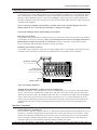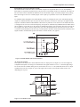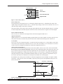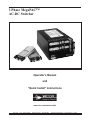
1
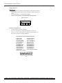
3 Phase MegaPAC™
AC-DC Switcher
Operator’s Manual
and
“Quick Install” Instructions
wer
www.vicr.com/westcor.html
Rev.1/99
Vicor 800-735-6200
Westcor Division 408-522-5280
Applications Engineering 978-749-3524 or -3525
3 Phase MegaPAC Owner’s Manual
3 Phase MegaPAC™
AC-DC Switcher
3 Phase MegaPAC “Quick Install” Instructions
Mounting the 3 Phase MegaPAC
* The 3 Phases MegaPAC can be mounted on any of four sides.
* Use #8-32 or M4 mounting screws. Maximum penetration should not exceed 0.15" (3,8mm).
* A minimum of 2" (5,1cm) clearance must be maintained at either end of the supply in order to insure
proper airflow and cooling.
Output Connections
Power Connections
Installing ring lugs and/or bus bars on output studs:
* The upper stud is Positive and the lower stud is the Return.
* Remove outer nut. Do not remove or loosen inner nut.
* Place ring lug over output stud.
* Replace and tighten outer nut to a maximum torque of 45 lb-in.
Do Not Over-Tighten Nuts.
* Verify all output nuts are properly installed before turning on supply.
DualPAC and DualQPAC Output Connector
Installing power connectors on DualPACs and DualQPACs (J1A and J1B):
* Use Molex mating receptacle #39-01-2060 with #39-00-0039 terminals
provided.
* Pins 1 and 4 are Positive, while pins 2 and 5 are the Return.
* Attach terminals to 18-24 AWG stranded wire using Molex tool #11-01-0197.
Sense Connections
Sense connections must always be made. Failure to connect Sense lines can
cause failure to the unit.
Sense Connector J2:
* Sense connections do not have to be made if the Local Sense option has been
ordered. (An “L” in the ConverterPAC part number means the Local Sense
option has been installed; e.g. M5V/40AL.)
* Use Molex mating receptacle #50-57-9403 with #16-02-0103 terminals provided.
* J2-2 is the +Sense and J2-3 is the -Sense.
* Attach terminals to 22-24 AWG twisted pair wire using Molex tool #11-010208.
* Attach opposite ends of Sense lines to point where regulation is desired.
* Verify that Sense lines are not cross-connected before applying input
power.
4
5
6
1
2
3
J1A & J1B
Pin
1&4 +Vout
2&5 -Vout
3 +Sense
6 -Sense
Sense Connector for Non-QPACs
DualPAC and DualQPAC Output Connector
Sense Connections on QPACs:
* Sense connections do not have to be made if the Local Sense option has been
ordered. (An “L” after the current rating means the Local Sense option has
been installed; e.g., L5V/40AL.)
* Use Molex mating receptacle #39-01-0073 and #39-00-0031 terminals provided.
* J2-7 is the +Sense and J2-6 is the -Sense.
* Attach terminals to 22-28 AWG twisted pair wire using Molex tool
#57005-5000.
* Attach opposite end of Sense lines to point where regulation is desired.
* Verify that Sense lines are not cross-connected before applying input
power.
Pg. 2
Vicor 800-735-6200
Westcor Division 408-522-5280
4
5
6
1
2
3
J1A & J1B
Pin
1&4 +Vout
2&5 -Vout
3 +Sense
6 -Sense
Applications Engineering 978-749-3524 or -3525
Rev. 1/99
3 Phase MegaPAC Owner’s Manual
Sense Connections on DualQPACs:
* Using J1A, J1B, pin 3 is the +Sense and pin 6 is the -Sense.
* Use Molex mating receptacle #39-01-2060 with #39-00-0039 terminals
provided.
* Attach terminals to 18-24 AWG stranded wire using Molex tool #11-010197.
* Attach opposite end of Sense lines to point where regulation is desired.
* Verify that Sense lines are not cross-connected before applying
input power.
J2 Trim Connection
* The J2 remote Trim connection should only be used if the local Trim
option has not been installed. (A “T” or an “F” in the ConverterPAC
part number means the Trim option is installed; e.g. M5V/40AT.)
* Use Molex mating receptacle #50-57-9403 with #16-02-0103 terminals
provided.
* J2-1 provides Trim access.
J2 Trim Connection for DualQPACs
* The J2 Trim connection should only be made if the Trim option has
not been installed. (A “T” or an “F” in the ConverterPAC part number
means the Trim option is installed; e.g. M5V/40AT.)
* Use Molex mating receptacle #39-01-0073 and #39-00-0031 terminals
provided.
* J2-7 is Trim A and J2-6 is Trim B.
* Attach terminals to 22-28 AWG twisted pair wire using Molex tool
#57005-5000.
Output Connector for DualPACs
and DualQPACs
J2 Connector for Non-QPACs
1
2
3
Pin
1 Trim Pin Access
2 +Sense
3 -Sense
J2
J2 Connector for DualQPACs
J2 Connector for DualPACs
DC OK (Power Good) for QPACs
* DC OK is only available as an option and is not always present.
* On ModuPACs, use Molex mating receptacle #39-01-0043 with #3900-0031 terminals provided. On QPACs, use Molex mating receptacle
#39-01-0073 with #39-00-0031 terminals provided.
* Attach terminals to 22-28 AWG stranded wire using Molex tool
#57005-5000.
DC OK (Power Good) for DualQPACs
* DC OK is standard on DualQPACs and gives notice if either output
fails to regulate.
* Use Molex mating receptacle #39-01-0073 and #39-00-0031 terminals
provided.
* Attach terminals to 22-28 AWG twisted pair wire using Molex tool
#57005-5000.
Rev. 1/99
Vicor 800-735-6200
Westcor Division 408-522-5280
J2 Connector for DualQPACs
Applications Engineering 978-749-3524 or -3525
Pg. 3
3 Phase MegaPAC Owner’s Manual
Input Connections
Input Power J1
* Input AC power is applied to terminal block J1 using mating receptacle
AMP #54483-4 with #53892-4 crimp or #54329-1 solder terminals provided.
* Use size 10 AWG wire with soldered terminals.
* A fuse or circuit breaker is recommended in the input line.
Input Connectors
J1
L1
L2
L3
Interface Connections J10
* Use 25 pin D-sub connector provided.
* J10-7 to 11 and J10-20 to 24 are Enable/Disable for slots 1-10.
* J10-16, 17 are Vcc, J10-12 and 15 are Signal Ground, J10-18 is AC
Power OK, and J10-5 is General Shutdown.
J10 INTERFACE CONNECTOR IDENTIFICATION
1 Signal Ground
2 Signal Ground
3 Overtemp. Warning
4 Analog Temperature
5 General Shutdown
6 No Connection
7 Enable/Disable #10
8 Enable/Disable #8
9 Enable/Disable #6
10 Enable/Disable #4
11 Enable/Disable #2
12 Signal Ground
13 Gate In Slot #1 (isolated)
14 Phase Fail Warning
15 Signal Ground
16 Vcc +5 volt, 300 mA
17 Vcc +5 volt, 300 mA
18 Input Power OK
19 Input Power Fail
20 Enable/Disable #9
21 Enable/Disable #7
22 Enable/Disable #5
23 Enable/Disable #3
24 Enable/Disable #1
25 Gate Out Slot #10 (isolated)
1 2 3 4 5 6 7 8 9 10 11 1213
14 15 16 17 18 19 20 21 22 23 24 25
J10
Pg. 4
Vicor 800-735-6200
Westcor Division 408-522-5280
Applications Engineering 978-749-3524 or -3525
Rev. 1/99
3 Phase MegaPAC Owner’s Manual
3 Phase MegaPAC™
AC-DC Switcher
Overview
The 3 Phase MegaPAC is a field-configurable, single or multiple output switcher, providing up to 2000W of output
power and up to 20 regulated, fully isolated outputs. It achieves power density of 4.6 watts per cubic inch. A modular package design allows the user to instantly configure efficient, off-line power supplies. This is accomplished
by inserting up to 10 ConverterPAC output assemblies into a 3-Phase-front-end chassis. Output slots can be filled
with airblocks in anticipation of future power requirements.
A complete power supply is configured by selecting and inserting up to ten slide-in output assemblies called
“ConverterPACs.” ConverterPACs incorporate one or two Vicor DC-DC converters and are available in a wide
array of outputs and power levels. The net result is a power supply that offers the advantages of a custom supply,
but assembled from standard and modular building blocks.
The entire family of MegaPAC power supplies is completely user-configurable. If output requirements change, i.e.,
more power, or a different output voltage is needed, upgrading is easy: simply unlock a single screw and replace
the slide-in ModuPAC assembly with one that has the desired rating. For additional flexibility, ModuPACs can be
connected in parallel to increase output power (booster ModuPACs), or in series for higher voltages. The driver is
to the left of the boosters when looking at the output end of the supply. A user-friendly interface provides control
and output sequencing capability, in addition to useful status indicators. Please consult our Applications
Engineering Department if you have other special requirements.
Standard Features
•
•
•
•
•
•
•
•
•
•
•
•
•
•
Input: 3∅ 208/240 Vac Wye or Delta, or 260-380Vdc
Power Output: 2000W with 3∅ input; 1200W with 1∅ input; 1-20 outputs
Full power to 45°C; half power to 65°C
Active soft-start circuit limits inrush current to 25A peak
Power factor correction to 0.92 PF (3∅ input)
Conducted EMI meets FCC/VDE "A" specifications
AC Power OK and AC Power Fail status signals
Output Sequencing and General Shutdown (Consult Applications Engineering for automatic
sequencing circuitry.)
Inlet air temperature monitor with overtemperature warning and shutdown
Remote Sense capability
Overcurrent protection on all outputs
Overtemperature and output overvoltage protection (except when using VI-J00)
Ride-Through (Holdup) time: >20 ms at full load
Size: 4.9"H x 7.5"W x 15.2"L (124,5mm x 190,5mm x 386,1mm) Extended chassis
Size: 4.9"H x 7.5"W x 12.3"L (124,5mm x 190,5mm x 312,4mm) Regular chassis
Optional Features
• DC OK status signal
• Output voltage adjustment range with built-in potentiometer
• Reversed fan airflow direction
• Industrial-grade screening of output converters
• Hardwired Local Sense
Rev. 1/99
Vicor 800-735-6200
Westcor Division 408-522-5280
Applications Engineering 978-749-3524 or -3525
Pg. 5
3 Phase MegaPAC Owner’s Manual
Technical Description
A 3 Phase MegaPAC is configured by installing ConverterPAC assemblies into a 3-Phase-front-end chassis. The chassis
takes AC input power and performs filtering and rectification functions. The ConverterPACs plug into a high-voltage backplane and provide low-noise, independently regulated and fully isolated outputs.
Input AC mains voltage (L1, L2, L3 and GND) is applied to an agency-approved mating plug. The input current is passed
through an EMI filter designed to meet conducted noise limit "A" specifications of FCC Part 15 and VDE 0871, before it is
passed to a three-phase full-wave bridge rectifier. The rectifier charges storage capacitors and delivers unregulated 300 Vdc
to a backplane after passing through a large choke that improves input power factor. The power factor typically exceeds 0.9
depending upon load, line voltage, frequency and line balance. Inrush current is actively controlled with an IGBT and never
exceeds 25A peak regardless of hot or cold starts.
A housekeeping supply, isolated from the AC input, powers the brushless DC cooling fan and other input monitoring circuits, in addition to providing an auxiliary +5V power source for the user. Excessive input currents caused by loss of a
phase, or excessive output loading in single phase operation, will safely shut down the unit until input power is recycled.
This occurs when the peak input current reaches 25A. An analog temperature monitor is provided, as well as overtemperature shutdown. An active-high TTL compatible, Enable control is included for each ConverterPAC assembly, as well as an
active-low General Shutdown control; the polarities, active-high or active-low, are factory set. 3 Phase MegaPACs can be
safely paralleled with accurate current sharing for high power systems. All interface signals are safety-isolated using a common floating return.
Upon power-up, all outputs are first disabled to limit the inrush current, and to allow the unregulated bus to reach correct
operating levels for ConverterPAC assemblies. The internal housekeeping supply comes up within 500 mS after input
power is applied, and the AC Power OK signal asserts to a TTL "1," indicating the input power is OK. The low voltage
power outputs come up within 10-20 mS after the AC Power OK asserts to a TTL "1." Output ramp-up time from Enable or
General Shutdown is 10-20 mS. Output fall time from Disable is dependent on load, but is typically a few hundred
microseconds.
J1
Input
Power
FCC/VDE
"A" EMI
Filter
3 Phase
Full-Wave
Rectifier
IGBT PFC Choke
Start-up Control
Circuits
Housekeeping
Power Supply
J10
Customer
Interface
Fuse
+P, -P
Output
Power
DC/DC
Converter
Remote Sense,
Trim Interface
Opto-isolated
Control/Status
DC Brushless
Cooling Fan
Power Good
Interface
ConverterPAC (Up to 10)
Figure 1. 3 Phase MegaPAC Architecture
Pg. 6
Vicor 800-735-6200
Westcor Division 408-522-5280
Applications Engineering 978-749-3524 or -3525
Rev. 1/99
3 Phase MegaPAC Owner’s Manual
ConverterPAC Functional Description
ConverterPACs are the family of slide-in output assemblies used in MegaPAC power supplies.
ConverterPACs are interchangeable within a MegaPAC so they can be added, moved, or changed
as necessary. They are also interchangeable between different AC input MegaPAC chassis. A
ConverterPAC removed from a Mini MegaPAC could be used in a 4kW MegaPAC, for example.
ConverterPACs can be selected with a variety of options and in voltages from 2 to 95 Vdc.
+
VI-200
_
Figure 2. ModuPAC
UniPAC
The UniPAC output assembly consists of a VI-900 module that converts the unregulated high voltage bus to the desired regulated output voltage. UniPACs can provide up to 400W of power.
Multiple UniPACs can be paralleled together for higher power. UniPACs are fused with a PC-Tron,
DC-rated, fast acting fuse. The output from a UniPAC comes directly from the VI-900 module and
has no output filtering. A DC Power Good LED is standard and an optional DC Power Good signal is available. Local Sense and Trim options are also available. If the Trim option is not selected, the output voltage can be trimmed using an external circuit and the Trim pin available on the
Sense connector. UniPACs have OCP, which automatically recovers when the overcurrent condition is removed. OVP and OTP are latching functions that require the AC power to be recycled.
+
VI-900
_
Figure 3. UniPAC
VI-J00
DualPAC
This output assembly consists of two VI-J00 DC to DC converters that convert the unregulated high
voltage bus to the desired regulated output voltages. Each output on a DualPAC can provide up to
100 watts of power and are fused with a single PC-Tron, DC-rated, fast-acting fuse. A passive LC
filter is used to reduce output ripple/noise down to 1% typical, and 2% maximum peak-to-peak
from 10% to 100% of rated load. An optional output voltage Trim potentiometer can be specified.
DC Power Good signal is not available. The DualPAC contains overcurrent protection, which
recovers automatically when the overcurrent condition is removed. Overvoltage and overtemperature protection are not available.
VI-J00
Figure 3. DualPAC
+
VI-J00
_
Figure 4. JuniorPAC
+
VI-J00
RAM
_
Figure 5. RAMPAC
Rev. 1/99
ModuPAC
The ModuPAC output assembly consists of a VI-200 DC to DC converter that converts the unregulated high voltage bus to the desired regulated output voltage. Each ModuPAC can provide up to
200 watts of power. Multiple ModuPACs can be paralleled in a driver-booster configuration to provide more power. ModuPACs are fused with a PC-Tron, DC-rated, fast-acting fuse. A passive LC
filter is used to reduce output ripple/noise down to 1% typical, and 2% maximum peak-to-peak
from 10% to 100% of rated load. An optional DC Power Good signal, or output voltage Trim potentiometer can be specified. The ModuPAC contains overvoltage protection (OVP), overcurrent protection (OCP), and overtemperature protection (OTP). The OCP has automatic recovery when the
overcurrent condition is removed. The OVP and OTP are latching functions and require recycling
of the AC input power to restart.
JuniorPAC
The JuniorPAC consists of one VI-J00 DC to DC converter that converts the unregulated high voltage bus to the desired regulated output voltage. JuniorPACs can provide up to 100 watts of output
power and are fused with a single PC-Tron, DC-rated, fast-acting fuse. A passive LC filter is used
to reduce output ripple/noise down to 1% typical, and 2% maximum peak-to-peak from 10% to
100% of rated load. An optional DC Power Good signal, or output voltage Trim potentiometer can
be specified. The JuniorPAC contains output overcurrent protection, which recovers automatically
when the overcurrent condition is removed. Overvoltage and overtemperature protection are not
available.
RAMPAC
This output assembly consists of a VI-J00 DC to DC converter with a Ripple Attenuator Module
(RAM) and is designed for applications requiring low output ripple/noise. The RAMPAC can attenuate the ripple/noise down to 10 mV peak-to-peak over a 20 MHz bandwidth from 10% to 100%
of rated load of the converter. Each RAMPAC can provide up to 100 watts of output power, and
outputs from 5V to 50V are available. An optional DC Power Good signal, or output voltage Trim
potentiometer can be specified. The RAMPAC contains output overcurrent protection, which
recovers automatically when the overcurrent condition is removed. Overvoltage and overtemperature protection are not available.
Vicor 800-735-6200
Westcor Division 408-522-5280
Applications Engineering 978-749-3524 or -3525
Pg. 7
3 Phase MegaPAC Owner’s Manual
BatPAC
The BatPAC output assembly consists of a VI-200 BatMod current source that converts the unregulated high voltage bus to the desired regulated output voltage. The converter is fused with a PCTron, DC-rated, fast-acting fuse. The BatPAC is a 200 watt programmable current source that can
be configured as a battery charger. Overvoltage and overtemperature protection are not available.
Maximum current and voltage settings are controlled using potentiometers that come as a standard
feature, or through Trim pin access as an option. BatPACs are available for 12V, 24V and 48V battery systems.
QPAC
The QPAC output assembly consists of a VI-200 or VI-900 DC to DC converter that converts the
unregulated high voltage bus to the desired regulated output voltage. Each VI-200 QPAC can provide up to 200 watts of output power, and booster QPACs can be added in parallel for more power.
Each VI-900 QPAC can provide up to 400 watts of output power and slave QPACs can be added in
parallel for more power. QPACs are fused with a PC-Tron, DC-rated, fast-acting fuse. An active
preload ensures the DC to DC converter operates in its highest noise performance range. As the load
on the module increases, the preload removes itself from the circuit. Ripple and common mode
noise filters on the output reduce ripple under any load condition to 10 mV p-p or 0.15%, whichever is greater. QPACs using the VI-200 module have an optional DC OK TTL signal. QPACs using
the VI-900 module have a DC OK LED as a standard feature. An optional DC OK TTL signal is
also available. All QPACs can be ordered with an optional trimpot for adjusting the output voltage.
If the trimpot option is not selected, the customer has access to the Trim pin on the module and can
adjust the output voltage using an external circuit. All QPACs have overcurrent protection with
automatic recovery when the overcurrent condition is removed. OVP and OTP are latching functions and require recycling of the AC input power to restart. QPACs can only be ordered in the
extended length 3 Phase and 4kW MegaPACs.
DualQPAC
The DualQPAC output assembly consists of two VI-J00 DC to DC converters that provide two isolated output voltages. DualQPACs can provide up to 100 watts of output power from each output.
DualQPACs are fused with a PC-Tron, DC-rated, fast-acting fuse. An active preload ensures the DC
to DC converters operate in their highest noise performance range. As the load on the module
increases, the preload removes itself from the circuit. Ripple and common mode noise filters on the
output reduce ripple under any load condition to 10 mV p-p or 0.15%, whichever is greater. On
DualQPACs, the customer has access to the Trim pin on the module and can adjust the output voltage using an external circuit. DualQPACs have overcurrent protection with automatic recovery
when the overcurrent condition is removed. Power good is standard and gives notice if either output fails to regulate. OVP and OTP are not available. DualQPACs can only be ordered in the extended length 3 Phase and 4kW MegaPACs.
+
VI-200
Figure 7. BatPAC
VI-200 or
VI-900
Figure 7. QPAC
VI-J00
VI-J00
Figure 8. DualQPAC
ConverterPAC Feature Summary
ConverterPAC
ModuPAC
UniPAC
DualPAC
JuniorPAC
RAMPAC
BatPAC
QPAC
DualQPAC
OVP
OCP
OTP
OVP
Std
Std
N/A
N/A
N/A
N/A
Std
N/A
OCP
Std
Std
Std
Std
Std
Std
Std
Std
OTP
Std
Std
N/A
N/A
N/A
N/A
Std
N/A
Overvoltage Protection (latching)
Overcurrent Protection (auto-recovery)
Overtemperature Protection (latching)
RS
Std
Std
Std
Std
Std
N/A
Std
Std
LS
Opt
Opt
Opt
Opt
Opt
N/A
Opt
Opt
PG
Opt
Opt
N/A
Opt
Opt
N/A
Opt
Std
TrimPot
Opt
Opt
Opt
Opt
Opt
Std
Opt
N/A
RS
LS
PG
Remote Sense
Local Sense
Power Good (DC OK TTL Signal)
Table 1. Summary of ConverterPAC Features
Pg. 8
Vicor 800-735-6200
Westcor Division 408-522-5280
Applications Engineering 978-749-3524 or -3525
Rev. 1/99
_
3 Phase MegaPAC Owner’s Manual
Configuring and Reconfiguring MegaPACs
ConverterPACs can be easily added, replaced, or moved by sliding the assemblies in or out of a MegaPAC chassis.
Most ConverterPACs are driver ModuPACs and can be inserted into any available slot. For outputs greater than
200 watts, a driver ModuPAC and one or more booster ModuPACs will be used. Arrays of drivers and boosters
should be configured so all boosters are placed in the slots to the immediate right of the driver when looking at the
output end of the MegaPAC.
Prior to removing or installing ConverterPACs, you must remove power from the MegaPAC and wait 5
minutes. Failure to do so can result in personal injury or damage to the supply.
Take standard ESD precautions when handling ConverterPACs.
Removing ConverterPACs
ConverterPACs can be removed by loosening the captive screw at the base. Once this screw has been loosened, the
ConverterPAC will slide out of the chassis. Once a ConverterPAC has been removed, the empty slot MUST be
filled with either another ConverterPAC or an airblock. If the slot is left empty, it will provide an airflow
escape, significantly degrade thermal performance, and can cause failure.
Installing ConverterPACs as Drivers
ConverterPACs can be installed in empty slots by simply sliding in the new ConverterPAC and securing the screw
at the base. Power and interface connections can be made after the ConverterPAC has been installed.
Bus Bars for Paralleling
Loosen screw to
remove ConverterPAC
1
Driver
2
3
4
5
6
7
8
9
10
L1 L2 L3
Boosters: Slots 2, 3, 4
Figure 9. Paralleling ModuPACs
Installing Booster ModuPACs or QPACs to Increase Output Power
ModuPACs and QPACs can be paralleled for more power. Additional power to an output is obtained by connecting one or more boosters in parallel with a single driver. The driver can be placed in any open slot. All boosters
should be inserted in the slots to the immediate right of the driver as viewed from the output end of the MegaPAC.
Figure 9 shows a driver placed in slot #1 and 3 boosters placed in slot #s 2 to 4. After inserting the driver and
boosters, they are paralleled using bus bars across the positive and negative output studs. Drivers should not be
paralleled with each other. For help in identifying boosters and drivers, refer to the section on MegaPAC Part
Numbers.
Interface Connections
Chassis Input Power Terminals (J1)
Input AC power is applied to a plug-in connector, J1, that accepts soldered terminals with a maximum wire size of
10 AWG. For operation on high voltage DC input, input power can be connected to any two input lines. A faultclearing device should be installed at the input of the unit. A user-accessible input fuse is not present within the
unit. For an output of 2000W with operation on 208 Vac, 3∅ input, a 20A slow-blow fuse in each input line is
acceptable. Input power cables should be shielded to minimize radiated noise effects.
Rev. 1/99
Vicor 800-735-6200
Westcor Division 408-522-5280
Applications Engineering 978-749-3524 or -3525
Pg. 9
3 Phase MegaPAC Owner’s Manual
Input Connectors
J1
L1
L2
L3
Figure 10. Input Panel Connector
Output Power Connections (+P, -P for Single Output, or J1A/J1B for Dual Outputs)
For single output ConverterPACs, these terminals are two 1/4-20 plated steel studs. The upper stud is positive with
respect to the lower stud. For dual output ConverterPACs, there is a 6-pin Molex connector for each output. J1A
pins 1 and 4 are the +Output, and J1A pins 2 and 5 are the -Output. Pins 3 and 6 are duplicates of the Remote
Sense terminals present on J2A and J2B. Use appropriate wire size rated to handle the full output current, including short circuit levels. Avoid large current loops in output cables; run power and return cables next to one another
to minimize inductive effects. All outputs are isolated and can provide positive or negative outputs.
Output +/-Sense Connections (J2 for Single Output, or J2A/J2B for Dual Outputs)
Although all outputs are open-Sense protected, the +/-Sense terminals MUST be connected to their respective outputs before the 3 Phase MegaPAC is powered up. Regardless of the output polarity configured, the +Sense should
always connect to the +Power output. The -Sense connects to the -Power output. Sense connections are not
required on booster ConverterPACs, BatPACs, or if the Local Sense option is specified. Sense pins can be accessed
on J1A/J1B or J2A/J2B on dual output units.
Signal Ground (J10-1, 2, 12, 15)
Signal Ground (see Figure 11) is an isolated ground reference for all J10 interface signals, and can be used for
ConverterPAC output status signals such as Power Good. This is not the same as Earth Ground on input power
connector J1.
J10 INTERFACE CONNECTOR IDENTIFICATION
1 Signal Ground
2 Signal Ground
3 Overtemp. Warning
4 Analog Temperature
5 General Shutdown
6 No Connection
7 Enable/Disable #10
8 Enable/Disable #8
9 Enable/Disable #6
10 Enable/Disable #4
11 Enable/Disable #2
12 Signal Ground
13 Gate In Slot #1 (isolated)
14 Phase Fail Warning
15 Signal Ground
16 Vcc +5 volt, 300 mA
17 Vcc +5 volt, 300 mA
18 Input Power OK
19 Input Power Fail
20 Enable/Disable #9
21 Enable/Disable #7
22 Enable/Disable #5
23 Enable/Disable #3
24 Enable/Disable #1
25 Gate Out Slot #10 (isolated)
1 2 3 4 5 6 7 8 9 10 11 1213
14 15 16 17 18 19 20 21 22 23 24 25
J10
Figure 11. Interface Connector (J10)
Pg. 10
Vicor 800-735-6200
Westcor Division 408-522-5280
Applications Engineering 978-749-3524 or -3525
Rev. 1/99
3 Phase MegaPAC Owner’s Manual
Enable/Disable and General Shutdown (GSD)
The Enable/Disable control lines allow ConverterPAC outputs to be sequenced either on or off. For DualPACs,
both outputs are sequenced. In parallel arrays, only the driver ConverterPAC needs to be sequenced. The GSD control line on J10-5 allows simultaneous shutdown of all ConverterPAC outputs. An internal jumper selects polarity,
either active-high or active-low. Another jumper selects a pull-up or pull-down source for the HCMOS control
inputs.
For standard 3 Phase MegaPACs, the Enable/Disable controls are configured as active-low with internal pull-up;
outputs are enabled when these pins are open-circuited or allowed to exceed 4.5V with respect to Signal Ground.
Outputs are disabled when the Enable/Disable control lines are pulled low to less than 0.7V. The GSD control line
is configured to be active-low with internal pull-up; all outputs are simultaneously inhibited when the GSD control
line is pulled low to less than 0.7V. All outputs are enabled when GSD is open circuited or allowed to exceed 4.5V.
Do not apply more than 5V to these inputs at any time. The E/D and GSD circuits will sink up to 0.6 mA. If driven from an electromechanical switch or relay, a small capacitor should be connected between the control line and
Signal Ground to eliminate latch-up due to the effects of switch bounce (1µF, typical).
Figure 12. Enable/Disable and General Shutdown
AC Power OK (J10-18)
This signal on J10-18 provides a status indication of the AC input power (see Figure 13). It is active high, TTL
compatible and capable of sourcing 10 mA maximum. This signal switches to a TTL “1” when the high voltage
bus exceeds low-line condition during turn-on, and switches to a TTL “0” 3 ms (minimum) before loss of output
regulation due to the loss of input AC power. This signal can be used to warn external control circuits of an
impending loss of power.
Figure 13. AC OK/Power Fail
Rev. 1/99
Vicor 800-735-6200
Westcor Division 408-522-5280
Applications Engineering 978-749-3524 or -3525
Pg. 11
3 Phase MegaPAC Owner’s Manual
AC Power Fail (J10-19)
J10-19 is the inverse of AC Power OK, and goes to a TTL “1” when the input AC power is not OK. It is capable
of sourcing 10 mA maximum. The fan out is 20.
Phase Fail (Input Overcurrent) (J10-14)
J10-14 is a TTL level active-high signal that is asserted when the peak input current reaches 30A due to the loss of
an input phase, or severe line imbalance. This occurs when one input phase is lost with approximately 1400W output loading. Maximum current that can be sourced is 10 mA.
Overtemperature Warning (J10-3)
J10-3 is a signal that asserts a TTL level "1" if the air temperature exceeds the following factory set levels. The
warning trip point is 65°C to 76°C, typically, and recovery point is 60°C to 71°C, typically.
Overtemperature Shutdown
If the inlet ambient air temperature exceeds the following factory set levels, the outputs are disabled. The shutdown trip point is 70°C to 81°C, typically, and recovery point is 40°C to 48°C, typically.
Analog Temperature Monitor (J10-4)
This signal on J10-4, referenced to SignalGround, provides an analog DC voltage output between 0V and 10V that
represents the air temperature of 0°C to 100°C respectively inside the power supply. The inlet air temperataure is
monitored close to the fan.
Gate IN/Gate OUT (J10-13, 25)
The Gate IN and Gate OUT signals are used for paralleling 3 Phase MegaPACs for power expansion. The Gate
OUT signal, J10-25, of the driver 3 Phase MegaPAC should be connected to the Gate IN, J10-13, of the Booster 3
Phase MegaPAC; J10 signal ground of the driver 3 Phase MegaPAC also needs to be connected to J10 signal
ground of the booster 3 Phase MegaPAC.
The driver 3 Phase MegaPAC (ModuPAC, slot #10) generates the Gate OUT signal and sends it to the booster 3
Phase MegaPAC (ModuPAC, slot #1). Vicor's zero-current-switching booster technology provides for accurate,
dynamic power sharing within arrays, without the need for trimming, module "matching" or external components.
Auxiliary Vcc +5V/0.3A (J10-16, 17)
The Vcc on J10-16, 17 is an auxiliary 5V regulated power source (see Figure 14 and Connector Pin Identification
of page 16). It is +5 Vdc +/–5% with respect to Signal Ground and can supply 300 mA maximum. It is short circuit proof, but if shorted all outputs will shut down through the Enable/Disable circuitry. The Auxiliary Vcc typically powers user circuitry or is used with the Power Good circuitry to provide a pull-up reference for the outputs
of the DC Power Good circuit on a ModuPAC. If used for this purpose, a J10 Signal Ground must also be connected to the J3-1 Signal Ground pin of the ModuPAC.
+5V/300 mA
78M05
J10
16, 17 Auxiliary Vcc
0.1 µF
1, 2, 12, 15 Signal Ground
Figure 14. Auxiliary Vcc
Pg. 12
Vicor 800-735-6200
Westcor Division 408-522-5280
Applications Engineering 978-749-3524 or -3525
Rev. 1/99
3 Phase MegaPAC Owner’s Manual
ConverterPAC
2.49K
2.49K
10K
J3
4
Vcc In
3
Power Good
2
Power Good Inverted
2N2222
1
Signal Ground
Figure 15. Power Good and Vcc
Power Good (J3-3)
The optional Power Good signal on J3-3 is referenced to Signal Ground on J3-1, and indicates the status of the
output voltage. This signal is asserted a TTL “1” when the output voltage is above 95% of nominal. It is a TTL “0”
when the output voltage is below 85% of nominal.
If the Trim option is also used, the Power Good trip points DO NOT track with the trimmed voltage. It is possible
to trim the output below the fixed setpoints of the Power Good circuit and cause a negative Power Good signal.
Power Good Inverted (J3-2)
This is the inverse of the Power Good signal and is referenced to Signal Ground on J3-1.
Signal Ground (J3-1)
Signal Ground on J3-1 is an isolated secondary ground reference for J3 status signals. It is used to provide a reference point for the Power Good circuitry and is not the same as Earth Ground on input power connector J1.
Vcc In (J3-4)
The Vcc In on J3-4 is an input that requires +5V either from the J10 Auxiliary Vcc, or from another source. Input
current to this pin is limited by an internal resistor to 3 mA. If the J10 Auxiliary Vcc is connected to Vcc In on J34, then at least one J10 Signal Ground must be connected to Signal Ground on J3-1.
+Sense/–Sense (J2-2 and J2-3)
The +Sense on J2-2 should be connected to the +Power Out, and the –Sense on J2-3 to the –Power Out terminal.
Do not reverse or leave the Sense pins open. Sense pins can be terminated locally at the output of the power supply, in which case the power supply will provide regulation at the output terminals. The voltage appearing at the
load may drop slightly due to voltage drop in the power cables. If it is necessary to compensate for voltage drop
along the output power cables, this termination should be made close to the output load. Compensation of up to
0.5V (0.25V per lead) can be obtained. Use twisted pair 22-24 AWG wire for this purpose.
For DualPACs, the +Sense pins are available on connectors designated as J2A-2 and J2B-2 for outputs A and B,
respectively. –Sense pins are on J2A-3 and J2B-3, respectively. These pins are also duplicated on the power connectors J1A and J1B.
+P +Out
(Local Sense)
(Remote Sense)
J2-2 +Sense
Load
J2-3 -Sense
-P -Out
Use 22-24 AWG Twisted Pair Wires
Figure 16. Sense Leads
Rev. 1/99
Vicor 800-735-6200
Westcor Division 408-522-5280
Applications Engineering 978-749-3524 or -3525
Pg. 13
3 Phase MegaPAC Owner’s Manual
External Trim (J2-1)
Output voltage can be trimmed using an optional factory-installed trim potentiometer or with the Trim pin (see
Figure 18). The Trim potentiometer is located on the ConverterPAC. If the Trim potentiometer has not been
ordered, the Trim pin must be used. When using the Trim pin, the Trim limits are determined by the DC/DC converter used on the ConverterPAC. Maximum Trim ranges are 10% above the nominal converter voltage and 50%
below the nominal converter voltage.
The Trim pin on J2 can be used to control the output voltage. It is referenced to the -Sense pin on J2 and can be
controlled by either a resistor network or an external voltage source. To increase an output voltage above its nominal, it is necessary to increase the voltage at the Trim pin above the internal reference voltage (Vref). The reverse
is true to decrease an output voltage.
Note: Converters are sometimes pretrimmed at the factory if a nonstandard output voltage is requested. Standard
voltages include 2V, 3.3V, 5V, 12V, 15V, 24V, 28V, and 48V. If using a nonstandard voltage, or if a ConverterPAC
is ordered with a Trim option, the resistor calculations will differ from those below. Please consult the factory for
assistance.
OUTPUT MODULE
VI-200/VI-J00 ≥3.3V
VI-200/VI-J00 <3.3V
2nd Generation (Pre-Configured)
2nd Generation (Customer Configured)
RTH
10.0 kΩ
3.88kΩ
1.0 kΩ
Consult Factory
Vref
2.50V
0.97V
1.23V
1.23V
Table 2. Module Internal Reference Voltages and Thevenin Resistances.
(Remote Sense)
+Out
R1
10-300Ω
+Sense
R8
R2
To Error
Amplifier
Trim
+ R
TH R5
V1
-
VRef
R6
R3
-Sense
R4
20-200Ω
R7
+
V2
-
Load
-Out
Use 22-24 AWG Twisted Pair Wires
Figure 17. External Trim
Pg. 14
Vicor 800-735-6200
Westcor Division 408-522-5280
Applications Engineering 978-749-3524 or -3525
Rev. 1/99
3 Phase MegaPAC Owner’s Manual
Example:
±10% Trim adjust on a 12V nominal output.
Figure 17 shows a typical variable Trim circuit. Using a 10k Trimpot (R7), the resistor values for R6 and R8 can be calculated as follows:
V1= Vref + 10% = 2.75V
Given: Vref = 2.5V (see Table 2)
IR5 = (2.75V - Vref)/RTH = (2.75V - 2.5V)/10kΩ = 25µA
Setting the bottom limit:
VR6 = 2.5V - 10% = 2.25V
And since IR5 = IR6 = 25µA,
R6 = VR6/IR6= 2.25V/25µA = 90kΩ
V2 = V1 + VR6 = 2.75V + 2.25V = 5V
IR7 = V2/R7 = 5V/10kΩ = 500µA
IR8 = IR7 + IR6 = 525µA
VR8 = (Vnom +10%) - V2 = 13.2V - 5V = 8.2V
Given: Vnom = 12V
R8 = VR8/IR8 = 8.2V/525µA = 15.62kΩ
Using the above resistor combination, a 12V output can be trimmed externally up to 13.2V and down to 10.8V. For further
information on external trimming, refer to Chapter 5 of the Applications Manual or consult the factory for assistance.
CONSULT APPLICATIONS ENGINEERING WHEN TRIMMING OUTPUTS BELOW 5V.
Rev. 1/99
Vicor 800-735-6200
Westcor Division 408-522-5280
Applications Engineering 978-749-3524 or -3525
Pg. 15
3 Phase MegaPAC Owner’s Manual
Mechanical Considerations
The 3 Phase MegaPAC can be mounted on any of four surfaces using standard 8-32/M4 screws. The chassis comes
with four mounting points on each surface; maximum allowable torque is 20 lb-in. The maximum penetration is
0.15 in. (3,8mm).
When selecting a mounting location and orientation, the unit should be positioned so air flow is not restricted.
Maintain a 2" minimum clearance at both ends of the 3 Phase MegaPAC and route all cables so airflow is not
obstructed. The standard unit draws air in at the fan side/AC input side and exhausts air out the load side. If airflow
ducting is used, use caution, as sharp turns could present back pressure to the 3 Phase MegaPAC. The fan moves
approximately 30 CFM of air.
Avoid excessive bending of output power cables after they are connected to the 3 Phase MegaPAC. For high-current outputs, use cable ties to support heavy cables in order to minimize mechanical stress on output studs. Be careful not to short-out to neighboring output studs. The 3 Phase MegaPAC is supplied with serrated, flanged hex-nuts
on all output studs, so Loc-tite® or lock washers are not required. The maximum torque recommended on flanged
nuts is 45 lb-in. Never loosen the inner nut on a ConverterPAC. This nut supports the hardware inside the
ConverterPAC and is factory torqued.
Avoid applications in which the unit is exposed to excessive shock or vibration levels. In such applications, a shock
absorption mounting design is required.
MegaPAC Do’s and Don’ts
•
•
•
•
•
•
•
•
•
•
•
•
•
•
Pg. 16
Do not leave ConverterPAC Sense lines open. Always terminate them locally or at the load. Use twisted
pair 22-24 AWG wire.
Always fill all output slots of the MegaPAC. If a slot is not filled with a ConverterPAC, it should be
filled with an airblock. Failure to do so can result in overheating and damage to the power supply.
Do not unplug ConverterPACs while input power is applied. They are not designed for hot-plug
applications.
Do not restrict airflow to the unit. The cooling fan draws air into the unit and forces it out at the output
power terminals.
For power expansion use booster ModuPACs. Viewing the unit from the output terminal side, always insert
boosters to the right side of the driver.
For booster arrays, do not remove busbars.
Always ensure that output hex-nuts are properly torqued before applying power to supply.
Run the output (+/–) power cables next to each other to minimize inductance.
Wait 5 minutes after shutting off power before inserting or removing ConverterPACs.
Do not attempt to repair or modify the power supply in any manner other than the exchange of ConverterPACs
as described in this manual.
Insert proper fault protection at power supply input terminals (i.e., a fuse).
Use proper size wires to avoid overheating and excessive voltage drop.
Never loosen the inner nut on a ConverterPAC.
Verify output nuts are tight before powering up.
Vicor 800-735-6200
Westcor Division 408-522-5280
Applications Engineering 978-749-3524 or -3525
Rev. 1/99
3 Phase MegaPAC Owner’s Manual
ConverterPAC Output and Connector Pin Identification
ModuPAC
JuniorPAC
RAMPAC
Sense Connector
+ Vout
Remote Sense
Output Adjust
Pin
1 Trim Pin Access
2 +Sense
3 -Sense
1
2
3
- Vout
Molex #50-57-9403 housing,
using #16-02-0103 terminals and
22-24 AWG stranded wire. Use
Molex tool #11-01-0208.
J2
DC OK (Power Good)
DC OK (Power Good)
for ModuPACs
Pin
4
3
2
1
4
3
2
1
J3
DualPAC
Output #1 J1B
Vcc In
Power Good
Power Good Inverted
Signal Ground
DualPAC and DualQPAC Output Connector
Remote Sense
Output #1 Adjust
4
5
6
Output #2 J1A
J1A & J1B
1
2
3
Pin
1&4 +Vout
2&5 -Vout
+Sense
3
-Sense
6
Molex #39-01-043 housing
using #39-00-0031 terminals
and 22-28 AWG stranded wires.
Use Molex tool #57005-5000.
Molex #39-01-2060 housing
with #39-00-0039 terminals and
18-24AWG stranded wire. Use
Molex tool #11-01-0197.
Remote Sense
Output #2 Adjust
BatPAC
BatPAC Remote Interface
+ Vout
Pin
4
3
2
1
4
3
2
1
Current Limit Adjust
Voltage Limit Adjust
- Vout
J2
Current Limit Adjust
Voltage Limit Adjust
Current Monitor
- Vout
Molex #39-01-043 housing
using #39-00-0031 terminals
and 22-28 AWG stranded wires.
Use Molex tool #57005-5000.
Remote Interface
QPAC Sense Connector
QPAC
Molex #39-01-0073 housing using
#39-00-0031 terminals and 22-28
AWG stranded wire. Use Molex tool
#57005-5000.
+ V out
Output Adjust
_ V out
Remote Sense
DualQPAC
Output #1 J1B
DualPAC and DualQPAC Output Connector
Remote Sense
4
5
6
Output #2 J1A
Rev. 1/99
Vicor 800-735-6200
1
2
3
J1A & J1B
Westcor Division 408-522-5280
Pin
1&4 +Vout
2&5 -Vout
+Sense
3
-Sense
6
Molex #39-01-2060 housing
with #39-00-0039 terminals and
18-24AWG stranded wire. Use
Molex tool #11-01-0197.
Applications Engineering 978-749-3524 or -3525
Pg. 17
3 Phase MegaPAC Owner’s Manual
3 Phase MegaPAC Mechanical Drawings
TOP VIEW - EXTENDED LENGTH
TOP VIEW - REGULAR LENGTH
2.25 (57,2mm)
DO NOT LOOSEN OR
TIGHTEN INNER NUTS
.50 (12,7mm)
BOTTOM SIDE
4 MOUNTING HOLES EACH SURFACE
(M4/#8-32, .15 (3,8mm) MAX. PENETRATION)
DO NOT LOOSEN OR
TIGHTEN INNER NUTS
.50 (12,7mm)
(BOTTOM SIDE)
5.10
(129,5mm)
(TOP SIDE)
7.50 (190,5mm)
1/4 - 20 ZINC PLATED
STEEL, SERRATED
FLANGED NUTS
45 LB-IN MAX.
6.50
(165,1mm)
(BOTTOM SIDE)
7.50 (190,5mm)
6.75 (171,5mm)
(TOP & BOTTOM SIDE)
(TOP & BOTTOM SIDE)
6.50
(165,1mm)
(BOTTOM SIDE)
4 MOUNTING HOLES EACH SURFACE
(M4/#8-32, .15 (3,8mm) MAX. PENETRATION)
1/4 - 20 ZINC PLATED
STEEL, SERRATED
FLANGED NUTS
45 LB-IN MAX.
5.10
(129,5mm)
(TOP SIDE)
1.20
(30,5mm)
1.20
(3,5mm)
2.25
(57,2mm)
(TOP SIDE)
6.75 (171,5mm)
SIDE VIEW - REGULAR LENGTH
6.75
(171,5mm)
2.25 (57,2mm)
SIDE VIEW - EXTENDED LENGTH
OUTPUT
OUTPUT
OUTPUT RETURN
4.00
(101,6mm)
4.00
(101,6mm)
OUTPUT RETURN
.65 (16,5mm)
.65 (16,5mm)
.15 (3,8mm)
2.25
(57,2mm)
6.75 (171,5mm)
11.95 (303,5mm)
12.28 (311,2mm)
11.95 (303,5mm)
.15
(3,8mm)
15.17 (385,3mm)
REAR VIEW
7.50 (190,5mm)
J10 INTERFACE CONNECTOR IDENTIFICATION
TOP
1 Signal Ground
2 Signal Ground
3 Overtemp. Warning
4 Analog Temperature
5 General Shutdown
6 No Connection
7 Enable/Disable #10
8 Enable/Disable #8
9 Enable/Disable #6
10 Enable/Disable #4
11 Enable/Disable #2
12 Signal Ground
13 Gate In Slot #1 (isolated)
#4-40 CAPTIVE SCREWS
TO SECURE/REMOVE
CONVERTERPACS,
10 PLACES
4.90
(124,5mm)
L1 L2 L3
INPUT POWER
STATUS/CONTROL
SIGNALS J10
CONNECTIONS J1
14 Phase Fail Warning
15 Signal Ground
16 Vcc +5 volt, 300 mA
17 Vcc +5 volt, 300 mA
18 Input Power OK
19 Input Power Fail
20 Enable/Disable #9
21 Enable/Disable #7
22 Enable/Disable #5
23 Enable/Disable #3
24 Enable/Disable #1
25 Gate Out Slot #10 (isolated)
1 2 3 4 5 6 7 8 9 10 11 1213
14 15 16 17 18 19 20 21 22 23 24 25
Power Derating with Altitude and Temperature
g
p
100.0%
37˚C
Maximum Power
95.0%
38˚C
39˚C
40˚C
90.0%
41˚C
85.0%
42˚C
43˚C
44˚C
80.0%
45˚C
00
00
,0
15
00
,0
,0
14
13
00
,0
12
00
,0
11
0
00
,0
10
0
00
9,
0
00
8,
0
00
7,
0
00
6,
0
00
5,
0
00
4,
0
00
3,
0
00
2,
1,
00
0
75.0%
Altitude (ft.)
Pg. 18
Vicor 800-735-6200
Westcor Division 408-522-5280
Applications Engineering 978-749-3524 or -3525
Rev. 1/99
3 Phase MegaPAC Owner’s Manual
Output Power Derating
Rev. 1/99
Vicor 800-735-6200
Westcor Division 408-522-5280
Applications Engineering 978-749-3524 or -3525
Pg. 19
3 Phase MegaPAC Owner’s Manual
Specifications
Input Characteristics
Input Voltage
208/240 Vac, 3 Phase, 4 Wire
180-264 Vac, 1 Phase (47-500Hz)
260-380 Vdc
Power Factor
.92 (3 Phase operation)
Line Regulation
0.2% max. from 10% to full load
Inrush Current
25A rms @ 230 Vac
Ride Through Time
>20 ms at nominal line, full load
Power Fail
>3 ms warning
Conducted EMI
VDE and FCC Class A
47 - 63 Hz
Transient Surge
(Common Mode and Normal Mode)
EN/IEC 1000-4-2 Level 4
EN/IEC 1000-4-5 Level 3
Output Characteristics
Load Regulation
0.2% max. from 10% to 100% load
0.5% max. from 0% to 10% load
Setpoint Accuracy
1% for standard voltages
2% for special or adjustable voltages
Ripple and Noise
Std. outputs: 2% or 100 mV p-p max., whichever is greater, 10% min. load
VXI options ( <24V outputs): 50 mV p-p max for outputs <15 Vdc;
150 mV p-p max. for 24 Vdc outputs
QPAC, DualQPAC, JuniorPAC, RAMPAC: <10mV p-p max.
Overcurrent Protection
105-130% > 5V outputs & DualPACs, JuniorPACs, RAMPACs, DualQPACS,
JuniorQPACs
30-125% < 5V outputs
Overvoltage Protection
115- 135% ModuPACs and QPACs only
Efficiency
82% typical
Output Power
2000W at 45°C (3 Phase); 1200W at 45°C (1 Phase)
Environmental Characteristics
Storage Temperature
-40°C to 65°C
Operating Temperature
C-grade: 0°C to 45°C full power, 0°C to 65°C half power
I-grade: -20°C to +45°C full power, -20°C to +65°C half power
Safety Approvals
UL 1950 (2nd), CSA C22.2 No. 234, IEC 950, EN 60 950
Product Weights
17 lbs (7,72 kg) fully configured
0.7 lbs (0,32 kg) ConverterPAC
Warranty
2 years
Pg. 20
Vicor 800-735-6200
Westcor Division 408-522-5280
Applications Engineering 978-749-3524 or -3525
Rev. 1/99
3 Phase MegaPAC Owner’s Manual
Part Numbering
PFC Mini
PMx1-x2x3-xxx
x1
x2
x3
xxx
Number of outputs
Number of VI-200 and VI-J00 modules
Number of VI-900 and VI-800 modules
Sequential number assigned by Westcor
PFC MegaPAC
M P x A - 7 x B xxx
e g. MP 5- 7 8143
xA
xB
xxx
No. of outputs
No. of modules
Assigned by Westcor
A/R MegaPAC
M P x A - 9 x B xxx
e g. MP 5- 9 8143
xA
xB
xxx
No. of outputs
No. of modules
Assigned by Westcor
Mini MegaPAC
M M x A - 1 x B x xx
e g. MM4- 1 411 2
xA
xB
xxx
No. of outputs
No. of modules
Assigned by Westcor
3Ø MegaPAC
M P x A - 5 x B xxx( - EL)
e g. MP 4- 5 10108
xA
xB
xxx
-EL
No. of outputs
No. of modules
Assigned by Westcor
Option indicating extended length chassis for use with QPACs
4kW MegaPAC
MPxA-4xBxxx (-EL)
eg. MP10-410008
xA
xB
xxx
-EL
No. of outputs
No. of modules
Assigned by Westcor
Option indicating extended length chassis for use with QPACs
DC MegaPAC
M D x A - x C x B xxx
e g. MD2- N 8103
xA
xB
xxx
xC
Number of outputs
Number of modules
Assigned by Westcor
DC input voltage range
0
12 Vdc input (10-20V range)
1
24 Vdc input (21-32V range)
W
24 Vdc input (18-36V range)
2
36 Vdc input (21-56V range)
3
48 Vdc input (42-60V range)
N
48 Vdc input (36-76V range)
4
72 Vdc input (55-100V range)
ConverterPAC
xCXx D V/x E Ax F
e g. 3M15V/10A
NM 1 5V/10ADF I L
D15V/6.7A-12V/8.3AT
X
ConverterPAC type
M - ModuPAC
L - QPAC (VI-200)
D - DualPAC
U - UniPAC
J - JuniorPAC
XL - QPAC (VI-900)
R - RAMPAC
LD - DualQPAC (VI-J00)
B - BatPAC
DC input voltage range (only used for DC MegaPAC ConverterPACs)
0
12 Vdc input (10-20V range)
1
24 Vdc input (21-32V range)
W
24 Vdc input (18-36V range)
2
36 Vdc input (21-56V range)
3
48 Vdc input (42-60V range)
N
48 Vdc input (36-76V range)
4
72 Vdc input (55-100V range)
Voltage out
Current out (rounded to 1 decimal point)
Options (See below*). Can be multiple options.
xC
xD
xE
xF
*ConverterPAC Options
B
D
F
F1
F2
F3
F4
F5
F6
F7
F8
F9
I
K
L
Rev. 1/99
Booster module
DC OK or Power Good (N/A on DualPAC)
Full 50-110% output adjustment
50-107.5% output adjustment
50-105% output adjustment
50-102.5% output adjustment
50-100% output adjustment
60-110% output adjustment
70-110% output adjustment
80-110% output adjustment
90-110% output adjustment
100-110% output adjustment
Industrial Grade module
Custom SRF module used
Local Sense
Vicor 800-735-6200
M
R
S
T
T1
T2
T3
T4
T5
T6
V1
V2
V3
W
Z
Westcor Division 408-522-5280
Military Grade module
RAM external
Trimpot removed for external BatPAC adjustment
90-110% output adjustment
90-107.5% output adjustment
90-105% output adjustment
90-102.5% output adjustment
90-100% output adjustment
100-105% output adjustment
100-110% output adjustment
"VXI" low noise (150 mV or less) for 24V outputs
"VXI" low noise (50 mV or less) for outputs < 24V
1% ripple or less for outputs >24V
Westcor Grade module
Other special feature
Applications Engineering 978-749-3524 or -3525
Pg. 21
3 Phase MegaPAC Owner’s Manual
Notes
Pg. 22
Vicor 800-735-6200
Westcor Division 408-522-5280
Applications Engineering 978-749-3524 or -3525
Rev. 1/99
3 Phase MegaPAC Owner’s Manual
Notes
Rev. 1/99
Vicor 800-735-6200
Westcor Division 408-522-5280
Applications Engineering 978-749-3524 or -3525
Pg. 23
Vicor Corporation, Corp. Headquarters
25 Frontage Road
Andover, MA 01810
Tel: 800-735-6200, 978-470-2900
Fax: 978-475-6715
Vicor Corporation
377 E. Butterfield Road
Suite 201
Lombard, IL 60148
Tel: 630-769-8780
Fax: 630-769-8782
Westcor Division
560 Oakmead Parkway
Sunnyvale, CA 94086
Tel: 408-522-5280
Fax: 408-774-5555
Vicor France
Tel: 33-1-3452-1830
Free Phone France Only:
0800 419 419
Fax: 33-1-3452-2830
Vicor Germany
Tel: +49-89-962439-0
Free Phone Germany Only:
0130 18 29 18
Fax: +49-89-962439-39
Vicor Hong Kong
Tel: +852-2956-1782
Fax: +852-2956-0782
Vicor Italy
Tel: +39-02-2247-2326
Free Phone Italy Only:
167-899-677
Fax: +39-02-2247-3166
Vicor Japan Co., Ltd.
Tel: 81-3-5487-3880
Fax: 81-3-5487-3885
Vicor U.K.
Tel: +44-1276-678-222
Free Phone UK Only:
0800-980-8427
Fax: +44-1276-681-269
For more information about this or other Vicor products, or for assistance with component-based power system design,
contact the Vicor office nearest you. Vicor's comprehensive line of power solutions includes modular, high-density DCDC converters and accessory components, configurable power supplies, and custom power systems.
Information furnished by Vicor is believed to be accurate and reliable. However, no responsibility is assumed by Vicor for its use. No license is granted by implication or otherwise under any patent or patent rights of Vicor. Vicor components are not designed to be used in applications, such as life
support systems, wherein a failure or malfunction could result in injury or death. All sales are subject to Vicor's Terms and Conditions of Sale, which
are available upon request.
wer
www.vicr.com/westcor.html