1
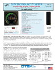
���������
������������������
DIGITAL 31 BAND REAL TIME ANALYZER
Safety Instructions/Consignes de sécurité/Sicherheitsvorkehrungen/Instrucciones de seguridad
WARNING: To reduce the risk of fire or electric shock, do not expose this unit to rain
or moisture. To reduce the hazard of electrical shock, do not remove cover or back.
No user serviceable parts inside. Please refer all servicing to qualified personnel.The
lightning flash with an arrowhead symbol within an equilateral triangle, is intended to
alert the user to the presence of uninsulated "dangerous voltage" within the products
enclosure that may be of sufficient magnitude to constitute a risk of electric shock to
persons. The exclamation point within an equilateral triangle is intended to alert the
user to the presence of important operating and maintenance (servicing) instructions
in the literature accompanying the product.
Important Safety Instructions
1. Please read all instructions before operating the unit.
DO NOT
EXPOSE
THIS EQUIPMENT
2. Keep these instructions
for future
reference.
RAIN
OR
MOISTURE
TO
3. Please heed all safety warnings.
4. Follow manufacturers instructions.
5. Do not use this unit near water or moisture.
6. Clean only with a RISQUE
damp cloth.DE CHOC ELECTRONIQUE
NE PAS
OUVRIR
7. Do not block any of the ventilation
openings.
Install in accordance with the manufacturers instructions.
8. Do not install near any heat sources such as radiators, heat registers, stoves, or
other apparatus (including amplifiers) that produce heat.
9. Do not defeat the safety purpose of the polarized or grounding-type plug. A polarized plug has two blades with one wider than the other. A grounding type plug has
two blades and a third grounding prong. The wide blade or third prong is provided
for your safety. When the provided plug does not fit your outlet, consult an electrician for replacement of the obsolete outlet.
10. Protect the power cord from being walked on and pinched particularly at plugs,
convenience receptacles and at the point at which they exit from the unit.
11. Unplug this unit during lightning storms or when unused for long periods of time.
12. Refer all servicing to qualified personnel. Servicing is required when the unit has
been damaged in any way, such as power supply cord or plug damage, or if liquid
has been spilled or objects have fallen into the unit, the unit has been exposed to
rain or moisture, does not operate normally, or has been dropped.
ATTENTION: Pour éviter tout risque d’électrocution ou d’incendie, ne pas exposer cet
appareil à la pluie ou à l’humidité. Pour éviter tout risque d’électrocution, ne pas ôter le
couvercle ou le dos du boîtier. Cet appareil ne contient aucune pièce remplaçable par
l'utilisateur. Confiez toutes les réparations à un personnel qualifié. Le signe avec un éclair
dans un triangle prévient l’utilisateur de la présence d’une tension dangereuse et non
isolée dans l’appareil. Cette tension constitue un risque d’électrocution. Le signe avec un
point d’exclamation dans un triangle prévient l’utilisateur d’instructions importantes relatives à l’utilisation et à la maintenance du produit.
Consignes de sécurité importantes
1. Veuillez lire toutes les instructions avant d’utiliser l’appareil.
2. Conserver ces instructions pour toute lecture ultérieure.
3. Lisez avec attention toutes les consignes de sécurité.
4. Suivez les instructions du fabricant.
5. Ne pas utiliser cet appareil près d’une source liquide ou dans un lieu humide.
6. Nettoyez l’appareil uniquement avec un tissu humide.
7. Veillez à ne pas obstruer les fentes prévues pour la ventilation de l’appareil. Installez
l’appareil selon les instructions du fabricant.
8. Ne pas installer près d’une source de chaleur (radiateurs, etc.) ou de tout équipement
susceptible de générer de la chaleur (amplificateurs de puissance par exemple).
9. Ne pas retirer la terre du cordon secteur ou de la prise murale. Les fiches canadiennes
avec polarisation (avec une lame plus large) ne doivent pas être modifiées. Si votre
prise murale ne correspond pas au modèle fourni, consultez votre électricien.
10. Protégez le cordon secteur contre tous les dommages possibles (pincement, tension,
torsion,, etc.). Veillez à ce que le cordon secteur soit libre, en particulier à sa sortie du
boîtier.
11. Déconnectez l’appareil du secteur en présence d’orage ou lors de périodes
d’inutilisation prolongées.
12. Consultez un service de réparation qualifié pour tout dysfonctionnement (dommage
sur le cordon secteur, baisse de performances, exposition à la pluie, projection liquide dans l’appareil, introduction d’un objet dans le boîtier, etc.).
ACHTUNG: Um die Gefahr eines Brandes oder Stromschlags zu verringern, sollten
Sie dieses Gerät weder Regen noch Feuchtigkeit aussetzen.Um die Gefahr eines
Stromschlags zu verringern, sollten Sie weder Deckel noch Rückwand des Geräts entfernen. Im Innern befinden sich keine Teile, die vom Anwender gewartet werden können. Überlassen Sie die Wartung qualifiziertem Fachpersonal.Der Blitz mit Pfeilspitze im
gleichseitigen Dreieck soll den Anwender vor nichtisolierter “gefährlicher Spannung”
im Geräteinnern warnen. Diese Spannung kann so hoch sein, dass die Gefahr eines
Stromschlags besteht. Das Ausrufezeichen im gleichseitigen Dreieck soll den Anwender
auf wichtige Bedienungs- und Wartungsanleitungen aufmerksam machen, die im mitgelieferten Informationsmaterial näher beschrieben werden.
Wichtige Sicherheitsvorkehrungen
1. Lesen Sie alle Anleitungen, bevor Sie das Gerät in Betrieb nehmen.
2. Bewahren Sie diese Anleitungen für den späteren Gebrauch gut auf.
PRECAUCION: Para reducir el riesgo de incendios o descargas, no permita que este
aparato quede expuesto a la lluvia o la humedad. Para reducir el riesgo de descarga
eléctrica, nunca quite la tapa ni el chasis. Dentro del aparato no hay piezas susceptibles
de ser reparadas por el usuario. Dirija cualquier reparación al servicio técnico oficial. El
símbolo del relámpago dentro del triángulo equilátero pretende advertir al usuario de
la presencia de “voltajes peligrosos” no aislados dentro de la carcasa del producto, que
pueden ser de la magnitud suficiente como para constituir un riesgo de descarga eléctrica a las personas. El símbolo de exclamación dentro del triángulo equilátero quiere
advertirle de la existencia de importantes instrucciones de manejo y mantenimiento
(reparaciones) en los documentos que se adjuntan con este aparato.
Instrucciones importantes de seguridad
1.
Lea todo este manual de instrucciones antes de comenzar a usar la unidad.
2.
Conserve estas instrucciones para cualquier consulta en el futuro.
3.
4.
5.
6.
7.
3.
4.
5.
6.
7.
WARNING
AVIS
8.
9.
10.
11.
12.
Bitte treffen Sie alle beschriebenen Sicherheitsvorkehrungen.
Befolgen Sie die Anleitungen des Herstellers.
Benutzen Sie das Gerät nicht in der Nähe von Wasser oder Feuchtigkeit.
Verwenden Sie zur Reinigung des Geräts nur ein feuchtes Tuch.
Blockieren Sie keine Belüftungsöffnungen. Nehmen Sie den Einbau des Geräts nur
entsprechend den Anweisungen des Herstellers vor.
Bauen Sie das Gerät nicht in der Nähe von Wärmequellen wie Heizkörpern,
Wärmeklappen, Öfen oder anderen Geräten (inklusive Verstärkern) ein, die Hitze
erzeugen.
Setzen Sie die Sicherheitsfunktion des polarisierten oder geerdeten Steckers nicht
außer Kraft. Ein polarisierter Stecker hat zwei flache, unterschiedlich breite Pole. Ein
geerdeter Stecker hat zwei flache Pole und einen dritten Erdungsstift. Der breitere
Pol oder der dritte Stift dient Ihrer Sicherheit. Wenn der vorhandene Stecker nicht in
Ihre Steckdose passt, lassen Sie die veraltete Steckdose von einem Elektriker ersetzen.
Schützen Sie das Netzkabel dahingehend, dass niemand darüber laufen und
es nicht geknickt werden kann. Achten Sie hierbei besonders auf Netzstecker,
Mehrfachsteckdosen und den Kabelanschluss am Gerät.
Ziehen Sie den Netzstecker des Geräts bei Gewittern oder längeren Betriebspausen
aus der Steckdose.
Überlassen Sie die Wartung qualifiziertem Fachpersonal. Eine Wartung ist notwendig, wenn das Gerät auf irgendeine Weise, beispielsweise am Kabel oder
Netzstecker beschädigt wurde, oder wenn Flüssigkeiten oder Objekte in das Gerät
gelangt sind, es Regen oder Feuchtigkeit ausgesetzt war, nicht mehr wie gewohnt
betrieben werden kann oder fallen gelassen wurde.
8.
9.
10.
11.
12.
Cumpla con todo lo indicado en las precauciones de seguridad.
Observe y siga todas las instrucciones del fabricante.
Nunca utilice este aparato cerca del agua o en lugares húmedos.
Limpie este aparato solo con un trapo suave y ligeramente humedecido.
No bloquee ninguna de las aberturas de ventilación. Instale este aparato de acuerdo a las instrucciones del fabricante.
No instale este aparato cerca de fuentes de calor como radiadores, calentadores,
hornos u otros aparatos (incluyendo amplificadores) que produzcan calor.
No anule el sistema de seguridad del enchufe de tipo polarizado o con toma de
tierra. Un enchufe polarizado tiene dos bornes, uno más ancho que el otro. Uno
con toma de tierra tiene dos bornes normales y un tercero para la conexión a
tierra. El borne ancho o el tercero se incluyen como medida de seguridad. Cuando
el enchufe no encaje en su salida de corriente, llame a un electricista para que le
cambie su salida anticuada.
Evite que el cable de corriente quede en una posición en la que pueda ser pisado
o aplastado, especialmente en los enchufes, receptáculos y en el punto en el que
salen de la unidad.
Desconecte de la corriente este aparato durante las tormentas eléctricas o cuando
no lo vaya a usar durante un periodo de tiempo largo.
Dirija cualquier posible reparación solo al servicio técnico oficial. Deberá hacer que
su aparato sea reparado cuando esté dañado de alguna forma, como si el cable de
corriente o el enchufe están dañados, o si se han derramado líquidos o se ha introducido algún objeto dentro de la unidad, si esta ha quedado expuesta a la lluvia o
la humedad, si no funciona normalmente o si ha caído al suelo.
Table Of Contents
Introduction
Controls And Functions
Front Panel Layout
Rear Panel Layout
D1500 Quick Start
Using The D1500 As An Rta.
Global
Selecting The Input
D1500 Quick Start
Using The Microphone Input
Operating The D1500
Adjusting The Rta Parameters
Source
Gain
Detect
Integ – Integration
Weight
Ref - Reference Level
Res – Resolution
Hold
Freq – Frequency
Using The Analyze Mode
Using The D1500’s Eq Display
Operating The Phase Meter
Using The D1500 As A Vu Meter
Using The D1500 As A Signal Generator
Storing Programs In The D1500
Loading Programs In The D1500
Midi And D Net
Operating The D1500 With The D2500 Digital Eq
Using The D1500 With The D2500
Operating The D1500 With The D2500 Digital Eq
Using The D1500’s Eq Display
Using The Signal Generator
Operating The D1500 With The D2500 Equalizer
Operating The D1500 With An Analog 31-band Equalizer
Using The D1500 To Tune An Electronic Crossover
Using The 1500 To Set Crossover Delay Time
Grounding TTechniques
D1500 Wiring Guide
Specifications
Copyright 2004 - 2005, Samson Technologies Corp.
Printed May, 2005 v1.2
Samson Technologies Corp.
575 Underhill Blvd.
P.O. Box 9031
Syosset, NY 11791-9031
Phone: 1-800-3-SAMSON (1-800-372-6766)
Fax: 516-364-3888
www.samsontech.com
2
4
4
5
6
6
6
6
7
7
8
8
8
8
8
8
8
9
9
9
9
9
10
10
10
11
12
12
13
15
15
16
16
17
18
20
21
21
23
24
25
Introduction
Congratulations on purchasing the Samson D1500 dual channel,1/3 Octave, Digital Real Time Analyzer!
Although this product is designed for easy operation, we suggest you take some time out first to go through
these pages so you can fully understand how we’ve implemented a number of unique features. If you don’t
know what kind of acoustic environment you are dealing with, even the best equipment can provide sound
lacking in detail and presence. That’s where the D1500 Real Time Analyzer comes in. The D1500 is a powerful
and accurate audio measurement device with 31-bands of real time frequency analysis and Auto EQ correction. What would once take you hours to do, can now be performed in minutes. And the result, your audio
system is set to a true, sonically flat frequency response, or to your own custom pre-set response curve that
you’ve stored in the D1500’s internal memory. This process is simplified with the D1500 thanks to its large LED
display, (which is extremely easy to read in any live sound setting) simple user interface and powerful equalization correction algorithms. In addition to the RTA, the D1500 includes a Phase correlation meter, VU level
meter, and a Signal Generator capable of producing White or Pink Noise as well as a tunable Sine Wave. The
D1500 includes a balanced microphone input, with phantom power, that will work with just about any test
measurement microphones, although we recommend a microphone with an extended and linear frequency
response such as Samson’s MM01 measurement microphone. The D1500 features standard MIDI implementation and Samson’s D-Net, enabling device-to-device linking for creating larger audio systems, for interfacing
to a personal computer. When linking the units you see the full power of the D-class system. With a basic
MIDI connection, you can have the D1500 RTA display the fader positions of the D-2500 digital EQ, giving you
the power of digital processing with a unique analog feel. For systems using many D class units, the D1500
can be fitted with the DN1 D-Net network card. Samson’s D Net is a high-speed communication protocol for
connected multiple D class units, like the D2500 digital equalizer or D3500 feedback management system.
In additional to being 10 times faster than MIDI, the error rate is so close to zero, it’s difficult to measure. All
settings and parameters can be stored in any of the 99 user-preset locations providing instant recall of your
favorite setups. Like all D class models, the D1500 features an advanced 32-bit point floating processor DSP
interface to high quality converters with 24-bit audio resolution and sample rates up to 96kHz for pristine
audio quality. You can even upgrade your D class units to premium Analog-to-Digital and Digital-to-Analog
I/O (Input/Output) converter boards, keeping your D class system up to date with the best technology, and
sound, far onto the future.
In this manual, you’ll find a detailed description of the features of the D1500 , as well as a guided tour through
the front and rear panels, step-by-step instructions for using the unit and suggested applications for analyzing
response curves of systems using digital or analog equalizers.
You’ll also find a warranty card enclosed—please don’t forget to fill it out and mail it so that you can receive
online technical support and so we can send you updated information about other Samson products in the
future. Also, be sure to check out our website (http://www.samsontech.com) for complete information about
our full product line.
With proper care and adequate air circulation, your D1500 will operate trouble free for many years. We recommend you record your serial number in the space provided below for future reference.
Serial number: _______________________________
Date of purchase: _____________________________
Should your unit ever require servicing, a Return Authorization number (RA) must be obtained before shipping your unit to Samson. Without this number, the unit will not be accepted. Please call Samson at 1-8003SAMSON (1-800-372-6766) for a Return Authorization number prior to shipping your unit. Please retain the
original packing materials and if possible, return the unit in the original carton and packing materials.
2
D1500 Features
The Samson D1500 Digital Real Time Analyzer uses high quality audio converters along with state of the art
32-bit floating point DSP running powerful digital measurement algorithms to provide a powerful solution for
a variety of audio measurement applications. Here are some of the main features:
•
31-band, multi-parameter, Digital Real Time Analyzer accurately measures the frequency response of any
sound system.
•
Large frequency LED display plus custom, back-lit Liquid Crystal Display for easy readability in any live
sound environment.
•
The RTA has adjustable meter Resolution that lets you zoom in and out on your measurement, and adjustable Frequency range for RTA allowing you to make tighter measurements.
•
On-board Phase Correlation meter.
•
The D1500’s display can be converted to a large VU Level meter that simultaneously displays both Peak
and VU levels.
•
A comprehensive Signal Generator capable of producing White and Pink Noise, as well as a tunable Sine
Wave can be used to flatten a system with a standard analog equalizer, or automatically with the D2500
digital equalizer.
•
RTA mode lets you see the frequency response of your system in real time.
•
EQ mode configures the LED Meters to display the fader positions of up to 15 connected D 2500 Digital
Equalizers.
•
Pristine audio quality thanks to the high quality Analog-to-Digital and Digital-to-Analog I/O audio converter boards with 24-bit resolution and sample rates up to 96kHz.
•
XLR Balanced Microphone Input with phantom power for connecting a measurement microphone.
•
Configure larger systems using multiple D class units which communicate over standard MIDI, or with
Samson’s optional high-speed D-Net interface card.
•
A steel and aluminum chassis makes the D1500 eminently road-worthy.
•
Three year extended warranty.
3
Controls and Functions
Front Panel Layout
1
LED METER – 13-segment LED fader for each frequency
band, which can be software set for the centers frequency and resolution.
11 INTER (INTEGRATION)– Used in conjunction with
DETECT to adjust the RTA meter’s response time
from 15, 65, 250, 1000, 5,000 or 20,000 milliseconds.
2
FREQUENCY LED – Red LED indicating the frequency
that is displayed in the LCD display.
12 WEIGHT– Used to set an input filter curve with
either A, B, C or D weighted filters available.
3
MASTER LED METER -13-segment LED display for displaying the main level.
LCD DISPLAY – Backlit display that shows the various
parameters under control by the operating system.
13 REF (REFERENCE) - Selects the display scale of
“DIG”,“+4u”,“-10V”, for digital maximum, +4 dBu and
-10 dBV.
4
5
DATA WHEEL – Rotary encoder for entering parameter
values.
6
BYPASS – When the red LED is on, the signal present at
the Inputs will be sent directly to the Outputs defeating
any DSP processing.
7
AUTO EQ – Used to engage the automatic room equalization feature when connected to a D2500 equalizer.
8
SOURCE – Assigns the input of the RTA for either the
Left, Right, or Left and Right input to the LED Display.
9
GAIN – This parameter is used to manage the operating
or reference level for the various function modes.
14 RES (RESOLUTION) -Selects the resolution of the
LED meters, which can be set to operate in a range
of 0.5, 1.0, 2.0, 3.0, or 6dB.
15 HOLD- When set to ON the top LED on each band
will remain illuminated to assure that maximum
level can be recognized, and when AUTO is selected
the top LED stays lit then gradually falls.
16 FREQ (FREQUENCY) -This parameter is used to set
the operating frequency for the various function
modes.
17 RTA – When pressed, engages the LED lights indicating that the unit is operating as a Real Time
Analyzer.
18 ANALYZE– When engaged, the LED and the snapshot of the frequency response is held on the LED
display.
10 DETECT – Selects the RTA to operate with either RMS
(average) or PEAK detection.
4
Controls and Functions
23 GLOBAL – When engaged, the red LED will illuminate indicating that the unit is in GLOBAL mode,
and that the operating system parameters are
under control and displayed in the LCD window.
19 EQ – When selected, the unit is ready to display
the equalization curve from any connected
Samson Digital EQ.
20 PHASE– When pressed in, the LED switch lights
indicating the operating mode is set to Phase
meter.
24 MIDI switch - This switch is used to page through
the MIDI parameters. When selected, the red LED
will illuminate and the MIDI parameters will be displayed in the LCD window.
21 VU – When engaged, the LED switch lights indicating the operating mode is set to VU meter displaying both PEAK and Average levels.
25 LOAD switch – Used to load one of the 100 programs from the internal memory.
22 GEN (GENERATE) – Press this button and the LED
will light indicating the Generator mode is selected, making the Pink Noise and Sine wave generators ready for operation.
26 STORE switch - Used to store up to 99 programs
into the internal memory.
27 Main Level Meter - Twelve segment LED meter
displays the input level.
Rear Panel Layout
�
�
�
�
�
�
���
�
�
�
�
�
A
POWER SWITCH – When set to the ON position, the
D1500 is powered up and ready for operation.
H
ANALYZER MIC INPUT - Balanced XLR microphone
input with phanom power.
B
MIDI IN DIN connector – The D1500 receives standard, or
system exclusive, MIDI data here.
I
CH1 Balanced XLR jack input - Electronically balanced XLR jack input.
C
MIDI OUT DIN connector - The D1500 transmits standard, J
or system exclusive, MIDI data here.
CH2 Balanced XLR jack input - Electronically balanced XLR jack input.
D
MIDI THRU DIN connector - The D1500 passes standard,
or system exclusive, MIDI data here.
K
CH1 Balanced XLR jack output - Electronically
balanced XLR jack output.
E
I/O Accessory Blank Panel – Removable blanking panel
accesses option bay for adding additional Analog-to
Digital or Digital Input/Output boards.
L
CH2 Balanced XLR jack output- Electronically balanced XLR jack output.
F
AC input fuseholder - Connect the supplied heavy
gauge 3-pin “IEC” power cable here.
G
D-NET Accessory Blank Panel – removable blanking
panel accesses option bay for adding the DNET interface
card for controlling multiple D class units.
5
D1500 Quick Start
Using the D1500 as an RTA.
between the parameters Input selection and Mic
Gain. You can edit the parameters of any of these
functions by using the large Data Wheel located by
the main LCD display.
This section will take you through a quick set-up using the D1500 as a real time frequency analyzer.
First, remove all packing materials (save them in case
of need for future service) and decide where the unit
is to be physically placed—it can be used free-standing or mounted in a standard 19” rack.
GLOBAL
The GLOBAL control allows you to set up the various
system parameters including selecting the input/
output and control for the measurement microphone input.
Before you move ahead, you should become familiar
with the various control switch sections. The D1500
front panel switches are set up in groups related to
the function or parts of the operating system they
control. Some switches are placed individually, since
they are dedicated to a single function, and other
switches, are arranged in groups since their functionality is related. The D1500 function switch sections
are arranged on the front panel as follows:
The Global Switch Has Two Clicks!
Click Menu Function
Value
1
Inp. Input
Opt 1, Opt 2, Mic
2
MG. Mic Gain
0 to + 60dB
Selecting the Input
The D1500 accepts inputs from any of the installed
I/O boards including the optional DIO1 Digital I/O or
AIO2, I/O board with premium analog-to-digital and
digital-to-analog converters. You can load any combination of these I/O boards in each of the Option 1
or Option 2 card slots. You can also select the input
from a connected measurement microphone here.
To access the input follow these steps:
BY PASS
AUTO EQ
PARAMETERS
NAVAGATION
GLOBAL
MIDI
LOAD and STORE
In this quick start example, we'll take you through
the BYPASS and GLOBAL sections, as well as the NAVIGATION and PARAMETER sections. AUTO EQ, MIDI
and the LOAD and STORE switches and functions will
be covered in detail later on in this manual.
•
Press the GLOBAL control switch once or twice
until you see the: Inp …...
•
Use the Data Wheel to select OPT 1, OPT 2 or MIC.
You should know this!
Several of the modes that are controlled by the Navigation switches, have a number of parameters associated that can be adjusted for finer control. Each
of these parameters will be explained in detail later
on in this manual, however you should know that
you can see these parameters by holding the mode
switch for 2 seconds. For example, if you press and
hold the RTA switch for 2 seconds, you will see all the
LED’s on the parameter switches light. That indicates
that all these parameters can be adjusted in the RTA
mode. If you press and hold the EQ switch for two
seconds, no parameter switches LED’s light, indicating there are no adjustable parameters.
NOTE: Once you make an edit to the Global set-up, the red
GLOBAL LED will flash indicating that a change has been
made to the original set-up. You will also see that the red
STORE LED is illuminated.
• To keep the new changes, press STORE again to
confirm the change to be saved and you will exit the
GLOBAL mode and both the STORE and GLOBAL the
LED’s will turn off.
You should know this too !
Many of the D1500 control buttons are capable of
accessing more than one parameter, so as you press
the switch, you will page through the available parameters. For example, the GLOBAL switch will toggle
6
D1500 Quick Start
• Next, set the MIC GAIN by pressing the GLOBAL
You can use the D1500 as an “in-line device" using the
switch until you see the menu: MG. 0 dB.
rear panel XLR balanced inputs and outputs, but for
• While the music is playing, you should see the input
many RTA applications, you will want to use a mealevel from the measurement microphone reading
surement, (test), microphone to analyze the response,
on the VU meter located under the LCD display. If
phase or level of a sound system. A measurement
not, use the Data Wheel to adjust the gain from 0dB
microphone is a special microphone (usually a conthrough +60 dB.
denser microphone), designed to pick-up sound with
an extended frequency range, linear or flat response,
and a natural sound. A perfect choice for this is the
Samson MM01 Measurement Microphone. For a quick
set up for using a measurement microphone with the
D1500 , follow these steps.
• To keep the new change, press STORE to confirm the
• Press the RTA switch located in the Navigation secchange to be saved and you will exit the GLOBAL
tion so the amber LED lights.
mode and both the STORE and GLOBAL LED’s will
turn off.
Using the Microphone Input
• The VU meter should deflect about half way. If not,
repeat the above steps until it does.
• Plug the measurement microphone into the MIC
INPUT located on the D1500 rear panel.
Note: The D1500 ’s microphone input includes pha
tom power, which is always on, for operating condenser microphones.
• To set the D1500 for microphone input, press the
GLOBAL switch until you see the menu: Inp. xxx.
• Now, use the Data Wheel to select MIC. You know
the input is set to mic when the LCD menu reads:
Inp. MIC. Press STORE.
• Depending on the type of sound system you are
measuring you will want to position the microphone approximately 5-10 feet from the speaker
system.
• Once the mic is in place, play your program music
through your speaker system.
7
Operating the D1500
control offers a wide range of control covering from
0 dB to 120 dB. Press the GAIN switch and use the
Data Wheel to adjust the level either up or down .
Adjusting the RTA parameters
Before you get started using the RTA function, press and
hold the RTA switch for about two seconds and take notice of the parameters that can be adjusted while using
the RTA. You’ll notice that the SOURCE, GAIN, DETECT,
INTEG, WEIGHT, REF, RES, HOLD and FREQ are all illuminated indicating that the parameters can be edited.
����
��
��
SOURCE
The D1500 can analyze an audio signal from its Left
and Right inputs or from the Mic input when connected to a measurement microphone. The SOURCE
switch allows you to select one of the three input
configurations; LEFT, RIGHT, or LEFT + RIGHT.
If you want to measure a mono signal from either the
LEFT or RIGHT inputs select LEFT or RIGHT respectively.
DETECT
The D1500 RTA can respond using both PEAK and
RMS detection. The detection algorithm determines
the speed, or ballistics at which the RTA reacts to
the incoming signal. When set to PEAK the RTA will
respond quickly to the absolute highest level. When
RMS is selected, the RTA uses root mean square averaging which will cause the meters to react slower.
To set the detection mode, press the DETECT switch
and use the Data Wheel to select either PEAK or
RMS.
If you want to measure the response curve from a
stereo source select LEFT + RIGHT.
INTEG – INTEGRATION
��
The speed at which the D1500 LED meters respond
can be adjusted using the INTEGRATION parameter.
The INTEGRATION time can be set in a range from
15 milliseconds, all the way to 20 seconds.
For measuring room response using a test microphone select MIC from the Global menu as described
in section "Selecting the input" on the previous page.
Note: The D1500 can also analyze a digital audio signal when fitted with the optional DIO1 digital input
and output interface card.
WEIGHT
�
GAIN
The GAIN control is used to set the reference point of
the RTA display. You can slide the scale of the RTA display using the GAIN. Once you confirm that you have
set the correct operating level for your line or mic
input (using the GLOBAL set up and the main input
meter), you can adjust the GAIN so the RTA response
is in a good range with most of the readings averaging halfway up the display. The D1500’s GAIN
���
���
The D1500 lets you apply audio industry standard
equalization curve filters to the input of the RTA.
You can select A, B, C or D filter curves or NONE if
you choose. To select the input filter curve, press the
WEIGHT switch and use the DATA Wheel to select
the desired filter curve.
��
8
Operating the D1500
REF - REFERENCE LEVEL
Using the ANALYZE Mode
Before you get started using the ANALYZE mode, press and
hold the ANALYZE switch for about two seconds and take
notice of the parameters that can be adjusted while using the
ANALYZE mode. You’ll notice that the GAIN, RES, and HOLD
are illuminated indicating that these parameters can be
edited.
Sets the LCD display reference level for use with the
ANALYZE mode.
RES – RESOLUTION
The D1500 RTA LED meter’s can be software set to
display different ranges of level using the RESOLUTION parameter. For many applications, you’ll want
to set the LED meters to operate with a resolution of
6dB, where each LED in the meter represents 6dB of
change. For a fine look, you can set the resolution to .5
dB, where each LED represents .5 dB of change. To set
the resolution, press the RES switch and use the Data
Wheel to select 0.5dB, 1dB, 2dB, 3dB or 6dB per LED.
��� ��
The ANALYZE mode lets you take a snap shot of the
frequency response curve, at a particular instant in
time, and freeze it into memory for a closer look.
When using the ANALYZE mode, you can use the
parameters GAIN, RESOLUTION and HOLD. These
parameters will be set in the same values as theywere set for RTA mode, however if you need to adjust
them you can do so in ANALYZE mode by simply
pressing the associated parameter switch.
��
• Select an input source from either the MIC or line
inputs and play some program material through
your sound system.
HOLD
The D1500 incorporates a HOLD feature that lets you
monitor the maximum level of each band. The HOLD
parameter has three modes OFF, ON, and AUTO. When
set to HOLD is set to ON, the LED representing the
highest level of each frequency band will stay lit so
that frequency band's maximum level can be easily
recognized. When HOLD is set to AUTO, the maximum
level is frozen on the display, then it will fall down
again very slowly. No peak LED is displayed when
HOLD is set to OFF
• With the microphone or line connected, press the
RTA mode switch to get a reading.
• Now, at the place in the program material where
you want to make your measurement, press
ANALYZE to freeze the response curve.
• At this point, you can use the Data Wheel to scroll
through the various frequency bands and get an
exact reading on their levels, relative to the level
set in the RTA mode.
FREQ – FREQUENCY
The D1500 is easy to use, and you can make precise
audio measurements as you get deeper into the pow-
er of the unit. You can actually change the frequency
range of the LED display allowing you to microscope
down on certain frequencies. For example, you can
set the FREQUENCY to be read at the standard 20 Hz
to 20 kHz, or (for example) you can set the entire LED
display to read from 1k to 1.6k dividing that range by
31 smaller bands.
9
Operating the D1500
Using the D1500’s EQ Display
Using the D1500 as a VU Meter
The D1500 can be used to display the equalization
curve from 1, or up to 16, D2500 Digital Equalizers.
The D class units communicate to each other using
MIDI or Samson's D-Net communication protocol.
Once you connect the MIDI or D net between the
D1500 and D2500, you can monitor the D2500's eq
curve on the D1500's large LED display. Press the
EQ button. When you load in an EQ curve or move a
fader on the D2500, you will see the corresponding
position of each frequency band displayed on the
D1500.
The D1500 can be turned into a massive level meter
measuring both PEAK and RMS levels simultaneously.
The inside narrow meter shows the PEAK level and
wide outside meter displays the RMS or average. If
you press and hold the VU switch for two seconds,
you’ll see that the parameters GAIN, REF and RES can
be adjusted when using the VU meter.
For a detailed explanation of connecting the D1500's
MIDI and D-net to display the D2500 curve see page 14
in this manual.
Operating the PHASE meter
Before you get started using the PHASE METER, press and
hold the PHASE switch for about two seconds and take notice
of the parameters that can be adjusted while using the PHASE
METER. You’ll notice that only the WEIGHT is illuminated indicating that this parameter can be edited.
• Press the VU switch to select the D1500 to VU level
meter mode.
• Set the proper operation reference level by pressing
the REF switch and select 10dBV, +4 dBU or Digital
Maximum.
• Now, press GAIN and adjust the the RTA's reference point from 0dB to 120dB. You can watch the
response of the meter and use the Data Wheel to
get the meter to respond in a good range.
• Press the RES switch to change the resolution 0.5,
1dB, 2dB, 3dB or 6dB per LED.
The D1500 includes a powerful meter for measuring phase response, which is accessed by pressing
the PHASE switch. The Phase meter displays positive
phase when the LED’s to the right of center illuminate. The Phase meter displays negative phase when
the LED’s to the left of center light. The Phase meter
is simple to use, just follow these steps.
����
• Apply a signal to the D1500’s Left and Right input.
• Press the PHASE switch to select the D1500 to
phase meter mode.
If the audio is in-phase, the Phase meter will read all
the way to the right. When the D1500 measures an
out-of-phase signal, the meter will read all the way to
the left.
When the Phase switch is lit by itself, you can
use the Data Wheel to scroll through and monitor Correlation, as well as Peak and RMS values.
Correlation gives an indication of the degree to
which the two signals are alike. Higher numbers indicate more difference between the two signals than
lower ones.
• Press the WEIGHT switch to change to a weighted
response curve.
• Once you set the response curve, if any, press the
WEIGHT switch again to exit and go back to the
Phase mode.
10
��
��
Operating the D1500
Using the D1500 as a Signal Generator
• Next, select the signal you want to generate by
pressing the SOURCE switch and selecting either
WHITE, PINK or SINE WAVE.
Before you get started using the Generator, press and
hold the GEN switch for about two seconds and take
notice of the parameters that can be adjusted while
using the Generator. You’ll notice that the SOURCE, GAIN,
REF and FREQ are illuminated indicating that these
parameters can be edited.
• If you are using a SINE Wave, you can change the
frequency by pressing the FREQ switch and using
the Data Wheel to tune in the frequency you want.
The D1500 is a sophisticated, lab quality, Signal Generator capable of producing PINK or WHITE noise, as
well as a tunable Sine Wave. To access the D1500’s
Signal Generator press the GEN switch. When you
press and hold the GEN switch you will see that the
parameters SOURCE, GAIN, REF and FREQ are available for adjustment for the signal generator.
• Now, adjust the level by pressing the GAIN switch
and then using the Data Wheel to adjust the level
from -98 dB to 22 dB when the Reference scale
is set to -10 dBV, from +16 to -104 when the
Reference scale is set to +4 dBu, and from -120 dB
to 0 dB when the Reference scale is set to Digital
Maximum.
• Press the GEN switch to enable the Signal
Generator.
• Select the proper operation reference level by
pressing the REF switch and select -10 dBV, +4dBu
or Digital Maximum.
11
Operating the D1500
Storing Programs in the D1500
Loading Programs in the D1500
The D1500 has 99 memory locations for storing user
presets. You can save the equalization curve, as well
as all the parameters for the routing and the onboard
effects that may be active. Saving the preset is a
simple procedure which is accomplished with the following easy steps.
You can load presets with stored set-ups, as well as
all the parameters for the onboard display processors that may have been used. Loading a preset is a
simple procedure, which is accomplished with the
following easy steps.
• Press the LOAD button and the LED will begin to
flash indicating that the D1500 is ready to load one
of the 99 memory locations.
• Press the STORE button and the LED will begin to
flash indicating that the D1500 is ready to store
the current set-up into one of the 99 memory locations.
��
• Now, you need to decide if you want to save the
set-up in the current memory location, or if you
want to choose a new memory location. If you
want to use the current location go on to the next
step. If you want to choose a new memory location, use the Data Wheel to scroll through the 99
preset numbers until you reach the number you
want to save under.
• Now, you need to decide if you want to load the
set-up in the current memory location, or if you
want to choose a preset saved in a different memory location. If you want to use the current location
go on to the next step. If you want to choose a
new memory location, use the Data Wheel to scroll
through the 99 preset numbers until you reach the
number you want to recall into memory.
• Once you select the program number to save
under, simply press the STORE button again and
your set up is saved and can be easily recalled
using the LOAD function.
• Once you select the program number to load, simply press the LOAD button again and your preset is
loaded into memory.
��
12
Operating the D1500
MIDI and D Net
Setting the D1500 to Transmit and Receive MIDI
For expanded system control, the D1500 uses standard MIDI, as well as Samson’s D-Net communication
protocols, to transmit and receive digital control
information to and from additional D class units,
other MIDI devices, or personal computers. You can
use standard MIDI cables for IN, OUT and THRU to
configure a system using traditional MIDI protocol.
For critical applications where high-speed communication is needed, you can install optional DN1, D
net interface cards and use standard XLR cables to
configure a high-speed, bi-directional data hook-up
using Samson D-net protocol. The MIDI and D-Net
control parameters are configured by accessing the
various menus with the MIDI switch, located on the
D1500 ’s front panel in the lower left of the LCD.
To enable the D1500 to send and receive MIDI data
follow these steps:
• Press the MIDI switch until that LCD reads Midi:Off,
or Midi On, or D net.
• Use the Data Wheel to select Midi: ON.
Setting the D1500 to Transmit and Receive Data Using D net
To enable the D1500 to send and receive D net data
follow these steps:
You can use MIDI for controlling one D2500 with a
D1500, but in larger systems the D1500 and other
D class units should be configured with an optional
DN1 D-Net interface card for high-speed and bidirectional communications. For ease of use, D-Net
follows a similar user interface as MIDI, but in reality they are very different. The beauty of the D-net
interface is, not only is it 30 times faster than MIDI,
but both send and receive are covered using a single
standard XLR cable making it possible to daisy chain
several D class units together without the needs for
hubs or external mergers. Also, the super fast D-net
bus is fast enough to easily communicate with an
external PC for Real Time Analysis and display on an
external monitor. Plus as an added bonus, the error
rate on the D-net is virtually zero; guaranteeing reliable performance during critical applications.
• Press the MIDI switch until that LCD reads Midi: Off.
• Use the Data Wheel to select D NET
• Press STORE
Now that you have enabled the D1500 for MIDI or
D Net, as described in the previous section, you can
select additional MIDI parameters that may be necessary for your exact application or system set-up. The
D1500 ’s MIDI has three basic modes of operation
Channel, Omni and System Exclusive. The D1500 can
operate in any of these three MIDI modes.
When you press the MIDI switch repeatedly, you
will be paging though the various MIDI setup menu
items including MIDI enable, Channel, Omni, System
Exclusive and Program. The following section details
each of these modes and their associated parameters.
One of the most used MIDI modes is Channel MIDI,
which allows you to assign up to sixteen different
devices to individual MIDI channels 1 through 16.
Selecting a MIDI Channel
You can program the D1500 to receive MIDI messages on a specific MIDI channel by following the
next steps.
• Press the MIDI switch until that LCD reads M: Chn.
1.
• Press STORE
13
Operating the D1500
Selecting MIDI Omni mode
Selecting MIDI Program Change
You can program the D1500 to receive MIDI messages in Omni mode by following the next steps.
• Press the MIDI switch until that LCD reads OMNI.
You can program the D1500 to receive or transmit
MIDI Program messages. Program the D1500 for
MIDI Program Change operation by following these
simple steps.
• Use the Data Wheel to select Omni ON.
• Press STORE
• Press the MIDI switch until that LCD reads: PgmCh.
to access the MIDI Program Change menu.
• Now, select one of the transmit and receive modes.
• If you want the D1500 to transmit system exclusive
messages, use the Data Wheel to select: PgmCh.Tr.
• Press STORE
Selecting MIDI System Exclusive Mode
You can program the D1500 to receive or transmit
MIDI System Exclusive messages. Program the D1500
for System Exclusive operation by following these
simple steps.
• In order to set the D1500 to receive system exclu-
• Press the MIDI switch until that LCD reads Sys Ex.
Off: to access the MIDI System Exclusive menu.
• Now, select one of the transmit and receive modes.
sive messages, use the Data Wheel to select:
PgmCh. Rc. Press STORE
• If you want the D1500 to transmit system exclusive
messages, use the Data Wheel to select SysEx. Tr.
Press STORE
• If you want the D1500 to receive and transmit MIDI
Program Change, use the Data Wheel to select:
PgmCh. T + R. Press STORE
• In order to set the D1500 to receive system exclusive messages, use the Data Wheel to select SysEx.
Rc. Press STORE
• Use the Data Wheel to select: PgmCh. OFF and the
D1500 will not transmit or receive any program
change informtion. Press STORE
• If you want the D1500 to receive and transmit system exclusive messages, use the Data Wheel to select
SysEx. T + R. Press STORE
• Use the Data Wheel to select SysEx. OFF and the
D1500 will not transmit or receive any system exclusive messages. Press STORE
14
Operating the D1500 with the D2500 Digital EQ
• Now, Let's set up the D2500.
Using the D1500 with the D2500
In order for the D1500 and D2500 to communicate
with each other it is necessary to configure the MIDI
parameters so that the units are communicating
properly. Follow the steps below to configure the
MIDI parameters for communication between one
D1500 RTA and one D2500 Digital EQ. Let's start with
the D1500:
• Press the D2500's Global switch a few times until
the display reads: F.R.
• Now, turn the Data Wheel until the dispay reads
+/-12 dB.
• Press the D2500's Global switch a few times until
the display reads: F.Bw.
• Press the MIDI switch until you get to the “MIDI”
screen and use the DATA WHEEL to select “ON.”
• Then, turn the Data Wheel until the display reads
1/3 Oct.
NOTE: You may notice the MIDI light flashing which is
indicating that you are editing the MIDI set up.
• Press STORE to confirm the Global changes.
• Press the MIDI switch until you get to the “MIDI”
screen and use the DATA WHEEL to select “ON.”
• Now, press the MIDI again and set the MIDI
CHANNEL number to “1”.
NOTE: You may notice the MIDI light flashing which
is indicating that you are editing the MIDI set up.
• Press the MIDI switch once again and use the DATA
WHEEL to set the “OMNI” mode to “OFF”.
• Now, press the MIDI again and set the MIDI
CHANNEL number to “1”.
• Next, you need to configure the D1500 to transmit and receive MIDI System Exclusive messages,
so press the MIDI switch again and use the DATA
WHEEL to set the SysEx to select “T+R”.
• Press the MIDI switch once again and use the DATA
WHEEL to set the “OMNI” mode to “OFF”.
• Next, you need to configure the D1500 to transmit and receive MIDI System Exclusive messages,
so press the MIDI switch again and use the DATA
WHEEL to set the SysEx to select “T+R”.
• Press the MIDI switch once again and use the DATA
WHEEL to set the “Pgm Ch.”(MIDI Program Change)
to “OFF”.
• Press the MIDI switch once again and use the DATA
WHEEL to set the “Pgm Ch.”(MIDI Program Change)
to “OFF”.
• Once you have all the parameters set, press the
STORE button to save the changes to the MIDI set
up.
• Once you have all the parameters set, press the
STORE button to save the changes to the MIDI set
up.
��������
�������
�������
�����
��������
THIS DEVICE COMPLIES WITH PART 15 OF THE FCC RULES
CLASS B. OPERATION IS SUBJECT TO THE FOLLOWING TWO
CONDITIONS: (1) THIS DEVICE MUST NOT CAUSE HARMFUL
INTERFERENCE, AND (2) THIS DEVICE MUST ACCEPT ANY
INTERFERENCE RECEIVED INCLUDING INTERFERENCE THAT
MAY CAUSE UNDESIRED OPERATION.
�����
The diagram above shows the MIDI connections for using a D1500 RTA with a D2500 .
15
Operating the D1500 with the D2500 Digital EQ
Using the D1500’s EQ Display
The D1500 can be used to display the equalization
curve from 1, or up to 16, D2500 Digital Equalizers
using the standard MIDI or optional D-Net interface.
• Press RES and use the Data Wheel to select 2.0 dB,
which will correspond to the D2500 provided that
the Frequency Range (Global Menu) of the D2500
is set to the default +/- 12 dB setting.
Before you get started using the EQ display feature,
press and hold the EQ switch for about two seconds
and take notice of the parameters that can be adjusted while using the Generator. You’ll notice that the
SOURCE and RES are illuminated indicating that these
parameters can be edited.
• Press the SOURCE switch and choose the MIDI
channel number that corresponds to the D2500
you want to display on the D1500. Since the D2500
is a stereo equalizer there is a left and right selection for each equalizer assigned to a MIDI channel,
select CH 1L for the left side.
• Connect the MIDI OUT of the D1500 to the MIDI
IN of the D2500, and connect the MIDI OUT of the
D2500 to the MIDI IN of the D1500.
Note: If MIDI OMNI ON is selected, the RTA will respond
to the D2500 that has most recently been changed.
• Now, press the D1500’s EQ switch.
• Now when you load in an EQ curve or move a
fader on the D2500 you will see the corresponding
position of each frequency band displayed on the
D1500.
�����
������
�����
������
����
���
�����
���
����
���
�����
���
The diagram above shows a D1500 RTA displaying the fader positions of a D2500 digital equalizer.
16
Operating the D1500
• Now run your mic, MP3, or CD player signal, press
RTA on the D1500 and check the LCD Meters on
the D1500.
Using the signal Generator
The D 1500’s internal Signal Generator can be used
to produce Pink Noise, White Noise or a tunable Sine
Wave.
• While the D1500 is set to RTA, you may need to
adjust the GAIN to set the reference point of the
display.
You can use the Generator for a variety of applications including using the Pink Noise signal to flatten
the response curve of a speaker system with an analog equalizer, or using the Sine Wave to output a sine
wave for tuning a crossover at a specific frequency.
Once you confirm that the system is operating normally and that the RTA can read the system response
with the test mic, you can move ahead and generate
the Pink Noise to help you flatten the system.
Before you get started using the Generator, press and
hold the GEN switch for about two seconds and take
notice of the parameters that can be adjusted while
using the Generator. You’ll notice that the SOURCE,
GAIN, REF and FREQ are illuminated indicating that
these parameters can be edited.
• Connect the D1500 Left and Right Outputs to a
pair of inputs on your mixing console.
• Now make sure that the input gain controls and
faders on the inputs on your mixers have the
D1500 outputs connected and turned up to about
0dB.
The following example outlines a typical application
for using the D1500’s RTA and Pink Noise Generator
to flatten a loudspeaker system in a small to medium
size venue using a traditional analog graphic equalizer.
• Press the GEN switch on the D1500.
• To change the operating level reference scale press
the REF switch and use the Data Wheel to make
the change.
• Connect your mixer, equalizer and power amplifiers
as you normally would and confirm that you have
normal output by playing a signal like that from a
mic, MP3, or CD player. It’s a good idea to set the
system to the same level that you will be ultimately
using during normal operation. Once you get the
system up and running mute the mic/MP3/CD, but
keep set up so you can use it to set the measurement mic level.
• To be extra safe with your gear (this may get really
loud! really!), start with a very low signal level by
selecting the GAIN switch and turning the Data
Wheel counter-clockwise all the way to –98dB.
• Next, press the SOURCE switch and turn the Data
Wheel until the display reads: SRC: PINK.
• To turn up the Pink Noise signal, make sure that
GEN is still selected and then press the GAIN switch
and turn the Data Wheel clockwise until your hear
the level of the pink Noise get about as loud as the
system was when you played your mic, MP3, or CD
player signal,
• Connect a measurement microphone like the
Samson MM01 to the D1500 rear panel MIC INPUT.
Place the microphone on a stand and position it
about ear level, approximately 3 meters, or 10 feet,
from your speaker.
• Now, press the RTA switch and you should see the
various frequency meters bouncing along.
Note: The proper spot to position the measurement
microphone will vary depending on the size of the
space the loudspeaker system is operating in.
If the LED meters read very low on the display, or you
don’tsee them at all, you will need to do one, or a
combination, of the following:
• Press the Global switch once or twice until you see
Inp in the LCD display, then select Mic and press
STORE
1 - Press Global and use the data wheel to select
MG (Mic Gain). Next, turn the Data Wheel clockwise
to increases the Mic Gain in 10 dB steps. Press the
STORE switch to accept the change. Repeat this step
until the LED indicators are operating in a range
approximately halfway up the display.
• Press Global again, and use the Data Wheel to set
a Mic Gain of +20 dB to start. Press store. You may
need to adjust the Mic GAIN up or down depending on your exact situation.
2 - Press the RTA switch and then the GAIN switch.
Turn the Data Wheel clockwise until the LED indicators are operating in a range approximately halfway
up the display.
17
Operating the D1500 with the D2500 Equalizer
When you use the D1500 RTA and the D2500 digital
EQ together they combine to create a powerful automatic equalization system. You simply connect the
two units using D-Net or MIDI, and then the D1500’s
AUTO EQ feature to let the onboard DSP’s measure
your system response and adjust the equalizer for a
flat response, or for any EQ response curve that you
may have saved in memory.
������������
���������������
���������������
THIS DEVICE COMPLIES WITH PART 15 OF THE FCC RULES
CLASS B. OPERATION IS SUBJECT TO THE FOLLOWING TWO
CONDITIONS: (1) THIS DEVICE MUST NOT CAUSE HARMFUL
INTERFERENCE, AND (2) THIS DEVICE MUST ACCEPT ANY
INTERFERENCE RECEIVED INCLUDING INTERFERENCE THAT
MAY CAUSE UNDESIRED OPERATION.
��������������
������������
������������������
�������������
�������������
����������������
���������������
�����������
The diagram above shows a typical set up for using a D1500 RTA with a D2500 digital equalizer to auto-equalize
the loudspeaker system.
18
Operating the D1500 with the D2500 Equalizer
Using AUTO EQ with the D2500 Digital Equalizer
When you use the D1500 RTA and the D2500 digital
EQ together they combine to create a powerful automatic equalization system. You simply connect the
two units using D-Net or MIDI, connect a high quality
measurement microphone, like the Samson MM01,
and then the use the D1500’s AUTO EQ feature to let
the onboard DSP’s measure your system response
and adjust the equalizer for a flat response, or for
any EQ response curve that you may have saved in
memory. Follow the steps below to use the AUTO EQ
feature.
AUTO EQ YOUR SYSTEM
Once you have the Mic Input and Generator GAIN
set you can easily set the equalization curve for any
loudspeaker or system at the press of the single button. Just follow these simply steps.
• With the measurement microphone in position
and the PINK NOISE Generator on, press the AUTO
EQ button. The display will read "Start: no". Turn the
data wheel to select "Start: yes". Press STORE and
the Auto EQ process begins.
Setting up Your Test Mic
• Now watch, and listen, as the D1500 actually
measures the system frequency performance and
adjusts the filters on the D2500 for a flat response.
You can see the D2500’s EQ filters being automatically set on the D1500’s large LED display.
• Using a standard XLR microphone cable, plug a
high quality measurement microphone, like the
Samson MM01, into the Mic Input located on the
D1500’s rear panel.
• Position your measurement microphone approximately 10 feet from your loudspeaker array, halfway between the low and high frequency drivers.
• You'll see on the D1500 that the D2500 curves are
changing and that the equalizer filters are being
set. After a few minutes you'll see that the process
is slowing down to a stop and no filters are being
set. Now, press AUTO EQ again and the AUTO EQ
switch will stop flashing and you will see the new
equalization curve displayed on the D1500.
• Next select the MIC input by pressing the GLOBAL
button until the display reads “Inp.” And use the
DATA WHEEL to choose “Mic”.
• Now, you may need to adjust the microphone
input gain so press the Global switch again until
you see “MG” and select +30dB to start, then press
STORE.
NOTE: You may need to come back to this to make
the final mic gain adjustment once you start generating the PINK NOISE at the desired operating level.
19
Operating the D1500 with an Analog 31-band Equalizer
• If the Pink Noise sounds very loud already, adjust
the reference point of the display by pressing the
RTA switch, then GAIN and then turn the Data
Wheel clockwise until you see LED Meters operating around 0.
Now that you have set good levels for the mixer,
and the D1500 Pink Noise generator, Mic input and
RTA reference point, you can begin to measure the
response of your system and adjust your graphic
equalizer for a flat response. At this point you should
see that some of the D1500 frequency bands will be
displaying different levels. The goal is to make all the
LCD meters read as close to 0 as possible.
• If the Pink Noise still sounds loud but you still
don't see the LEDs, check the Mic gain by pressing
Global once or twice until you see MG., then turn
the data wheel clockwise, and confirm by pressing STORE. Be sure to Check the D1500’s Main VU
meter as well to set the proper mic level.
Assuming you are using a 31-band graphic, you will
get a one-to-one correlation between your graphic
EQ’s and the D1500’s LED meters. So, if you see the
particular frequency on the D1500 band that has a
meter showing a high level, select the corresponding
fader on your graphic and pull it down. While lowering that fader, watch corresponding LED meter on
the D1500 and lower the fader until the LED meter
reaches zero.
• If the Pink Noise sounds low in level, make the Pink
Noise louder by raising the input faders and/or
gains on the mixer.
• If the Pink Noise still sounds low in level, add more
GAIN from the D1500 Pink Noise generator by
pressing GEN, then GAIN and then turning the
Data Wheel clockwise to raise the level.
Conversely, if you see a particular frequency on the
D1500 band that has a meter showing a low level,
select the corresponding fader on your graphic and
push it up. While raising that fader, watch the corresponding LED meter on the D1500 and raise the
fader until the LED meter reaches zero.
Of course, good gain staging is the key to any great
sounding loudspeaker system, so be careful to check
your meters at the various inputs and outputs on your
mixer, equalizer and power amplifiers to avoid any
clipped signals.
If the LED meters read very high on the display, or if
all the LEDs are illuminated, you will need to do one,
or a combination, of the following:
Now perform the same procedure for each frequency
band until all of the D1500’s LED meters are set to
0. Once all the D1500’s LED meters are set to 0, your
system is flat.
• If the Pink Noise sounds too loud in level, make the
Pink Noise lower by lowering the input faders and/
or gains on the mixer.
• If the Pink Noise still sounds too loud in level,
reduce the GAIN from the D1500 Pink Noise generator by pressing GEN, then GAIN and then turning the Data Wheel counter clockwise to lower the
level.
• If the Pink Noise is at a good level (about the same
level that you expect the system to be at during
normal operation), adjust the reference point of
the LCD display by pressing the RTA switch, then
GAIN and turn the Data Wheel counter-clockwise
until you see LED Meters operating around 0.
• If the Pink Noise is at a good level (about the same
level that you expect the system to be at during
normal operation) , check the Mic gain by pressing Global once or twice until you see MG., then
turn the data wheel counter-clockwise to lower
the input of the measurement microphone, and
confirm by pressing STORE. Be sure to Check the
D1500's Main VU meter as well to set the proper
mic level.
20
Using the D1500 to Tune an Electronic Crossover
Using the D1500 to Tune an Electronic Crossover
A REAL TIME ANALYZER (RTA) is an especially useful
tool for setting up your crossover, as it will enable
you to set parameters like DELAY and LEVEL more
accurately. Some Audio Engineers can use their ears
to tune a loudspeaker system. Some will even use the
crossover to create the over-all system curve using
the crossover like an equalizer. For the rest of us, an
accurately set crossover with a flat response is the best
way to start, and using an RTA like the D1500 is the
best way to get there.
A good crossover like the Samson S 3-way features a
DELAY control allowing you to dial up-to 2 milliseconds of delay. By using the D1500 and the S•3-way’s
DELAY you can time align the drivers in your system
and minimize the possibilities of comb filtering. Now
follow these steps, separately, for both the left and
rights sides of your loudspeaker system:
Note: The following example is for a two-way loudspeaker system in a small to medium size room.
• Set the crossover to the desired frequencies and
press all the Mute switches to the ON position, turning all of the S •3-ways outputs off. Position your
measurement microphone approximately 10-15 feet
from your loudspeaker array, halfway between the
low and high frequency drivers. Now turn all the
GAIN controls to the fully counter clockwise position.
Using the 1500 to Set Crossover DELAY Time
In the real world, no single or multiple speaker system
is perfect. If there were such a perfect system, it would
more than likely be comprised of a single transducer
that alone could faithfully reproduce the entire frequency spectrum. Because no such system exists,
we have to deal with the problems associated with
multiple transducers. The first problem that you will
encounter, whether you know it or not, is time travel.
That’s when the delay circuit from a good electronic
crossover, like the Samson Audio S• 3-way, becomes
especially useful.
Ideally, the sound reproduced by each driver in the
loudspeaker system would be traveling through the
air ultimately reaching the listeners at the same time.
To accomplish this in a system using multiple drivers
or enclosures, the voice coils of all the drivers would
have to be lined up on the same vertical axis. This
is very difficult to achieve in many cases because of
the physical size of the different components, and
the position of the drivers in their enclosures. It is not
uncommon to have a physical distance of 2” to 24” or
more between the low and high frequency drivers.
For example, front loaded low frequency drivers and
compression drivers mounted on a large horn. With no
correction, the low frequency signal can be traveling
through the air 2” to 24” in front of the high frequencies and thereby reaching the listeners at different
times because it is the spacial relationship between
the different drivers' voice coils that determine the
time it takes for the sound to reach the listener.
Although the delay time between the low and high
frequency signal may be relatively small, the negative
effects can be substantial. The problem is that both
drivers are reproducing frequencies at and around the
crossover point, which arrive at the listener at different
times. Typically, the resulting problem is comb filtering
or cancellations at the crossover frequencies.
21
• Use the D1500’s Signal Generator to produce a
frequency tone tuned to the crossover frequency, or
use the Pink Noise generator and connect the test
tone to your loudspeaker system, either from your
mixer or directly in the crossover’s input. Now turn
off the Low Frequency Mute switch and adjust the S•
3-way’s INPUT GAIN to “0”. Adjust the LOW GAIN control so that the signal is playing at a loud, but not too
painful level. Make sure you only hear sound from
the low frequency driver.
• Adjust the GAIN control of the crossover until the
D1500 reads 0dB at the crossover frequency. Now
press the LOW MUTE switch turning off the low frequency output.
• Turn off the High Frequency MUTE switch and turn
up the High Frequency Level control until the D1500
reads 0dB at the crossover frequency.
• Now, press the LOW MUTE switch again turning
on the low frequency output. Notice the reading on
the RTA at the crossover frequency. If the reading is
+3dB, there is no need to adjust the delay time and
you can assume that the speakers are in phase. If the
D1500 reads less than +3dB you’ll need to delay the
low frequency.
• While watching the D1500 RTA display, slowly turn
the DELAY control counter-clockwise until the display reads +3dB.
Using the D1500 to Tune an Electronic Crossover
Setting the Crossover Level Controls Using the D1500
It is critical to set the GAIN output controls so that
all the frequency bands combine to create an overall flat system response. Using the D1500 to set the
GAIN control will make it much easier for you to
accomplish a flat system response. Follow the steps
below, separately for each side of your system, to set
the GAIN controls using the D1500 RTA.
Note: The following example is for a two-way loudspeaker system in a small to medium size room.
• With the crossover set to the desired frequencies,
press all the Mute switches to the ON position, turning all of the crossover’s outputs off. Position your
measurement microphone approximately 15 feet
from your loudspeaker array at a level ranging from
your chest to your ear. Now turn all the GAIN controls to the fully counter clockwise position.
• Use the D1500’s Signal Generator to produce a
frequency tone tuned to the crossover frequency, or
use the Pink Noise generator and connect the test
tone to your loudspeaker system, either from your
mixer or directly in the crossover’s input. Now turn
off the Low Frequency Mute switch and adjust the
crossover’s INPUT GAIN to “0’.
• Adjust the LOW GAIN control until the RTA has an
average reading of 0dB at and below the frequency
of the LOW crossover point.
• Turn off the Mid Frequency Mute switch and turn
up the MID Frequency GAIN control until the RTA
reads the same average level in the MID band.
• Adjust the HIGH GAIN control until the RTA has an
average reading of 0dB at and above the frequency
of the HIGH crossover point.
At this point all of the frequency bands will be at the
same level and your system will have a flat response.
After setting the levels you can use a graphic equalizer, like the Samson D2500, if you want set a particular response curve to tune the speaker system for a
specific sound.
22
Grounding Techniques
Hum and buzz are the biggest enemies you face when
interconnecting a large number of different pieces of
equipment to one another. This is because each piece
of equipments common reference point (ground)
may operate at a marginally different voltage (this difference is called potential) and, when two devices at
slightly different potential are physically connected
with audio cabling, the end result can be nasty, extraneous noise (mind you, connecting two devices at
very different potential can result in a major electrical
shock!).
In addition, you can minimize possible interference by
planning your audio, electrical, and computer cable
runs so that they are as far apart from one another as
possible and so they don’t run parallel to one another.
If they have to cross, try to ensure that they do so at
a 90° angle (that is, perpendicular to one another). In
particular, try to keep audio cabling away from external AC/DC adapters.
If your D1500 is in a fixed location such as a recording
studio, you may want to invest the time and money
into creating a star ground network. This is by far the
best technique for avoiding grounding problems. It
involves using a formidable ground source such as a
cold water pipe or a copper spike driven into the earth.
A thick grounding cable is connected to that source
and is then brought to a central distribution point;
from there, individual cables are connected to each
piece of equipment. This setup also requires that you
lift the ground plug of all three-prong AC connectors,
so there is the possibility of danger if it is done incorrectly. We strongly recommend that you contract with
a qualified professional to carry out this or any kind of
electrical work.
However, there are several steps you can take to avoid
grounding problems. First, assuming you have an
isolated electrical circuit that can handle the electrical demands of all connected audio equipment (these
needs will usually be modest), you should always
plug all connected equipment into the same circuit.
If possible, nothing else but this equipment should
be connected to that circuit. If you can’t do this, at
least avoid plugging your audio equipment into the
same circuit that is already powering things like heavy
machinery, air conditioners, heaters, refrigerators,
washing machines, neon signs or fluorescent light fixtures. One particular culprit that will almost certainly
create problems is the standard light dimmer (the kind
that uses silicon controlled rectifiers). Where low-level
lighting is desired, use incandescent fixtures with autotransformer-type dimmers (sometimes called Variacs)
instead—these cost considerably more than the standard dimmer you’ll find at your local hardware store,
but are well worth the extra expense.
Another, less common problem you may encounter is
that of oscillation (a ringing tone), which, apart from
being annoying, is potentially dangerous to your
speakers. This is generally caused either by poor outside wiring or by having an out of phase signal (most
commonly from an outboard signal processor). If audible oscillation occurs, you should be able to eliminate
the problem by reversing that signal’s phase (many signal processors have a switch that allows you to do this).
Three-prong plugs (such as the one used by the
D1500) should always be used as is; don’t use adapters.
If you are using rack-mounted audio devices such as
the D1500 and are experiencing hum or buzz, there's
a simple test to determine the source of the problem:
while keeping all devices powered on and connected
with audio cabling, physically remove each device, one
by one, from the rack. If the hum disappears when a
particular device is removed, that device is the culprit.
Using the D1500 with a Patchbay
If you are using the D1500 with an audio patchbay
(such as S patch or S patch plus), you may find it advantageous to connect its inputs and outputs directly to
a pair of patch points. This way, you can opt to route
signal to the equalizer from any source. For example,
in a recording environment where you are using the
D1500 to “tune” the room, you may typically want to
have the control room outputs routed to the equalizer
inputs and the equalizer outputs routed to the power
amplifier(s) driving the control room speakers. For
maximum convenience and flexibility, we recommend
that you half-normal these connections to the D1500
patchpoints, so that the routing will automatically be
made unless a patch cable is inserted. If a different
signal (such as a bus output or insert) needs to be substituted, you can then override the half-normalled connection simply by inserting a patch cable.
We also recommend that you use balanced audio
cabling and connectors wherever possible. D1500 provides electronically balanced inputs and outputs. The
diagram on pg. 24 shows how XLR connectors should
be wired for use with these inputs and outputs.
23
D1500 Wiring Guide
D1500 Wiring Guide
There are several ways to interface the D1500 , depending on your exact monitoring set-up. In order to achieve the lowest possible noise and to take advantage of CMR (Common Mode Rejection) , we recommend using balanced cables
when ever and where ever possible. Follow the cable diagrams below for connecting your RTA.
Balanced - XLR to XLR Cable
������� ����������
�
�
�
������
���
���
���������� �������
������
�
�
�
�
��������
�
�
�
�������������
��������
�������������
����
����
��������
�
�
��������
��������
����������
Balanced - 1/4” to FEMALE XLR Cable
�������������
������������ �������������
������������
������������
���
���������� �������
������
�
�
�
�
�������������
������
���������������
������
����
�������������
�
�
��������
��������
����������
Balanced - MALE XLR to 1/4” Cable
������� ����������
�
�
�
�
������
���
�������������
������������
�������������
������������
������������
�
�
��������
�������������
��������
����
�������������
��������
������
������
���������������
Unbalanced - 1/4" to FEMALE XLR Cable
������
������������
���������� �������
�
�
�
�
�������������
������������
���������������
������
���������������
�
�
��������
��������
����������
���������������
Unbalanced - XLR to 1/4" Cable
������������
������� ����������
�
�
�
�
�
�
��������
������������
������������
���������������
�������������
��������
���������������
��������
���������������
Unbalanced - MALE XLR to RCA Cable
������������
������� ����������
�
�
�
������������
�
�
�
��������
�������������
��������
������������
���������������
���������������
��������
���������������
Unbalanced - RCA to FEMALE XLR Cable
������
������������
���������� �������
�
�
�
�������������
������������
���������������
����������
������
���������������
24
��������
�
�
�
��������
Specifications
Inputs
Type
Connector
Impedance
Max. input level
AIO1:
AIO2:
Outputs
Type
Connector
Impedance
Max. output level
AIO1:
AIO2:
Frequency Response
electronically balanced
XLR
22 kΩ at 1 kHz
+22
+14dBu
+20dBu
electronically balanced
XLR
100 Ohms at 1 kHz
,
+14dBu
+20dBu
10 Hz to 35 kHz (-1dB)
@ 96 kHz sampling rate
Signal-to-noise-ratio
AIO1:
Noise floor (unweighted) < -92 dBFS (-78 dBU)
Noise floor (A-weighted) < -100 dBFS (-86 dBU)
Noise floor (unweighted) < -106 dBFS (-86 dBU)
Noise floor (A-weighted) < -112 dBFS (-92 dBU)
0.007 % typ. @ +4 dBu, 1 kHz,
unity gain
AIO2:
THD
Measurement Microphone Input
Type
Input impedance
Max. input level (MIC)
Phantom power
Digital Processing
Converter
electronically balanced
2 kΩ
variable from 0 dB to +60 dB
+24 V
24-bit Delta-Sigma,
64/128-oversampling
Sample rate
AIO1 & AIO2
DIO1
Type
Frequency range
Detectors
Noise generator
Display
Type
32, 44.1, 48, 64, 88.2, 96 kHz
96 kHz
digital 31-band FFT analyzer
20 Hz to 20 kHz, 31 bands on ISO standard frequencies
Peak and RMS
White Noise, Pink Noise, Frequncy Tunable Sine Wave
32 Largesize 13-segment LED Frequency band, plus LCD for
parameter control
Memory
Presets
Midi interface
Type
Power Supply
Mains voltage
Power consumption
Fuse
Mains connector
Dimensions
100 memory locations, 99 user programable
5-pin. DIN jacks In/Out/Thru
115 V, 60 Hz, 230 V, 50 Hz
20 W typ.
T 630mA for 100- 120 Volt / T315mA for 220 - 240 Volt
Standard IEC receptacle
19 in. (w) x 10.5 (d) x 3.5 (h)
482 mm (w) x 267 (d) x 89 (h)
5.1 lb.(2.31 kg)
Weight
All specifications are subject to change without notice.
25
Samson Technologies Corp.
575 Underhill Blvd.
P.O. Box 9031
Syosset, NY 11791-9031
Phone: 1-800-3-SAMSON (1-800-372-6766)
Fax: 516-364-3888
www.samsontech.com