1
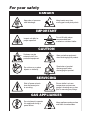
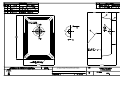
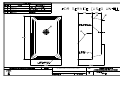
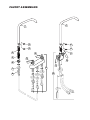
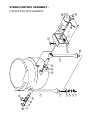
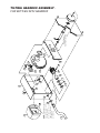
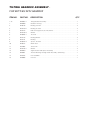
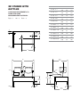
Operators Manual
Installation, Operation & Service
Direct Steam Table Top Kettles
Table-Top Direct
Steam Kettles
MODELS: KDT- 1 - T
KDT- 3 - T
KDT- 6 - T
KDT-12 - T
KDT-20 - T
SD Stands
MODELS: SD - 450
SD - 650
SD - 760
SD -1050
SD -1200
SD -1600
SD -1800
Kettles on
SD Stands
MODELS: SD -450 - K 6
SD -650 - K12
SD -760 - K12
SD -760 - K20
SD -1050 - K 6 6
SD -1200 - K 6 12
SD -1600 - K 6 20
SD -1600 - K12 12
SD -1600 - K12 20
SD -1600 - K20 20
KE50474 FOOT
™
Cleveland
Enodis
1333 East 179th St., Cleveland, Ohio, U.S.A. 44110
Phone: (216) 481-4900 Fax: (216) 481-3782
Visit our web site at www.clevelandrange.com
SE95008 Rev. 6
For your safety
DANGER
Keep clear of pressure
relief discharge.
Keep hands away from
moving parts and pinch points.
IMPORTANT
Do not fill kettle above
recommended level
marked on outside of kettle.
Inspect unit daily for
proper operation.
CAUTION
Surfaces may be
extremely hot! Use
protective equipment.
Wear protective equipment
when discharging hot product.
Do not lean on or place
objects on kettle lip.
Stand clear of product
discharge path when
discharging hot product.
SERVICING
Shut off power at main
fuse disconnect prior
to servicing.
0
Ensure kettle is at room
temperature and pressure
gauge is showing zero or less
prior to removing any fittings.
GAS APPLIANCES
Do not attempt to operate
this appliance during a
power failure.
Keep appliance and area free
and clear of combustibles.
INSTALLATION
GENERAL
Installation of the unit must be accomplished by
qualified installation personnel working to all
applicable local and national codes. Improper
installation of product could cause injury or damage.
This unit is built to comply with applicable
standards for manufacturers. Included among
those approval agencies are: UL, NSF,
ASME/Ntl.Bd., CSA, ETL, CE, and others. Many
local codes exist, and it is the responsibility of the
owner/installer to comply with these codes.
INSPECTION
Note: For SD Stands (with or without kettles) zero
clearance is required on the sides and back.
KETTLES
Table-top models must be positioned on a firm stand
or existing counter top and secured in place. An
optional modular cabinet base (SD Stand), with
level-adjustable legs is available .
1. Make two 1" holes for
the kettle legs.
A
DRILL TWO
1" HOLES
Before uncrating, visually inspect the unit for
evidence of damage during shipping. If damage
is noticed, do not unpack the unit, follow shipping
damage instructions.
SHIPPING DAMAGE
INSTRUCTIONS
If shipping damage to the unit is discovered or
suspected, observe the following guidelines in
preparing a shipping damage claim.
1. Write down a description of the damage or the
reason for suspecting damage as soon as it is
discovered. This will help in filling out the claim
forms later. If possible, take a polaroid picture.
2. As soon as damage is discovered or suspected,
notify the carrier that delivered the shipment.
3. Arrange for the carrier's representative to
examine the damage.
4. Fill out all carrier claims forms and have the
examining carrier sign and date each form.
KDT-1-T
KDT-3-T
KDT-6-T
KDT-12-T
KDT-20-T
8 1/8"
10"
12"
19 1/2"
23 3/4"
A
2. Remove the leg mounting
locknuts and washers from
the kettle's legs.
3. Install the legs into the two
1" holes.
4. Position washers as
illustrated and secure
the kettle to its' base by
refastening the locknut
from underneath the
cabinet or countertop.
C
N
OU
TE
RT
5. Once the kettle is secure,
screw the tilt handle into
the mounting block welded
to the side of the kettle.
6. Install service requirements
as required.
CLEARANCE REQUIREMENTS
The first installation step is to refer to the
SPECIFICATION DRAWINGS at the back of this manual
in order to determine the exact location of the kettle.
CLEARANCE REQUIREMENTS TO
COMBUSTIBLE AND NONCOMBUSTIBLE
SURFACES:
KDT-1-T
KDT-3-T & KDT-6-T
KDT-12-T & KDT-20-T
KETTLES c/w SD STAND
1. Place unit in desired location.
RIGHT
LEFT
BACK
4"
4"
4"
0"
4"
4"
0"
1"
1.75"
2. Place a carpenter's level on the kettle rim and
level the stand using the level adjustable feet.
3. Install service requirements as required.
OP
STEAM
CONDENSATE
All steam plumbing to and from the kettle and
steam boiler should be thoroughly cleaned and
inspected for dirt and debris before final
connection to the kettle are made.
The stand comes factory plumbed so the condensate
is connected to the stands drain manifold.
Generally, kettles require 1/2" i.p.s. pipe, 10-45 psi
steam pressure. If the steam supply pressure
exceeds 45 psi, a pressure reducing valve is
required. The steam inlet is at the right side of the
kettle, as n from the front.
The water faucet (optional on kettles purchased
without SD stands) with swing spout, requires 1/2
inch O.D. copper tube plumbing for hot or cold water
supplies to the faucet (SPK - cold water connection
only, DPK - hot and cold water connection).
A pressure reducing valve is required on the
incoming line as shown below. The relief valve
should have a capacity of 300 lb/hr (136 kg/hr).
FINAL INSTALLATION CHECK
CONDENSATE
2. Slowly turn the steam supply valve's knob to
the open position.
(Kettles c/w SD Stands)
POTABLE WATER
1. Partially fill the kettle with water.
(Kettles without SD Stands)
Maximum pressure rating on table-top kettles is
50psi. It is highly recommended that a pressure relief
valve equal to or less than this pressure be installed
on the incoming steam line close to the kettle.
3. Release the safety valve, ensuring that the
steam escapes freely. Stay clear of steam
exhaust when releasing the safety valve.
4. Observe that the water in the kettle comes to a boil.
A steam condensate trap must be plumbed to a drain,
using minimum 1/2" NPT plumbing. The condensate line
is limited to a maximum rise of 10 feet in order for the
steam pressure to adequately force the condensate
through the plumbing. Any higher rise requires a pump.
5. Close the steam supply valve.
6. Drain off the water by tilting the kettle.
If the steam boiler to which this kettle is installed has a
condensate return (closed loop system), a 1/2" steam
strainer, a 1/2" steam trap, and a 1/2" check valve must
be installed on the output (condensate) side of the kettle.
RECOMMENDED PIPING
SCHEMATICS
KETTLES
(all service connections shown supplied by others)
MANUAL
STEAM
VALVE
CONDENSATE RETURN
TO DRAIN OR BOILER
CONDENSATE LINE
UNION
KETTLES c/w
SD STANDS
STRAINER
CHECK
VALVE
STEAM
TRAP STRAINER
UNION
RELIEF
VALVE
RELIEF
VALVE
PRESSURE
REDUCING
VALVE
STRAINER
SHUT OFF
VALVE
STEAM
IN
UNION
TO DRAIN (CONDENSATE RETURN PLUMBED TO 1 1/2" DRAIN MANIFOLD)
PRESSURE
REDUCING
VALVE
STEAM
IN
SHUT OFF
VALVE
OPERATING INSTRUCTIONS
CLEVELAND STEAM COOKING EQUIPMENT IS INTENDED FOR
COMMERCIAL USE ONLY BY PROFESSIONALLY TRAINED PERSONNEL.
OPERATION
1. Ensure that there is an adequate steam
supply to the kettle.
2. Turn the steam control valve to
the open position by turning the
knob counter-clockwise, then allow
the kettle to preheat.
NOTE: When cooking egg and milk products, the
kettle should NOT be preheated, as products of
this nature adhere to hot cooking surfaces. These
types of foods should be placed in the kettle
before heating is begun.
FOR KETTLE/STEAMER COMBINATIONS:
If the boiler in a steamer is supplying steam to a
kettle, always heat the kettle first. After the kettle
contents are heated, and the boiler's steam
pressure returns to normal, the steamer may be
used. Pressure steamer compartments should be
sequentially started, and preheated before
cooking.
NOTE: As with cleaning food soil from any
cookware, art important part of kettle cleaning is
to prevent food from drying on. For this reason,
cleaning should be completed immediately after
cooked foods are removed. . Please read the
"Care and Cleaning" instructions for detailed kettle
washing procedures
3. Fill kettle with product to desired level.
4. When the product has reached
the desired temperature, regulate
the heat, as required, by turning
the steam control valve clockwise
for less steam, and therefore, a
lower temperature.
5. When cooking is complete,
close the steam control valve by
turning the knob clockwise.
Marine Lock
(12 & 20 gal. models only)
If your unit is equipped with
a marine lock to prevent
accidental tilting, it must be
inspected daily to insure it
moves freely and
automatically locks into place when kettle is
returned to upright position.
MARINE
LOCK
Use the following procedure to tilt the kettle.
1. Securely grasp the tilt handle.
2. Push the marine lock button down to unlock
tilting mechanism.
3. Pull the handle to tilt the kettle.
4. When you return the kettle to its' original upright
position the marine lock will latch automatically.
CLEANING INSTRUCTIONS
CAUTION
SURFACES MAY
BE EXTREMELY HOT!
CARE AND CLEANING
Cooking equipment must be cleaned regularly to
maintain its fast, efficient cooking performance and
to ensure its continued safe, reliable operation. The
best time to clean is shortly after each use (allow
unit to cool to a safe temperature).
CLEANING INSTRUCTIONS
1. Turn unit off.
2. Remove drain screen (if applicable). Thoroughly
wash and rinse the screen either in a sink or a
dishwasher.
3. Prepare a warm water and mild detergent solution in
the unit.
4. Remove food soil using a nylon brush.
5. Loosen food which is stuck by allowing it to soak at
a low temperature setting.
6. Drain unit.
WARNINGS
➩
7. Rinse interior thoroughly.
Do not use detergents or
cleansers that are chloride
based or contain quaternary
salt.
Chloride Cleaners
➩
Do not use a metal bristle
brush or scraper.
8. If the unit is equipped with a Tangent Draw-Off
Valve, clean as follows:
a) Disassemble the draw-off valve first by turning
the valve knob counter-clockwise, then turning
the large hex nut counter-clockwise until the
valve stem is free of the valve body.
b) In a sink, wash and rinse the inside of the valve
body using a nylon brush.
c) Use a nylon brush to clean tangent draw-off tube.
d) Rinse with fresh water.
e) Reassemble the draw-off valve by reversing the
procedure for disassembly. The valve's hex nut
should be hand tight only.
Wire Brush &
➩
Steel wool should never be
used for cleaning the stainless
steel.
9. If the unit is equipped with a Butterfly Valve, clean
as follows:
a) Place valve in open position.
b) Wash using a warm water and mild detergent
solution.
Steel Pads
c) Remove food deposits using a nylon brush.
➩
Unit should never be cleaned
with a high pressure spray
hose.
d) Rinse with fresh water.
e) Leave valve open when unit is not in use.
10. Using mild soapy water and a damp sponge, wash
the exterior, rinse, and dry.
NOTES
High Pressure
Spray Hose
➩
Do not leave water sitting in unit
when not in use.
➩ For more difficult cleaning applications one of the
following can be used: alcohol, baking soda, vinegar,
or a solution of ammonia in water.
➩ Leave the cover off when the kettle is not in use.
Stagnant
Water
➩ For more detailed instructions refer to the Nafem
Stainless Steel Equipment Care and Cleaning manual
(supplied with unit).
STAINLESS STEEL EQUIPMENT CARE AND CLEANING
(Suppied courtesy of Nafem. For more information visit their web site at www.nafem.org)
Contrary to popular belief, stainless steels ARE susceptible to rusting.
4. Treat your water.
Though this is not always practical, softening hard water can do much
to reduce deposits. There are certain filters that can be installed to
remove distasteful and corrosive elements. To insure proper water
treatment, call a treatment specialist.
Corrosion on metals is everywhere. It is recognized quickly on iron and
steel as unsightly yellow/orange rust. Such metals are called “active”
because they actively corrode in a natural environment when their atoms
combine with oxygen to form rust.
Stainless steels are passive metals because they contain other metals, like
chromium, nickel and manganese that stabilize the atoms. 400 series
stainless steels are called ferritic, contain chromium, and are magnetic;
300 series stainless steels are called austenitic, contain chromium and
nickel; and 200 series stainless, also austenitic, contains manganese,
nitrogen and carbon. Austenitic types of stainless are not magnetic, and
generally provide greater resistance to corrosion than ferritic types.
With 12-30 percent chromium, an invisible passive film covers the steel’s
surface acting as a shield against corrosion. As long as the film is intact
and not broken or contaminated, the metal is passive and stain-less. If the
passive film of stainless steel has been broken, equipment starts to
corrode. At its end, it rusts.
5. Keep your food equipment clean.
Use alkaline, alkaline chlorinated or non-chloride cleaners at
recommended strength. Clean frequently to avoid build-up of hard,
stubborn stains. If you boil water in stainless steel equipment,
remember the single most likely cause of damage is chlorides in the
water. Heating cleaners that contain chlorides have a similar effect.
6. Rinse, rinse, rinse.
If chlorinated cleaners are used, rinse and wipe equipment and
supplies dry immediately. The sooner you wipe off standing water,
especially when it contains cleaning agents, the better. After wiping
equipment down, allow it to air dry; oxygen helps maintain the
stainless steel’s passivity film.
Enemies of Stainless Steel
There are three basic things which can break down stainless steel’s
passivity layer and allow corrosion to occur.
7. Never use hydrochloric acid (muriatic acid) on stainless steel.
8. Regularly restore/passivate stainless steel.
1. Mechanical abrasion
2. Deposits and water
Recommended cleaners for specific situations
3. Chlorides
Job
Cleaning Agent
Comments
Mechanical abrasion means those things that will scratch a steel surface.
Steel pads, wire brushes and scrapers are prime examples.
Routine cleaning
Soap, ammonia,
detergent, Medallion
Apply with cloth or sponge
Fingerprints & smears
Arcal 20, Lac-O-Nu
Ecoshine
Provides barrier film
Stubborn stains &
discoloration
Cameo, Talc, Zud,
First Impression
Rub in direction of polish lines
Grease & fatty acids,
blood, burnt-on-foods
Easy-off, De-Grease
It Oven Aid
Excellent removal on all finishes
Grease & oil
Any good
commercial detergent
Apply with sponge or cloth
Restoration/Passivation
Benefit, Super Sheen
Water comes out of the faucet in varying degrees of hardness. Depending
on what part of the country you live in, you may have hard or soft water.
Hard water may leave spots, and when heated leave deposits behind that
if left to sit, will break down the passive layer and rust stainless steel. Other
deposits from food preparation and service must be properly removed.
Chlorides are found nearly everywhere. They are in water, food and table
salt. One of the worst chloride perpetrators can come from household and
industrial cleaners.
So what does all this mean? Don’t Despair!
Here are a few steps that can help prevent stainless steel rust.
1. Use the proper tools.
When cleaning stainless steel products, use non-abrasive tools. Soft
cloths and plastic scouring pads will not harm steel’s passive layer.
Stainless steel pads also can be used but the scrubbing motion must
be in the direction of the manufacturers’ polishing marks.
2. Clean with the polish lines.
Some stainless steel comes with visible polishing lines or “grain.”
When visible lines are present, always scrub in a motion parallel to the
lines. When the grain cannot be seen, play it safe and use a soft cloth
or plastic scouring pad.
Review
1. Stainless steels rust when passivity (film-shield) breaks down as a
result of scrapes, scratches, deposits and chlorides.
2. Stainless steel rust starts with pits and cracks.
3. Use the proper tools. Do not use steel pads, wire brushes or scrapers
to clean stainless steel.
4. Use non-chlorinated cleaners at recommended concentrations. Use
only chloride- free cleaners.
5. Soften your water. Use filters and softeners whenever possible.
6. Wipe off cleaning agent(s) and standing water as soon as possible.
Prolonged contact causes eventual problems.
3. Use alkaline, alkaline chlorinated or non-chloride containing cleaners.
While many traditional cleaners are loaded with chlorides, the industry
is providing an ever-increasing choice of non-chloride cleaners. If you
are not sure of chloride content in the cleaner used, contact your cleaner
supplier. If your present cleaner contains chlorides, ask your supplier if
they have an alternative. Avoid cleaners containing quaternary salts; it
also can attack stainless steel and cause pitting and rusting.
To learn more about chloride-stress corrosion and how to prevent it,
contact the equipment manufacturer or cleaning materials supplier.
Developed by Packer Engineering, Naperville, Ill., an independent testing
laboratory.
SERVICE PARTS
STEAM CONTROL ASSEMBLY
14
26
5
5
15
4
3
22
16
1
2
5
3
4
23
24
25
4
6
11
7
8
9
28
23
10
1
21
12
13
7
20
19
18
17
29
8
21
20
9
5
23
27
5
4
19
7
4
18
9
6
7
8
17
6
23
8
9
12
13
STEAM CONTROL ASSEMBLY
ITEM NO.
PART NO.
DESCRIPTION
QTY.
1.
FA11056
Binding Head Screw, 6-32 x 1/2" lg. . . . . . . . . . . . . . . . . . . . . . . . . . . . . . . . . . .4
2.
KE50458
End Cap, condensate return . . . . . . . . . . . . . . . . . . . . . . . . . . . . . . . . . . . . . . . .1
3.
KE50455-1
Trunnion, condensate return . . . . . . . . . . . . . . . . . . . . . . . . . . . . . . . . . . . . . . . .1
4.
FA05002-35
"O" Ring . . . . . . . . . . . . . . . . . . . . . . . . . . . . . . . . . . . . . . . . . . . . . . . . . . . . . . . .2
5.
FA05002-37
"O" Ring . . . . . . . . . . . . . . . . . . . . . . . . . . . . . . . . . . . . . . . . . . . . . . . . . . . . . . . .4
6.
KE50460-1
Trunnion, steam inlet . . . . . . . . . . . . . . . . . . . . . . . . . . . . . . . . . . . . . . . . . . . . . .1
7.
FA11089
Binding Head Screw, 8-32 x 1/4" lg. . . . . . . . . . . . . . . . . . . . . . . . . . . . . . . . . . .1
8.
KE51713
Washer, steam valve . . . . . . . . . . . . . . . . . . . . . . . . . . . . . . . . . . . . . . . . . . . . . .1
9.
KE50459
Operating Stem . . . . . . . . . . . . . . . . . . . . . . . . . . . . . . . . . . . . . . . . . . . . . . . . . .1
10.
KE50457
End Cap, steam inlet . . . . . . . . . . . . . . . . . . . . . . . . . . . . . . . . . . . . . . . . . . . . . .1
11.
SE00028
Steam Control Knob Assembly (c/w Item No. 12, 13 & Knob) . . . . . . . . . . . . . .1
12.
KE51888
Retaining Washer . . . . . . . . . . . . . . . . . . . . . . . . . . . . . . . . . . . . . . . . . . . . . . . .1
13.
FA11092
Binding Head Screw, 8-32 x 1/2" lg. . . . . . . . . . . . . . . . . . . . . . . . . . . . . . . . . . .1
14.
KE50151-E
Knob, threaded (after 07/94) . . . . . . . . . . . . . . . . . . . . . . . . . . . . . . . . . . . . . . .1
KE50151
Knob, non threaded (prior to 06/94) . . . . . . . . . . . . . . . . . . . . . . . . . . . . . . . . . .1
KE50886-1
KE50886-3
Handle, KDT-1-T . . . . . . . . . . . . . . . . . . . . . . . . . . . . . . . . . . . . . . . . . . . . . . . . .1
Handle, KDT-3-T . . . . . . . . . . . . . . . . . . . . . Requires
. . . . . . . .Knob
. . . . .- . . . . . . . . . . . . . . .1
Item No.
Handle, KDT-6-T & KDT-12-T . . . . . . . . . . . . . KE50151-E
. . . . . . . . . . . . . . . . . . . . . . . . . .1
KE50886-4
Handle, KDT-20-T . . . . . . . . . . . . . . . . . . . . . . . . . . . . . . . . . . . . . . . . . . . . . . . .1
16.
KE50475
Plug Button . . . . . . . . . . . . . . . . . . . . . . . . . . . . . . . . . . . . . . . . . . . . . . . . . . . . .1
17.
KE52697
Lock Nut, 1/2" NPS . . . . . . . . . . . . . . . . . . . . . . . . . . . . . . . . . . . . . . . . . . . . . . .2
18.
FA32500
Lockwasher . . . . . . . . . . . . . . . . . . . . . . . . . . . . . . . . . . . . . . . . . . . . . . . . . . . . .2
19.
FA30502
Washer, satin coat . . . . . . . . . . . . . . . . . . . . . . . . . . . . . . . . . . . . . . . . . . . . . . . .2
20.
KE50467
Washer, Foot . . . . . . . . . . . . . . . . . . . . . . . . . . . . . . . . . . . . . . . . . . . . . . . . . . . .2
15.
KE50886-2
21.
KE50465
Service Pipe, KDT-1-T & KDT-3-T . . . . . . . . . . . . . . . . . . . . . . . . . . . . . . . . . . . .2
KE52030
Service Pipe, KDT-6-T . . . . . . . . . . . . . . . . . . . . . . . . . . . . . . . . . . . . . . . . . . . . .2
KE50463
Service Pipe, KDT-12-T . . . . . . . . . . . . . . . . . . . . . . . . . . . . . . . . . . . . . . . . . . . .2
KE50464
Service Pipe, KDT-20-T . . . . . . . . . . . . . . . . . . . . . . . . . . . . . . . . . . . . . . . . . . . .2
T40272
Leg Assembly, KDT-1-T (c/w Item No. 17-21) . . . . . . . . . . . . . . . . . . . . . . . . . .2
T40218
Leg Assembly, KDT-3-T (c/w Item No. 17-21) . . . . . . . . . . . . . . . . . . . . . . . . . .2
KE00896
Leg Assembly, KDT-6-T (c/w Item No. 17-21) . . . . . . . . . . . . . . . . . . . . . . . . . .2
KE00203
Leg Assembly, KDT-12-T (c/w Item No. 17-21) . . . . . . . . . . . . . . . . . . . . . . . . .2
KE00204
Leg Assembly, KDT-20-T (c/w Item No. 17-21) . . . . . . . . . . . . . . . . . . . . . . . . .2
23.
FA05002-12
"O" Ring . . . . . . . . . . . . . . . . . . . . . . . . . . . . . . . . . . . . . . . . . . . . . . . . . . . . . . . .1
24.
KE01115-1
Right Hand Marine Lock Latch, KDT-12-T & KDT20-T only . . . . . . . . . . . . . . . .1
24.
KE01115
Left Hand Marine Lock Latch, KDT-12-T & KDT20-T only . . . . . . . . . . . . . . . . .1
25.
KE52632
Crown Nut, KDT-12-T & KDT20-T only . . . . . . . . . . . . . . . . . . . . . . . . . . . . . . . .1
26.
SE00096
Steam Outlet Assembly . . . . . . . . . . . . . . . . . . . . . . . . . . . . . . . . . . . . . . . . . . . .1
27.
SE00011
Trunnion Assembly, steam inlet . . . . . . . . . . . . . . . . . . . . . . . . . . . . . . . . . . . . . .1
28.
SE00029
Operating Stem Assembly, steam inlet . . . . . . . . . . . . . . . . . . . . . . . . . . . . . . . .1
29.
SE00030
Steam Inlet Control Assembly . . . . . . . . . . . . . . . . . . . . . . . . . . . . . . . . . . . . . . .1
22.
SE00112
Trunnion rebuild kit
00908
O Ring Lubrication
PLUMBING ASSEMBLY
(for SD Stands)
29
See Steam
Control Drawing
See Steam
Control Drawing
1
2
5
STEAM
IN
3
22
20
19
4
7
21
6
CONDENSATE
RETURN
11
10
9
See Steam
Control Drawing
8
23
18
17
30
12
13
16
2
1
15
28
14
27
26
1
25
Steam In Configuration for
SD Stand with Two Kettles
24
2
1
STEAM
IN
PLUMBING ASSEMBLY (for SD Stands)
ITEM NO.
PART NO.
DESCRIPTION
1.
FI00169
Tee, 1/2" NPT.
QTY.
(single kettle units) . . . . . . . . . . . . .1
(twin kettle units) . . . . . . . . . . . . . . .3
2.
KE54941-5
Safety Valve, 50 PSI, 1/2" (North America) (single kettle units) . . . . . . . . . . . . .1
(twin kettle units) . . . . . . . . . . . . . . .2
KE54941-31
Safety Valve, 50 PSI, 1/2", (Europe)
(single kettle units) . . . . . . . . . . . . .1
(twin kettle units) . . . . . . . . . . . . . . .2
3.
FA95010
Jam Nut, #3/4-10 . . . . . . . . . . . . . . . . . . . . . . . . . . . . . . . . . . . . . . . . . . . . . . . . .4
4.
KE51340
Leg . . . . . . . . . . . . . . . . . . . . . . . . . . . . . . . . . . . . . . . . . . . . . . . . . . . . . . . . . . .4
5.
SD50000
Strainer Assembly . . . . . . . . . . . . . . . . . . . . . . . . . . . . . . . . . . . . . . . . . . . . . . . .1
6.
SD50042
Radiator Hose, 4" lg. . . . . . . . . . . . . . . . . . . . . . . . . . . . . . . . . . . . . . . . . . . . . . .1
7.
FI05131
Hose Clamp . . . . . . . . . . . . . . . . . . . . . . . . . . . . . . . . . . . . . . . . . . . . . . . . . . . .2
8.
SD50043
Nipple, threaded one end only . . . . . . . . . . . . . . . . . . . . . . . . . . . . . . . . . . . . . .1
9.
KE51367
Check Valve, 1 1/4" NPT . . . . . . . . . . . . . . . . . . . . . . . . . . . . . . . . . . . . . . . . . . .1
10.
FI00670
Nipple . . . . . . . . . . . . . . . . . . . . . . . . . . . . . . . . . . . . . . . . . . . . . . . . . . . . . . . . .1
11.
FI00136
90° Street Elbow, 1 1/4" NPT . . . . . . . . . . . . . . . . . . . . . . . . . . . . . . . . . . . . . . . .1
12.
FI00191
Cap, 1 1/2" NPT . . . . . . . . . . . . . . . . . . . . . . . . . . . . . . . . . . . . . . . . . . . . . . . . . .1
13.
KE00648
Drain Pipe Assembly . . . . . . . . . . . . . . . . . . . . . . . . . . . . . . . . . . . . . . . . . . . . . .1
14.
FI00044
90° Elbow, 1 1/2" NPT . . . . . . . . . . . . . . . . . . . . . . . . . . . . . . . . . . . . . . . . . . . . .1
15.
FI05027
Pipe Strap . . . . . . . . . . . . . . . . . . . . . . . . . . . . . . . . . . . . . . . . . . . . . . . . . . . . . .2
16.
FI05047
Reducer . . . . . . . . . . . . . . . . . . . . . . . . . . . . . . . . . . . . . . . . . . . . . . . . . . . . . . . .1
17.
FI05077
Compression Elbow
18.
SD50027
Steam Trap . . . . . . . . . . . . . . . . . . . . . . . . . . . . . . . . . . . . . . . . . . . . . . . . . . . . .1
19.
FI05049
Male Connector . . . . . . . . . . . . . . . . . . . . . . . . . . . . . . . . . . . . . . . . . . . . . . . . . .1
20.
KE51249
Strainer, 1/2" NPT . . . . . . . . . . . . . . . . . . . . . . . . . . . . . . . . . . . . . . . . . . . . . . . .1
21.
FI00596
Nipple, 1/2" NPT . . . . . . . . . . . . . . . . . . . . . . . . . . . . . . . . . . . . . . . . . . . . . . . . .1
22.
FI00266
Coupling, 1/2" NPT . . . . . . . . . . . . . . . . . . . . . . . . . . . . . . . . . . . . . . . . . . . . . . .1
23.
FI05048
Compression Tee
24.
FI00586
Nipple . . . . . . . . . . . . . . . . . . . . . . . . . . . . . . . . . . . . . . . . . . . . . . . . . . . . . . . . .1
25.
FI05029
Hose Fitting, 1/2" . . . . . . . . . . . . . . . . . . . . . . . . . . . . . . . . . . . . . . . . . . . . . . . . .2
26.
KE51391
Hose Clamp . . . . . . . . . . . . . . . . . . . . . . . . . . . . . . . . . . . . . . . . . . . . . . . . . . . .2
27.
SD50034
Hose, 20"
(SD1050K66) . . . . . . . . . . . . . . . . . .1
SD50035
Hose, 17"
(SD1200K612) . . . . . . . . . . . . . . . . .1
SD50036
Hose, 27"
(SD1600K620, 1212, 12,20 & 2020) .1
28.
FI05028
90° Swivel Elbow . . . . . . . . . . . . . . . . . . . . . . . . . . . . . . . . . . . . . . . . . . . . . . . . .1
29.
SDP
Sliding Drain Pan Assembly . . . . . . . . . . . . . . . . . . . . . . . . . . . . . . . . . . . . . . . .1
30.
(single kettle units) . . . . . . . . . . . . .1
(twin kettle units) . . . . . . . . . . . . . . .1
Front Access Panels
SD50067
(SD450 series) . . . . . . . . . . . . . . . . . . . . . . . . . . . . . . . . . . . . . . . . . . . . . . . . . . .1
SD50068
(SD650 series) . . . . . . . . . . . . . . . . . . . . . . . . . . . . . . . . . . . . . . . . . . . . . . . . . . .1
SD50106
(SD760 series) . . . . . . . . . . . . . . . . . . . . . . . . . . . . . . . . . . . . . . . . . . . . . . . . . . .1
SD50069
(SD1050 series) . . . . . . . . . . . . . . . . . . . . . . . . . . . . . . . . . . . . . . . . . . . . . . . . . .1
SD50070
(SD1200 series) . . . . . . . . . . . . . . . . . . . . . . . . . . . . . . . . . . . . . . . . . . . . . . . . . .1
SD50071
(SD1600 series) . . . . . . . . . . . . . . . . . . . . . . . . . . . . . . . . . . . . . . . . . . . . . . . . . .1
CLEVELAND RANGE LTD.
8251 KEELE STREET, CONCORD, ONTARIO, CANADA
CLEVELAND RANGE LTD.
8251 KEELE STREET, CONCORD, ONTARIO, CANADA
FAUCET ASSEMBLIES
1
1
4
5
2
2
3
3
12
4
11
12
6
11
7
8
9
10
7
8
9
10
1
2
3
4
5
6
11
10
11
12
6
5
14
See Tilting
Gearbox Assembly
13
16
21
15
17
20
19
18
22
STEAM CONTROL ASSEMBLY FOR KETTLES WITH GEARBOX
FAUCET ASSEMBLIES
ITEM NO.
PART NO.
DESCRIPTION
QTY.
1.
KE50825-8
6 gallon . . . . . . . . . . . . . . . . . . . . . . . . . . . . . . . . . . . . . . . . .1
KE50825-1
12 gallon . . . . . . . . . . . . . . . . . . . . . . . . . . . . . . . . . . . . . . . .1
KE50825-1
20 gallon . . . . . . . . . . . . . . . . . . . . . . . . . . . . . . . . . . . . . . . .1
2.
FA95022
Retaining Ring . . . . . . . . . . . . . . . . . . . . . . . . . . . . . . . . . . . . . . . . . . . . . . . . . . . .1
3.
FA05002-19
"O" Ring . . . . . . . . . . . . . . . . . . . . . . . . . . . . . . . . . . . . . . . . . . . . . . . . . . . . . . . . .1
4.
KE51736
Long Faucet Nut . . . . . . . . . . . . . . . . . . . . . . . . . . . . . . . . . . . . . . . . . . . . . . . . . .1
5.
SD50097
Flanged Nut, 3/4" NPT, Chrome Plated . . . . . . . . . . . . . . . . . . . . . . . . . . . . . . . . .1
6.
KE51585
Faucet Spout Fitting . . . . . . . . . . . . . . . . . . . . . . . . . . . . . . . . . . . . . . . . . . . . . . . .1
7.
SD50098
Locknut, 3/4" NPT . . . . . . . . . . . . . . . . . . . . . . . . . . . . . . . . . . . . . . . . . . . . . . . . . .1
8.
FI00266
Coupling, 1/2" NPT . . . . . . . . . . . . . . . . . . . . . . . . . . . . . . . . . . . . . . . . . . . . . . . . .1
9.
KE51899
Double Pantry Control Valve . . . . . . . . . . . . . . . . . . . . . . . . . . . . . . . . . . . . . . . . .1
(c/w Item No. 11&12)
10.
KE51403
Double Pantry Control Valve . . . . . . . . . . . . . . . . . . . . . . . . . . . . . . . . . . . . . . . . .1
(c/w Item No. 11&12)
KE51401
Single Pantry Control Valve . . . . . . . . . . . . . . . . . . . . . . . . . . . . . . . . . . . . . . . . . .1
(c/w Item No. 12)
11.
SE50020
Hot Water Stem Assembly . . . . . . . . . . . . . . . . . . . . . . . . . . . . . . . . . . . . . . . . . . .1
12.
SE50021
Cold Water Stem Assembly . . . . . . . . . . . . . . . . . . . . . . . . . . . . . . . . . . . . . . . . . .1
STEAM CONTROL ASSEMBLY FOR KETTLES WITH GEARBOX
ITEM NO.
PART NO.
DESCRIPTION
QTY.
1.
KE52697
Lock Nut, 1/2" NPS . . . . . . . . . . . . . . . . . . . . . . . . . . . . . . . . . . . . . . . . . . . . . . .2
2.
FA32500
Lockwasher . . . . . . . . . . . . . . . . . . . . . . . . . . . . . . . . . . . . . . . . . . . . . . . . . . . . .2
3.
FA30502
Washer, satin coat . . . . . . . . . . . . . . . . . . . . . . . . . . . . . . . . . . . . . . . . . . . . . . . .2
4.
KE50467
Washer, Foot . . . . . . . . . . . . . . . . . . . . . . . . . . . . . . . . . . . . . . . . . . . . . . . . . . . .2
5.
KE50463
Service Pipe . . . . . . . . . . . . . . . . . . . . . . . . . . . . . . . . . . . . . . . . . . . . . . . . . . . .2
6.
KE00203
Leg Assembly . . . . . . . . . . . . . . . . . . . . . . . . . . . . . . . . . . . . . . . . . . . . . . . . . . .2
7.
FA11056
Binding Head Screw, 6-32 x 1/2" lg. . . . . . . . . . . . . . . . . . . . . . . . . . . . . . . . . . .2
8.
KE50458
End Cap, condensate return . . . . . . . . . . . . . . . . . . . . . . . . . . . . . . . . . . . . . . . .1
9.
KE50455-1
Trunnion, condensate return . . . . . . . . . . . . . . . . . . . . . . . . . . . . . . . . . . . . . . . .1
10.
FA05002-35
"O" Ring . . . . . . . . . . . . . . . . . . . . . . . . . . . . . . . . . . . . . . . . . . . . . . . . . . . . . . . .1
11.
FA05002-37
"O" Ring . . . . . . . . . . . . . . . . . . . . . . . . . . . . . . . . . . . . . . . . . . . . . . . . . . . . . . . .4
12.
KE54752
Trunnion . . . . . . . . . . . . . . . . . . . . . . . . . . . . . . . . . . . . . . . . . . . . . . . . . . . . . . . .1
13.
FA11509-1
Bolt, 1/2-13 x 3/4" lg . . . . . . . . . . . . . . . . . . . . . . . . . . . . . . . . . . . . . . . . . . . . . .1
14.
FA11089
Binding Head Screw, 8-32 x 1/4" lg. . . . . . . . . . . . . . . . . . . . . . . . . . . . . . . . . . .1
15.
KE51713
Washer, steam valve . . . . . . . . . . . . . . . . . . . . . . . . . . . . . . . . . . . . . . . . . . . . . .1
16.
FA05002-12
"O" Ring . . . . . . . . . . . . . . . . . . . . . . . . . . . . . . . . . . . . . . . . . . . . . . . . . . . . . . . .1
17.
KE54753
Operating Stem . . . . . . . . . . . . . . . . . . . . . . . . . . . . . . . . . . . . . . . . . . . . . . . . . .1
18.
KE51888
Retaining Washer . . . . . . . . . . . . . . . . . . . . . . . . . . . . . . . . . . . . . . . . . . . . . . . .1
19.
SE00028
Steam Control Knob (includes Item #18 & 20) . . . . . . . . . . . . . . . . . . . . . . . . . .1
20.
FA11092
Binding Head Screw, 8-32 x 1/2" lg. . . . . . . . . . . . . . . . . . . . . . . . . . . . . . . . . . .1
21.
KE54729
Gear Box Cover . . . . . . . . . . . . . . . . . . . . . . . . . . . . . . . . . . . . . . . . . . . . . . . . .1
22.
FA11146
Binding Head Screw, 8-32 x 3/8" . . . . . . . . . . . . . . . . . . . . . . . . . . . . . . . . . . . .4
14
6
Do not damage the outside
edges of the gearbox
housing when
tack welding.
5
NOTE: Item #14 to be tack welded
flush outside in the gearbox
housing (item #1).
1
3
2
1
7
4
8
3
7
9
10
13
12
15
11
14
16
12
See Steam
Control Assembly
2
TILTING GEARBOX ASSEMBLY FOR KETTLES WITH GEARBOX
TILTING GEARBOX ASSEMBLY FOR KETTLES WITH GEARBOX
ITEM NO.
PART NO.
DESCRIPTION
QTY.
1.-16.
KE02062-1
Tilting Gearbox Assembly . . . . . . . . . . . . . . . . . . . . . . . . . . . . . . . . . . . . . . . . . .1
1.
KE02060
Gearbox Housing . . . . . . . . . . . . . . . . . . . . . . . . . . . . . . . . . . . . . . . . . . . . . . . .1
2.
KE50198
Bearing, trunnion . . . . . . . . . . . . . . . . . . . . . . . . . . . . . . . . . . . . . . . . . . . . . . . . .2
3.
KE54739-2
Bearing, tilt shaft . . . . . . . . . . . . . . . . . . . . . . . . . . . . . . . . . . . . . . . . . . . . . . . . .2
4.
KE54737
End Housing Spacer, tilt shaft, bronze . . . . . . . . . . . . . . . . . . . . . . . . . . . . . . . .1
5.
KE54738-3
Washer . . . . . . . . . . . . . . . . . . . . . . . . . . . . . . . . . . . . . . . . . . . . . . . . . . . . . . . .1
6.
KE50306-1
Tilt Shaft . . . . . . . . . . . . . . . . . . . . . . . . . . . . . . . . . . . . . . . . . . . . . . . . . . . . . . . .1
7.
KE52192
Bearing Washer . . . . . . . . . . . . . . . . . . . . . . . . . . . . . . . . . . . . . . . . . . . . . . . . . .2
8.
KE52191
Bearing . . . . . . . . . . . . . . . . . . . . . . . . . . . . . . . . . . . . . . . . . . . . . . . . . . . . . . . .1
9.
KE50426-3
Spacer, Tilt Shaft . . . . . . . . . . . . . . . . . . . . . . . . . . . . . . . . . . . . . . . . . . . . . . . . .1
10.
KE50315
Worm Gear . . . . . . . . . . . . . . . . . . . . . . . . . . . . . . . . . . . . . . . . . . . . . . . . . . . . .1
11.
FA95005
Tension Pin . . . . . . . . . . . . . . . . . . . . . . . . . . . . . . . . . . . . . . . . . . . . . . . . . . . . .1
12.
KE54738-1
Washer . . . . . . . . . . . . . . . . . . . . . . . . . . . . . . . . . . . . . . . . . . . . . . . . . . . . . . . .2
13.
KE02059
Segment Gear and Spacer Assembly . . . . . . . . . . . . . . . . . . . . . . . . . . . . . . . .1
14.
KE02061
Trunnion Bearing Housing Holder Assembly c/w Bearing . . . . . . . . . . . . . . . . .1
15.
FA10485
Hex Head Bolt . . . . . . . . . . . . . . . . . . . . . . . . . . . . . . . . . . . . . . . . . . . . . . . . . . .1
16.
FA20008
Hex Nut . . . . . . . . . . . . . . . . . . . . . . . . . . . . . . . . . . . . . . . . . . . . . . . . . . . . . . . .1
MAINTENANCE
ALL SERVICE MUST BE PERFORMED BY A
QUALIFIED SERVICE TECHNICIAN.
This kettle requires very little preventative maintenance other than daily cleaning.
The pressure relief valve must be tested twice a year.
PRESSURE RELIEF VALVE
TESTING PROCEDURE
WARNING
Kettle will be hot. Use gloves for protection.
MARINE LOCK
Inspect lock at least twice yearly.
1. Check for excessive play or wear on pivot.
Adjust or replace as required.
2.
The pressure relief valve (optional on kettles) must
be checked at least twice a year as part of the
normal maintenance performed.
1. Open steam valve and preheat kettle.
Insure lock is catching over the centre of the
stop pin and not bent to one side or the other.
Adjust or replace as required.
WARRANTY
2. Stand to the side of the pressure relief valve
discharge tube and pull ring three or four
times to insure free movement. Hold valve
open for two seconds each time, insuring
there is rapid steam escape each time.
Our Company supports a worldwide network of
Maintenance and Repair Centers. Contact your
nearest Maintenance and Repair Centre for
replacement parts, service, or information
regarding the proper maintenance and repair of
your cooking equipment
3. If valve appears to be sticking replace
pressure relief valve. If foreign material is
discharged, replace pressure relief valve and
eliminate the source of contamination.
In order to preserve the various agency safety
certification (UL, NSF, ASME/Ntl. Bd., etc.), only
factory-supplied replacement parts should be
used. The use of other than factory supplied
replacement parts will void warranty.
STEAM TRAP
To remove line condensate that forms inside the
steam jacket, each kettle should be equipped with
a steam trap in the line of the kettle outlet to the
drain. A good steam trap at startup releases air
and wet steam into the drain line for a few
minutes, then holds the steam jacket. During
cooking, the trap periodically releases
accumulated condensate. If the kettle's cooking
performance becomes inadequate after long use,
replacement of the steam trap with a new one may
restore kettle operation to peak efficiency.
TROUBLESHOOTING GUIDE
This section contains information intended for use by Authorized Service Personnel only.
PROBLEM
A/ Kettle heats too slowly or does not come to a boil.
Probable Cause
Remedy
1. Inadequate steam flow.
Check for correct steam using chart below.
If kettle is connected to a steamer and powered by a
generator the units should be operated sequentially
(kettle boiling first, then start steamer).
2. Steam trap not operating properly.
The trap should open periodically to
dump condensate, then close.
If it does not open or close it should be
cleaned or replaced.
3. Food batches are not always the same.
When checking make certain that the original state (ie.
fresh or frozen) and quantity of food product is the same.
PROBLEM
B/ The trunnion housing leaks steam.
Probable Cause
Remedy
1. Trunnion "O" rings are worn.
Replace "O" rings (see STEAM CONTROL ASSEMBLY
drawing).
STEAM FLOW RATING
OF STEAM GENERATORS
Gas Input
BTU/Hour
100,000
160,000
200,000
250,000
300,000
STEAM FLOW RATING
REQUIREMENTS FOR KETTLES
Steam Output
Lbs./Hour
Boiler
H.P.
60
95
125
150
180
1.7
2.8
3.6
4.4
5.2
Electric
KW Input
18
24
27
36
48
60
70
90
120
150
1.7
2.0
2.6
3.5
4.4
Capacity
Gal./Lit.
Fast
Cooking
Medium
Cooking
Stock
Kettle
5/17
11
9
6
10/42
22
18
11
25/95
55
44
28
40/151
88
70
44
60/227
132
105
66
Electric: Above shows lbs. per hour with 10-15
psig steam at the kettle. The use of
higher steam pressures (20-25 psig) will
reduce heat-up time 5-20%.
SPECIFICATION DRAWINGS
KDT-1-T
CLEARANCE REQUIREMENTS TO
COMBUSTIBLE AND
NONCOMBUSTIBLE SURFACES:
Right - 4"
Left - 0
Back - 0
8.00"
203mm
9.38"
238mm
12.25"
311mm
9.88"
251mm
3.50"
89mm
12.50"
318mm
9.31"
236mm
1.56"
40mm
1/2" NPT
CONDENSATE
RETURN
8.13"
207mm
1/2" NPT
STEAM
INLET
KDT-3-T & KDT-6-T
CLEARANCE REQUIREMENTS TO
COMBUSTIBLE AND
NONCOMBUSTIBLE SURFACES:
Right - 4"
Left - 4"
Back - 1"
WALL
A
B
C
1.00"
25mm
H
D
WALL
STEAM
CONTROL
VALVE
E
2.25"
57mm
J
1.25"/32mm
1/2" NPT
CONDENSATE
RETURN
F
K
1/2" NPT
STEAM
INLET
G
L
NOTE: INLET AND RETURN
NOT INTERCHANGABLE
M
N
GAL.
LITRE
A
B
C
D
E
F
G
H
J
K
L
M
N
3
11
IN 14.00 10.00 15.13 12.50
mm 356
254 384
317
8.25 10.00 12.50 23.00 7.00
210
254
317
584
178
4.00 11.00 15.00 21.00
102
279
381
533
6
23
IN 17.50 13.38 15.13 15.31 11.00 12.00 14.50 24.50 6.75
mm 445
400 384
389
279
305
368
622
171
6.00 14.50 21.19 27.50
152
368
538
699
KDT-12-T & KDT-20-T
CLEARANCE REQUIREMENTS TO
COMBUSTIBLE AND
NONCOMBUSTIBLE SURFACES:
Right - 4"
WALL
Left - 4" Back - 1.75"
A
B
C
1.75"
45mm
H
STEAM
CONTROL
VALVE
MARINE
LOCK
D
WALL
E
2.25"
57mm
J
1.25"
32mm
F
1/2" NPT
CONDENSATE
RETURN
K
1/2" NPT
STEAM
INLET
G
L
M
NOTE: INLET AND RETURN
NOT INTERCHANGABLE
GAL.
LITRE
A
B
C
D
E
F
G
H
J
K
L
M
3
11
IN 20.50 16.75 23.00 22.25 13.50 19.50 22.00 29.00 6.00
mm 521
425 584
565
343
495
559
737
152
6
23
IN 25.25 21.00 27.25 18.00 11.00 23.75 26.25 33.00 6.50 10.50 13.25 36.75
mm 641
533 692
457
279
603
667
838
165
267
337
960
8.75 11.50 29.50
222
292
749
SD STANDS WITH
KETTLES
MODEL
SD -450 - K 6
CLEARANCE REQUIREMENTS TO
COMBUSTIBLE AND
NONCOMBUSTIBLE SURFACES:
SD -650 - K12
Right - 0
SD -760 - K20
Left - 0
SD -760 - K12
Back - 0
SD-1050 - K20
SD -1050 - K 6 6
SD -1200 - K 6 12
SD -1600 - K 6 20
5.00"
127mm
13.75"
349mm 16.88"
429mm
D
SD -1600 - K12 12
SD -1600 - K12 20
H C
SD -1600 - K20 20
3.25"
83mm
A
B
C
17.70
450
25.56
650
29.94
760
29.94
760
41.32
1050
41.32
1050
47.19
1200
63
1600
63
1600
63
1600
63
1600
4.00
102
4.00
102
5.22
133
3.10
79
6.50
165
4.91
125
4.10
104
9.88
251
8.25
210
6.13
156
4.00
102
10.00
254
13.75
349
15.00
381
15.00
381
34.75
883
20.66
525
19.84
504
25.63
651
31.50
800
29.38
746
31.50
800
B
C
38.75"
984mm
A
SLIDING
DRAIN PAN
SLIDING
DRAIN PAN
18.00"
457mm
MARINE
LOCK
27.75"
706mm 22.00"
610mm
6.00"
152mm
1.47"
37mm
1.47"
37mm
4.44"
113mm
1.47"
37mm
33.50"
851mm