1
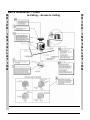
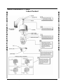
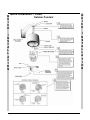
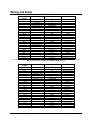
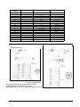
XX134-60-01
Quick Guide for
SurveyorVFT Camera Domes
Warning: To reduce a risk of fire or electric shock, do not expose
the indoor unit to rain or moisture.
Vicon Industries Inc. does not warrant that the functions contained in this equipment will meet your
requirements or that the operation will be entirely error free or perform precisely as described in the
documentation. This system has not been designed to be used in life-critical situations and must not be
used for this purpose.
Copyright © 2007 Vicon Industries Inc. All rights reserved.
Product specifications subject to change without notice.
Vicon and its logo are registered trademarks of Vicon Industries Inc.
VICON INDUSTRIES INC., 89 ARKAY DRIVE, HAUPPAUGE, NEW YORK 11788
TEL: 631-952-CCTV (2288) FAX: 631-951-CCTV (2288) TOLL FREE: 800-645-9116
24-Hour Technical Support: 800-34-VICON (800-348-4266)
UK: 44/(0) 1489-566300
WEB: www.vicon-cctv.com
Vicon part number 8009-8134-60-01
Section 3 Rev 108
Important
Safeguards
GRAPHIC SYMBOL EXPLANATION
12. Power Cord Protection - Power supply cords should not
be routed in trafficked areas or in tight spaces where they will
be pinched or used to bear weight. Allow some slack in the
cord where it enters the unit.
13. Outdoor Cable Grounding - Use only grounded outdoor
cables to protect against voltage surges and static charges.
Section 810 of the National Electrical Code, ANSI/NFPA 70-
The lightening bolt symbol alerts the user to the presence of
1984, provides information on proper grounding of the lead-in
dangerous voltage that may present the risk of electric shock.
wire to an antenna discharge unit, size of grounding conductors
and the requirements of grounding electrodes.
14. Lightning - Disconnect the product from its power source
and cable system when possible to prevent damage due to
lightning and power-line surges.
15. Power Lines - Do not locate outside cables over power or
utility lines where they can fall and make direct contact. Contact
with power lines can be fatal.
16. Overloading - Do not overload wall outlets and extension
cords to prevent risk of fire and electric shock.
17. Object and Liquid Entry - Never probe through, or spill
The exclamation point symbol alerts the user to the presence of
liquid into, enclosure openings to prevent risk of fire or electric
important operating and maintenance instructions.
shock.
18. Servicing - Refer all servicing to qualified service
1. Read Instructions - Read all safety and operating
personnel.
instructions before the product is operated.
19. Damage Requiring Service - Obtain service when:
2. Retain Instructions - Retain all safety and operating
instructions for future reference.
a)
The power-supply cord or plug is damaged.
3. Heed Warnings - Pay attention to all product warnings.
b)
Objects have fallen or liquid has been spilled into the
product.
c)
The product is not designed for outdoor use and has been
exposed to water or moisture.
d)
The product does not operate per the operating
instructions. Perform Vicon recommended adjustments,
modifications and troubleshooting only to avoid unit
damage and personal injury.
e)
The product has been dropped.
f)
The product shows a significant change in performance.
20.
Replacement
4. Follow Instructions - Follow all operating instructions.
5. Cleaning -(Do not use caustic, abrasive or aerosol
cleaners)
a)
b)
For units that CAN BE DISCONNECTED from the power
source, use a damp cloth for cleaning.
For units that CANNOT BE DISCONNECTED from the
power source, use a damp cloth for cleaning and do not
allow moisture or liquids to enter vents.
6. Attachments - Use only UL Listed, Vicon recommended
attachments to prevent unit damage and personal injury.
7. Water and Moisture - Use only products designed for
outdoor environments where they will be exposed to water or
moisture.
8. Accessories - Do not place the unit on an unstable surface
to avoid falling. Use only UL Listed Vicon recommended mounting
accessories.
9. Ventilation - Do not block ventilating slots and openings as
they ensure reliable operation. Do not place the unit near a
heat source or into an enclosure unless recommended by
Vicon.
10. Power Sources - The product should only be operated
from the recommended power source. Use only UL Class 2
indoor/dry or Class 3 outdoor/wet power supply.
Contact an electrician to replace an obsolete outlet. Do not
force a plug into a non-grounded outlet.
-
Use
only
Vicon
specified
damage and injury.
21. Safety Check - Request safety checks to be performed
following repair or maintenance to verify proper operation.
22. ESD Precaution - Take all normal electrostatic discharge
precautions to avoid component damage during installation and
operation.
23. For 230 VAC Devices Only - When the disconnect device
is not incorporated in the equipment or when the plug on the
power supply is intended to serve as the disconnect device,
follow the guidelines below:
a)
For permanently connected 230 VAC units, a readily
accessible disconnect device must be incorporated into
11. Grounding - Only products equipped with a 3-prong
grounded plug should be inserted into a grounded power outlet.
Parts
replacement parts or an approved equivalent to prevent unit
the site wiring.
b)
For 230 VAC units with a plug, the outlet must be installed
near the unit and be easily accessible.
Introduction
This Quick Guide provides an overview for installing the standard SurveyorVFT PTZ Camera Dome, the
SVFT-M Impact-Resistant model, the SVFT-PRS Pressurized version and the SurveyorVFT Fixed models
(coaxial, UTP, fiber and ViconNet versions). An abbreviated programming guide is also provided for the
camera domes, excluding the fixed versions. For ViconNet (IP) setup and programming, refer to the VN
Setup section in the complete manual for the specific SurveyorVFT Camera Dome type.
Quick Installation procedures are provided by specific models: standard SurveyorVFT In-Ceiling, Indoor
Pendant and Outdoor Pendant; the SVFT-M; the SVFT-PRS; and the SurveyorVFT Fixed In-Ceiling, Indoor
Pendant and Outdoor Pendant. Be sure to refer to the correct diagram for your particular model and
installation.
Model Family
Standard PTZ
SurveyorVFT In-Ceiling
Standard PTZ
SurveyorVFT Indoor
Pendant
Standard PTZ
SurveyorVFT Outdoor
Pendant
SVFT-M ImpactResistant
SVFT-PRS Pressurized
SVFT-C3312 Fixed
SVFT-P3312 Fixed
SVFT-W3312/
SVFT-W3312DN Fixed
SVFT-W550A/
SVFT-W550DN Fixed
SurveyorVFT Model Families
Description
SVFT-C series; includes 22EX (color ExView), 23X (day/night) and 22X
(color) models available with coaxial, UTP, fiber or ViconNet video
transmission
SVFT-P series; includes 22EX (color ExView), 23X (day/night) and 22X
(color) models available with coaxial, UTP, fiber or ViconNet video
transmission
SVFT-W series; includes 22EX (color ExView), 23X and 35X
(day/night), 22X (color) models available with coaxial, UTP, fiber or
ViconNet video transmission
SVFT-M series; includes 22X (color), 22EX (color ExView), 23X and
35X (day/night) pendant models available with coaxial, UTP, fiber or
ViconNet video transmission
SVFT-PRS series; includes 22EX (color ExView), 23X and 35X
(day/night) pendant models available with coaxial, UTP, fiber or
ViconNet video transmission
SVFT Fixed series; in-ceiling (C) with 3.3-12 mm autoiris varifocal lens
and high-resolution ExView color camera available with coaxial, UTP,
fiber or ViconNet video transmission
SVFT Fixed series; indoor pendant (P) with 3.3-12 mm autoiris varifocal
lens and high-resolution ExView color camera available with coaxial,
UTP, fiber or ViconNet video transmission
SVFT Fixed series; outdoor pendant (W/WDN) with 3.3-12 mm autoiris
varifocal lens and high-resolution ExView color/day/night camera
available with coaxial, UTP, fiber or ViconNet video transmission
SVFT Fixed series; outdoor pendant (W/WDN) with 5-50 mm autoiris
varifocal lens and high-resolution ExView color/day/night camera
available with coaxial, UTP, fiber or ViconNet video transmission
XX134-60-01 Rev 108 SurveyorVFT Camera Dome Quick Guide
Page
2
3
4
5
6
7-8
9
10
10
Introduction • 1
Q
U
I
C
K
Quick Installation – Standard PTZ In-Ceiling Model
I
N
S
T
A
L
L
A
T
I
O
N
Q
U
I
C
K
I
N
S
T
A
L
L
A
T
I
O
N
2 • Introduction
XX134-60-01 Rev 108 SurveyorVFT Camera Dome Quick Guide
Q
U
I
C
K
Quick Installation – Standard PTZ Indoor Pendant
I
N
S
T
A
L
L
A
T
I
O
N
XX134-60-01 Rev 108 SurveyorVFT Camera Dome Quick Guide
Q
U
I
C
K
I
N
S
T
A
L
L
A
T
I
O
N
Introduction • 3
Quick Installation – Standard PTZ Outdoor Pendant
Q
U
I
C
K
Q
U
I
C
K
I
N
S
T
A
L
L
A
T
I
O
N
I
N
S
T
A
L
L
A
T
I
O
N
4 • Introduction
XX134-60-01 Rev 108 SurveyorVFT Camera Dome Quick Guide
Q Quick Installation – SVFT-M Impact-Resistant
U
I
C
K
Q
U
I
C
K
I
N
S
T
A
L
L
A
T
I
O
N
I
N
S
T
A
L
L
A
T
I
O
N
XX134-60-01 Rev 108 SurveyorVFT Camera Dome Quick Guide
Introduction • 5
Quick Installation – SVFT-PRS Pressurized
Q
U
I
C
K
Q
U
I
C
K
I
N
S
T
A
L
L
A
T
I
O
N
I
N
S
T
A
L
L
A
T
I
O
N
6 • Introduction
XX134-60-01 Rev 108 SurveyorVFT Camera Dome Quick Guide
Quick Installation – Fixed
Q
U
I
C
K
In Ceiling, No Access to Ceiling
Q
U
I
C
K
I
N
S
T
A
L
L
A
T
I
O
N
XX134-60-01 Rev 108 SurveyorVFT Camera Dome Quick Guide
I
N
S
T
A
L
L
A
T
I
O
N
Introduction • 7
Quick Installation – Fixed
In-Ceiling – Access to Ceiling
Q
U
I
C
K
Q
U
I
C
K
I
N
S
T
A
L
L
A
T
I
O
N
I
N
S
T
A
L
L
A
T
I
O
N
8 • Introduction
XX134-60-01 Rev 108 SurveyorVFT Camera Dome Quick Guide
Quick Installation – Fixed
Q
U
I
C
K
Indoor Pendant
Q
U
I
C
K
I
N
S
T
A
L
L
A
T
I
O
N
XX134-60-01 Rev 108 SurveyorVFT Camera Dome Quick Guide
I
N
S
T
A
L
L
A
T
I
O
N
Introduction • 9
Q
U
I
C
K
Quick Installation – Fixed
Outdoor Pendant
I
N
S
T
A
L
L
A
T
I
O
N
I
N
S
T
A
L
L
A
T
I
O
N
10 • Introduction
Q
U
I
C
K
XX134-60-01 Rev 108 SurveyorVFT Camera Dome Quick Guide
Wiring and Setup
Pin Connections – Standard SurveyorVFT and SVFT-M
CONNECTOR/PIN
NUMBER
CONNECTOR TYPE
CONNECTOR/PIN LABEL
SIGNAL NAME
BNC (female)
VIDEO (J1)
VIDEO
J2
Video output
J1
AMP Header
(Fiber Optic board)*
TERMINAL BLOCK
J2
Video/RS-422 data
POWER (TB1)
TB1-1
Hot
H
N
TB1-2
Neutral
TERMINAL BLOCK
ALARM (TB2)
TB2-1
Alarm input 1
ALARM 1
TB2-2
Ground
GND
TB2-3
Alarm input 2
ALARM 2
TB2-4
Ground
GND
TB2-5
Alarm input 3
ALARM 3
TB2-6
Ground
GND
TB2-7
Alarm input 4
ALARM 4
GND
TB2-8
Ground
TERMINAL BLOCK
COMM/RELAY (TB3)
TB3-1
Command in +
COMM IN +
TB3-2
Command in COMM IN TB3-3
Response out +
RESP OUT +
TB3-4
Response out RESP OUT TB3-5
Ground
GND
TB3-6
Relay, common
RELAY C
TB3-7
Relay, normally open
RELAY NO
RELAY NC
TB3-8
Relay, normally closed
*J2 for optional fiber optics interface board that provides video and RS-422 full duplex data through a standard fiber optics connector.
Wiring Connections – Standard Coaxial/Fiber Optic Versions
CONNECTOR/PIN
NUMBER
CONNECTOR TYPE
CONNECTOR/PIN LABEL
TERMINAL BLOCK
VIDEO NVT (TB4)
UTP +
UTP GND
POWER (TB1)
H
N
ALARM (TB2)
ALARM 1
GND
ALARM 2
GND
ALARM 3
GND
ALARM 4
GND
COMM/RELAY (TB3)
COMM IN +
COMM IN RESP OUT+
RESP OUT GND
RELAY C
RELAY NO
RELAY NC
TB4-1
TB4-2
TB4-3
TERMINAL BLOCK
TB1-1
TB1-2
TERMINAL BLOCK
TB2-1
TB2-2
TB2-3
TB2-4
TB2-5
TB2-6
TB2-7
TB2-8
TERMINAL BLOCK
TB3-1
TB3-2
TB3-3
TB3-4
TB3-5
TB3-6
TB3-7
TB3-8
XX134-60-01 Rev 108 SurveyorVFT Camera Dome Quick Guide
SIGNAL NAME
Unshielded twisted pair +
Unshielded twisted pair -
Hot
Neutral
Alarm input 1
Ground
Alarm input 2
Ground
Alarm input 3
Ground
Alarm input 4
Ground
Command in +
Command in Response out+
Response out Ground
Relay, common
Relay, normally open
Relay, normally closed
Wiring and Setup • 11
Wiring Connections – UTP Version
12 • Wiring and Setup
XX134-60-01 Rev 108 SurveyorVFT Camera Dome Quick Guide
CONNECTOR/PIN
NUMBER
CONNECTOR TYPE
CONNECTOR/PIN LABEL
TERMINAL BLOCK
POWER (TB3)
H
N
ALARM (P1)
ALARM OUT
GND
ALARM IN
LAN (J7)
TX +
TX RX +
POE POWER
POE POWER
RX POE POWER
POE POWER
TB3-1
TB3-2
TERMINAL BLOCK
P1-1
P1-2
P1-3
RJ-45
J7-1
J7-2
J7-3
J7-4
J7-5
J7-6
J7-7
J7-8
1/8-IN. PHONO
J3
J6
AUDIO
MIC
SPK
SIGNAL NAME
Hot
Neutral
Alarm output
Ground
Alarm input
Transmit +
Transmit Receive +
PoE Power
PoE Power
Receive PoE Power
PoE Power
Audio In
Audio Out - N/A
Wiring Connections – ViconNet Version
Pin Connections – SVFT-PRS
Prefabricated cable
Customer prepared cable→
On coaxial and UTP units, L, M, X and U are not used.
On fiber units L, M, J, K, X and U are not used.
On ViconNet units, A, C, D, P, T, L, M, J, K. X, and U are not used.
XX134-60-01 Rev 108 SurveyorVFT Camera Dome Quick Guide
Wiring and Setup • 13
Pin Connections – SurveyorVFT Fixed
Both power and video connections are made to the integral printed circuit board (PC board) on the camera
mechanism. The PC board provides a board-mounted BNC connector for coaxial, a screw terminal for twisted
pair video, an ST connector for fiber-optic or an RJ-45 connector on the ViconNet board for video connection
and a removable two-position screw terminal connector for camera power.
DIP Switch Settings
The address and mode are set using the two 8-position DIP Switch banks SW1 and SW2. DIP switch 1
(SW1) is used to set the address. DIP switch 2 (SW2) is used to set the mode functions and protocol. Refer
to the Configuration section of the manual for details.
14 • Wiring and Setup
XX134-60-01 Rev 108 SurveyorVFT Camera Dome Quick Guide
Programming the SurveyorVFT
Programming is done by selecting options from the on-screen menu system using the AP (autopan), AI
(autoiris), joystick and AUX1/AUX2 functions. The cursor wraps around when moving up and down. The
following is a description of these controls:
AP: select and store parameters; go forward through the menu system.
AI:
leave or exit a menu without retaining the new setting.
Joystick Left/Right:
select specific program parameters.
AUX 1, AUX 2and AUX 3:
used for very specific menu functions detailed in the menu system.
Six functions are carried out using only keypad controls, setting autopan limits, programming continuous
rotation, selecting the autopan speed, programming sectors, polarity of response lines, enabling auto-baud
detect and setting manual pan limits.
Software Features
Most of the SurveyorVFT features are accessed remotely through either a System Console (V1400X-DVC-3),
keypad (V1410X-DVC, V1411X-DVC, V1411J-DVC, V1300X-RVC rack mount or V1300X-DVC desktop) or a
PC using the SurveyorVFT Configurator software package. To program certain features, a numeric preset is
either stored or recalled. Preset functions can represent a variety of features.
PRESET
NUMBER
1 to 79
80 to 87
88 to 89
90
93
94
95
96
97
98
99
FUNCTION
Preset positions
Tour sequences
Autotour sequences
Pan/Tilt lockout
Set response line polarity
Enter Dome menu system
Auto-Baud Detect feature
Program Dome sectors
Initiate Dome reset
Autopan limits
Set manual pan limits
The table on the left shows preset numbers and their functions,
which are described in detail below. There are no commands
associated with certain presets. These have been reserved for
future use or advanced programming and diagnostic tools.
Preset 1-79 (Preset Positions) — When a preset number is stored,
the current position of the camera is written into that preset memory
location. When the number is recalled, the camera moves to the
stored position. This is called solving a preset.
Presets are usually solved at the maximum speed, typically less
than 1 second; if a preset is assigned to a tour or salvo, the preset
recall speed is programmable. Camera focus is also stored as part
of the preset; if the image is out of focus when the preset is stored,
it will be out of focus when the preset is solved, even if autofocus is
enabled.
When a preset is recalled, the corresponding preset title is
displayed on the screen (when preset titles have been enabled). If the operator attempts to recall a preset
number that has not been stored, the message “Preset Not Stored” appears on the screen for a short period
and the camera position does not change. Pressing any command key or moving the joystick will also remove
the message.
Preset 80-87 (Tour Sequences) — A tour is a series of up to 32 events or actions. Accessing the “Program
Tour” option will bring up an on-screen menu that allows programming of each tour event. Recalling a tour
initiates the sequence of events that corresponds to that tour number. A longer sequence of actions can be
prepared by chaining 2 or more tours together.
Preset 88-89 (Autotour Sequences) — An Autotour is a series of up to 256 pan, tilt and zoom actions.
Accessing the “Program Autotour” option will bring up an on-screen menu which allows dynamic
programming of each autotour event.
Preset 90 (Pan/Tilt Lockout) — Storing preset 90 will disable joystick control of that dome, and the message
Pan/Tilt Disabled will momentarily appear on the screen. Any time the joystick is moved, the message will
reappear. To restore pan/tilt operation, preset 90 must be stored again.
This feature prevents the camera dome’s position from being tampered with. This allows the dome to respond
only to preset positions, eliminating the operator’s ability to manually position the dome. It also allows a unit to
be temporarily locked onto a subject for recording or monitoring specific activity. Recalling preset 90 has no
effect. The camera dome retains its capability of zoom, focus and iris control while locked.
XX134-60-01 Rev 108 SurveyorVFT Camera Dome Quick Guide
Wiring and Setup • 15
Preset 93 (Set Response Line Polarity) (Duplex Only) — The SurveyorVFT checks for polarity of the
command in lines through the auto baud detect feature. The baud detect cycles through 4800+/4800/9600+/9600-/19200+/19200-, indicating not only the baud rate it is searching for but also the polarity that the
receive lines are set to. When preset 93 is selected, the dome will periodically cycle the polarity of the COMM
IN+ and COMM IN- lines. During the cycling, pan the joystick and press either the A/I or A/P key. As soon as
one of the respective lights illuminates, press the AUX2 key. This locks in the correct polarity for operation.
Preset 94 (Enter Dome Menu System) — Many SurveyorVFT features are accessed through a series of onscreen menus. These are accessed by storing preset 94. Recalling preset 94 has no effect. For convenience,
when performing programming, pressing the L-SPD (lens speed) button will display a black background.
Preset 95 (Auto-Baud Detect Feature) — Auto-baud detect functions after installing defaults, using preset
95, when switching Vicoax to NOVA (VPS) and upon power-up when the dome sees an incorrect baud rate
from keypad or control system. It allows the camera dome to detect a new baud rate from the host controller
without having to fully reboot the camera dome and lose all stored configuration parameters. Be sure that
auto home on power up is disabled before executing this command. Symbols are used to display the status of
the detection process. The * symbol indicates that valid data at the correct baud rate has been received, the
X symbol represents a framing error has been received and the - symbol indicates that no data has been
received. Recalling preset 95 has no effect.
Preset 96 (Program Dome Sectors) — The SurveyorVFT has the ability to divide its 360° field-of-view into
sections or sectors. There may be up to 16 sectors and the boundaries for each are programmed for each
individual dome. An individual title may be programmed for each sector and video may be enabled or
disabled.
Storing preset 96 will begin the sector programming process by establishing the left boundary for sector 1.
Pan the camera to the right and press the AP (autopan) key to set the right boundary for sector 1, which is
also the left boundary of sector 2. Continue panning the camera and pressing AP until all 16 boundaries have
been programmed. If fewer than 16 sectors are required, press AP repeatedly at the right boundary of the last
sector you will be programming to use up all the boundary numbers and exit sector-programming mode.
When the camera is moved, the corresponding sector title is displayed on the screen (when sector titles have
been enabled). If the video is disabled for a given sector, a black screen with the words “Blank Sector” will
appear when the camera enters that sector and video will be restored when the camera moves to a sector
where video is enabled. Sector programming can be aborted by issuing a preset recall; this will also erase
any prior sector programming. Recalling preset 96 has no effect.
Preset 97 (Initiate Dome Reset) — Storing preset 97 resets all of the system software and performs the
power-on self-test. This is called a “soft reset” because no memory settings are affected. All user
programmed options such as titles and presets remain unchanged. Recalling preset 97 has no effect.
Preset 98 (Programming Autopan Limits) — When a SurveyorVFT is selected on a keyboard, pressing the
AP (autopan) key will start the camera in motion, panning at a predetermined speed.
•
To change the speed — Press and hold the AP key while moving the joystick to the desired speed.
When the speed is correct, release the AP button and then the joystick. Each dome may have its own
autopan speed and pressing the autopan key will start the dome panning at the last speed selected for
that dome. (When using a Kollector DVR, shut off AP, move the slider to desired speed and press AP
again.) In continuous rotation only, the autopan command will cause the dome to reverse direction.
•
To stop autopanning — Any other pan command will disable autopan. This includes pressing the AP
key again, panning the camera with the joystick, or recalling a preset.
•
To set the autopan limits — When a continuous rotation dome is in autopan, it will rotate in a full
circle until autopan is disabled. When an application, such as a wall-mounted camera on a building,
does not require continuous rotation, limits are set to define the left and right boundaries. Storing
preset 98 will bring up a series of prompts to set the left and right autopan limits with the AUX 2 and
AUX 3 keys. When the autopan limits are set and the camera is placed into autopan it will pan until it
reaches a limit. It will then reverse direction until it reaches the opposite limit, repeating this cycle
indefinitely.
16 • Wiring and Setup
XX134-60-01 Rev 108 SurveyorVFT Camera Dome Quick Guide
•
To clear the autopan limits — Store preset 98. Press AUX 2 and AUX 3 without panning to set the
autopan limits to the same position. By recording both limits on the same point they will both be
deleted. The dome will now rotate continuously when placed in autopan mode until new limits are
programmed.
Recalling presets 98 has no effect.
Preset 99 (Set Manual Pan Limits) — Storing preset 99 will bring up a series of prompts to set the left and
right manual pan limits with the AUX 2 and AUX 3 keys. After these are set, the physical range between these
limits is the valid range. The camera dome will not move outside these limits. Setting pan limits also sets AP
limits if the AP limits are outside the of the pan limits. The only exceptions are prerecorded tours and
previously stored presets. To clear the pan limits, press AUX 2 and AUX 3 without panning.
Programming Menus
The Main Programming Menu is the first one seen when entering programming mode (store preset 94).
Subsequent menus, called sub-menus are accessible from this point. When in
programming mode, a function is entered by pressing the AP (autopan) key.
To back out of that function without changes, press the AI (autoiris) key.
Instructions are available on the screen for almost all functions. For
convenience, press the L-SPD (lens speed) button to display a black
background.
The selections available on this menu can be summarized as follows:
System Settings — Allows the user to adjust the speed of the pan and tilt
axes. Solving preset positions is always done at full speed. This menu also controls the Zoom Scalable
Pan/Tilt, Compass, PTZ TImeout and Flip features.
Camera Controller — Permits user adjustment of the advanced video features available on the
SurveyorVFT.
Alarm Handling — Configures the SurveyorVFT’s four alarm inputs.
Relay Driver — Adjusts and configures the relay output for control of external devices.
Source Titling — Programs and displays the various titles available to the SurveyorVFT.
Note: All titles are disabled from the factory and will not be displayed upon initial startup.
Preset/Tour Handling — Programs preset events into the camera dome. It also allows programming a series
of events or actions into a script called a Tour and Autotour and on 23X/35X versions, Motion Detection zone
set up.
Scheduler/Time of Day — The Scheduler provides a means of programming events to occur at specific
times of the day. The Time of Day feature allows programming of the time display format. It allows selection
of daylight saving time, 12/24-hour format and actual setting of the time and date.
Language — Programs language format for titles and menus. Language choices are English, Spanish,
French, German and Italian. The word “Language” will continuously change between the five translated
words, Language, Idioma, Langue, Sprache and Lingua, to alert an operator that this prompt is related to
changing the language. When selected, the menus will immediately display the new language.
Install Defaults — Resets the SurveyorVFT to the factory default settings. All previously programmed titles
and settings are lost when this function is accessed, so keep a record of programmed settings. The main
default settings are listed in the Install Defaults section. Some default settings are camera dependent; those
are not listed.
Note: On unit power up, when DIP switch SW2 positions 2, 6, 7 and 8 are all set to ON, the unit will perform
an Install Defaults.
XX134-60-01 Rev 108 SurveyorVFT Camera Dome Quick Guide
Wiring and Setup • 17
Vicon Standard Equipment Warranty
Vicon Industries Inc. (the “Company”) warrants your equipment to be free from defects in material and workmanship under
Normal Use from the date of original retail purchase for a period of three years, with the following exceptions:
1.
2.
3.
4.
5.
VCRs, all models: Labor and video heads warranted for 120 days from date of original retail purchase. All other
parts warranted for one year from date of original retail purchase.
Video monitor CRT (cathode ray tube) and LCD monitors, all models: One year from date of original retail
purchase.
Uninterruptible Power Supplies: Two years from date of original retail purchase.
VDR-304 and VDR-308 Recorder Series: One year from date of original retail purchase.
Normal Use excludes prolonged use of lens and pan-and-tilt motors, gear heads, and gears due to continuous
use of “autopan” or “tour” modes of operation. Such continuous operation is outside the scope of this warranty.
Date of retail purchase is the date original end-user takes possession of the equipment, or, at the sole discretion of the
Company, the date the equipment first becomes operational by the original end-user.
The sole remedy under this Warranty is that defective equipment be repaired or (at the Company’s option) replaced, at
Company repair centers, provided the equipment has been authorized for return by the Company, and the return shipment
is prepaid in accordance with policy.
The Company will not be obligated to repair or replace equipment showing abuse or damage, or to parts which in the
judgment of the Company are not defective, or any equipment which may have been tampered with, altered, misused, or
been subject to unauthorized repair.
Software supplied either separately or in hardware is furnished on an “As Is” basis. Vicon does not warrant that
such software shall be error (bug) free. Software support via telephone, if provided at no cost, may be
discontinued at any time without notice at Vicon’s sole discretion. Vicon reserves the right to make changes to
its software in any of its products at any time and without notice.
This Warranty is in lieu of all other conditions and warranties express or implied as to the Goods, including any
warranty of merchantability or fitness and the remedy specified in this Warranty is in lieu of all other remedies
available to the Purchaser.
No one is authorized to assume any liability on behalf of the Company, or impose any obligations on it in connection with
the sale of any Goods, other than that which is specified above. In no event will the Company be liable for indirect, special,
incidental, consequential, or other damages, whether arising from interrupted equipment operation, loss of data,
replacement of equipment or software, costs or repairs undertaken by the Purchaser, or other causes.
This warranty applies to all sales made by the Company or its dealers and shall be governed by the laws of New York
State without regard to its conflict of laws principles. This Warranty shall be enforceable against the Company only in the
courts located in the State of New York.
The form of this Warranty is effective August 15, 2007.
THE TERMS OF THIS WARRANTY APPLY ONLY TO SALES MADE WHILE THIS WARRANTY IS IN EFFECT. THIS
WARRANTY SHALL BE OF NO EFFECT IF AT THE TIME OF SALE A DIFFERENT WARRANTY IS POSTED ON THE
COMPANY’S WEBSITE, WWW.VICON-CCTV.COM. IN THAT EVENT, THE TERMS OF THE POSTED WARRANTY
SHALL APPLY EXCLUSIVELY.
Vicon Part Number: 8006-9010-03-03 Rev 807
18 • Vicon Standard Equipment Warranty
XX134-60-01 Rev 108 SurveyorVFT Camera Dome Quick Guide
Vicon Industries Inc.
Corporate Headquarters
89 Arkay Drive
Hauppauge, New York 11788
631-952-CCTV (2288) 800-645-9116
Fax: 631-951-CCTV (2288)
Vicon Europe
Headquarters
Brunel Way
Fareham, PO15 5TX
United Kingdom
+44 (0) 1489 566300
Fax: +44 (0) 1489 566322
Germany
vin-videotronic infosystems gmbh
Lahnstrasse 1
D-24539 Neumuenster
Phone: +49 (0) 4321 8790
Fax: +49 (0) 4321 879 47
Far East Office
Unit 5, 17/F, Metropole Square
2 On Yiu Street, Shatin
New Territories,
Hong Kong
(852) 2145-7118
Fax: (852) 2145-7117
Internet Address: www.vicon-cctv.com