1
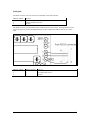
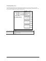
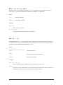
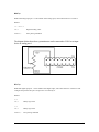
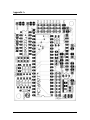
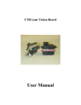
Personal Rover Project
Cerebellum Board
User’s Manual
Revision date: 1/29/02
Introduction
The Cerebellum is intended as the main controller board for the Personal Rover. Built around PIC
microcontroller, it provides the following functionality:
•
•
•
•
•
•
•
•
Controls up to 8 hobby servos
Open loop control of 2 DC motors
Read from up to 8 analog input lines at 8-bit resolution
4 digital I/O lines
2 RS232 serial communications ports
I2C bus master for up to 8 motor controller daughterboards
ASCII-based serial user interface
User programmable over PC parallel port
Hardware
The following is a list of the main parts that are needed for assembling the Cerebellum.
Quantity
1
1
1
1
1
1
1
1
4
1
1
1
2
1
2
5
1
1
1
1
1
1
2
Item
Cerebellum printed circuit board
Microchip PIC16F877
Maxim MAX232
Allegro UDN2998
LM2940 voltage regulator
ECS ZTT 20MHz crystal resonator
2N4400 NPN transistor
100uF electrolytic capacitor
1uF tantalum capacitor
0.22uF ceramic capacitor
0.1uF ceramic capacitor
47pF ceramic capacitor
100kohm resistor
4.7kohm resistor
2.2kohm resistor
1kohm resistor
220ohm resistor
3mm LED
SPST switch
40-pin DIP socket
16-pin DIP socket
2-pin polarized pin header
3-pin polarized pin header
Single row male headers
Dual row male headers
Dual row female headers
Part no. (Digikey unless specified)
Unit Price
PIC16F877-20/P-ND
MAX232CPE-ND
09F1716 (Newark)
LM2940CT-5.0-ND
X909-ND
2N4400-ND
P5138-ND
P2105-ND
P4966-ND
P4924-ND
P4845-ND
100KQBK-ND
4.7KQBK-ND
2.2KQBK-ND
1.0KQBK-ND
220QBK-ND
350-1365-ND
EG1847-ND
ED3640-ND
ED3316-ND
WM2700-ND
WM2701-ND
929400-01-36-ND
929836-09-36-ND
929975-01-36-ND
8.98
3.31
6.03
1.80
0.81
0.27
0.28
0.42
0.55
0.43
0.38
0.24
0.24
0.24
0.24
0.24
0.60
1.11
2.09
0.83
0.58
0.90
0.96
2.02
2.04
The PCB layout diagram can be found in Appendix A.
1
Power
The Cerebellum has a voltage regulator that provides a stable 5V to its logic systems and integrated
circuits. This means that more than 5V has to be supplied to the primary power input to provide for the
dropout voltage of the regulator.
Both the H-bridge and the hobby servos can be powered through either the main power supply or their own
independent power supplies. This is selected using jumpers on JP1 and JP2 respectively.
The following diagrams and tables show the pin numbering and appropriate jumper connections for JP1,
JP2, PWR1, PWR2 and PWR3.
PWR1 pin number
1
2
Connection
Positive power
Ground
JP1 connections
Pins 1 & 2
Pins 2 & 3
Function
DC motors draw power from PWR1
DC motors draw power from PWR2
PWR2 pin number
1
2
Connection
Positive H-bridge power
Ground
JP2 connections
Pins 1 & 2
Pins 2 & 3
Function
Hobby servos draw power from PWR1
Hobby servos draw power from PWR3
PWR3 pin number
1
2
Connection
Ground
Positive hobby servo power
The voltage supplied to the primary power input should be at least 6V, to supply regulated power to the
various ICs. Preferably 8-12V should be supplied so that voltage regulation can be maintained during
spikes and transients caused by motors. There is a limit of 25V, imposed by the specifications of the
voltage regulator. A higher supply voltage is required if you’re using a regular voltage regulator (eg.
78LS05) instead of a low dropout regulator (LM2940). It should also be higher if the H-bridge was drawing
its power from the primary input instead of from its own auxiliary power input. In this case, the voltage
supplied to the primary input should be however much the DC motors require.
2
Serial ports
The SER1 connector is used to connect the Cerebellum to the camera module.
SER1 pin number
1
2
3
Purpose
Camera receive, PIC transmit
Camera transmit, PIC receive
Ground
The SER2 connector is used for RS232 serial communications with a host PC. The diagram below shows
the wiring required to connect the SER2 serial port on the Cerebellum to a DB-9 connector on a serial
cable.
SER2 pin number
1
2
3
DB9 pin number
2
3
5
Purpose
PC receive, PIC transmit
PC transmit, PIC receive
Ground
3
Connecting hobby servos
The following diagram shows the pin numberings for the bank of 8 servo motor connectors. The cable
colors correspond to those found on standard Futaba hobby servos. Each connector, from SV0 to SV7, can
be connected to one hobby servo, giving a total of 8 servos.
SV[0..7] pin number
1
2
3
Purpose
PWM control signal
Positive power supply
Ground
4
I/O connector
CON1 is the auxiliary I/O connector. It contains the Cerebellum’s analog input and digital I/O lines. It also
provides power supply pins for these additional circuits. The diagram below shows the pin numbering order
for CON1. The pins are numbered such that odd numbered pins are below and even numbered pins are
above.
CON1 pin number
1
2
3
4
5
6
7
8
9
10
11
12
13
14
15
16
Purpose
Ground
Positive power supply from PWR1 (unregulated)
Ground
+5V (regulated)
Analog input port 0
Analog input port 1
Analog input port 2
Analog input port 3
Analog input port 4
Analog input port 5
Analog input port 6
Analog input port 7
Digital I/O port 0
Digital I/O port 1
Digital I/O port 2
Digital I/O port 3
5
I2 C connector
The diagram below shows the pin numbering order for CON2, the I2C bus connector.
CON2 pin number
1
2
3
4
Purpose
PWR
GND
I2 C clock line (SCK)
I2 C data line (SDA)
Programming connector
The following diagram shows the wiring necessary for connecting the programming connector (CON3) to
the 25-pin connector of a PC’s parallel port.
CON3 pin number
1
2
3
4
5
6
7
8
DB25 pin number
25
2
4
5
3
10
Purpose
Ground
Programming Data In
Programming Clock
Memory Clear (Reset)
Enter Low Voltage Programming Mode
Programming Data Out
Not connected
Not connected
6
Software
Once the board has been assembled and powered up, firmware can be downloaded onto the
microcontroller. Both firmware (HEX file) and downloader (DLPIC) can be downloaded from
http://www.cs.cmu.edu/~myrover/cerebellum/software. If the files have been
downloaded into the c:\cerebellum directory, the following command downloads the HEX file
SUI.HEX onto the PIC.
C:\CEREBELLUM\>dlpic sui.hex
The download program will inform the user of its successful completion. Once the serial user interface
firmware has been downloaded, the board is ready for use. To boot up the Cerebellum, connect up the
power and serial connectors and switch the power switch to its ON position. The indicator LED on the
upper left hand corner (PWRLED) should light up. Remember to disconnect the programming connector
(CON3).
Serial User Interface
The Cerebellum uses the SER2 serial port for communications with a host computer. This port can operate
at baud rates of 9600, 19200 or 38400bps. The default speed is 38400bps. Communications parameters are
as follows:
•
•
•
•
8 data bits
No parity bit
1 STOP bit
No flow control
Running a serial terminal program on the host computer while turning on the Cerebellum should give the
following boot-up message from the microcontroller:
Cerebellum Serial Interface v0.9 22-Aug-01
OK
This shows that the firmware has been downloaded properly, and serial communications are working. The
Cerebellum should now respond to commands sent to it over this serial link. As a further check, the
Cerebellum should echo all characters that it receives, so the “local echo” option on the PC’s terminal
program should be turned off.
Serial Command Set
All received commands will be converted into uppercase before processing, so command processor
becomes case insensitive. Whitespace is optional where other separators and delimiters already exist.
Where one space can exist, multiple spaces will also be accepted. All commands shall be terminated by a
carriage return character (“\r”, ASCII 13).
All commands will return "OK\r", "ERROR\r" or "TIMEOUT\r" as their final status, and no further user
input will be read until then.
Upon reset, the current firmware version and EEPROM settings will be displayed. Typing "?\r" at the
beginning of a line will display a command summary.
7
SV[n] [+|-]m [[+|-]m ...]\r
Hobby servo command. n is the number of a specific servo, and can range from 0 to 7 inclusive. m from 0
to 255 inclusive. Maximum of 8 servo movement parameters. A + or - prefix will cause m to be interpreted
as a relative increment or decrement from the servo's current position. Position 0 disables the particular
servo, position 128 being the servo's center position. At startup, all servos are disabled.
Returns:
OK\r
Commmand completed
ERROR\r
Error parsing command
Examples:
SV5 30\r
Servo 5 to position 30
SV0 +10\r
Servo 0 increment by 10
SV7 -67\r
Servo 7 decrement by 67
SV 5 +4 -12\r
Servo 0 to position 5, servo 1 increment 4, servo 2 decrement 12
SV 0 0 0 0 +15 -27 +2 50\r
Servos 0 thru 3 disable, servo 4 increment 15, 5 decrement 27, 6 increment 2, 7 position 50
8
MT[n] [+|-]m [[+|-]m]\r
DC motor control. n is the number of a DC motor (0 or 1). m is PWM duty-cycle, 0 being off, 255 begin
100%. The + or - prefix controls the direction of the motor, defaults to + if unspecified.
Returns:
OK\r
Command completed
ERROR\r
Error parsing command
Examples:
MT1 100\r
motor 1, forward, speed 100
MT 250 -50\r
motor 0 forward, speed 250, motor 1 reverse, speed 50.
DBn [d ...]\r
Daughterboard command. n is the number of a specific daughterboard, valid values from 0 to 7 inclusive. d
is a data byte that is to be sent to the daughterboard, in decimal form, 0 to 255 inclusive. Response packet
will only be read from daughterboard if data bytes are sent.
Returns:
<daughterboard response>\r
OK\r
Command completed
NACK\r
NACK received during I2C transmission
ERROR\r
Error parsing command
Examples:
DB3 15 27 230 0\r
open i2c communications to daughterboard 3, sends data bytes 15, 27, 230, 0
DB0\r
checks for presence of daughterboard 0, returns OK if daughterboard ACKs address byte that was
transmitted over I2C, NACK if no daughterboard responds to address 0.
9
SS "foo" [Rn]\r
Sends command to the camera, using the secondary serial port. The R option specifies the number of "\r"
delimited lines to echo from camera output, n can range from 1 to 255 inclusive. Camera output is echoed
completely, including the "\r" character. No camera output is echoed if no R option is present. There is a
timeout value between receiving consecutive bytes from the camera.
Returns:
OK\r
Read from camera output completed
TIMEOUT\r
Timeout while waiting for camera output
ERROR\r
Error parsing command
Examples:
SS "foo"
send command foo to camera, no camera output read.
SS"b a r"R4
send command b a r to camera, read 4 lines of output
SSR1
read 1 line of output from camera
TO[n]\r
Set or show camera output timeout, being the maximum idle time between 2 consecutive bytes of camera
output. n is the timeout value in 10s of milliseconds, ranging from 0 to 255 inclusive, and takes effect
immediately. It will be stored into EEPROM and still be in effect after a reset. A value of 0 would indicate
an infinite timeout. If n is not specified, returns the current timeout value.
Returns:
OK\r
Command completed, timeout value set
[0..255]\r
OK\r
Current timeout value, in ms.
ERROR\r
Error parsing command
10
ANn\r
Read from analog input port. n is the number of the analog input, valid values from 0 to 7 inclusive.
Returns:
<0..255>\r
OK\r
Digitized analog value
ERROR\r
Error parsing command
The diagram below shows how a potentiometer can be connected to CON1 as an input
device to analog port 0.
DIn\r
Read from digital input port. n is the number of the digital input, valid values from 0 to 7 inclusive. Will
configure the specified I/O pin as an input if it is not already so.
Returns:
0\r
OK\r
Binary logic value
1\r
OK\r
Binary logic value
ERROR\r
Error parsing command
11
DHn\r
Output high from digital output port. n is the number of the digital input, valid values from 0 to 7 inclusive.
Will configure the specified I/O pin as an output if it is not already so.
Returns:
OK\r
Command completed
ERROR\r
Error parsing command
DLn\r
Output low from digital output port. n is the number of the digital input, valid values from 0 to 7 inclusive.
Will configure the specified I/O pin as an output if it is not already so.
Returns:
OK\r
Command completed
ERROR\r
Error parsing command
12
BR<9600|19200|38400>\r
Sets baud rate of PC serial communications port (SER2). New baud rate will be stored into EEPROM and
will only take effect after a reset.
Returns:
OK\r
Command completed
ERROR\r
Error parsing command
VER\r
Dis plays cerebellum firmware version number.
Returns:
Cerebellum Serial Interface v1.0\r
OK\r
Command completed
13
Appendix A
14
15