1
Instruction Manual
Model 4500: 4.5" Equatorial Reflecting Telescope
M
E
A
D
E
PRODUCTS
30
90
ADVANCED
0
60
90 60
30
DIVISION
Meade Instruments Corporation
World’s Leading Manufacturer of Astronomical Telescopes for the Serious Amateur
6001 Oak Canyon, Irvine, California 92618 ■ (949) 451-1450
FAX: (949) 451-1460 ■ www.meade.com
© 1995
Rev. B
4/95
–2–
WARNING
NEVER ATTEMPT TO OBSERVE THE SUN THROUGH YOUR MEADE
TELESCOPE! OBSERVING THE SUN, EVEN FOR THE SHORTEST
FRACTION OF A SECOND, WILL CAUSE INSTANT AND IRREVERSIBLE
EYE DAMAGE. WHEN OBSERVING DURING THE DAYTIME, DO NOT
POINT THE TELESCOPE EVEN CLOSE TO THE SUN.
Meade Limited Warranty
Every Meade telescope, spotting scope, and binocular is warranted by Meade Instruments Corp. (MIC) to be free of defects in materials
and workmanship for a period of ONE YEAR from date of original retail purchase in the U.S.A. MIC will repair or replace the product,
or part thereof, found upon inspection by MIC to be defective, provided the defective part or product is returned to MIC, freight prepaid,
with proof of purchase. This warranty applies to the original purchaser only and is non-transferable. Meade products purchased outside
North America are not included in this warranty, but are covered under separate warranties issued by Meade International Distributors.
RGA Number Required: Prior to the return of any product or part, a Return Goods Authorization (RGA) number must be obtained by
writing to MIC or calling 949-451-1450. Each returned part or product must include a written statement detailing the nature of the
claimed defect, as well as the owner’s name, address, phone number, and a copy of the original sales invoice.
This warranty is not valid in cases where the product has been abused or mishandled, where unauthorized repairs have been attempted
or performed, or where depreciation of the product is due to normal wear-and-tear. MIC specifically disclaims special, indirect, or
consequential damages or lost profit, which may result from a breach of this warranty. Any implied warranties which can not be
disclaimed are hereby limited to a term of one year from the date of purchase by the original retail purchaser.
This warranty gives you specific rights. You may have other rights which vary from state to state.
MIC reserves the right to change product specifications or to discontinue products without prior notice.
This warranty supersedes all previous Meade product warranties.
–3–
TABLE OF CONTENTS
A. Introducing the Meade Model 4500 . . . . . . . . . . . . . . . . . . . . . . . . . .6
1. This Manual . . . . . . . . . . . . . . . . . . . . . . . . . . . . . . . . . . . . . . . . .6
2. Standard Equipment . . . . . . . . . . . . . . . . . . . . . . . . . . . . . . . . . .6
B. Unpacking and Assembly . . . . . . . . . . . . . . . . . . . . . . . . . . . . . . . . . .6
1. Balancing the Telescope . . . . . . . . . . . . . . . . . . . . . . . . . . . . . . .7
2. Alignment of the Viewfinder . . . . . . . . . . . . . . . . . . . . . . . . . . . . .7
C. Understanding Celestial Movements and Coordinates . . . . . . . . . . . .8
D. Lining Up with the Celestial Pole . . . . . . . . . . . . . . . . . . . . . . . . . . . .9
E. Using the Telescope . . . . . . . . . . . . . . . . . . . . . . . . . . . . . . . . . . . . .9
F. Using Setting Circles . . . . . . . . . . . . . . . . . . . . . . . . . . . . . . . . . . . .11
G. Calculating Power . . . . . . . . . . . . . . . . . . . . . . . . . . . . . . . . . . . . . .11
H. Maintenance . . . . . . . . . . . . . . . . . . . . . . . . . . . . . . . . . . . . . . . . . .12
1. Cleaning . . . . . . . . . . . . . . . . . . . . . . . . . . . . . . . . . . . . . . . . . .12
2. Mount and Tripod Adjustments . . . . . . . . . . . . . . . . . . . . . . . . . .12
3. Collimation . . . . . . . . . . . . . . . . . . . . . . . . . . . . . . . . . . . . . . . . .12
a. Correct Collimation . . . . . . . . . . . . . . . . . . . . . . . . . . . . . . .12
b. Spider Vane Adjustments . . . . . . . . . . . . . . . . . . . . . . . . . . .14
c. Diagonal Holder Adjustments . . . . . . . . . . . . . . . . . . . . . . . .14
d. Primary Mirror Adjustments . . . . . . . . . . . . . . . . . . . . . . . . .14
e. Star Testing the Collimation . . . . . . . . . . . . . . . . . . . . . . . . .14
I. Specifications: Model 4500 . . . . . . . . . . . . . . . . . . . . . . . . . . . . . . . .15
J. Optional Accessories . . . . . . . . . . . . . . . . . . . . . . . . . . . . . . . . . . . .15
–4–
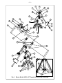
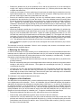
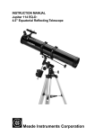
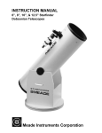
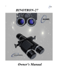
Key to Fig. 1
1. Tripod legs
23. Dec. lock
2. Equatorial mount
24. 6 x 30 viewfinder
3. R.A. flexible cable control
25. Telescope front dust cover
4. Dec. flexible cable control
26. Viewfinder bracket thumbscrews
5. Counterweight
27. R.A. setting circle
6. Counterweight shaft
28. Dec. setting circle
7. Counterweight lock
29. Latitude dial
8. Safety washer/thumbscrew
30. Azimuth lock
9. Latitude lock
31. Focus knobs
10. Polar axis
32. Polar shaft acorn cap nut
11. Latitude adjustment knob
33. Azimuth base
12. Optical tube assembly
34. Azimuth shaft bolt
13. Optical tube saddle plate
35. R.A. worm block assembly
14. Cradle rings
36. Dec. worm block assembly
15. Cradle ring lock knobs
37. Cradle ring attachment knobs
16. Viewfinder bracket mounting bolts
38. Tripod leg Phillips-head fastener screws
17. Focuser
39. Tripod-to-mount attachment points
18. Focuser thumbscrew
40. Accessory shelf
19. Eyepiece
41. Accessory shelf central mounting knob
20. Viewfinder bracket
42. Tripod leg brace supports
21. Declination axis
43. Tripod leg lock knobs
22. R.A. lock
–5–
21
13
23
28
36
10
22
27
32
18
17
19
9
7
35
31
11
33
5
26
25
6
30
24
8
M
E
A
D
E
12
20
34
14
16
15
37
2
30
90
90 60
0
30
60
4
29
3
42
39
38
40
1
41
43
Fig. 1: Meade Model 4500: 4.5" Equatorial Reflecting Telescope
–6–
A. Introducing the Meade Model 4500
The Model 4500 is an easy-to-operate, high performance 4.5" (114mm) reflecting telescope, intended for
astronomical observing. Equipped with a deluxe equatorial mount and aluminum tripod, the telescope’s
motion is continuously adjustable for tracking celestial objects. Your telescope comes to you ready for
adventure; it will be your companion in a universe of planets, galaxies, and stars. Please note that the Model
4500 is a Newtonian reflecting telescope optimized for astronomical observing performance, and is not
intended for terrestrial observing.
1. This Manual
These instructions detail the set-up, operation, specifications, and optional accessories of your Meade
Model 4500. In order that you may achieve maximum enjoyment of the instrument, we urge that you take
a few minutes to read all of this manual before making first observations through the telescope. As you read
this manual, the technical terms associated with telescopes will be made clear.
2. Standard Equipment
•
•
•
Complete optical tube assembly with a 4.5" (114mm) diameter primary mirror, viewfinder mounting bolts
with mounting nuts and 1.25" rack-and-pinion focuser. Mirror focal length = 910mm; f/8.
Equatorial mount with pre-attached heavy duty, continuously adjustable, aluminum tripod and leg
braces.
Accessories: MA25mm (36x) eyepiece (1.25"O.D.)
Cradle rings with lock knobs
6 x 30 viewfinder and bracket
Counterweight with counterweight shaft
Flexible cable controls for both telescope axes
Accessory shelf with mounting knob
B. Unpacking and Assembly
Your Meade Model 4500 comes to you packaged almost entirely pre-assembled. You will find upon opening
the giftbox that there are two compartments within that contain the optical tube assembly and the tripod with
equatorial mount. The accessories described above will be located within compartments custom-cut into the
styrofoam block inserts. (References herein—e.g. (6)—are to Fig.1 unless otherwise specified.)
• Remove and identify the telescope’s Standard Equipment listed in Section A.2., above.
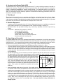
• The three tripod lock knobs (43) have been removed from the bottom section of each tripod leg to insure
safe arrival of the tripod assembly. To install, thread in each tripod lock knob into the threaded hole
located at the right side of each of the three gray colored castings (see illustration below) at the bottom
of each tripod leg. Tighten the tripod lock knob only to a “firm feel” to avoid damage to the tripod caused
by overtightening.
• Spread the tripod legs (1) to full extension so that the leg braces (42) are taut (should one of the tripod
leg braces slip out of the center triangle fastener, merely reposition the brace and slide it back into
position). Adjust the tripod with the attached equatorial mount (2) to
Threaded Hole
the desired height by loosening the tripod lock knobs and extend
the sliding inner section of each tripod leg; then tighten each knob.
• Remove the mounting knob (41) from the round accessory shelf
(40). Place the accessory shelf on top of the center triangle leg
brace fastener of the tripod (1) so that the threaded stud protruding
from the bottom of the shelf (40) passes through the hole in the
Leg Lock Knob
center. Then replace and tighten the accessory shelf mounting
Sliding Inner Leg
knob (41).
•
Attach the flexible cable controls (3) and (4). These cable controls
are secured in place with a firm tightening of the thumbscrew located at the end of each cable.
•
Holding the counterweight (5) firmly in one hand, slip the counterweight onto the counterweight shaft (6).
Attach the counterweight (5) and counterweight shaft (6), by supporting the unlocked (7) counterweight
firmly in one hand, while threading the counterweight shaft into the base of the Declination axis of the
telescope’s equatorial mount with the other (see Fig. 1). Once firmly attached, slide the counterweight
to the midpoint on the counterweight shaft and secure it in place with the lock knob (7) of the counterweight. Note: If the counterweight ever slips, the secured threaded safety washer/knob (8) will not let
the weight slide entirely off the counterweight shaft. Be certain that this safety washer/knob is
always in place.
–7–
•
Release the latitude lock (9) of the equatorial mount, and tilt the polar axis (10) of the telescope to
roughly a 45° angle by turning the latitude adjustment knob (11). With the polar axis thus tilted, firmly
re-tighten the latitude lock.
•
Loosen the lock knobs (15) of the cradle rings (14) and open the cradle rings to position them over the
optical tube assembly (12). Turn the lock knobs a few turns to keep the cradle rings closed, but to still
allow the cradle rings to slide freely up-and-down the main tube.
•
Remove the viewfinder bracket mounting nuts from the viewfinder bracket mounting bolts (16) that
protrude from the optical tube (12), near the focuser. Place the viewfinder bracket’s mounting holes
(located at the base of the bracket) over the mounting bolts, so that the bracket is oriented as shown in
Fig. 1. Replace the viewfinder bracket mounting nuts, and tighten to a firm feel. Then center the
viewfinder in both bracket rings by backing off the three thumbscrews (26) on each bracket ring. Orient
the viewfinder so its front objective lens is pointing in the same direction as the open end (front) of the
optical tube (25).
•
While firmly holding the optical tube (12), position it onto the optical tube saddle plate (13), with the midpoint of the optical tube’s length lying roughly in the center of the saddle plate. Then slide the cradle
rings (14) over the saddle plate of the mount. Tighten the cradle ring attachment knobs (37) to a firm
feel when the cradle rings are positioned over the telescope’s saddle (13). Then tighten the cradle ring
lock knobs (15) to a firm feel; do not overtighten these knobs. Please note that you may want to change
the rotational position of the optical tube to gain a more comfortable observing position of the focuser
(17). This adjustment may be performed several times in one observing session, as desired.
•
Insert the MA25mm eyepiece (19) into the focuser, and tighten the focuser thumbscrew (18) to secure
the eyepiece.
The telescope is now fully assembled. Before it can be properly used, however, the telescope must be
balanced and the viewfinder aligned.
1. Balancing the Telescope
In order for the telescope to move smoothly on its mechanical axes, it must first be balanced about the 2
telescope axes: the polar axis (10) and the Declination axis (21). All motions of the polar aligned telescope
(more on this later) take place by moving about these two axes, separately or simultaneously. To obtain a
fine balance of the telescope, follow the method below:
•
Loosen the R.A. lock (22) and rotate the telescope so that the counterweight shaft (6) is parallel to the
ground (horizontal).
•
Slide the counterweight along the counterweight shaft until the telescope remains in one position without
tending to drift down in either direction. Then tighten the counterweight lock knob (7), locking the
counterweight in position.
•
Lock the R.A. lock (22), and unlock the Declination lock (23). The telescope will now turn freely about
the Declination axis. Loosen the cradle ring lock knobs (15) so that the main tube in the cradle rings
slides easily up-or-down in the cradle rings. Move the main tube in the cradle rings until it is balanced
rotationally about the Declination axis. Re-lock the knobs (15).
The telescope is now properly balanced on both axes.
2. Alignment of the Viewfinder
The wide field of view provided by the 6 x 30mm viewfinder permits easy object sighting prior to observation
in the higher-power main telescope. The 6 x 30 Viewfinder (24) and viewfinder bracket (20) should be
attached to the telescope tube assembly as described above (see Figure 1). In order for the viewfinder to
be functional, however, it must be aligned to the main telescope, so that both the viewfinder and main
telescope point at the same position in the sky. With this simple alignment performed, finding objects is
greatly facilitated, since you will first locate an object in the wide-field viewfinder, then you will look in the
eyepiece of the main telescope for a detailed view. To align the viewfinder follow these steps:
•
Remove the telescope front dust cover (25), and the dust covers of the viewfinder.
•
Place the low- power (MA25mm) eyepiece into the focuser of the main telescope.
•
Unlock the R.A. lock (22) and the Dec. lock (23) so that the telescope turns freely on both axes. Then
point the main telescope at some well-defined land object (e.g. the top of a telephone pole) at least 200
yards distant, and re-lock the R.A and Dec. axes. Turn the flexible cable controls, (3) and (4), to center
the object in the telescopic field.
–8–
•
With the front of the viewfinder already centered in the front bracket ring, look through the viewfinder
and loosen or tighten, as appropriate, one or more of the rear viewfinder bracket ring thumbscrews (26)
until the viewfinder’s crosshairs are likewise centered on the object previously centered in the main
telescope.
•
Check this alignment on a celestial object, such as a bright star or the Moon, and make any refinements
necessary, using the method outlined above.
With this alignment performed, objects first located in the wide-field viewfinder will also be centered in the
main telescope’s field of view. (Note: The viewfinder and telescope present an image which is upside-down.)
C. Understanding Celestial Movements and Coordinates
Understanding where to locate celestial objects, and how those objects move across the sky is fundamental
to enjoying the hobby of astronomy. Most amateur astronomers adopt the simple practice of “star-hopping”
to locate celestial objects by using star charts or astronomical software which identify bright stars and star
patterns (constellations) that serve as “road maps” and “landmarks” in the sky. These visual reference
points guide amateur astronomers in their search for astronomical objects. And, while star-hopping is the
preferred technique, a discussion of using setting circles for locating objects is desirable since your
telescope is provided with this feature. However, be advised, compared to star-hopping, object location by
use of setting circles requires a greater investment in time and patience to achieve a more precise alignment
of the telescope’s polar axis to the celestial pole. For this reason, in part, star-hopping is popular because
it is the faster, easier way to become initiated in the hobby.
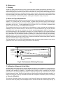
Understanding how astronomical objects move: Due to the Earth’s rotation, celestial bodies appear to
move from East to West in a curved path through the skies. The path they follow is known as their line of
Right Ascension (R.A.). The angle of this path they follow is known as their line of Declination (Dec.). Right
Ascension and Declination is analogous to the Earth-based coordinate system of latitude and longitude.
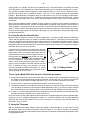
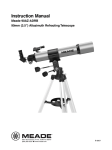
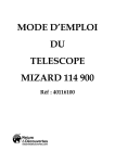
Understanding celestial coordinates: Celestial objects are mapped according to the R.A. and Dec.
coordinate system on the “celestial sphere” (Fig. 2), the imaginary sphere on which all stars appear to be
placed. The Poles of the celestial coordinate system are defined as those 2 points where the Earth's
rotational axis, if extended to infinity, North and South, intersect the celestial sphere. Thus, the North
Celestial Pole is that point in the sky where an extension of the Earth's axis through the North Pole intersects
the celestial sphere. In fact, this point in the sky is located near the North Star, or Polaris.
On the surface of the Earth, “lines of longitude” are drawn between the North and South Poles. Similarly,
“lines of latitude” are drawn in an East-West direction, parallel to the Earth's equator. The celestial equator
is simply a projection of the Earth's equator onto the celestial sphere. Just as on the surface of the Earth,
imaginary lines have been drawn on the celestial sphere to form a coordinate grid. Celestial object positions
on the Earth's surface are specified by their latitude and longitude.
The celestial equivalent to Earth latitude is called “Declination,” or simply “Dec,” and is measured in degrees,
minutes or seconds north ("+") or south ("-") of the celestial equator. Thus any point on the celestial equator
+90° Dec.
North Celestial Pole
(Vicinity of Polaris)
Star
17
18
19
15
14
13
12
11
tion
clina
De
16
10
8
7
6
5
Earth’s Rotation
20
4
21
22
23
0
1
2
Right Ascension
South Celestial Pole
9
-90° Dec.
Fig. 2: Celestial Sphere
3
0° Dec.
Celestial Equator
–9–
(which passes, for example, through the constellations Orion, Virgo and Aquarius) is specified as having
0°0'0" Declination. The Declination of the star Polaris, located very near the North Celestial Pole, is +89.2°.
The celestial equivalent to Earth longitude is called “Right Ascension,” or “R.A.” and is measured in hours,
minutes and seconds from an arbitrarily defined “zero” line of R.A. passing through the constellation
Pegasus. Right Ascension coordinates range from 0hr0min0sec up to (but not including) 24hr0min0sec.
Thus there are 24 primary lines of R.A., located at 15 degree intervals along the celestial equator. Objects
located further and further east of the prime (0h0m0s) Right Ascension grid line carry increasing R.A.
coordinates.
With all celestial objects therefore capable of being specified in position by their celestial coordinates of
Right Ascension and Declination, the task of finding objects (in particular, faint objects) in the telescope is
vastly simplified. The setting circles, R.A (27) and Dec. (28) of the Model 4500 telescope may be dialed, in
effect, to read the object coordinates and the object found without resorting to visual location techniques.
However, these setting circles may be used to advantage only if the telescope is first properly aligned with
the North Celestial Pole.
D. Lining Up with the Celestial Pole
Objects in the sky appear to revolve around the celestial pole. (Actually, celestial objects are essentially
“fixed,” and their apparent motion is caused by the Earth’s axial rotation). During any 24 hour period, stars
make one complete revolution about the pole, making concentric circles with the pole at the center. By lining
up the telescope’s polar axis with the North Celestial Pole (or for observers located in Earth’s Southern
Hemisphere with the South Celestial Pole), astronomical objects may be followed, or tracked, by moving the
telescope about one axis, the polar axis.
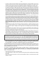
If the telescope is reasonably well aligned with the pole,
therefore, very little use of the telescope’s Declination
flexible cable control is necessary and virtually all of the
required telescope tracking will be in Right Ascension. (If
the telescope were perfectly aligned with the pole, no
Declination tracking of stellar objects would be required).
For the purposes of casual visual telescopic observations, lining up the telescope’s polar axis to within a
degree or two of the pole is more than sufficient: with this
level of pointing accuracy, the telescope can track
accurately by slowly turning the telescope’s R.A. flexible
cable control and keep objects in the telescopic field of
view for perhaps 20 to 30 minutes.
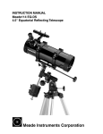
Little Dipper
Big Dipper
Polaris
Cassiopeia
Fig. 3: Finding Polaris
To line up the Model 4500 with the pole, follow this procedure:
1) Release the Azimuth lock (30) of the Azimuth base (33), so that the entire telescope-with-mounting may
be rotated in a horizontal direction. Rotate the telescope until the polar axis (10) points due North. Use
a compass or locate Polaris, the North Star (see Fig. 3), as an accurate reference for due North.
2) Level the mount, if necessary, by adjusting the heights of the three tripod legs.
3) Determine the latitude of your observing location by checking a road map or atlas. Release the latitude
lock (9) and tilt the telescope mount with the latitude adjustment knob (11) so that the pointer indicates
the correct latitude of your viewing location on the latitude scale (29). Re-tighten the latitude lock (9).
4) If steps (1) - (3) above were performed with reasonable accuracy, your telescope is now sufficiently wellaligned to the North Celestial Pole for visual observations.
Once the mount has been polar-aligned as described above, the latitude angle need not be adjusted again,
unless you move to a different geographical location (i.e. a different latitude). The only polar alignment
procedure that need be done each time you use the telescope is to point the polar axis due North, as
described in step (1) above.
E. Using the Telescope
With the telescope assembled, balanced and polar aligned as described above, you are ready to begin
observations. Decide on an easy-to-find object such as the Moon, if it is visible, or a bright star to become
accustomed to the functions and operations of the telescope. For the best results during observations, follow
the suggestions below:
– 10 –
•
To center an object in the main telescope, loosen the telescope’s R.A. lock (22) and Dec. lock (23). The
telescope can now turn freely on its axes. Use the aligned viewfinder to first sight-in on the object you wish
to observe; with the object centered on the viewfinder’s crosshairs, re-tighten the R.A. and Dec. locks.
•
If you have purchased an assortment of eyepieces (see Section G on Calculating Power and Section J
on Optional Accessories for higher and lower powers with the telescope), always start an observation
with a low power eyepiece (e.g. the MA25mm eyepiece); get the object well-centered in the field of view
and sharply focused. Then try the next step up in magnification. If the image starts to become fuzzy
as you work into higher magnifications, then back down to a lower power; the atmospheric steadiness
is not sufficient to support high powers at the time you are observing. Keep in mind that a bright, clearly
resolved but smaller image will show far more detail than a dimmer, poorly resolved larger image. The
MA25mm eyepiece included with the Model 4500 presents a wide field of view, ideal for general
astronomical observing of star fields, clusters of stars, nebulae, and galaxies; it is also probably the best
eyepiece to use in the initial finding and centering of any object.
•
Once centered, the object can be focused by turning one of the knobs of the focusing mechanism (31).
You will notice that the astronomical object in the field of view will begin to slowly move across the
eyepiece field. This motion is caused by the rotation of the Earth on its axis, as described in Section C,
although the planets and stars, are, for practical purposes, fixed in their positions in the sky. The platform
on which the telescope is sitting ( the Earth) rotates once every 24 hours under these objects.To keep
astronomical objects centered in the field of the polar aligned telescope, simply turn the R.A.
flexible cable control (3).These objects will appear to move through the field more rapidly at higher
powers. Note that the Declination flexible cable control is used only for centering purposes, and not for
tracking.
Avoid touching the eyepiece while observing through the telescope. Vibrations resulting from such
contact will cause the image to move. Likewise, avoid observing sites where ground-based vibrations
may resonate the tripod. Viewing from the upper floors of a building may also introduce image
movement.
•
•
You should allow a few minutes to allow your eyes to become “dark adapted” before attempting any
serious astronomical observations. Use a red filtered flashlight to protect your night vision when reading
star maps or inspecting the components of the telescope.
•
Avoid setting up the telescope inside a room and observing through an open window (or worse yet, a
closed window). Images viewed in such a manner may appear blurred or distorted due to temperature
differences between inside and outside air. Also, it is a good idea to allow your telescope a chance to
reach the ambient (surrounding) outside temperature before starting an observing session.
We repeat the warning stated at the outset of this manual: Never point the telescope directly at or
near the Sun at any time! Observing the Sun, even for the smallest fraction of a second, will
result in instant and irreversible eye damage, as well as physical damage to the telescope itself.
•
Avoid viewing objects low on the horizon–objects will appear better resolved with far greater contrast
when viewed higher in the sky. Also, if images appear to “shimmer” in the eyepiece–reduce power until
the image steadies. This condition is caused by air turbulence in the upper atmosphere.
The Meade Model 4500 may be used for a lifetime of rewarding astronomical observing, but basic to your
enjoyment of the telescope is a good understanding of the instrument. Read the above instructions carefully
until you understand all of the telescope’s parts and functions. One or two observing sessions will serve to
clarify these points forever in your mind.
The number of fascinating objects visible through your Meade reflector is limited only by your own
motivation. Astronomical software, such as Meade’s AstroSearch, or a good star atlas, such as Meade Star
Charts (see OPTIONAL ACCESSORIES, page 15) will assist you in locating many interesting celestial
objects. These objects include:
•
Cloud belts across the surface of the planet Jupiter.
•
The 4 major satellites of Jupiter, visible in rotation about the planet, with the satellite positions changing
each night.
•
Saturn and its famous ring system, as well as several satellites of Saturn, much fainter than the major
satellites of Jupiter.
– 11 –
•
The Moon: A veritable treasury of craters, mountain ranges and fault lines. The best contrast for viewing
the Moon is during its crescent phase. The contrast during the full Moon phase is low due to the angle
of illumination.
•
Deep-Space: Nebulae, galaxies, multiple star systems, star clusters–hundreds of such objects are
visible through the Model 4500.
F. Using Setting Circles
Setting circles of the polar aligned equatorial mount can facilitate the location of faint celestial objects not
easily found by direct visual observation. To use the setting circles, follow this procedure:
•
Use a star chart or star atlas, and look up the celestial coordinates, Right Ascension and Declination
(R.A. and Dec.), of an easy-to-find bright star that is within the general vicinity of the faint object you
wish to locate.
•
Center the determined bright star in the telescope’s field of view.
•
Manually turn the R.A. setting circle (27) to read the R.A. of the object now in the telescope’s eyepiece.
•
The setting circles are now calibrated (the Dec. setting circle (28) is factory calibrated). To locate a
nearby faint object using the setting circles determine the faint object’s celestial coordinates from a star
chart, and move the telescope in R.A. and Declination until the setting circles read the R.A. and Dec. of
the object you are attempting to locate. If the above procedure has been carefully performed, the faint
object will now be in the field of a low power eyepiece.
The R.A. Setting Circle must be manually re-calibrated on the current Right Ascension of a star every
time the telescope is set up, and reset to the centered object’s R.A. coordinate before moving to a new
R.A. coordinate setting. The R.A. Setting Circle has two sets of numbers, the inner set is for Southern
hemisphere use while the outer set of numbers (the set closest to the R.A. gear), is for use by observers
located North of the Earth’s equator (e.g. in North America).
•
G. Calculating Power
The power, or magnification of the telescope depends on two optical characteristics: the focal length of the
main telescope and the focal length of the eyepiece used during a particular observation. For example, the
focal length of the Model 4500 telescope is fixed at 910mm. To calculate the power in use with a particular
eyepiece, divide the focal length of the eyepiece into the focal length of the main telescope. For example,
using the MA25mm eyepiece supplied with the Model 4500, the power is calculated as follows:
910mm
Power = 25mm = 36x
Meade Instruments manufactures several types of eyepiece designs that are available for your telescope.
The type of eyepiece (“MA” Modified Achromatic, “SP” Super Plössl, etc.) has no bearing on magnifying
power but does affect such optical characteristics as field of view, flatness of field, eye-relief, and color
correction.
The maximum practical magnification is determined by the nature of the object being observed and, most
importantly, by the prevailing atmospheric conditions. Under very steady atmospheric “seeing,” the Model
4500 may be used at powers up to about 228x on astronomical objects. Generally, however, lower powers
of perhaps 75x to 175x will be the maximum permissible, consistent with high image resolution. When
unsteady air conditions prevail (as witnessed by rapid “twinkling” of the stars), extremely high-power
eyepieces result in “empty magnification,” where the object detail observed is actually diminished by the
excessive power.
Assorted eyepieces are available both to increase and decrease the operating eyepiece power of the
telescope. If the Model 4500 is used on a regular basis, a selection of four to five eyepieces is recommended. For example, an eyepiece assortment of focal lengths 40mm, 25mm*, 12.5mm, 9mm, and 6mm
yields a magnifying range of 22.5x, 36x, 72x, 101x, and 150x respectively. A high quality Barlow Lens, such
as the Meade #126 2x Telenegative Barlow Lens, serves to double the power of each of these eyepieces.
To use the Barlow Lens, insert the #126 unit into the telescope’s focuser first, followed by an eyepiece; the
power thus obtained is then double the power obtained when the eyepiece is used alone. For example, the
MA25mm eyepiece, when used in conjunction with the #126 2x Telenegative Barlow Lens yields 72x.
– 12 –
H. Maintenance
1. Cleaning
As with any quality instrument, lens or mirror surfaces should be cleaned as infrequently as possible. Front
surface aluminized mirrors, in particular, should be cleaned only when absolutely necessary. In all cases
avoid touching any mirror surface. A little dust on the surface of a mirror or lens causes negligible loss of
performance and should not be considered reason to clean the surface. When lens or mirror cleaning does
become necessary, use a camel’s hair brush or compressed air gently to remove dust. If the telescope’s dust
cover is replaced after each observing session, cleaning of the optics will rarely be required.
2. Mount and Tripod Adjustments
Every Meade Model 4500 equatorial mount and tripod is factory inspected for proper fit and function prior to
shipment. It is unlikely that you will need to adjust, or tighten these parts after receipt of the telescope.
However, if the instrument received unusually rough handling in shipment, it is possible that some of these
assemblies can be loose. To make adjustments you will need a 1/2" or 11/16" socket or adjustable end
wrench, a 5/64" hex wrench, and a Phillips-head screwdriver.
The equatorial mount has four main areas that can be adjusted: A loose polar shaft can be tightened by
releasing a 5/64" hex set-screw that is on the side of the 11/16" polar shaft acorn cap nut (32), and then
turning the 11/16" acorn cap nut clockwise to a firm feel, and then tightening the 5/64" hex set-screw. A
loose Azimuth base (33), can be tightened by turning the 11/16" Azimuth shaft bolt (34), located underneath
the mount and in between the three tripod legs, clockwise to a firm feel. The R.A. (35), and Dec. (36) worm
block assemblies can have backlash removed by releasing the 2 Phillips-head screws on each assembly,
applying pressure to the worm block against the worm gear, and then tightening the Phillips-head screws.
Note that overtightening of any of the nuts, bolts, or screws can inhibit the smooth rotating action of the axes
and gears, and may result in stripping the threads.
The tripod legs have 1/2" nuts (39), and Phillips-head screws (38) that may have backed off, may also be
tightened to a firm feel for the most sturdy performance of the telescope.
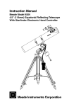
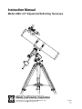
Diagonal
Assembly
Diagonal Mirror
Focused Image
Primary Mirror
Primary Mirror-Tilt
Screws
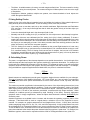
Fig. 4: The Newtonian Reflecting Telescope
3. Collimation (Alignment) of the Optics
All Meade Model 4500 telescopes are optically aligned at the factory prior to shipment. It is unlikely that you
will need to align, or collimate, the optics after receipt of the instrument. However, if the telescope received
unusually rough handling in shipment, it is possible that the optics must be re-aligned for best optical
performance. In any case this alignment procedure is simple, and requires only a few minutes the very first
time the telescope is used. Take the time to familiarize yourself with the following collimation procedure, so
that you will recognize a properly collimated instrument and can adjust the collimation yourself, if necessary.
a. Correct collimation
The properly collimated (aligned) mirror system in the Model 4500 assures the sharpest images possible.
This occurs when the primary mirror and diagonal mirror are tilted so that the focused image (see Fig. 4)
– 13 –
2
3
1
2
3
Fig. 5: Diagonal Assembly
Fig. 6: Primary Mirror Cell
falls directly through the center of the focuser drawtube (17, Fig. 1). These mirror tilt adjustments are made
with the diagonal assembly (Fig. 5) and the primary mirror cell (Fig. 6), and will be discussed later.
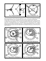
To inspect the view of the mirror collimation, look down the focuser drawtube with the eyepiece removed.
The edge of the focuser drawtube (1, Fig. 7), will frame the reflections of the primary mirror with the 3 mirror
clips (2, Fig. 7), the diagonal mirror (3, Fig. 7) , the spider vanes (4, Fig. 7), and your eye (5, Fig. 7). Properly
aligned, all of these reflections will appear concentric (i.e. centered) as illustrated in Figure 7. Any deviation
from the concentric reflections will require adjustments to the diagonal assembly (Fig. 5), and/or the primary
mirror cell (Fig. 6).
1
2
2
2
3
4
1
5
Fig. 7: Correct Collimation
Fig. 8: Spider Vane Misalignment
1
1
3
2
4
3
2
Fig. 9: Diagonal Mirror Misalignment
Fig. 10: Primary Mirror Misalignment
– 14 –
b. Spider vane adjustments
If the diagonal mirror (1, Fig. 8) is left or right of center within the drawtube (2, Fig. 8), loosen the spider vane
adjustment/lock knobs (1, Fig. 5) located on the outside surface of the main tube and slide the entire
diagonal assembly up or down the tube along the slotted holes, until the diagonal mirror is centered in the
drawtube.
If the diagonal mirror (1, Fig. 8) is above or below of center within the drawtube, thread in one of the spider
vane adjustment/ lock knobs while unthreading the other. Only make adjustments to 2 knobs at a time until
the diagonal mirror is in the drawtube. When the spider vane is correctly positioned, it will look like Fig. 9.
(Note that the diagonal mirror is misaligned.)
c. Diagonal holder adjustments
If the diagonal mirror (1, Fig. 9) is centered in the drawtube (2, Fig. 9), but the primary mirror is only partially
visible in the reflection (3, Fig. 9), the 3 Phillips-head diagonal tilt screws (2, Fig. 5) must be unthreaded
slightly to the point of where you can rotate the diagonal holder (3, Fig. 5) from side-to-side by grasping the
diagonal holder with your hand and rotating until you see the primary mirror become as centered in the
reflection of the diagonal mirror as possible. Once you are at the best position, thread in the 3 Phillips-head
diagonal tilt screws to lock the rotational position. Then, if necessary, make adjustments to these 3 Phillipshead screws to refine the tilt-angle of the diagonal mirror until the entire primary mirror can be seen centered
within the diagonal mirror reflection. When the diagonal mirror is correctly aligned, it will look like Fig. 10.
(Note that the primary mirror is shown out of alignment.)
Fig. 11A
Fig. 11B
Fig. 11C
d. Primary mirror adjustments
If the diagonal mirror (1, Fig. 10) and the reflection of the primary mirror (2, Fig. 10) appear centered within
the drawtube (3, Fig. 10), but the reflection of your eye and the reflection of the diagonal mirror (4, Fig. 10)
appear off-center, you will need to adjust the primary mirror tilt Phillips-head screws of the primary mirror cell
(3, Fig. 6). These primary tilt screws are located behind the primary mirror, at the lower end of the main
tube. See Fig. 4. To adjust the primary mirror tilt screws, first unscrew several turns, the 3 hex-head primary
mirror cell locking screws (2, Fig.6) that are next to each primary mirror tilt Phillips-head screw. Then by trialand-error, turn the primary mirror tilt Phillips-head screws (3, Fig. 6) until you develop a feel for which way
to turn each screw to center the reflection of your eye. Once centered, as in Fig. 7, turn the 3 hex-head
primary mirror cell locking screws (2, Fig. 6) to relock the tilt-angle adjustment.
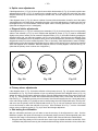
e. Star testing the collimation
With the collimation performed, you will want to test the accuracy of the alignment on a star. Use the
MA25mm eyepiece and point the telescope at a moderately bright (second or third magnitude) star, then
center the star image in the telescope’s field-of-view. With the star centered follow the method below:
•
Bring the star image slowly out of focus until one or more rings are visible around the central disc. If the
collimation was performed correctly, the central star disk and rings will be concentric circles, with a dark
– 15 –
spot dead center within the out-of-focus star disk (this is the shadow of the secondary mirror), as shown
in Fig.11C. (An improperly aligned telescope will reveal elongated circles (Fig. 11A), with an off-center
dark shadow.)
•
If the out-of-focus star disk appears elongated (Fig. 11A), you will need to adjust the primary mirror
Phillips-head tilt screws of the primary mirror cell (3, Fig. 6).
•
To adjust the primary mirror tilt screws (3, Fig. 6), first unscrew several turns the 3 hex-head primary
mirror cell locking screws (2, Fig. 6), to allow free turning movement of the tilt knobs.
•
Using the flexible cable controls (3) and (4), Fig. 1, move the telescope until the star image is at the edge
of the field-of-view in the eyepiece, as in Fig. 11B.
•
As you make adjustments to the primary mirror tilt screws (3, Fig. 6), you will notice that the out-of-focus
star disk image will move across the eyepiece field. Choose one of the 3 primary mirror tilt screws that
will move the star disk image to the center of the eyepiece field.
•
Repeat this process as many times as necessary until the out-of-focus star disk appears as in Fig. 11C,
when the star disk image is in the center of the eyepiece field.
•
With the star testing of the collimation complete, tighten the 3 hex-head primary mirror locking screws
(2, Fig. 6).
I. Specifications: Model 4500
Primary (main) mirror focal length:
Primary mirror diameter: . . . . . . . .
Focal ratio: . . . . . . . . . . . . . . . . . .
Mounting: . . . . . . . . . . . . . . . . . . .
.
.
.
.
.
.
.
.
.
.
.
.
.
.
.
.
.
.
.
.
.910mm
.4.5" (114mm)
.f/8
.German equatorial
J. Optional Accessories
Refer to the latest Meade General Catalog.
American-Size Eyepieces (1.25" O.D.): Meade Instruments offers several types of high-performance,
American-sized eyepiece to fit every observing requirement and budget. See the Meade General Catalog,
Meade advertising in Sky & Telescope and Astronomy magazines, or contact your full-service Meade dealer
for details and suggestions on purchasing optional Meade accessory eyepieces.
#126 2x Telenegative Barlow Lens (1.25" O.D.): The high-quality #126 Barlow lens serves to double the
power of any American-size (1.25") eyepiece used.
#531 Electric Motor Drive: With the #531 Motor Drive attached, the telescope automatically tracks
astronomical objects in their paths across the sky. Three AA size (user-supplied) batteries power the DC
servo motor to rotate the Right Ascension control shaft of the telescope at a constant rate that results in one
revolution of the telescope in RA every 24 hours, fully compensating for the effects of the Earth’s rotation.
The #531 Motor Drive easily attaches in minutes to the telescope. A North-South switch permits operation
in either of the Earth’s northern or southern hemispheres.
AstroSearch Sky Software: 3.5" disks for Windows 3.1 or higher. Explore the heavens with AstroSearch
and your personal computer—visually displays the night sky and allows the printing of detailed star charts.
Provides locations of planets, galaxies, star clusters, nebulae—over 45,000 objects as well as a lunar
calendar.
FOR PHOTOGRAPHY
To allow use of the Model 4500 for photography, the following accessories must be purchased:
#126 2x Telenegative Barlow Lens (1.25” O.D.): To permit photography, the #126 Barlow lens must be
placed into the focuser’s Eyepiece Holder Adapter (1.25"), then the Variable Projection Camera Adapter
must be attached to the #126 Barlow lens via the thumbscrew lock provided for that purpose.
Variable Projection Camera Adapter (1.25" O.D.): The Variable Projection Camera Adapter includes a
machined sliding mechanism, permitting variable projection distances during eyepiece-projection
photography. The Variable Projection Camera Adapter (1.25") permits direct attachment of 35mm SLR
cameras to the Model 4500’s focuser for short exposure astrophotography of the Moon. (Requires T-Mount
for your specific brand of 35mm camera and an appropriate focal length eyepiece. Also, the Variable
Projection Camera Adapter must be used with the #126 Barlow Lens, mentioned above.
ADVANCED
PRODUCTS
DIVISION
Meade Instruments Corporation
World’s Leading Manufacturer of Astronomical Telescopes for the Serious Amateur
6001 Oak Canyon, Irvine, California 92618 ■ (949) 451-1450
FAX: (949) 451-1460 ■ www.meade.com